EP3218299B2 - Appareil de préparation de boissons - Google Patents
Appareil de préparation de boissons Download PDFInfo
- Publication number
- EP3218299B2 EP3218299B2 EP14796764.0A EP14796764A EP3218299B2 EP 3218299 B2 EP3218299 B2 EP 3218299B2 EP 14796764 A EP14796764 A EP 14796764A EP 3218299 B2 EP3218299 B2 EP 3218299B2
- Authority
- EP
- European Patent Office
- Prior art keywords
- housing
- valve
- preparation apparatus
- liquid
- drink
- Prior art date
- Legal status (The legal status is an assumption and is not a legal conclusion. Google has not performed a legal analysis and makes no representation as to the accuracy of the status listed.)
- Active
Links
- 238000002360 preparation method Methods 0.000 title claims description 85
- 235000013361 beverage Nutrition 0.000 title description 101
- 239000007788 liquid Substances 0.000 claims description 139
- CURLTUGMZLYLDI-UHFFFAOYSA-N Carbon dioxide Chemical compound O=C=O CURLTUGMZLYLDI-UHFFFAOYSA-N 0.000 claims description 104
- XLYOFNOQVPJJNP-UHFFFAOYSA-N water Substances O XLYOFNOQVPJJNP-UHFFFAOYSA-N 0.000 claims description 78
- 229910002092 carbon dioxide Inorganic materials 0.000 claims description 52
- 239000001569 carbon dioxide Substances 0.000 claims description 52
- 230000001105 regulatory effect Effects 0.000 claims description 42
- 239000003651 drinking water Substances 0.000 claims description 16
- 235000020188 drinking water Nutrition 0.000 claims description 16
- 238000002156 mixing Methods 0.000 claims description 14
- 230000001276 controlling effect Effects 0.000 claims description 8
- 230000001678 irradiating effect Effects 0.000 claims description 3
- 230000005855 radiation Effects 0.000 claims description 3
- 238000001914 filtration Methods 0.000 claims description 2
- 230000000249 desinfective effect Effects 0.000 claims 4
- 238000010079 rubber tapping Methods 0.000 claims 1
- 238000004659 sterilization and disinfection Methods 0.000 description 10
- 230000001954 sterilising effect Effects 0.000 description 9
- 238000012423 maintenance Methods 0.000 description 7
- 230000002349 favourable effect Effects 0.000 description 5
- 230000008439 repair process Effects 0.000 description 5
- 239000012530 fluid Substances 0.000 description 4
- 239000003638 chemical reducing agent Substances 0.000 description 3
- 238000004140 cleaning Methods 0.000 description 3
- 239000011521 glass Substances 0.000 description 3
- 239000000126 substance Substances 0.000 description 3
- 238000001816 cooling Methods 0.000 description 2
- 238000011161 development Methods 0.000 description 2
- 235000014676 Phragmites communis Nutrition 0.000 description 1
- 244000052616 bacterial pathogen Species 0.000 description 1
- 235000014171 carbonated beverage Nutrition 0.000 description 1
- 238000003763 carbonization Methods 0.000 description 1
- 238000004891 communication Methods 0.000 description 1
- 230000000694 effects Effects 0.000 description 1
- 238000011049 filling Methods 0.000 description 1
- 230000002070 germicidal effect Effects 0.000 description 1
- 230000005484 gravity Effects 0.000 description 1
- 238000010438 heat treatment Methods 0.000 description 1
- 239000008236 heating water Substances 0.000 description 1
- 239000012535 impurity Substances 0.000 description 1
- 238000001746 injection moulding Methods 0.000 description 1
- 238000007726 management method Methods 0.000 description 1
- 239000000463 material Substances 0.000 description 1
- 238000005259 measurement Methods 0.000 description 1
- 239000002184 metal Substances 0.000 description 1
- 238000000034 method Methods 0.000 description 1
- 239000000203 mixture Substances 0.000 description 1
- NJPPVKZQTLUDBO-UHFFFAOYSA-N novaluron Chemical compound C1=C(Cl)C(OC(F)(F)C(OC(F)(F)F)F)=CC=C1NC(=O)NC(=O)C1=C(F)C=CC=C1F NJPPVKZQTLUDBO-UHFFFAOYSA-N 0.000 description 1
- 230000000149 penetrating effect Effects 0.000 description 1
- 230000035515 penetration Effects 0.000 description 1
- 230000002787 reinforcement Effects 0.000 description 1
- 238000009420 retrofitting Methods 0.000 description 1
- 239000000243 solution Substances 0.000 description 1
- 238000012360 testing method Methods 0.000 description 1
- 238000009736 wetting Methods 0.000 description 1
Images


Classifications
-
- B—PERFORMING OPERATIONS; TRANSPORTING
- B67—OPENING, CLOSING OR CLEANING BOTTLES, JARS OR SIMILAR CONTAINERS; LIQUID HANDLING
- B67D—DISPENSING, DELIVERING OR TRANSFERRING LIQUIDS, NOT OTHERWISE PROVIDED FOR
- B67D1/00—Apparatus or devices for dispensing beverages on draught
- B67D1/06—Mountings or arrangements of dispensing apparatus in or on shop or bar counters
-
- B—PERFORMING OPERATIONS; TRANSPORTING
- B67—OPENING, CLOSING OR CLEANING BOTTLES, JARS OR SIMILAR CONTAINERS; LIQUID HANDLING
- B67D—DISPENSING, DELIVERING OR TRANSFERRING LIQUIDS, NOT OTHERWISE PROVIDED FOR
- B67D1/00—Apparatus or devices for dispensing beverages on draught
- B67D1/08—Details
-
- B—PERFORMING OPERATIONS; TRANSPORTING
- B67—OPENING, CLOSING OR CLEANING BOTTLES, JARS OR SIMILAR CONTAINERS; LIQUID HANDLING
- B67D—DISPENSING, DELIVERING OR TRANSFERRING LIQUIDS, NOT OTHERWISE PROVIDED FOR
- B67D1/00—Apparatus or devices for dispensing beverages on draught
- B67D1/08—Details
- B67D1/12—Flow or pressure control devices or systems, e.g. valves, gas pressure control, level control in storage containers
- B67D1/1202—Flow control, e.g. for controlling total amount or mixture ratio of liquids to be dispensed
- B67D1/1234—Flow control, e.g. for controlling total amount or mixture ratio of liquids to be dispensed to determine the total amount
- B67D1/1243—Flow control, e.g. for controlling total amount or mixture ratio of liquids to be dispensed to determine the total amount comprising flow or pressure sensors, e.g. for controlling pumps
-
- B—PERFORMING OPERATIONS; TRANSPORTING
- B67—OPENING, CLOSING OR CLEANING BOTTLES, JARS OR SIMILAR CONTAINERS; LIQUID HANDLING
- B67D—DISPENSING, DELIVERING OR TRANSFERRING LIQUIDS, NOT OTHERWISE PROVIDED FOR
- B67D1/00—Apparatus or devices for dispensing beverages on draught
- B67D1/08—Details
- B67D1/16—Devices for collecting spilled beverages
-
- B—PERFORMING OPERATIONS; TRANSPORTING
- B67—OPENING, CLOSING OR CLEANING BOTTLES, JARS OR SIMILAR CONTAINERS; LIQUID HANDLING
- B67D—DISPENSING, DELIVERING OR TRANSFERRING LIQUIDS, NOT OTHERWISE PROVIDED FOR
- B67D2210/00—Indexing scheme relating to aspects and details of apparatus or devices for dispensing beverages on draught or for controlling flow of liquids under gravity from storage containers for dispensing purposes
- B67D2210/00028—Constructional details
- B67D2210/00031—Housing
- B67D2210/00034—Modules
-
- B—PERFORMING OPERATIONS; TRANSPORTING
- B67—OPENING, CLOSING OR CLEANING BOTTLES, JARS OR SIMILAR CONTAINERS; LIQUID HANDLING
- B67D—DISPENSING, DELIVERING OR TRANSFERRING LIQUIDS, NOT OTHERWISE PROVIDED FOR
- B67D2210/00—Indexing scheme relating to aspects and details of apparatus or devices for dispensing beverages on draught or for controlling flow of liquids under gravity from storage containers for dispensing purposes
- B67D2210/00028—Constructional details
- B67D2210/00031—Housing
- B67D2210/00041—Doors
Definitions
- the present invention relates to a beverage preparation device with at least one liquid inlet, a beverage dispensing device comprising at least one beverage outlet, a liquid line network fluidically connecting the at least one liquid inlet and the at least one beverage outlet, and a housing, the housing comprising an upper housing cover, with a valve carrier underneath the upper housing cover is arranged on which at least two control and/or regulating valves of the beverage preparation device are arranged and are freely accessible after removing the upper housing cover, and wherein a housing base is essentially trough-shaped and includes an integrally formed liquid collection container.
- Beverage preparation devices of the type described above are known, for example, in the form of so-called water dispensers, which are used in particular to dispense treated drinking water.
- Housings of such water dispensers are usually made of sheet metal and also have metallic frame parts.
- individual components for example solenoid valves for controlling a liquid flow through the liquid line network, are distributed in the housing essentially in any way and are connected to the liquid line network. This results in problems when carrying out regular maintenance and occasional repairs of the beverage preparation devices, which lead to time-consuming and therefore costly interventions, not least because individual components of the beverage preparation devices are difficult to access.
- a modular drinks dispenser is known.
- Another drinks dispenser is in the WO 02/12805 A1 described.
- the US 2012/0055954 A1 relates to a multiple distributor system for beverage dispensers WO 92/21607 A1 a convertible drinks dispenser is known.
- a convertible drinks dispenser is known in the GB 2 247 848 A.
- the US 2007/0266861 A1 relates to beverage dispensers having a drip tray assembly. From the WO 2013/087607 A2 a drip tray for a drinks dispenser is known.
- a housing base is essentially trough-shaped and includes an integrally designed liquid collection container.
- trough-shaped does not mean that an essentially complete area of the housing base has to form the trough. This can also only take up part of the area defined by the bottom of the housing.
- the liquid collection container can in particular serve the purpose of collecting liquid that has escaped in the event of leaks, so that it does not run out of the housing and, for example, impinge on a floor or a piece of furniture on which the beverage preparation device is set up with a liquid flowing through the liquid line network in an undesired manner and in particular can pollute.
- the housing base has a housing base surface set back from a housing base exterior pointing away from the housing cover in the direction of the housing cover and that the liquid collecting container at least partially surrounds the housing base surface.
- the liquid collection container can be designed in the form of a partially or completely encircling channel, which defines a volume in order to receive not only liquid in the event of a leak, but also, for example, condensed liquid that can condense inside the housing, for example, if the beverage preparation device is optional includes a cooling device.
- the cooling device can be used, for example, to cool a liquid or a beverage flowing through the beverage outlet, specifically before or during the flow through the beverage outlet. In particular, this can be advantageous in connection with a carbonator in order to efficiently add carbon dioxide to the liquid.
- the housing base designed in the manner described with the recessed housing base surface also makes it possible in particular to position components of the beverage preparation device in such a way that there is no risk that, in the event of liquid escaping from the liquid line network, this Components can be permanently flooded with liquid. They are therefore arranged higher than the liquid collection container and can therefore be arranged with optimal protection.
- the housing is designed in the form of a self-supporting housing, that the housing comprises a plurality of housing parts made of a plastic and that at least some of the housing parts have component holding devices for holding further components forming the beverage preparation device .
- the proposed development has the advantage that the weight of the beverage preparation device can be significantly reduced by designing the housing with housing parts made partially or entirely of plastic compared to beverage preparation devices available on the market.
- the component holding devices make it possible to easily mount further components of the beverage preparation device on at least some of the housing parts.
- line or cable holders can be provided on one or more housing parts in order to attach cables to them, for example by clipping them in place.
- they can also be receptacles into which, for example, valves, switches or electrically operated units of the beverage preparation device can be inserted and mounted with or without additional fastening elements.
- a separate frame of the housing can be dispensed with in particular if the housing is at least partially formed from self-supporting plastic components.
- the top cover and/or a side wall of the housing can not only have the function of closing the housing, but also of carrying or holding at least some of the components contained therein, which are arranged on the respective self-supporting plastic component.
- the housing parts preferably include in particular the valve carrier, the upper housing cover, a housing rear wall, a housing front wall, a right and a left housing side wall, an intermediate housing part arranged between the housing front wall and the housing rear wall, and a housing base.
- the intermediate housing part is not absolutely necessary.
- one or more of the housing parts mentioned can also be formed in one piece with one another.
- cable holding elements for fixing connecting lines and/or cables are arranged or formed on at least some of the housing parts.
- the cable holding elements can be formed integrally with one or more housing parts.
- this configuration facilitates the assembly of connecting lines and/or cables on the housing, since neither screws nor clamps or hooks or other elements are required to fix the connecting lines and/or cables to the housing.
- the cable holding elements are favorably designed in the form of lugs or hooks. This makes it possible, in particular, to feed connecting lines and/or cables, for example, through lugs or to hang them in hooks on one or more housing parts, so that they can be arranged easily and quickly during assembly. In addition, the clarity of the structure of the beverage preparation device can also be improved in this way.
- the at least two control and/or regulating valves are designed in the form of electrically controllable valves.
- the at least two control and/or regulating valves have a valve drive for opening and/or closing them.
- the valve drive can be in the form of an electromagnetic or pneumatic valve drive.
- a position of the control and/or regulating valves can be changed by an electrical or pneumatic control current, for example in order to permit or prevent a liquid flow through the liquid line network.
- the at least two control and/or regulating valves preferably have a valve inlet and a valve outlet, which point in opposite directions from one another. In particular, longitudinal axes of the valve inlet and the valve outlet can run parallel to one another or even coincide. With an arrangement of at least two control and/or regulation valves on the valve carrier, it is thus possible to arrange the control and/or regulation valves in such a way that both the valve inlet and the valve outlet are freely accessible after removing the upper housing cover.
- the at least two control and/or regulating valves are arranged on the valve carrier in such a way that their valve inlets and valve outlets point in the direction of a rear side of the housing or in the direction of a front side of the housing.
- all the control and/or regulating valves can be arranged in the manner described. This allows connecting lines of the liquid line network be connected to the at least two control and/or regulating valves in a clear manner and in the same orientation.
- the at least one control and/or regulating valve is arranged on the valve carrier in such a way that the valve drive is arranged between the valve inlet and the valve outlet on the one hand and the housing cover on the other.
- the valve drive can be arranged directly below the upper housing cover, ie is freely accessible when this is removed from the housing. The valve drive then sits above, ie facing the upper housing cover, the valve inlet and the valve outlet.
- the beverage preparation device comprises a pressure switch.
- at least one pressure switch which interacts with or is connected to the liquid line network and/or a CO 2 line network can be arranged on the valve carrier. Due to the special arrangement of the valve carrier, the pressure switch is then also easily accessible, for example in order to carry out measurements on it for test purposes.
- the pressure switch can be a CO 2 pressure switch, which can , for example, send a control signal to a control and/or regulating device of the beverage preparation device if a CO 2 -Line network associated CO 2 storage, especially a CO 2 bottle, is empty.
- the beverage preparation device can have at least one cable routing device.
- this can be designed in the form of a cable duct or several similarly or identically designed cable holders.
- the valve carrier has a cable routing device and if electrical connecting lines of the beverage preparation device to electrically controlled components arranged in particular on the valve carrier are routed on or in the cable routing device. With this configuration, in particular electrical connecting lines and optionally also connecting lines of the liquid line network can be laid in the housing in a defined and clear manner.
- valve carrier defines a longitudinal axis which extends transversely to a connecting line between a front side of the housing and a rear side of the housing.
- valve carrier can also define a longitudinal axis which extends parallel or essentially parallel to a connecting line between a front side or a rear side of the housing. In any case, such a valve carrier makes it possible to arrange and attach components to it in the same way and in a defined manner.
- the liquid collection container has a liquid collection container outlet for emptying liquid collected therein.
- the liquid reservoir outlet may be in the form of an aperture defining an axis parallel or substantially parallel to a line connecting the housing bottom to the housing top cover.
- the liquid collection container can be emptied via a hose connected to the liquid collection container outlet or simply by holding another container underneath.
- the beverage preparation device comprises a detector for determining the fill level of liquid collected in the liquid collection container.
- a control signal generated by the detector can be used to deactivate the beverage preparation device as a precautionary measure, if necessary, in order to prevent damage to the same or the undesired escape of liquid in the event of the liquid collecting container overflowing.
- the control signal can be used to automatically close an inlet valve on the at least one liquid inlet.
- the valve carrier is fixed to a housing rear wall on the one hand and/or to a self-supporting intermediate housing part held on the housing floor or to a housing front wall on the other hand.
- a housing rear wall on the one hand and/or to a self-supporting intermediate housing part held on the housing floor or to a housing front wall on the other hand.
- Such a configuration makes it possible, for example, to close the housing with housing side walls that can be removed without affecting the stability of the housing in order to access the interior of the housing and the components arranged therein for maintenance, repair and/or cleaning purposes can.
- the valve carrier optionally also forms a reinforcement or strut of the housing.
- the left and/or the right housing side wall are arranged on the other parts of the housing that form the housing so that they can be removed without dismantling other parts of the housing.
- the right and/or the left housing side wall can be connected to the remaining housing parts in a latchable manner.
- the rear wall of the housing preferably has a passage for the liquid inlet and/or an opening for a mains connection device for electrically conductive connection to a power supply.
- the passage for the liquid inlet makes it possible in particular to connect the beverage preparation device to a water supply network, for example to a water tap.
- the mains connection device makes it possible to connect the beverage preparation device to an electrical supply network.
- the beverage preparation device can also be designed in such a way that it can be operated independently of the mains, for example with a battery arranged in the housing. In this case, a mains connection device and an opening for this can then be dispensed with.
- the beverage preparation device can be connected to a mains power supply in a simple manner if the mains connection device is designed in the form of a mains plug connection socket. It is thus possible, for example, to connect the beverage preparation device to a mains power supply using a standard mains connection cable.
- the beverage preparation device comprises a drip tray which is arranged below the beverage outlet.
- the drip tray in particular, liquid escaping from the beverage outlet that does not get into a container to be filled, for example a glass or a mug, can be caught.
- the drip tray In order to be able to empty the drip tray in a simple manner, it is advantageous if it can be pushed at least partially into the housing in the manner of a drawer and can be completely pulled out of it for emptying.
- the drip tray has a trickling filter with a convexly curved trickling filter surface pointing in the direction of the beverage outlet. Due to this special shape of the trickling filter, any liquid that hits it is deflected in the desired way and caught by the drip tray.
- the drip tray comprises a drip tray cover which at least partially closes the part of the drip tray protruding from the housing and has a drip tray cover opening. Liquid dripping down from the beverage outlet can get into the drip tray in particular through the drip tray cover opening.
- the drip body is advantageously arranged in such a way that an annular opening is formed between the drip body surface and the drip tray cover opening.
- the opening can be arranged slightly above a lowest boundary line of the dripping filter surface, so that drops of liquid deflected by the dripping filter reach the drip tray through the annular opening without wetting the drip tray cover.
- the beverage preparation device comprises a beverage outlet valve assigned to the beverage outlet for controlling dispensing of a beverage.
- operating elements can be arranged on the housing, with which the dispensing of a liquid through the beverage outlet can be requested by an operator.
- these operating elements can be operatively connected to the beverage outlet valve, so that it opens at the request of an operator and optionally closes again automatically.
- the beverage outlet valve can be controlled in a simple manner if it is designed in the form of an electrically controllable and/or adjustable valve.
- a local liquid reservoir for example a water tank having a defined volume.
- the at least one liquid inlet is designed in the form of a water inlet for connection to a tap of an external drinking water network.
- the tap can be designed in the form of a water tap, which can be fluidically connected to the liquid inlet via a pipe or hose connection.
- the beverage preparation device comprises at least one filter device for filtering the liquid flowing in through the at least one liquid inlet.
- the filter device favorably comprises at least one water filter.
- This can in particular be a mechanical filter.
- the water filter can be designed in the form of a filter cartridge, which can be arranged in a corresponding housing and installed in the liquid line network in such a way that the liquid flowing through the liquid inlet flows through the filter device at least once before exiting from the beverage outlet.
- the beverage preparation device comprises a sterilization device for sterilizing the liquid flowing through the liquid line network.
- the sterilization device be in the form of a dosing device that releases germicidal chemicals into the liquid line network.
- the sterilization device includes a UV light source for irradiating the liquid flowing through the liquid line network with UV radiation.
- the beverage preparation device comprises a carbon dioxide mixing device with a carbon dioxide outlet for charging the liquid flowing in the liquid line network with carbon dioxide.
- carbonated beverages can be produced with the beverage preparation device.
- optional carbonization of the liquid can be specified individually by the user.
- the carbon dioxide outlet is advantageously in fluid connection with the liquid line network.
- the carbon dioxide mixing device comprises an outlet valve for controlling and/or regulating a carbon dioxide flow through the carbon dioxide outlet.
- the outlet valve makes it possible, in particular, through appropriate wiring, for a user of the beverage preparation device to be able to individually enrich the beverage he or she wants with carbon dioxide or not.
- the carbon dioxide can also be admixed via the control of a valve in the associated line section of the liquid line network, namely in that when an operator of the beverage preparation device requests that water mixed with CO 2 be dispensed, water is fed through the "inline" into the liquid line network, so to speak " integrated carbon dioxide blender and then flows to the output. In this way, CO 2 is admixed in an unregulated manner. If a carbonation boiler is used as the carbon dioxide mixing device, water flows into the carbonator boiler in a controlled manner and the CO 2 pressure prevailing there pushes or presses the water-CO 2 mixture to the outlet.
- the beverage preparation device can be designed to be particularly compact if the carbon dioxide mixing device includes a carbon dioxide reservoir.
- the carbon dioxide store can be designed in the form of a carbon dioxide compressed gas cylinder. This can be inserted into the housing, for example, before the start of operation of the beverage preparation device and fluidly connected, for example, to the outlet valve of the carbon dioxide mixing device. If the carbon dioxide storage is empty, it can be easily replaced.
- the beverage preparation device comprises a central control and/or regulation device for controlling and/or regulating components of the beverage preparation device that can be actuated, in particular electrically.
- a central control and/or regulation device for controlling and/or regulating components of the beverage preparation device that can be actuated, in particular electrically.
- electrically actuable components are only actuated when this is actually desired and should also be so for safety reasons.
- liquid flows through the liquid line network can be controlled in a targeted manner by opening and closing valves.
- a maximum liquid pressure in the liquid line system is not exceeded.
- the beverage preparation device comprises a component carrier on which the other components forming the beverage preparation device are arranged or can be arranged.
- the component carrier can be optimally shaped and designed to accommodate the additional components.
- it can include a receptacle for a carbon dioxide store and for a filter device and/or a sterilization device.
- the other components forming the beverage dispensing device preferably include the at least two control and/or regulating valves, the at least one pressure switch, the sterilization device, the carbon dioxide mixing device and/or the central control and/or regulating device. This list is not final.
- any combination of the specified components can be arranged in the beverage preparation device and connected ready for operation.
- an individual configuration of the beverage preparation device is possible, optionally also its individual retrofitting with components that were not installed when the beverage preparation device was delivered.
- the beverage preparation device is advantageously designed in the form of a water dispenser for dispensing drinking water.
- the water dispenser which can also be referred to as a drinking water dispenser, is preferably designed in the form of a pipe-connected water dispenser. This means in particular that the water dispenser can be connected to a tap of an external water supply network, so that drinking water can be continuously prepared and delivered to a user according to his or her needs.
- the beverage preparation device can also include other dispensing devices, for example to introduce flavorings into the water.
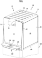
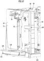
- a beverage preparation device 10 in the form of a water dispenser 12 is shown schematically as an example. It is designed for the treatment of drinking water and is preferably designed to be pipe-connected.
- the water dispenser 12 comprises a liquid inlet 14, optionally several liquid inlets can also be provided, and a beverage outlet 16, from which treated drinking water 18 can be filled into a container 20, for example a glass.
- the beverage outlet 16 is part of a beverage dispensing device 22 which can optionally include a beverage outlet valve 24 .
- the beverage outlet valve 24 is designed in particular to control the delivery of a beverage and can be designed to be controlled and/or regulated electrically or pneumatically.
- an electromagnetic drive 26 for opening and closing the beverage outlet valve 24 can be provided.
- the liquid inlet 14 and the beverage outlet 16 are fluidically connected to one another via a liquid line network 28 . It comprises a plurality of connecting lines 30 which fluidly connect individual components of the beverage preparation device 10 through which water flows.
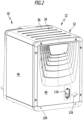
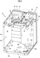
- the water dispenser 10 further includes a housing 32 having a removable housing top cover 34 forming one of a plurality of housing sections 36 .
- the housing parts 36 are, in particular, self-supporting plastic components 38 made of plastic, for example by injection molding.
- the cover 44 can be designed, for example, in the form of a glass pane.
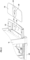
- a component or valve carrier 54 forms part of the housing 32. It is self-supporting and connected on the one hand to the intermediate housing part 50 and on the other hand to the housing rear wall 40, for example screwed and/or latched.
- the housing base 50, the housing rear wall 40, the housing intermediate part 50 and the valve carrier 54 form a self-supporting frame 56 of the water dispenser 12, on which its further housing parts 36 and the components required for its operation are arranged.
- the right housing wall 46 and the left housing wall 48 can be removed, as can the housing top cover 34, without this having a significant effect on the stability of the water dispenser 12.
- a housing interior 58 defined by the housing 32 can thus be easily opened in order to be able to access components arranged therein essentially freely.
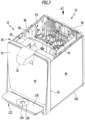
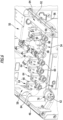
- valve carrier 54 is positioned in the housing interior 58 in such a way that control and/or regulating valves 64 can be inserted directly from above into valve receptacles 60 correspondingly provided on the valve carrier 54 .
- the control and/or regulating valves 64 are preferably in the form of electrically controllable valves and include a valve drive 66.
- an electromagnetic valve drive 66 can be provided for opening and closing the control and/or regulating valves 64.
- the control and/or regulating valves 64 each have a valve inlet 68 and a valve outlet 70 .
- the control and/or regulating valves 64 are arranged on the valve carrier 54 in the valve receptacles 60 in such a way that their valve inlets 68 and their valve outlets 80 point in the direction of a front side 72 or a rear side 74 of the housing.
- the valve drives 66 are arranged between the valve inlets 68 and the valve outlets 70 on the one hand and the housing cover 34 on the other hand.
- control and/or regulating valves 64 or a pressure switch 76 in a pressure switch receptacle 62 that is inserted into a pressure switch receptacle 62 This arrangement simplifies the assembly of the control and/or regulating valves 64 and also their maintenance and, if necessary, repair. Preferably, all components that require intensive maintenance can be arranged so that they are easily accessible for a user.
- an electrical connection line 78 to a preferably central control and/or regulation device 80 is shown schematically for a pressure switch 76 and a control and/or regulating valve 64, from which at least some, preferably all, of the electrically controllable and/or regulated Components of the water dispenser 12 can be controlled.
- control and/or regulating device 80 can be operatively connected to an actuating element 82 via a further connecting line 78, so that an operator, as a result of actuating the actuating element 82, for example embodied in the form of a push button or pressure switch, and valve closing processes and optionally also pump cycles by the control and/or regulating device 80 and/or in particular the drive 26 of the beverage outlet valve 24 is actuated by it in such a way that drinking water 18 flows out of the beverage outlet 16 into the container 20.
- Valve carrier 54 also has a cable routing device 84 comprising two cable ducts 86, which are formed on the end face of valve carrier 54 and are aligned transversely to a longitudinal direction defined by this , ie parallel to the cable ducts 86.
- the valve carrier 54 and the cable ducts 86 together form a one-piece component.
- fastening elements 88 are arranged on the valve receptacles 60 and the pressure switch receptacles 62, preferably in the form of latching elements 90 protruding essentially in the direction of the housing cover 34 or educated. They make it possible to clip the control and/or regulating valves 64 into the valve receptacles 60 or the pressure switch 76 into a pressure switch receptacle 62 from above. Further fastening elements for fixing the components described on the valve carrier 54 are then not absolutely necessary.
- Electrical connecting lines 78 of the beverage preparation device 10 can be routed in the cable ducts 86 in a particularly space-saving and nevertheless clear manner and routed to the electrically controllable and/or adjustable components arranged on the valve carrier 54 .
- cable holding elements can also be arranged or formed on the housing parts 36 , for example in the form of cable duct-like recesses or cable clips formed integrally with the respective housing part 36 .
- these make it possible to lay connecting lines and/or cables that can be laid to form the liquid line network 28 or for the electrically conductive connection of electrically actuated or controllable components of the water dispenser 12 .
- the cable holding elements can optionally also be in the form of tabs or hooks. Projections 94 and 98 pointing into the housing interior 58 are used to connect hooks, rails and/or guides for holding the housing walls 46, 48.
- the projections 94, 98 are preferably hollow so that they are not visible on an external visible side of the housing base 52 .
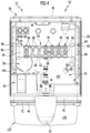
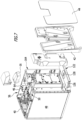
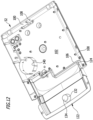
- the housing base 52 is at least partially trough-shaped and includes a liquid collection container 100. This is formed integrally with the housing base 52.
- a case bottom surface 102 of the case bottom 52 faces toward the case top cover 34 and is recessed toward the case cover 34 relative to a case bottom exterior 104 .
- the liquid collection container 100 at least partially surrounds the housing bottom surface 102 . As in figure 12 to recognize, the liquid collection container 100 surrounds the housing bottom surface 102 in a substantially U-shape. Both the liquid collection container 100 and the housing bottom surface 102 are delimited by a bulkhead 106 projecting in the direction of the housing cover 34 in the manner of a flange.
- the liquid collection container 100 has a liquid collection container outlet 108 . This is designed in the form of a bore, which is arranged below the housing rear wall 40 and can be closed with a plug, not shown in the figures.
- a detector 110 for determining a filling level of liquid 112 collected in the liquid collecting container 100 is provided.
- Detector 112 can include, in particular, a reed contact that can be actuated by means of a float, which is connected to control and/or regulating device 80 via an electrically conductive connecting line 78, for example in order to deactivate water dispenser 12 or, in particular, an electromagnetically actuatable inlet valve 114, which is connected to the liquid inlet 14 downstream, to prevent the liquid collection container 100 from overflowing.
- the left and/or right side wall of the housing are designed in such a way that they can be removed without dismantling other parts of the housing 32 .
- a passage 116 in the form of a circular opening is preferably arranged on the housing rear wall 40 and is used for passage of the liquid inlet 14 .
- an opening 118 for a mains connection device 120 for electrically conductive connection to a mains supply can also be provided on the housing rear wall 40 .
- the mains connection device 120 can be designed in particular in the form of a mains plug connection socket, which can be connected to a first end of a standardized mains connection cable, the other end of which can be inserted into a socket, for example a domestic socket.
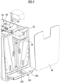
- the water dispenser 12 also includes a drip tray 122 which is designed like a drawer and can be pushed partially into the housing 52 . For emptying, the drip tray 122 can be pulled out completely from a recess 124 provided for this purpose, which is formed in the housing floor 52 .
- the drip tray 122 is arranged in the direction of gravity below the beverage outlet 16 and below the cover 44.
- a drip tray cover 126 is used to close the part of the drip tray 122 protruding from the housing 52.
- the drip tray cover 126 has a circular drip tray cover opening 128, which is formed in the center of an annular drainage surface 130 that slopes in the direction of the drip tray cover opening 128.
- a drip body 132 pointing in the direction of the drip tray cover 126 is formed in one piece with the drip tray 122 . It essentially has the shape of a truncated cone and ends in a trickling filter surface 134 which is slightly convexly curved in the direction of the beverage outlet 16 .
- the dripping body 132 is arranged and designed in such a way that an annular opening 136 is formed between the dripping body surface 134 and the drip tray cover opening 128 . If liquid 18 drips onto the drainage surface 130, it is guided through the opening 136 into the drip tray 122. If a drop of liquid hits the dripping body surface 134, then it is deflected in a defined manner and also guided through the opening 136 into the drip tray 122.
- the liquid inlet 14 is designed in particular in the form of a water inlet for connection to a tap 138 of an external drinking water network 140 . In particular, this makes it possible to use the water dispenser 12 to continuously prepare drinking water 18 and make it available.
- the water dispenser 12 can optionally include a filter device 142 with which water flowing through the liquid inlet 14 is filtered out of the drinking water network 140 .
- the filter device 142 can in particular comprise at least one water filter 144. This can be designed in particular in the form of a water filter cartridge that can be replaced at regular intervals.
- the water dispenser 12 can optionally include a sterilization device 146 for sterilizing the water flowing through the liquid line network 28 .
- the sterilization device 146 can include a UV light source 148 for irradiating the liquid flowing through the liquid line network 28 with UV radiation.
- a thermal hygienization device can also be provided, with which a thermal hygienization of the water dispenser can be carried out.
- hot water is circulated for a specific time in the water dispenser, in particular in the liquid line network 28, and then flushed out.
- a chemical cleaning of the water dispenser in which a cleaning solution is introduced into the liquid line network 28 and rinsed out again after a certain dwell time in the water dispenser.
- the water dispenser 12 can optionally also include a carbon dioxide mixing device 150 with a carbon dioxide outlet 152 for charging the liquid flowing in the liquid line network 28 with carbon dioxide.
- the carbon dioxide outlet 152 is in fluid connection with the liquid line network 28 .
- the carbon dioxide mixing device 150 can comprise an outlet valve 154 for controlling and/or regulating a carbon dioxide flow through the carbon dioxide outlet 152 .
- outlet valve 154 can be controlled by control and/or regulation device 80, for example depending on the actuation of an actuating element 156 provided for this purpose, which is operatively connected to control and/or regulation device 80.
- the carbon dioxide can also be admixed in a different way, namely purely mechanically via the secondary pressure set on a pressure reducer and the water pressure present on a mixer.
- a carbon dioxide reservoir 158 can be arranged either externally, possibly in a vertical column 166, or internally, for example on a special receptacle with an integrated pressure reducer.
- the special receptacle with the pressure reducer can be installed behind the door formed by the front wall 42 in the intermediate housing part 50 or can be screwed on at the top.
- the carbon dioxide reservoir 158 can in particular be designed in the form of a carbon dioxide compressed gas cylinder which is in fluid communication with the carbon dioxide mixing device 150 via a pressure line 162 .
- the beverage preparation device 10 can also include a heating device, not shown in the figures, for heating water and/or a beverage prepared ready for dispensing, for example in the form of a boiler, which is inserted into a receptacle 160 provided for it on the housing base 52.
- a heating device not shown in the figures, for heating water and/or a beverage prepared ready for dispensing, for example in the form of a boiler, which is inserted into a receptacle 160 provided for it on the housing base 52.
- the intermediate housing part 50 is preferably embodied in the form of a component carrier 164, on which one or more components of the water dispenser 12, in particular the disinfection device 146, the carbon dioxide mixing device 150 and/or the central control and/or regulation device 80, can be arranged.
- the water dispenser 12 can be used in particular as a tabletop device in the figure 1 illustrated designs are set up or arranged on the pedestal 166, which can be used in particular to accommodate a supply of carbon dioxide bottles or beverage cups.
Claims (15)
- Appareil de préparation de boissons (10) comprenant au moins une entrée de liquide, un dispositif de distribution de boisson comportant au moins une sortie de liquide (16), un réseau de conduites de liquide (28) reliant sur le plan fluidique, ladite au moins une entrée de liquide (14) et ladite au moins une sortie de liquide (16), et un carter (32), appareil de préparation de boissons dans lequel le carter (32) comporte un couvercle de carter supérieur (34), et sous le couvercle de carter supérieur (34) est disposé un support de vannes (54) sur lequel sont agencées au moins deux vannes de commande et/ou de régulation (64) de l'appareil de préparation de boissons (10), qui sont librement accessibles après avoir retiré le couvercle de carter supérieur (34), et dans lequel un fond de carter (52) est réalisé sensiblement sous forme de bac et comporte, formé intégralement avec celui-ci, un récipient de collecte de liquide (100), caractérisé en ce que le fond de carter (52) présente une surface de fond de carter (102), qui est en retrait en direction du couvercle de carter supérieur (34), par rapport à un côté extérieur de fond de carter (104), qui est orienté dans une direction s'éloignant du couvercle de carter supérieur (34), en ce que le réservoir de collecte de liquide (100) entoure au moins partiellement ladite surface de fond de carter (102), et en ce que le support de vannes (54) est fixé à une paroi arrière de carter (40) d'une part, et à une pièce intermédiaire de carter (50) autoporteuse et maintenue sur le fond de carter (52), ou bien à une paroi avant de carter (42) d'autre part.
- Appareil de préparation de boissons selon la revendication 1, caractérisé en ce quea) le carter (32) est réalisé sous la forme d'un carter autoporteur (32), le carter (32) comporte une pluralité de pièces de carter (36) fabriquées en une matière plastique, et au moins une partie des pièces de carter (36) comportent des dispositifs de maintien de composants pour assurer le maintien d'autres composants formant l'appareil de préparation de boissons (10),
et/oub) le carter (32) est réalisé au moins en partie par des pièces de matière plastique (38) autoporteuses. - Appareil de préparation de boissons selon la revendication 2, caractérisé en ce quea) les pièces de carter (36) comprennent notamment le support de vannes, le couvercle de carter supérieur (34), une paroi arrière de carter (40), une paroi avant de carter (42), une paroi latérale de carter droite et gauche (46, 48), une pièce intermédiaire de carter (50) agencée entre la paroi avant de carter (42) et la paroi arrière de carter (40), et un fond de carter (52),
et/oub) sur au moins une partie des pièces de carter (36) sont agencés ou formés des éléments de maintien de câbles (92, 94) pour fixer des conducteurs de branchement et/ou des câbles, notamment des éléments de maintien de câbles (92, 94) formés intégralement avec lesdites pièces, les éléments de maintien de câbles (92, 94) étant notamment réalisés sous la forme de pattes ou de crochets. - Appareil de préparation de boissons selon l'une des revendications précédentes, caractérisé en ce que lesdites au moins deux vannes de commande et/ou de régulation (64)a) sont réalisées sous la forme de vannes pouvant être commandées électriquement,
et/oub) présentent un entrainement de vanne (66), notamment électromagnétique, pour assurer l'ouverture et/ou la fermeture de celles-ci. - Appareil de préparation de boissons selon l'une des revendications précédentes, caractérisé en ce que lesdites au moins deux vannes de commande et/ou de régulation (64) présentent une entrée de vanne (68) et une sortie de vanne (70), qui sont orientées dans des directions mutuellement opposées.
- Appareil de préparation de boissons selon la revendication 5, caractérisé en ce quea) lesdites au moins deux vannes de commande et/ou de régulation (64) sont agencées sur le support de vannes (54) de manière telle, que leurs entrées de vanne (68) et leurs sorties de vanne (80) soient dirigées en direction d'un côté arrière de carter (74) du carter (32) ou en direction d'un côté avant de carter (72) du carter,
et/oub) ladite au moins une vanne de commande et/ou de régulation (64) est agencée sur le support de vannes (54) de manière telle, que l'entrainement de vanne (66) soit agencé entre l'entrée de vanne (68) et la sortie de vanne (70) d'une part et le couvercle de carter supérieur (34) d'autre part. - Appareil de préparation de boissons selon l'une des revendications précédentes, caractérisé en ce quea) sur le support de vannes (54) est agencé au moins un contacteur manométrique (76) interagissant ou relié avec un réseau de conduites de liquide (28) et/ou un réseau de conduites de CO2 (162),
et/oub) le support de vannes (54) présente un dispositif de guidage de câbles (84), et des conducteurs de raccordement électrique (78) de l'appareil de préparation de boissons (10), vers des composants commandés électriquement agencés notamment sur le support de vannes (54), sont posés sur ou dans le dispositif de guidage de câbles (84),
et/ouc) le support de vannes (54) définit un axe longitudinal, qui s'étend transversalement à une ligne de liaison entre un côté avant de carter (72) et un côté arrière de carter (74) du carter (32),
et/oud) le réservoir de collecte de liquide (100) présente une sortie de réservoir de collecte de liquide (108) pour vider le liquide qui y a été collecté,
et/oue) l'appareil de préparation de boissons comporte un détecteur (110) pour déterminer un niveau de remplissage de liquide (112) collecté dans le réservoir de collecte de liquide (100). - Appareil de préparation de boissons selon l'une des revendications précédentes, caractérisé en ce quea) la paroi latérale de carter droite et/ou gauche (46, 48) sont agencées de manière amovible, sans démonter d'autres pièces du carter (32), sur les autres pièces du carter (32) formant le carter (32),
et/oub) la paroi arrière de carter (40) présente un passage de traversée pour l'entrée de liquide (14) et/ou un évidement de passage pour un dispositif de raccordement au réseau (120) en vue d'assurer le branchement électrique à un réseau de courant,
le dispositif de raccordement au réseau (120) étant notamment réalisé sous la forme d'une prise de branchement de fiche de raccordement au réseau. - Appareil de préparation de boissons selon l'une des revendications précédentes, caractérisé par un bac d'égouttage (122), qui est agencé sous la sortie de boissons.
- Appareil de préparation de boissons selon la revendication 9, caractérisé en ce que le bac d'égouttage (122)a) peut être inséré, à la manière d'un tiroir, au moins partiellement dans le carter (52), et peut en être retiré complètement pour le vider,
et/oub) comporte un corps d'égouttage avec une surface de corps d'égouttage (134) de courbure convexe orientée en direction de la sortie de boisson (16),
et/ouc) comprend un couvercle de bac d'égouttage (126), qui ferme au moins partiellement la partie du bac d'égouttage (122) faisant saillie du carter (52), et présente un passage de couvercle de bac d'égouttage (128),le corps d'égouttage (132) étant notamment agencé de manière à ce que soit formée une ouverture de forme annulaire entre la surface de corps d'égouttage (134) et le passage de couvercle de bac d'égouttage (128). - Appareil de préparation de boissons selon l'une des revendications précédentes, caractérisé en ce quea) l'appareil de préparation de boissons comporte une vanne de sortie de boisson (24) associée à la sortie de boissons (16), pour commander une distribution de boisson, la vanne de sortie de boisson (24) étant notamment réalisée sous la forme d'une vanne pouvant être commandée et/ou régulée par voie électrique,
et/oub) ladite au moins une entrée de liquide (14) étant réalisée sous la forme d'une entrée d'eau destinée à être reliée à un point de branchement (138) d'un réseau d'eau potable externe (140),
et/ouc) l'appareil de préparation de boissons comprend au moins un dispositif de filtre (142) pour filtrer le liquide pénétrant à travers ladite au moins une entrée de liquide (14),
le dispositif de filtre (142) comprenant notamment au moins un filtre d'eau (144),
et/oud) l'appareil de préparation de boissons comprend au moins un dispositif purificateur (146) pour purifier le liquide s'écoulant à travers le réseau de conduites de liquide (28), le dispositif de purification (146) comprenant une source lumineuse d'UV (148) pour irradier le liquide s'écoulant à travers le réseau de conduites de liquide, avec un rayonnement UV. - Appareil de préparation de boissons selon l'une des revendications précédentes, caractérisé par un dispositif de mélange de dioxyde de carbone (150) avec une sortie de dioxyde de carbone (152) pour alimenter le liquide s'écoulant dans le réseau de conduites de liquide (28), avec du dioxyde de carbone.
- Appareil de préparation de boissons selon la revendication 12, caractérisé en ce quea) la sortie de dioxyde de carbone (152) est en liaison fluidique avec le réseau de conduites de liquide (28),
et/oub) le dispositif de mélange de dioxyde de carbone (150) comprend une vanne de sortie (154) pour commander et/ou réguler un écoulement de dioxyde de carbone à travers la sortie de dioxyde de carbone (152),
et/ouc) le dispositif de mélange de dioxyde de carbone (150) comprend un accumulateur de dioxyde de carbone (158), notamment sous la forme d'une cartouche de dioxyde de carbone sous pression. - Appareil de préparation de boissons selon l'une des revendications précédentes, caractérisé para) un dispositif centralisé de commande et/ou de régulation (80) pour commander et ou réguler des composants de l'appareil de préparation de boissons (10), qui peuvent notamment être actionnés par voie électrique,
et/oub) un support de composants (164) sur lequel sont agencés ou peuvent être agencés les autres composants, qui forment l'appareil de préparation de boissons (10). - Appareil de préparation de boissons selon l'une des revendications précédentes, caractérisé en ce quea) les autres composants formant l'appareil de préparation de boissons (10) comprennent notamment lesdites au moins deux vannes de commande et/ou de régulation (64), ledit au moins un contacteur manométrique (76), le dispositif de purification (146), le dispositif de mélange de dioxyde de carbone (150) et/ou le dispositif centralisé de commande et/ou de régulation (80),
et/oub) l'appareil de préparation de boissons (10) est réalisé sous la forme d'un distributeur d'eau (12), notamment sous la forme d'un distributeur d'eau (12) relié au réseau, pour la distribution d'eau potable (18).
Applications Claiming Priority (1)
| Application Number | Priority Date | Filing Date | Title |
|---|---|---|---|
| PCT/EP2014/074339 WO2016074711A1 (fr) | 2014-11-12 | 2014-11-12 | Appareil de préparation de boissons |
Publications (3)
| Publication Number | Publication Date |
|---|---|
| EP3218299A1 EP3218299A1 (fr) | 2017-09-20 |
| EP3218299B1 EP3218299B1 (fr) | 2020-01-01 |
| EP3218299B2 true EP3218299B2 (fr) | 2023-03-22 |
Family
ID=51897264
Family Applications (1)
| Application Number | Title | Priority Date | Filing Date |
|---|---|---|---|
| EP14796764.0A Active EP3218299B2 (fr) | 2014-11-12 | 2014-11-12 | Appareil de préparation de boissons |
Country Status (2)
| Country | Link |
|---|---|
| EP (1) | EP3218299B2 (fr) |
| WO (1) | WO2016074711A1 (fr) |
Citations (20)
| Publication number | Priority date | Publication date | Assignee | Title |
|---|---|---|---|---|
| DE1451015A1 (de) † | 1963-07-31 | 1969-01-23 | Siemens Elektrogeraete Gmbh | Mit einer Kompressionskaeltemaschine ausgeruesteter Kuehlschrank |
| WO1990012752A1 (fr) † | 1989-04-25 | 1990-11-01 | Ebco Manufacturing Company | Distributeur de boissons avec panneaux exterieurs en resine synthetique rattaches |
| DE4142331A1 (de) † | 1991-12-20 | 1993-07-08 | Bosch Siemens Hausgeraete | Rost fuer einen einfuellbereich eines getraenkeautomaten |
| WO1995021750A1 (fr) † | 1994-02-15 | 1995-08-17 | Fischerwerke Artur Fischer Gmbh & Co. Kg | Dispositif de maintien de recipient a liquide, notamment a monter dans des vehicules a moteur |
| EP0774632A2 (fr) † | 1995-11-15 | 1997-05-21 | Bosch-Siemens HausgerÀ¤te GmbH | Appareil frigorifique |
| JPH1043736A (ja) † | 1996-05-25 | 1998-02-17 | Samsung Electron Co Ltd | 配水器 |
| US5889684A (en) † | 1996-10-18 | 1999-03-30 | Waterlogic International Ltd. | Computer-controlled heated and/or cooled liquid dispenser |
| US6010043A (en) † | 1998-03-23 | 2000-01-04 | Draw Box, Incorporated | Self-contained, portable beverage dispensing system |
| US20030217564A1 (en) † | 2001-04-30 | 2003-11-27 | Jones Brian C. | Beverage dispenser |
| US20050279689A1 (en) † | 2004-04-02 | 2005-12-22 | Tana Industries (1991) Ltd. | Water dispenser and filter cartridge for use therein |
| US20090236364A1 (en) † | 2008-03-20 | 2009-09-24 | Imi Cornelius Inc. | Apparatus for attaching a drip tray to a beverage dispenser |
| US20090283543A1 (en) † | 2008-05-15 | 2009-11-19 | Schroeder Industries, Inc. D/B/A Schroeder America | Flow Control and Manifold Assembly |
| US7823501B2 (en) † | 2004-10-18 | 2010-11-02 | Koninklijke Philips Electronics N.V. | Beverage supplying device having a drip tray comprising a convex droplet landing surface |
| EP2365587A1 (fr) † | 2010-01-15 | 2011-09-14 | G.V.P. Elettronica S.r.l. | Boîte de distribution électrique pour l'alimentation des circuits d'un appareil électrique |
| US8091469B2 (en) † | 2005-06-07 | 2012-01-10 | Nestec S.A. | Beverage machine with drip tray device for recipients of different heights |
| KR20130067114A (ko) † | 2011-12-13 | 2013-06-21 | 이은영 | 누수 방지 기능이 향상된 음용수 공급장치 |
| US20130206793A1 (en) † | 2012-02-14 | 2013-08-15 | Schroeder Industries, Inc. D/B/A Schroeder America | Handle initiated electromechanical multi-flavor beverage dispenser |
| US20130277394A1 (en) † | 2012-04-18 | 2013-10-24 | Schroeder Industries, Inc. D/B/A Schroeder America | Moveable roll around self-contained ice cooled beverage dispensing apparatus |
| EP2664880A2 (fr) † | 2012-05-17 | 2013-11-20 | Samsung Electronics Co., Ltd | Réfrigérateur comprenant un appareil pour produire de l'eau gazéifiée |
| JP5583292B1 (ja) † | 2014-02-07 | 2014-09-03 | 株式会社コスモライフ | ウォーターサーバー |
Family Cites Families (9)
| Publication number | Priority date | Publication date | Assignee | Title |
|---|---|---|---|---|
| US3726102A (en) * | 1971-08-03 | 1973-04-10 | C Parks | Icy beverage machine |
| US5190188A (en) | 1987-12-04 | 1993-03-02 | The Coca-Cola Company | Convertible beverage dispenser |
| GB2247848B (en) * | 1990-08-17 | 1994-05-11 | Whitlenge Drink Equipment Ltd | Improvements relating to apparatus for dispensing drinks |
| US6439428B1 (en) * | 2000-08-03 | 2002-08-27 | Lancer Partnership L.L.P. | Dispenser with features for enhanced maintainability |
| HU225735B1 (en) | 2001-04-06 | 2007-07-30 | Scott Nicol | Carbonation apparatus and method for water carbonation |
| US7926413B2 (en) | 2006-05-19 | 2011-04-19 | Bunn-O-Matic Corporation | Beverage server with a drip tray assembly |
| US9271604B2 (en) * | 2008-11-10 | 2016-03-01 | Automatic Bar Controls, Inc. | Manifold system for beverage dispenser |
| CA2858775A1 (fr) * | 2011-12-12 | 2013-06-20 | Nestec S.A. | Plateau d'egouttage pour distributeur de boissons |
| US8881949B2 (en) * | 2012-01-25 | 2014-11-11 | Schroeder Industries, Inc. | Modular beverage dispenser having a build-in cold plate and carbonator |
-
2014
- 2014-11-12 WO PCT/EP2014/074339 patent/WO2016074711A1/fr active Application Filing
- 2014-11-12 EP EP14796764.0A patent/EP3218299B2/fr active Active
Patent Citations (20)
| Publication number | Priority date | Publication date | Assignee | Title |
|---|---|---|---|---|
| DE1451015A1 (de) † | 1963-07-31 | 1969-01-23 | Siemens Elektrogeraete Gmbh | Mit einer Kompressionskaeltemaschine ausgeruesteter Kuehlschrank |
| WO1990012752A1 (fr) † | 1989-04-25 | 1990-11-01 | Ebco Manufacturing Company | Distributeur de boissons avec panneaux exterieurs en resine synthetique rattaches |
| DE4142331A1 (de) † | 1991-12-20 | 1993-07-08 | Bosch Siemens Hausgeraete | Rost fuer einen einfuellbereich eines getraenkeautomaten |
| WO1995021750A1 (fr) † | 1994-02-15 | 1995-08-17 | Fischerwerke Artur Fischer Gmbh & Co. Kg | Dispositif de maintien de recipient a liquide, notamment a monter dans des vehicules a moteur |
| EP0774632A2 (fr) † | 1995-11-15 | 1997-05-21 | Bosch-Siemens HausgerÀ¤te GmbH | Appareil frigorifique |
| JPH1043736A (ja) † | 1996-05-25 | 1998-02-17 | Samsung Electron Co Ltd | 配水器 |
| US5889684A (en) † | 1996-10-18 | 1999-03-30 | Waterlogic International Ltd. | Computer-controlled heated and/or cooled liquid dispenser |
| US6010043A (en) † | 1998-03-23 | 2000-01-04 | Draw Box, Incorporated | Self-contained, portable beverage dispensing system |
| US20030217564A1 (en) † | 2001-04-30 | 2003-11-27 | Jones Brian C. | Beverage dispenser |
| US20050279689A1 (en) † | 2004-04-02 | 2005-12-22 | Tana Industries (1991) Ltd. | Water dispenser and filter cartridge for use therein |
| US7823501B2 (en) † | 2004-10-18 | 2010-11-02 | Koninklijke Philips Electronics N.V. | Beverage supplying device having a drip tray comprising a convex droplet landing surface |
| US8091469B2 (en) † | 2005-06-07 | 2012-01-10 | Nestec S.A. | Beverage machine with drip tray device for recipients of different heights |
| US20090236364A1 (en) † | 2008-03-20 | 2009-09-24 | Imi Cornelius Inc. | Apparatus for attaching a drip tray to a beverage dispenser |
| US20090283543A1 (en) † | 2008-05-15 | 2009-11-19 | Schroeder Industries, Inc. D/B/A Schroeder America | Flow Control and Manifold Assembly |
| EP2365587A1 (fr) † | 2010-01-15 | 2011-09-14 | G.V.P. Elettronica S.r.l. | Boîte de distribution électrique pour l'alimentation des circuits d'un appareil électrique |
| KR20130067114A (ko) † | 2011-12-13 | 2013-06-21 | 이은영 | 누수 방지 기능이 향상된 음용수 공급장치 |
| US20130206793A1 (en) † | 2012-02-14 | 2013-08-15 | Schroeder Industries, Inc. D/B/A Schroeder America | Handle initiated electromechanical multi-flavor beverage dispenser |
| US20130277394A1 (en) † | 2012-04-18 | 2013-10-24 | Schroeder Industries, Inc. D/B/A Schroeder America | Moveable roll around self-contained ice cooled beverage dispensing apparatus |
| EP2664880A2 (fr) † | 2012-05-17 | 2013-11-20 | Samsung Electronics Co., Ltd | Réfrigérateur comprenant un appareil pour produire de l'eau gazéifiée |
| JP5583292B1 (ja) † | 2014-02-07 | 2014-09-03 | 株式会社コスモライフ | ウォーターサーバー |
Non-Patent Citations (3)
| Title |
|---|
| "Kärcher Wasserspender WPD 100, 200 und 600", YOUTUBE, 14 October 2014 (2014-10-14), Retrieved from the Internet <URL:https://www.voutube.com/watch?v=ExhI8RMR8iM> [retrieved on 20200924] † |
| Buch Fries, O. et al., "Getränkeschankanlagen; Praxishandbuch und DIN-Normen" Berlin: Beuth Verlag GmbH, 2002, Ed. 1 † |
| W. BEITZ UND K.-H. GROTE: "DUBBEL TASCHENBUCH FÜR DEN MASCHINENBAU", 1997, Berlin , Heidelberg, article "Kunststoffe", pages: E66 - E72 † |
Also Published As
| Publication number | Publication date |
|---|---|
| EP3218299A1 (fr) | 2017-09-20 |
| EP3218299B1 (fr) | 2020-01-01 |
| WO2016074711A1 (fr) | 2016-05-19 |
Similar Documents
| Publication | Publication Date | Title |
|---|---|---|
| EP1878370B9 (fr) | Dispositif de nettoyage | |
| EP2272409B1 (fr) | Machine de préparation de boissons et procédé de nettoyage d'une machine de préparation de boissons | |
| EP2102535A2 (fr) | Distributeur d'eau et dispositif de distribution de boissons équipé d'un distributeur d'eau | |
| WO2008006623A2 (fr) | Dispositif pour acheminer du lait | |
| EP2446079A1 (fr) | Lave-linge à commande automatique pour agent de traitement de linge | |
| EP3027818A1 (fr) | Utilisation d'un dispositif de distribution d'eau dans un élément sous-évier pour distribuer de l'eau potable à des appareils domestiques à circulation d'eau | |
| EP0695503B1 (fr) | Four pour cuire à la vapeur | |
| DE69908137T2 (de) | Vorrichtung zum Abgeben von Flüssigkeit aus nebeneinander angeordneten Behältern | |
| EP3218299B2 (fr) | Appareil de préparation de boissons | |
| EP0047408B1 (fr) | Procédé pour vider, nettoyer et désinfecter des récipients hygiéniques dans le domaine hospitalier, sans contamination de la partie extérieure de l'appareil utilisé pour sa mise en oeuvre | |
| EP0807428B1 (fr) | Générateur de vapeur pour sauna | |
| DE102009054161B4 (de) | Vorrichtung zum Reinigen und Desinfizieren von Reinigungsgut und Verfahren zur Desinfektion einer Vorrichtung der vorgenannten Art | |
| DE19526215A1 (de) | Gerät zur Erzeugung und Abgabe verschiedener Post-Mix-Getränke sowie Verfahren zum Betrieb eines solchen Gerätes | |
| DE10055137A1 (de) | Einspeisungsbauteil für Gase und Flüssigkeiten das es ermöglicht über den Flüssigkeitsdruck den Gasestrom freizugeben innerhalb des Einspeisungsbauteil für Gase und Flüssigkeiten | |
| DE102011103142B3 (de) | Vorrichtung zum Reinigen und Desinfizieren von Reinigungsgut und Verfahren zur Desinfektion einer Vorrichtung der vorgenannten Art | |
| DE102011050350A1 (de) | Getränkedispenser | |
| EP1027277B1 (fr) | Distributeur de liquide mobile | |
| EP0580111B1 (fr) | Humidificateur pour meubles de vente | |
| DE102012209297B4 (de) | Wasserbehälter eines Sterilisationsgeräts | |
| DE102014119614A1 (de) | Vorrichtung zum Spenden von Flüssigkeiten | |
| WO1997030938A1 (fr) | Appareil modulaire de traitement de l'eau | |
| DE102018104395A1 (de) | Haushaltsgerät | |
| DE3322077A1 (de) | Vorrichtung zur erzeugung eines dampfstrahles | |
| EP1916928B1 (fr) | Dispositif de cuisson à la vapeur | |
| DE3644519A1 (de) | Vorrichtung zum zubereiten von cappuccino |
Legal Events
| Date | Code | Title | Description |
|---|---|---|---|
| STAA | Information on the status of an ep patent application or granted ep patent |
Free format text: STATUS: THE INTERNATIONAL PUBLICATION HAS BEEN MADE |
|
| PUAI | Public reference made under article 153(3) epc to a published international application that has entered the european phase |
Free format text: ORIGINAL CODE: 0009012 |
|
| STAA | Information on the status of an ep patent application or granted ep patent |
Free format text: STATUS: REQUEST FOR EXAMINATION WAS MADE |
|
| 17P | Request for examination filed |
Effective date: 20170512 |
|
| AK | Designated contracting states |
Kind code of ref document: A1 Designated state(s): AL AT BE BG CH CY CZ DE DK EE ES FI FR GB GR HR HU IE IS IT LI LT LU LV MC MK MT NL NO PL PT RO RS SE SI SK SM TR |
|
| AX | Request for extension of the european patent |
Extension state: BA ME |
|
| RIN1 | Information on inventor provided before grant (corrected) |
Inventor name: SEUTTER, MICHAEL Inventor name: GUEERS, MATTHIAS |
|
| DAX | Request for extension of the european patent (deleted) | ||
| RAP1 | Party data changed (applicant data changed or rights of an application transferred) |
Owner name: ALFRED KAERCHER SE & CO. KG |
|
| GRAJ | Information related to disapproval of communication of intention to grant by the applicant or resumption of examination proceedings by the epo deleted |
Free format text: ORIGINAL CODE: EPIDOSDIGR1 |
|
| GRAP | Despatch of communication of intention to grant a patent |
Free format text: ORIGINAL CODE: EPIDOSNIGR1 |
|
| GRAP | Despatch of communication of intention to grant a patent |
Free format text: ORIGINAL CODE: EPIDOSNIGR1 |
|
| STAA | Information on the status of an ep patent application or granted ep patent |
Free format text: STATUS: GRANT OF PATENT IS INTENDED |
|
| INTG | Intention to grant announced |
Effective date: 20190327 |
|
| RIN1 | Information on inventor provided before grant (corrected) |
Inventor name: SEUTTER, MICHAEL Inventor name: GUEERS, MATTHIAS |
|
| GRAJ | Information related to disapproval of communication of intention to grant by the applicant or resumption of examination proceedings by the epo deleted |
Free format text: ORIGINAL CODE: EPIDOSDIGR1 |
|
| STAA | Information on the status of an ep patent application or granted ep patent |
Free format text: STATUS: REQUEST FOR EXAMINATION WAS MADE |
|
| INTC | Intention to grant announced (deleted) | ||
| GRAP | Despatch of communication of intention to grant a patent |
Free format text: ORIGINAL CODE: EPIDOSNIGR1 |
|
| STAA | Information on the status of an ep patent application or granted ep patent |
Free format text: STATUS: GRANT OF PATENT IS INTENDED |
|
| GRAS | Grant fee paid |
Free format text: ORIGINAL CODE: EPIDOSNIGR3 |
|
| INTG | Intention to grant announced |
Effective date: 20191009 |
|
| GRAA | (expected) grant |
Free format text: ORIGINAL CODE: 0009210 |
|
| STAA | Information on the status of an ep patent application or granted ep patent |
Free format text: STATUS: THE PATENT HAS BEEN GRANTED |
|
| AK | Designated contracting states |
Kind code of ref document: B1 Designated state(s): AL AT BE BG CH CY CZ DE DK EE ES FI FR GB GR HR HU IE IS IT LI LT LU LV MC MK MT NL NO PL PT RO RS SE SI SK SM TR |
|
| REG | Reference to a national code |
Ref country code: GB Ref legal event code: FG4D Free format text: NOT ENGLISH |
|
| REG | Reference to a national code |
Ref country code: CH Ref legal event code: EP Ref country code: CH Ref legal event code: NV Representative=s name: ISLER AND PEDRAZZINI AG, CH Ref country code: AT Ref legal event code: REF Ref document number: 1219570 Country of ref document: AT Kind code of ref document: T Effective date: 20200115 |
|
| REG | Reference to a national code |
Ref country code: IE Ref legal event code: FG4D Free format text: LANGUAGE OF EP DOCUMENT: GERMAN |
|
| REG | Reference to a national code |
Ref country code: DE Ref legal event code: R096 Ref document number: 502014013399 Country of ref document: DE |
|
| REG | Reference to a national code |
Ref country code: NL Ref legal event code: MP Effective date: 20200101 |
|
| REG | Reference to a national code |
Ref country code: LT Ref legal event code: MG4D |
|
| PG25 | Lapsed in a contracting state [announced via postgrant information from national office to epo] |
Ref country code: CZ Free format text: LAPSE BECAUSE OF FAILURE TO SUBMIT A TRANSLATION OF THE DESCRIPTION OR TO PAY THE FEE WITHIN THE PRESCRIBED TIME-LIMIT Effective date: 20200101 Ref country code: PT Free format text: LAPSE BECAUSE OF FAILURE TO SUBMIT A TRANSLATION OF THE DESCRIPTION OR TO PAY THE FEE WITHIN THE PRESCRIBED TIME-LIMIT Effective date: 20200527 Ref country code: NO Free format text: LAPSE BECAUSE OF FAILURE TO SUBMIT A TRANSLATION OF THE DESCRIPTION OR TO PAY THE FEE WITHIN THE PRESCRIBED TIME-LIMIT Effective date: 20200401 Ref country code: RS Free format text: LAPSE BECAUSE OF FAILURE TO SUBMIT A TRANSLATION OF THE DESCRIPTION OR TO PAY THE FEE WITHIN THE PRESCRIBED TIME-LIMIT Effective date: 20200101 Ref country code: LT Free format text: LAPSE BECAUSE OF FAILURE TO SUBMIT A TRANSLATION OF THE DESCRIPTION OR TO PAY THE FEE WITHIN THE PRESCRIBED TIME-LIMIT Effective date: 20200101 Ref country code: NL Free format text: LAPSE BECAUSE OF FAILURE TO SUBMIT A TRANSLATION OF THE DESCRIPTION OR TO PAY THE FEE WITHIN THE PRESCRIBED TIME-LIMIT Effective date: 20200101 Ref country code: FI Free format text: LAPSE BECAUSE OF FAILURE TO SUBMIT A TRANSLATION OF THE DESCRIPTION OR TO PAY THE FEE WITHIN THE PRESCRIBED TIME-LIMIT Effective date: 20200101 |
|
| PG25 | Lapsed in a contracting state [announced via postgrant information from national office to epo] |
Ref country code: IS Free format text: LAPSE BECAUSE OF FAILURE TO SUBMIT A TRANSLATION OF THE DESCRIPTION OR TO PAY THE FEE WITHIN THE PRESCRIBED TIME-LIMIT Effective date: 20200501 Ref country code: GR Free format text: LAPSE BECAUSE OF FAILURE TO SUBMIT A TRANSLATION OF THE DESCRIPTION OR TO PAY THE FEE WITHIN THE PRESCRIBED TIME-LIMIT Effective date: 20200402 Ref country code: HR Free format text: LAPSE BECAUSE OF FAILURE TO SUBMIT A TRANSLATION OF THE DESCRIPTION OR TO PAY THE FEE WITHIN THE PRESCRIBED TIME-LIMIT Effective date: 20200101 Ref country code: LV Free format text: LAPSE BECAUSE OF FAILURE TO SUBMIT A TRANSLATION OF THE DESCRIPTION OR TO PAY THE FEE WITHIN THE PRESCRIBED TIME-LIMIT Effective date: 20200101 Ref country code: SE Free format text: LAPSE BECAUSE OF FAILURE TO SUBMIT A TRANSLATION OF THE DESCRIPTION OR TO PAY THE FEE WITHIN THE PRESCRIBED TIME-LIMIT Effective date: 20200101 Ref country code: BG Free format text: LAPSE BECAUSE OF FAILURE TO SUBMIT A TRANSLATION OF THE DESCRIPTION OR TO PAY THE FEE WITHIN THE PRESCRIBED TIME-LIMIT Effective date: 20200401 |
|
| REG | Reference to a national code |
Ref country code: DE Ref legal event code: R026 Ref document number: 502014013399 Country of ref document: DE |
|
| PLBI | Opposition filed |
Free format text: ORIGINAL CODE: 0009260 |
|
| PLAX | Notice of opposition and request to file observation + time limit sent |
Free format text: ORIGINAL CODE: EPIDOSNOBS2 |
|
| PG25 | Lapsed in a contracting state [announced via postgrant information from national office to epo] |
Ref country code: ES Free format text: LAPSE BECAUSE OF FAILURE TO SUBMIT A TRANSLATION OF THE DESCRIPTION OR TO PAY THE FEE WITHIN THE PRESCRIBED TIME-LIMIT Effective date: 20200101 Ref country code: RO Free format text: LAPSE BECAUSE OF FAILURE TO SUBMIT A TRANSLATION OF THE DESCRIPTION OR TO PAY THE FEE WITHIN THE PRESCRIBED TIME-LIMIT Effective date: 20200101 Ref country code: SK Free format text: LAPSE BECAUSE OF FAILURE TO SUBMIT A TRANSLATION OF THE DESCRIPTION OR TO PAY THE FEE WITHIN THE PRESCRIBED TIME-LIMIT Effective date: 20200101 Ref country code: SM Free format text: LAPSE BECAUSE OF FAILURE TO SUBMIT A TRANSLATION OF THE DESCRIPTION OR TO PAY THE FEE WITHIN THE PRESCRIBED TIME-LIMIT Effective date: 20200101 Ref country code: EE Free format text: LAPSE BECAUSE OF FAILURE TO SUBMIT A TRANSLATION OF THE DESCRIPTION OR TO PAY THE FEE WITHIN THE PRESCRIBED TIME-LIMIT Effective date: 20200101 Ref country code: DK Free format text: LAPSE BECAUSE OF FAILURE TO SUBMIT A TRANSLATION OF THE DESCRIPTION OR TO PAY THE FEE WITHIN THE PRESCRIBED TIME-LIMIT Effective date: 20200101 |
|
| 26 | Opposition filed |
Opponent name: BRITA GMBH Effective date: 20200930 |
|
| PG25 | Lapsed in a contracting state [announced via postgrant information from national office to epo] |
Ref country code: IT Free format text: LAPSE BECAUSE OF FAILURE TO SUBMIT A TRANSLATION OF THE DESCRIPTION OR TO PAY THE FEE WITHIN THE PRESCRIBED TIME-LIMIT Effective date: 20200101 |
|
| PG25 | Lapsed in a contracting state [announced via postgrant information from national office to epo] |
Ref country code: SI Free format text: LAPSE BECAUSE OF FAILURE TO SUBMIT A TRANSLATION OF THE DESCRIPTION OR TO PAY THE FEE WITHIN THE PRESCRIBED TIME-LIMIT Effective date: 20200101 Ref country code: PL Free format text: LAPSE BECAUSE OF FAILURE TO SUBMIT A TRANSLATION OF THE DESCRIPTION OR TO PAY THE FEE WITHIN THE PRESCRIBED TIME-LIMIT Effective date: 20200101 |
|
| PLAF | Information modified related to communication of a notice of opposition and request to file observations + time limit |
Free format text: ORIGINAL CODE: EPIDOSCOBS2 |
|
| PLBB | Reply of patent proprietor to notice(s) of opposition received |
Free format text: ORIGINAL CODE: EPIDOSNOBS3 |
|
| PG25 | Lapsed in a contracting state [announced via postgrant information from national office to epo] |
Ref country code: MC Free format text: LAPSE BECAUSE OF FAILURE TO SUBMIT A TRANSLATION OF THE DESCRIPTION OR TO PAY THE FEE WITHIN THE PRESCRIBED TIME-LIMIT Effective date: 20200101 |
|
| GBPC | Gb: european patent ceased through non-payment of renewal fee |
Effective date: 20201112 |
|
| PG25 | Lapsed in a contracting state [announced via postgrant information from national office to epo] |
Ref country code: LU Free format text: LAPSE BECAUSE OF NON-PAYMENT OF DUE FEES Effective date: 20201112 |
|
| REG | Reference to a national code |
Ref country code: BE Ref legal event code: MM Effective date: 20201130 |
|
| PG25 | Lapsed in a contracting state [announced via postgrant information from national office to epo] |
Ref country code: IE Free format text: LAPSE BECAUSE OF NON-PAYMENT OF DUE FEES Effective date: 20201112 Ref country code: FR Free format text: LAPSE BECAUSE OF NON-PAYMENT OF DUE FEES Effective date: 20201130 |
|
| PG25 | Lapsed in a contracting state [announced via postgrant information from national office to epo] |
Ref country code: GB Free format text: LAPSE BECAUSE OF NON-PAYMENT OF DUE FEES Effective date: 20201112 |
|
| REG | Reference to a national code |
Ref country code: AT Ref legal event code: MM01 Ref document number: 1219570 Country of ref document: AT Kind code of ref document: T Effective date: 20201112 |
|
| PG25 | Lapsed in a contracting state [announced via postgrant information from national office to epo] |
Ref country code: AT Free format text: LAPSE BECAUSE OF NON-PAYMENT OF DUE FEES Effective date: 20201112 |
|
| PG25 | Lapsed in a contracting state [announced via postgrant information from national office to epo] |
Ref country code: TR Free format text: LAPSE BECAUSE OF FAILURE TO SUBMIT A TRANSLATION OF THE DESCRIPTION OR TO PAY THE FEE WITHIN THE PRESCRIBED TIME-LIMIT Effective date: 20200101 Ref country code: MT Free format text: LAPSE BECAUSE OF FAILURE TO SUBMIT A TRANSLATION OF THE DESCRIPTION OR TO PAY THE FEE WITHIN THE PRESCRIBED TIME-LIMIT Effective date: 20200101 Ref country code: CY Free format text: LAPSE BECAUSE OF FAILURE TO SUBMIT A TRANSLATION OF THE DESCRIPTION OR TO PAY THE FEE WITHIN THE PRESCRIBED TIME-LIMIT Effective date: 20200101 |
|
| PG25 | Lapsed in a contracting state [announced via postgrant information from national office to epo] |
Ref country code: MK Free format text: LAPSE BECAUSE OF FAILURE TO SUBMIT A TRANSLATION OF THE DESCRIPTION OR TO PAY THE FEE WITHIN THE PRESCRIBED TIME-LIMIT Effective date: 20200101 Ref country code: AL Free format text: LAPSE BECAUSE OF FAILURE TO SUBMIT A TRANSLATION OF THE DESCRIPTION OR TO PAY THE FEE WITHIN THE PRESCRIBED TIME-LIMIT Effective date: 20200101 |
|
| PLAB | Opposition data, opponent's data or that of the opponent's representative modified |
Free format text: ORIGINAL CODE: 0009299OPPO |
|
| PG25 | Lapsed in a contracting state [announced via postgrant information from national office to epo] |
Ref country code: BE Free format text: LAPSE BECAUSE OF NON-PAYMENT OF DUE FEES Effective date: 20201130 |
|
| R26 | Opposition filed (corrected) |
Opponent name: BRITA SE Effective date: 20200930 |
|
| PUAH | Patent maintained in amended form |
Free format text: ORIGINAL CODE: 0009272 |
|
| STAA | Information on the status of an ep patent application or granted ep patent |
Free format text: STATUS: PATENT MAINTAINED AS AMENDED |
|
| 27A | Patent maintained in amended form |
Effective date: 20230322 |
|
| AK | Designated contracting states |
Kind code of ref document: B2 Designated state(s): AL AT BE BG CH CY CZ DE DK EE ES FI FR GB GR HR HU IE IS IT LI LT LU LV MC MK MT NL NO PL PT RO RS SE SI SK SM TR |
|
| REG | Reference to a national code |
Ref country code: DE Ref legal event code: R102 Ref document number: 502014013399 Country of ref document: DE |
|
| P01 | Opt-out of the competence of the unified patent court (upc) registered |
Effective date: 20230520 |
|
| PGFP | Annual fee paid to national office [announced via postgrant information from national office to epo] |
Ref country code: DE Payment date: 20231127 Year of fee payment: 10 Ref country code: CH Payment date: 20231201 Year of fee payment: 10 |