EP3218299B2 - Beverage preparation device - Google Patents
Beverage preparation device Download PDFInfo
- Publication number
- EP3218299B2 EP3218299B2 EP14796764.0A EP14796764A EP3218299B2 EP 3218299 B2 EP3218299 B2 EP 3218299B2 EP 14796764 A EP14796764 A EP 14796764A EP 3218299 B2 EP3218299 B2 EP 3218299B2
- Authority
- EP
- European Patent Office
- Prior art keywords
- housing
- valve
- preparation apparatus
- liquid
- drink
- Prior art date
- Legal status (The legal status is an assumption and is not a legal conclusion. Google has not performed a legal analysis and makes no representation as to the accuracy of the status listed.)
- Active
Links
- 238000002360 preparation method Methods 0.000 title claims description 85
- 235000013361 beverage Nutrition 0.000 title description 101
- 239000007788 liquid Substances 0.000 claims description 139
- CURLTUGMZLYLDI-UHFFFAOYSA-N Carbon dioxide Chemical compound O=C=O CURLTUGMZLYLDI-UHFFFAOYSA-N 0.000 claims description 104
- XLYOFNOQVPJJNP-UHFFFAOYSA-N water Substances O XLYOFNOQVPJJNP-UHFFFAOYSA-N 0.000 claims description 78
- 229910002092 carbon dioxide Inorganic materials 0.000 claims description 52
- 239000001569 carbon dioxide Substances 0.000 claims description 52
- 230000001105 regulatory effect Effects 0.000 claims description 42
- 239000003651 drinking water Substances 0.000 claims description 16
- 235000020188 drinking water Nutrition 0.000 claims description 16
- 238000002156 mixing Methods 0.000 claims description 14
- 230000001276 controlling effect Effects 0.000 claims description 8
- 230000001678 irradiating effect Effects 0.000 claims description 3
- 230000005855 radiation Effects 0.000 claims description 3
- 238000001914 filtration Methods 0.000 claims description 2
- 230000000249 desinfective effect Effects 0.000 claims 4
- 238000010079 rubber tapping Methods 0.000 claims 1
- 238000004659 sterilization and disinfection Methods 0.000 description 10
- 230000001954 sterilising effect Effects 0.000 description 9
- 238000012423 maintenance Methods 0.000 description 7
- 230000002349 favourable effect Effects 0.000 description 5
- 230000008439 repair process Effects 0.000 description 5
- 239000012530 fluid Substances 0.000 description 4
- 239000003638 chemical reducing agent Substances 0.000 description 3
- 238000004140 cleaning Methods 0.000 description 3
- 239000011521 glass Substances 0.000 description 3
- 239000000126 substance Substances 0.000 description 3
- 238000001816 cooling Methods 0.000 description 2
- 238000011161 development Methods 0.000 description 2
- 235000014676 Phragmites communis Nutrition 0.000 description 1
- 244000052616 bacterial pathogen Species 0.000 description 1
- 235000014171 carbonated beverage Nutrition 0.000 description 1
- 238000003763 carbonization Methods 0.000 description 1
- 238000004891 communication Methods 0.000 description 1
- 230000000694 effects Effects 0.000 description 1
- 238000011049 filling Methods 0.000 description 1
- 230000002070 germicidal effect Effects 0.000 description 1
- 230000005484 gravity Effects 0.000 description 1
- 238000010438 heat treatment Methods 0.000 description 1
- 239000008236 heating water Substances 0.000 description 1
- 239000012535 impurity Substances 0.000 description 1
- 238000001746 injection moulding Methods 0.000 description 1
- 238000007726 management method Methods 0.000 description 1
- 239000000463 material Substances 0.000 description 1
- 238000005259 measurement Methods 0.000 description 1
- 239000002184 metal Substances 0.000 description 1
- 238000000034 method Methods 0.000 description 1
- 239000000203 mixture Substances 0.000 description 1
- NJPPVKZQTLUDBO-UHFFFAOYSA-N novaluron Chemical compound C1=C(Cl)C(OC(F)(F)C(OC(F)(F)F)F)=CC=C1NC(=O)NC(=O)C1=C(F)C=CC=C1F NJPPVKZQTLUDBO-UHFFFAOYSA-N 0.000 description 1
- 230000000149 penetrating effect Effects 0.000 description 1
- 230000035515 penetration Effects 0.000 description 1
- 230000002787 reinforcement Effects 0.000 description 1
- 238000009420 retrofitting Methods 0.000 description 1
- 239000000243 solution Substances 0.000 description 1
- 238000012360 testing method Methods 0.000 description 1
- 238000009736 wetting Methods 0.000 description 1
Images


Classifications
-
- B—PERFORMING OPERATIONS; TRANSPORTING
- B67—OPENING, CLOSING OR CLEANING BOTTLES, JARS OR SIMILAR CONTAINERS; LIQUID HANDLING
- B67D—DISPENSING, DELIVERING OR TRANSFERRING LIQUIDS, NOT OTHERWISE PROVIDED FOR
- B67D1/00—Apparatus or devices for dispensing beverages on draught
- B67D1/06—Mountings or arrangements of dispensing apparatus in or on shop or bar counters
-
- B—PERFORMING OPERATIONS; TRANSPORTING
- B67—OPENING, CLOSING OR CLEANING BOTTLES, JARS OR SIMILAR CONTAINERS; LIQUID HANDLING
- B67D—DISPENSING, DELIVERING OR TRANSFERRING LIQUIDS, NOT OTHERWISE PROVIDED FOR
- B67D1/00—Apparatus or devices for dispensing beverages on draught
- B67D1/08—Details
-
- B—PERFORMING OPERATIONS; TRANSPORTING
- B67—OPENING, CLOSING OR CLEANING BOTTLES, JARS OR SIMILAR CONTAINERS; LIQUID HANDLING
- B67D—DISPENSING, DELIVERING OR TRANSFERRING LIQUIDS, NOT OTHERWISE PROVIDED FOR
- B67D1/00—Apparatus or devices for dispensing beverages on draught
- B67D1/08—Details
- B67D1/12—Flow or pressure control devices or systems, e.g. valves, gas pressure control, level control in storage containers
- B67D1/1202—Flow control, e.g. for controlling total amount or mixture ratio of liquids to be dispensed
- B67D1/1234—Flow control, e.g. for controlling total amount or mixture ratio of liquids to be dispensed to determine the total amount
- B67D1/1243—Flow control, e.g. for controlling total amount or mixture ratio of liquids to be dispensed to determine the total amount comprising flow or pressure sensors, e.g. for controlling pumps
-
- B—PERFORMING OPERATIONS; TRANSPORTING
- B67—OPENING, CLOSING OR CLEANING BOTTLES, JARS OR SIMILAR CONTAINERS; LIQUID HANDLING
- B67D—DISPENSING, DELIVERING OR TRANSFERRING LIQUIDS, NOT OTHERWISE PROVIDED FOR
- B67D1/00—Apparatus or devices for dispensing beverages on draught
- B67D1/08—Details
- B67D1/16—Devices for collecting spilled beverages
-
- B—PERFORMING OPERATIONS; TRANSPORTING
- B67—OPENING, CLOSING OR CLEANING BOTTLES, JARS OR SIMILAR CONTAINERS; LIQUID HANDLING
- B67D—DISPENSING, DELIVERING OR TRANSFERRING LIQUIDS, NOT OTHERWISE PROVIDED FOR
- B67D2210/00—Indexing scheme relating to aspects and details of apparatus or devices for dispensing beverages on draught or for controlling flow of liquids under gravity from storage containers for dispensing purposes
- B67D2210/00028—Constructional details
- B67D2210/00031—Housing
- B67D2210/00034—Modules
-
- B—PERFORMING OPERATIONS; TRANSPORTING
- B67—OPENING, CLOSING OR CLEANING BOTTLES, JARS OR SIMILAR CONTAINERS; LIQUID HANDLING
- B67D—DISPENSING, DELIVERING OR TRANSFERRING LIQUIDS, NOT OTHERWISE PROVIDED FOR
- B67D2210/00—Indexing scheme relating to aspects and details of apparatus or devices for dispensing beverages on draught or for controlling flow of liquids under gravity from storage containers for dispensing purposes
- B67D2210/00028—Constructional details
- B67D2210/00031—Housing
- B67D2210/00041—Doors
Definitions
- the present invention relates to a beverage preparation device with at least one liquid inlet, a beverage dispensing device comprising at least one beverage outlet, a liquid line network fluidically connecting the at least one liquid inlet and the at least one beverage outlet, and a housing, the housing comprising an upper housing cover, with a valve carrier underneath the upper housing cover is arranged on which at least two control and/or regulating valves of the beverage preparation device are arranged and are freely accessible after removing the upper housing cover, and wherein a housing base is essentially trough-shaped and includes an integrally formed liquid collection container.
- Beverage preparation devices of the type described above are known, for example, in the form of so-called water dispensers, which are used in particular to dispense treated drinking water.
- Housings of such water dispensers are usually made of sheet metal and also have metallic frame parts.
- individual components for example solenoid valves for controlling a liquid flow through the liquid line network, are distributed in the housing essentially in any way and are connected to the liquid line network. This results in problems when carrying out regular maintenance and occasional repairs of the beverage preparation devices, which lead to time-consuming and therefore costly interventions, not least because individual components of the beverage preparation devices are difficult to access.
- a modular drinks dispenser is known.
- Another drinks dispenser is in the WO 02/12805 A1 described.
- the US 2012/0055954 A1 relates to a multiple distributor system for beverage dispensers WO 92/21607 A1 a convertible drinks dispenser is known.
- a convertible drinks dispenser is known in the GB 2 247 848 A.
- the US 2007/0266861 A1 relates to beverage dispensers having a drip tray assembly. From the WO 2013/087607 A2 a drip tray for a drinks dispenser is known.
- a housing base is essentially trough-shaped and includes an integrally designed liquid collection container.
- trough-shaped does not mean that an essentially complete area of the housing base has to form the trough. This can also only take up part of the area defined by the bottom of the housing.
- the liquid collection container can in particular serve the purpose of collecting liquid that has escaped in the event of leaks, so that it does not run out of the housing and, for example, impinge on a floor or a piece of furniture on which the beverage preparation device is set up with a liquid flowing through the liquid line network in an undesired manner and in particular can pollute.
- the housing base has a housing base surface set back from a housing base exterior pointing away from the housing cover in the direction of the housing cover and that the liquid collecting container at least partially surrounds the housing base surface.
- the liquid collection container can be designed in the form of a partially or completely encircling channel, which defines a volume in order to receive not only liquid in the event of a leak, but also, for example, condensed liquid that can condense inside the housing, for example, if the beverage preparation device is optional includes a cooling device.
- the cooling device can be used, for example, to cool a liquid or a beverage flowing through the beverage outlet, specifically before or during the flow through the beverage outlet. In particular, this can be advantageous in connection with a carbonator in order to efficiently add carbon dioxide to the liquid.
- the housing base designed in the manner described with the recessed housing base surface also makes it possible in particular to position components of the beverage preparation device in such a way that there is no risk that, in the event of liquid escaping from the liquid line network, this Components can be permanently flooded with liquid. They are therefore arranged higher than the liquid collection container and can therefore be arranged with optimal protection.
- the housing is designed in the form of a self-supporting housing, that the housing comprises a plurality of housing parts made of a plastic and that at least some of the housing parts have component holding devices for holding further components forming the beverage preparation device .
- the proposed development has the advantage that the weight of the beverage preparation device can be significantly reduced by designing the housing with housing parts made partially or entirely of plastic compared to beverage preparation devices available on the market.
- the component holding devices make it possible to easily mount further components of the beverage preparation device on at least some of the housing parts.
- line or cable holders can be provided on one or more housing parts in order to attach cables to them, for example by clipping them in place.
- they can also be receptacles into which, for example, valves, switches or electrically operated units of the beverage preparation device can be inserted and mounted with or without additional fastening elements.
- a separate frame of the housing can be dispensed with in particular if the housing is at least partially formed from self-supporting plastic components.
- the top cover and/or a side wall of the housing can not only have the function of closing the housing, but also of carrying or holding at least some of the components contained therein, which are arranged on the respective self-supporting plastic component.
- the housing parts preferably include in particular the valve carrier, the upper housing cover, a housing rear wall, a housing front wall, a right and a left housing side wall, an intermediate housing part arranged between the housing front wall and the housing rear wall, and a housing base.
- the intermediate housing part is not absolutely necessary.
- one or more of the housing parts mentioned can also be formed in one piece with one another.
- cable holding elements for fixing connecting lines and/or cables are arranged or formed on at least some of the housing parts.
- the cable holding elements can be formed integrally with one or more housing parts.
- this configuration facilitates the assembly of connecting lines and/or cables on the housing, since neither screws nor clamps or hooks or other elements are required to fix the connecting lines and/or cables to the housing.
- the cable holding elements are favorably designed in the form of lugs or hooks. This makes it possible, in particular, to feed connecting lines and/or cables, for example, through lugs or to hang them in hooks on one or more housing parts, so that they can be arranged easily and quickly during assembly. In addition, the clarity of the structure of the beverage preparation device can also be improved in this way.
- the at least two control and/or regulating valves are designed in the form of electrically controllable valves.
- the at least two control and/or regulating valves have a valve drive for opening and/or closing them.
- the valve drive can be in the form of an electromagnetic or pneumatic valve drive.
- a position of the control and/or regulating valves can be changed by an electrical or pneumatic control current, for example in order to permit or prevent a liquid flow through the liquid line network.
- the at least two control and/or regulating valves preferably have a valve inlet and a valve outlet, which point in opposite directions from one another. In particular, longitudinal axes of the valve inlet and the valve outlet can run parallel to one another or even coincide. With an arrangement of at least two control and/or regulation valves on the valve carrier, it is thus possible to arrange the control and/or regulation valves in such a way that both the valve inlet and the valve outlet are freely accessible after removing the upper housing cover.
- the at least two control and/or regulating valves are arranged on the valve carrier in such a way that their valve inlets and valve outlets point in the direction of a rear side of the housing or in the direction of a front side of the housing.
- all the control and/or regulating valves can be arranged in the manner described. This allows connecting lines of the liquid line network be connected to the at least two control and/or regulating valves in a clear manner and in the same orientation.
- the at least one control and/or regulating valve is arranged on the valve carrier in such a way that the valve drive is arranged between the valve inlet and the valve outlet on the one hand and the housing cover on the other.
- the valve drive can be arranged directly below the upper housing cover, ie is freely accessible when this is removed from the housing. The valve drive then sits above, ie facing the upper housing cover, the valve inlet and the valve outlet.
- the beverage preparation device comprises a pressure switch.
- at least one pressure switch which interacts with or is connected to the liquid line network and/or a CO 2 line network can be arranged on the valve carrier. Due to the special arrangement of the valve carrier, the pressure switch is then also easily accessible, for example in order to carry out measurements on it for test purposes.
- the pressure switch can be a CO 2 pressure switch, which can , for example, send a control signal to a control and/or regulating device of the beverage preparation device if a CO 2 -Line network associated CO 2 storage, especially a CO 2 bottle, is empty.
- the beverage preparation device can have at least one cable routing device.
- this can be designed in the form of a cable duct or several similarly or identically designed cable holders.
- the valve carrier has a cable routing device and if electrical connecting lines of the beverage preparation device to electrically controlled components arranged in particular on the valve carrier are routed on or in the cable routing device. With this configuration, in particular electrical connecting lines and optionally also connecting lines of the liquid line network can be laid in the housing in a defined and clear manner.
- valve carrier defines a longitudinal axis which extends transversely to a connecting line between a front side of the housing and a rear side of the housing.
- valve carrier can also define a longitudinal axis which extends parallel or essentially parallel to a connecting line between a front side or a rear side of the housing. In any case, such a valve carrier makes it possible to arrange and attach components to it in the same way and in a defined manner.
- the liquid collection container has a liquid collection container outlet for emptying liquid collected therein.
- the liquid reservoir outlet may be in the form of an aperture defining an axis parallel or substantially parallel to a line connecting the housing bottom to the housing top cover.
- the liquid collection container can be emptied via a hose connected to the liquid collection container outlet or simply by holding another container underneath.
- the beverage preparation device comprises a detector for determining the fill level of liquid collected in the liquid collection container.
- a control signal generated by the detector can be used to deactivate the beverage preparation device as a precautionary measure, if necessary, in order to prevent damage to the same or the undesired escape of liquid in the event of the liquid collecting container overflowing.
- the control signal can be used to automatically close an inlet valve on the at least one liquid inlet.
- the valve carrier is fixed to a housing rear wall on the one hand and/or to a self-supporting intermediate housing part held on the housing floor or to a housing front wall on the other hand.
- a housing rear wall on the one hand and/or to a self-supporting intermediate housing part held on the housing floor or to a housing front wall on the other hand.
- Such a configuration makes it possible, for example, to close the housing with housing side walls that can be removed without affecting the stability of the housing in order to access the interior of the housing and the components arranged therein for maintenance, repair and/or cleaning purposes can.
- the valve carrier optionally also forms a reinforcement or strut of the housing.
- the left and/or the right housing side wall are arranged on the other parts of the housing that form the housing so that they can be removed without dismantling other parts of the housing.
- the right and/or the left housing side wall can be connected to the remaining housing parts in a latchable manner.
- the rear wall of the housing preferably has a passage for the liquid inlet and/or an opening for a mains connection device for electrically conductive connection to a power supply.
- the passage for the liquid inlet makes it possible in particular to connect the beverage preparation device to a water supply network, for example to a water tap.
- the mains connection device makes it possible to connect the beverage preparation device to an electrical supply network.
- the beverage preparation device can also be designed in such a way that it can be operated independently of the mains, for example with a battery arranged in the housing. In this case, a mains connection device and an opening for this can then be dispensed with.
- the beverage preparation device can be connected to a mains power supply in a simple manner if the mains connection device is designed in the form of a mains plug connection socket. It is thus possible, for example, to connect the beverage preparation device to a mains power supply using a standard mains connection cable.
- the beverage preparation device comprises a drip tray which is arranged below the beverage outlet.
- the drip tray in particular, liquid escaping from the beverage outlet that does not get into a container to be filled, for example a glass or a mug, can be caught.
- the drip tray In order to be able to empty the drip tray in a simple manner, it is advantageous if it can be pushed at least partially into the housing in the manner of a drawer and can be completely pulled out of it for emptying.
- the drip tray has a trickling filter with a convexly curved trickling filter surface pointing in the direction of the beverage outlet. Due to this special shape of the trickling filter, any liquid that hits it is deflected in the desired way and caught by the drip tray.
- the drip tray comprises a drip tray cover which at least partially closes the part of the drip tray protruding from the housing and has a drip tray cover opening. Liquid dripping down from the beverage outlet can get into the drip tray in particular through the drip tray cover opening.
- the drip body is advantageously arranged in such a way that an annular opening is formed between the drip body surface and the drip tray cover opening.
- the opening can be arranged slightly above a lowest boundary line of the dripping filter surface, so that drops of liquid deflected by the dripping filter reach the drip tray through the annular opening without wetting the drip tray cover.
- the beverage preparation device comprises a beverage outlet valve assigned to the beverage outlet for controlling dispensing of a beverage.
- operating elements can be arranged on the housing, with which the dispensing of a liquid through the beverage outlet can be requested by an operator.
- these operating elements can be operatively connected to the beverage outlet valve, so that it opens at the request of an operator and optionally closes again automatically.
- the beverage outlet valve can be controlled in a simple manner if it is designed in the form of an electrically controllable and/or adjustable valve.
- a local liquid reservoir for example a water tank having a defined volume.
- the at least one liquid inlet is designed in the form of a water inlet for connection to a tap of an external drinking water network.
- the tap can be designed in the form of a water tap, which can be fluidically connected to the liquid inlet via a pipe or hose connection.
- the beverage preparation device comprises at least one filter device for filtering the liquid flowing in through the at least one liquid inlet.
- the filter device favorably comprises at least one water filter.
- This can in particular be a mechanical filter.
- the water filter can be designed in the form of a filter cartridge, which can be arranged in a corresponding housing and installed in the liquid line network in such a way that the liquid flowing through the liquid inlet flows through the filter device at least once before exiting from the beverage outlet.
- the beverage preparation device comprises a sterilization device for sterilizing the liquid flowing through the liquid line network.
- the sterilization device be in the form of a dosing device that releases germicidal chemicals into the liquid line network.
- the sterilization device includes a UV light source for irradiating the liquid flowing through the liquid line network with UV radiation.
- the beverage preparation device comprises a carbon dioxide mixing device with a carbon dioxide outlet for charging the liquid flowing in the liquid line network with carbon dioxide.
- carbonated beverages can be produced with the beverage preparation device.
- optional carbonization of the liquid can be specified individually by the user.
- the carbon dioxide outlet is advantageously in fluid connection with the liquid line network.
- the carbon dioxide mixing device comprises an outlet valve for controlling and/or regulating a carbon dioxide flow through the carbon dioxide outlet.
- the outlet valve makes it possible, in particular, through appropriate wiring, for a user of the beverage preparation device to be able to individually enrich the beverage he or she wants with carbon dioxide or not.
- the carbon dioxide can also be admixed via the control of a valve in the associated line section of the liquid line network, namely in that when an operator of the beverage preparation device requests that water mixed with CO 2 be dispensed, water is fed through the "inline" into the liquid line network, so to speak " integrated carbon dioxide blender and then flows to the output. In this way, CO 2 is admixed in an unregulated manner. If a carbonation boiler is used as the carbon dioxide mixing device, water flows into the carbonator boiler in a controlled manner and the CO 2 pressure prevailing there pushes or presses the water-CO 2 mixture to the outlet.
- the beverage preparation device can be designed to be particularly compact if the carbon dioxide mixing device includes a carbon dioxide reservoir.
- the carbon dioxide store can be designed in the form of a carbon dioxide compressed gas cylinder. This can be inserted into the housing, for example, before the start of operation of the beverage preparation device and fluidly connected, for example, to the outlet valve of the carbon dioxide mixing device. If the carbon dioxide storage is empty, it can be easily replaced.
- the beverage preparation device comprises a central control and/or regulation device for controlling and/or regulating components of the beverage preparation device that can be actuated, in particular electrically.
- a central control and/or regulation device for controlling and/or regulating components of the beverage preparation device that can be actuated, in particular electrically.
- electrically actuable components are only actuated when this is actually desired and should also be so for safety reasons.
- liquid flows through the liquid line network can be controlled in a targeted manner by opening and closing valves.
- a maximum liquid pressure in the liquid line system is not exceeded.
- the beverage preparation device comprises a component carrier on which the other components forming the beverage preparation device are arranged or can be arranged.
- the component carrier can be optimally shaped and designed to accommodate the additional components.
- it can include a receptacle for a carbon dioxide store and for a filter device and/or a sterilization device.
- the other components forming the beverage dispensing device preferably include the at least two control and/or regulating valves, the at least one pressure switch, the sterilization device, the carbon dioxide mixing device and/or the central control and/or regulating device. This list is not final.
- any combination of the specified components can be arranged in the beverage preparation device and connected ready for operation.
- an individual configuration of the beverage preparation device is possible, optionally also its individual retrofitting with components that were not installed when the beverage preparation device was delivered.
- the beverage preparation device is advantageously designed in the form of a water dispenser for dispensing drinking water.
- the water dispenser which can also be referred to as a drinking water dispenser, is preferably designed in the form of a pipe-connected water dispenser. This means in particular that the water dispenser can be connected to a tap of an external water supply network, so that drinking water can be continuously prepared and delivered to a user according to his or her needs.
- the beverage preparation device can also include other dispensing devices, for example to introduce flavorings into the water.
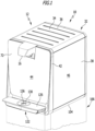
- a beverage preparation device 10 in the form of a water dispenser 12 is shown schematically as an example. It is designed for the treatment of drinking water and is preferably designed to be pipe-connected.
- the water dispenser 12 comprises a liquid inlet 14, optionally several liquid inlets can also be provided, and a beverage outlet 16, from which treated drinking water 18 can be filled into a container 20, for example a glass.
- the beverage outlet 16 is part of a beverage dispensing device 22 which can optionally include a beverage outlet valve 24 .
- the beverage outlet valve 24 is designed in particular to control the delivery of a beverage and can be designed to be controlled and/or regulated electrically or pneumatically.
- an electromagnetic drive 26 for opening and closing the beverage outlet valve 24 can be provided.
- the liquid inlet 14 and the beverage outlet 16 are fluidically connected to one another via a liquid line network 28 . It comprises a plurality of connecting lines 30 which fluidly connect individual components of the beverage preparation device 10 through which water flows.
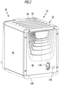
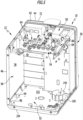
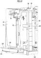
- the water dispenser 10 further includes a housing 32 having a removable housing top cover 34 forming one of a plurality of housing sections 36 .
- the housing parts 36 are, in particular, self-supporting plastic components 38 made of plastic, for example by injection molding.
- the cover 44 can be designed, for example, in the form of a glass pane.
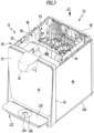
- a component or valve carrier 54 forms part of the housing 32. It is self-supporting and connected on the one hand to the intermediate housing part 50 and on the other hand to the housing rear wall 40, for example screwed and/or latched.
- the housing base 50, the housing rear wall 40, the housing intermediate part 50 and the valve carrier 54 form a self-supporting frame 56 of the water dispenser 12, on which its further housing parts 36 and the components required for its operation are arranged.
- the right housing wall 46 and the left housing wall 48 can be removed, as can the housing top cover 34, without this having a significant effect on the stability of the water dispenser 12.
- a housing interior 58 defined by the housing 32 can thus be easily opened in order to be able to access components arranged therein essentially freely.
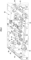
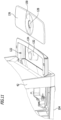
- valve carrier 54 is positioned in the housing interior 58 in such a way that control and/or regulating valves 64 can be inserted directly from above into valve receptacles 60 correspondingly provided on the valve carrier 54 .
- the control and/or regulating valves 64 are preferably in the form of electrically controllable valves and include a valve drive 66.
- an electromagnetic valve drive 66 can be provided for opening and closing the control and/or regulating valves 64.
- the control and/or regulating valves 64 each have a valve inlet 68 and a valve outlet 70 .
- the control and/or regulating valves 64 are arranged on the valve carrier 54 in the valve receptacles 60 in such a way that their valve inlets 68 and their valve outlets 80 point in the direction of a front side 72 or a rear side 74 of the housing.
- the valve drives 66 are arranged between the valve inlets 68 and the valve outlets 70 on the one hand and the housing cover 34 on the other hand.
- control and/or regulating valves 64 or a pressure switch 76 in a pressure switch receptacle 62 that is inserted into a pressure switch receptacle 62 This arrangement simplifies the assembly of the control and/or regulating valves 64 and also their maintenance and, if necessary, repair. Preferably, all components that require intensive maintenance can be arranged so that they are easily accessible for a user.
- an electrical connection line 78 to a preferably central control and/or regulation device 80 is shown schematically for a pressure switch 76 and a control and/or regulating valve 64, from which at least some, preferably all, of the electrically controllable and/or regulated Components of the water dispenser 12 can be controlled.
- control and/or regulating device 80 can be operatively connected to an actuating element 82 via a further connecting line 78, so that an operator, as a result of actuating the actuating element 82, for example embodied in the form of a push button or pressure switch, and valve closing processes and optionally also pump cycles by the control and/or regulating device 80 and/or in particular the drive 26 of the beverage outlet valve 24 is actuated by it in such a way that drinking water 18 flows out of the beverage outlet 16 into the container 20.
- Valve carrier 54 also has a cable routing device 84 comprising two cable ducts 86, which are formed on the end face of valve carrier 54 and are aligned transversely to a longitudinal direction defined by this , ie parallel to the cable ducts 86.
- the valve carrier 54 and the cable ducts 86 together form a one-piece component.
- fastening elements 88 are arranged on the valve receptacles 60 and the pressure switch receptacles 62, preferably in the form of latching elements 90 protruding essentially in the direction of the housing cover 34 or educated. They make it possible to clip the control and/or regulating valves 64 into the valve receptacles 60 or the pressure switch 76 into a pressure switch receptacle 62 from above. Further fastening elements for fixing the components described on the valve carrier 54 are then not absolutely necessary.
- Electrical connecting lines 78 of the beverage preparation device 10 can be routed in the cable ducts 86 in a particularly space-saving and nevertheless clear manner and routed to the electrically controllable and/or adjustable components arranged on the valve carrier 54 .
- cable holding elements can also be arranged or formed on the housing parts 36 , for example in the form of cable duct-like recesses or cable clips formed integrally with the respective housing part 36 .
- these make it possible to lay connecting lines and/or cables that can be laid to form the liquid line network 28 or for the electrically conductive connection of electrically actuated or controllable components of the water dispenser 12 .
- the cable holding elements can optionally also be in the form of tabs or hooks. Projections 94 and 98 pointing into the housing interior 58 are used to connect hooks, rails and/or guides for holding the housing walls 46, 48.
- the projections 94, 98 are preferably hollow so that they are not visible on an external visible side of the housing base 52 .
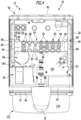
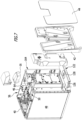
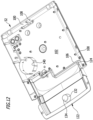
- the housing base 52 is at least partially trough-shaped and includes a liquid collection container 100. This is formed integrally with the housing base 52.
- a case bottom surface 102 of the case bottom 52 faces toward the case top cover 34 and is recessed toward the case cover 34 relative to a case bottom exterior 104 .
- the liquid collection container 100 at least partially surrounds the housing bottom surface 102 . As in figure 12 to recognize, the liquid collection container 100 surrounds the housing bottom surface 102 in a substantially U-shape. Both the liquid collection container 100 and the housing bottom surface 102 are delimited by a bulkhead 106 projecting in the direction of the housing cover 34 in the manner of a flange.
- the liquid collection container 100 has a liquid collection container outlet 108 . This is designed in the form of a bore, which is arranged below the housing rear wall 40 and can be closed with a plug, not shown in the figures.
- a detector 110 for determining a filling level of liquid 112 collected in the liquid collecting container 100 is provided.
- Detector 112 can include, in particular, a reed contact that can be actuated by means of a float, which is connected to control and/or regulating device 80 via an electrically conductive connecting line 78, for example in order to deactivate water dispenser 12 or, in particular, an electromagnetically actuatable inlet valve 114, which is connected to the liquid inlet 14 downstream, to prevent the liquid collection container 100 from overflowing.
- the left and/or right side wall of the housing are designed in such a way that they can be removed without dismantling other parts of the housing 32 .
- a passage 116 in the form of a circular opening is preferably arranged on the housing rear wall 40 and is used for passage of the liquid inlet 14 .
- an opening 118 for a mains connection device 120 for electrically conductive connection to a mains supply can also be provided on the housing rear wall 40 .
- the mains connection device 120 can be designed in particular in the form of a mains plug connection socket, which can be connected to a first end of a standardized mains connection cable, the other end of which can be inserted into a socket, for example a domestic socket.
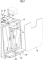
- the water dispenser 12 also includes a drip tray 122 which is designed like a drawer and can be pushed partially into the housing 52 . For emptying, the drip tray 122 can be pulled out completely from a recess 124 provided for this purpose, which is formed in the housing floor 52 .
- the drip tray 122 is arranged in the direction of gravity below the beverage outlet 16 and below the cover 44.
- a drip tray cover 126 is used to close the part of the drip tray 122 protruding from the housing 52.
- the drip tray cover 126 has a circular drip tray cover opening 128, which is formed in the center of an annular drainage surface 130 that slopes in the direction of the drip tray cover opening 128.
- a drip body 132 pointing in the direction of the drip tray cover 126 is formed in one piece with the drip tray 122 . It essentially has the shape of a truncated cone and ends in a trickling filter surface 134 which is slightly convexly curved in the direction of the beverage outlet 16 .
- the dripping body 132 is arranged and designed in such a way that an annular opening 136 is formed between the dripping body surface 134 and the drip tray cover opening 128 . If liquid 18 drips onto the drainage surface 130, it is guided through the opening 136 into the drip tray 122. If a drop of liquid hits the dripping body surface 134, then it is deflected in a defined manner and also guided through the opening 136 into the drip tray 122.
- the liquid inlet 14 is designed in particular in the form of a water inlet for connection to a tap 138 of an external drinking water network 140 . In particular, this makes it possible to use the water dispenser 12 to continuously prepare drinking water 18 and make it available.
- the water dispenser 12 can optionally include a filter device 142 with which water flowing through the liquid inlet 14 is filtered out of the drinking water network 140 .
- the filter device 142 can in particular comprise at least one water filter 144. This can be designed in particular in the form of a water filter cartridge that can be replaced at regular intervals.
- the water dispenser 12 can optionally include a sterilization device 146 for sterilizing the water flowing through the liquid line network 28 .
- the sterilization device 146 can include a UV light source 148 for irradiating the liquid flowing through the liquid line network 28 with UV radiation.
- a thermal hygienization device can also be provided, with which a thermal hygienization of the water dispenser can be carried out.
- hot water is circulated for a specific time in the water dispenser, in particular in the liquid line network 28, and then flushed out.
- a chemical cleaning of the water dispenser in which a cleaning solution is introduced into the liquid line network 28 and rinsed out again after a certain dwell time in the water dispenser.
- the water dispenser 12 can optionally also include a carbon dioxide mixing device 150 with a carbon dioxide outlet 152 for charging the liquid flowing in the liquid line network 28 with carbon dioxide.
- the carbon dioxide outlet 152 is in fluid connection with the liquid line network 28 .
- the carbon dioxide mixing device 150 can comprise an outlet valve 154 for controlling and/or regulating a carbon dioxide flow through the carbon dioxide outlet 152 .
- outlet valve 154 can be controlled by control and/or regulation device 80, for example depending on the actuation of an actuating element 156 provided for this purpose, which is operatively connected to control and/or regulation device 80.
- the carbon dioxide can also be admixed in a different way, namely purely mechanically via the secondary pressure set on a pressure reducer and the water pressure present on a mixer.
- a carbon dioxide reservoir 158 can be arranged either externally, possibly in a vertical column 166, or internally, for example on a special receptacle with an integrated pressure reducer.
- the special receptacle with the pressure reducer can be installed behind the door formed by the front wall 42 in the intermediate housing part 50 or can be screwed on at the top.
- the carbon dioxide reservoir 158 can in particular be designed in the form of a carbon dioxide compressed gas cylinder which is in fluid communication with the carbon dioxide mixing device 150 via a pressure line 162 .
- the beverage preparation device 10 can also include a heating device, not shown in the figures, for heating water and/or a beverage prepared ready for dispensing, for example in the form of a boiler, which is inserted into a receptacle 160 provided for it on the housing base 52.
- a heating device not shown in the figures, for heating water and/or a beverage prepared ready for dispensing, for example in the form of a boiler, which is inserted into a receptacle 160 provided for it on the housing base 52.
- the intermediate housing part 50 is preferably embodied in the form of a component carrier 164, on which one or more components of the water dispenser 12, in particular the disinfection device 146, the carbon dioxide mixing device 150 and/or the central control and/or regulation device 80, can be arranged.
- the water dispenser 12 can be used in particular as a tabletop device in the figure 1 illustrated designs are set up or arranged on the pedestal 166, which can be used in particular to accommodate a supply of carbon dioxide bottles or beverage cups.
Description
Die vorliegende Erfindung betrifft eine Getränkezubereitungsvorrichtung mit mindestens einem Flüssigkeitseinlass, einer Getränkeabgabeeinrichtung umfassend mindestens einen Getränkeauslass, einen den mindestens einen Flüssigkeitseinlass und den mindestens einen Getränkeauslass fluidisch verbindenden Flüssigkeitsleitungsnetz und einem Gehäuse, wobei das Gehäuse eine obere Gehäuseabdeckung umfasst, wobei unterhalb der oberen Gehäuseabdeckung ein Ventilträger angeordnet ist, an dem mindestens zwei Steuer- und/oder Regelungsventile der Getränkezubereitungsvorrichtung angeordnet und nach Entfernen der oberen Gehäuseabdeckung frei zugänglich sind, und wobei ein Gehäuseboden im Wesentlichen wannenförmig ausgebildet ist und einen integral ausgebildeten Flüssigkeitssammelbehälter umfasst.The present invention relates to a beverage preparation device with at least one liquid inlet, a beverage dispensing device comprising at least one beverage outlet, a liquid line network fluidically connecting the at least one liquid inlet and the at least one beverage outlet, and a housing, the housing comprising an upper housing cover, with a valve carrier underneath the upper housing cover is arranged on which at least two control and/or regulating valves of the beverage preparation device are arranged and are freely accessible after removing the upper housing cover, and wherein a housing base is essentially trough-shaped and includes an integrally formed liquid collection container.
Getränkezubereitungsvorrichtungen der eingangs beschriebenen Art sind beispielsweise in Form von sogenannten Wasserspendern bekannt, die zur Abgabe insbesondere von aufbereitetem Trinkwasser dienen. Gehäuse derartiger Wasserspender sind üblicherweise aus Blechen gefertigt und weisen auch metallische Rahmenteile auf. Ferner sind einzelne Komponenten, beispielsweise Magnetventile zur Steuerung eines Flüssigkeitsstroms durch das Flüssigkeitsleitungsnetz, im Wesentlichen beliebig verteilt im Gehäuse angeordnet und mit dem Flüssigkeitsleitungsnetz verbunden. Daraus ergeben sich insbesondere bei regelmäßig durchzuführenden Wartungen sowie fallweisen Reparaturen der Getränkezubereitungsvorrichtungen Probleme bei deren Durchführung, welche zu zeitaufwendigen und damit kostenintensiven Eingriffen führen, nicht zuletzt deshalb, weil einzelne Komponenten der Getränkezubereitungsvorrichtungen schlecht zugänglich sind.Beverage preparation devices of the type described above are known, for example, in the form of so-called water dispensers, which are used in particular to dispense treated drinking water. Housings of such water dispensers are usually made of sheet metal and also have metallic frame parts. Furthermore, individual components, for example solenoid valves for controlling a liquid flow through the liquid line network, are distributed in the housing essentially in any way and are connected to the liquid line network. This results in problems when carrying out regular maintenance and occasional repairs of the beverage preparation devices, which lead to time-consuming and therefore costly interventions, not least because individual components of the beverage preparation devices are difficult to access.
Aus der
Es ist daher eine Aufgabe der vorliegenden Erfindung, Getränkezubereitungsvorrichtungen der eingangs beschriebenen Art so zu verbessern, dass insbesondere deren Montage und Wartung vereinfacht wird.It is therefore an object of the present invention to improve beverage preparation devices of the type described at the outset in such a way that in particular their assembly and maintenance is simplified.
Diese Aufgabe wird bei einer Getränkezubereitungsvorrichtung der eingangs beschriebenen Art erfindungsgemäß gelöst durch eine Getränkezubereitungsvorrichtung gemäß Anspruch 1.In the case of a beverage preparation device of the type described at the outset, this object is achieved according to the invention by a beverage preparation device according to claim 1.
Die erfindungsgemäß vorgeschlagene Weiterbildung ermöglicht es insbesondere, auf besonders wartungsintensive Komponenten der Getränkezubereitungsvorrichtung einfach und schnell zugreifen zu können, beispielsweise zu Wartungs- oder Reparaturzwecken. So können insbesondere die mindestens zwei Steuer- und/oder Regelungsventile übersichtlich und leicht zugänglich im Gehäuse angeordnet werden. Es muss lediglich die obere Gehäuseabdeckung entfernt werden, um direkt, ohne an anderen Komponenten vorbei, auf die Steuer- und/oder Regelungsventile zugreifen zu können. Eine solche Anordnung ermöglicht zudem eine einfache Montage sowie eine übersichtliche Anordnung des Flüssigkeitsleitungsnetzes sowie etwaiger elektrisch leitfähiger Verbindungsleitungen innerhalb des Gehäuses. Gemäß der Erfindung ist vorgesehen, dass ein Gehäuseboden im Wesentlichen wannenförmig ausgebildet ist und einen integral ausgebildeten Flüssigkeitssammelbehälter umfasst. Wannenförmig bedeutet insbesondere nicht, dass eine im Wesentlichen komplette Fläche des Gehäusebodens die Wanne bilden muss. Diese kann auch nur einen Teil der vom Gehäuseboden definierten Fläche beanspruchen. Der Flüssigkeitssammelbehälter kann insbesondere dem Zweck dienen, bei Leckagen ausgetretene Flüssigkeit zu sammeln, so dass diese nicht aus dem Gehäuse herauslaufen und beispielsweise einen Boden oder ein Möbelstück, auf dem die Getränkezubereitungsvorrichtung aufgestellt ist, in unerwünschter Weise mit einer durch das Flüssigkeitsleitungsnetz strömenden Flüssigkeit beaufschlagen und insbesondere verschmutzen kann. Vorteilhaft ist es, dass der Gehäuseboden eine von einer von der Gehäuseabdeckung weg weisenden Gehäusebodenaußenseite in Richtung auf die Gehäuseabdeckung zurückgesetzte Gehäusebodenfläche aufweist und dass der Flüssigkeitssammelbehälter die Gehäusebodenfläche mindestens teilweise umgibt. Insbesondere kann der Flüssigkeitssammelbehälter in Form einer teilweise oder vollständig umlaufenden Rinne ausgebildet sein, welche ein Volumen definiert, um nicht nur Flüssigkeit im Falle einer Leckage aufzunehmen, sondern beispielsweise auch kondensierte Flüssigkeit, die sich im Inneren des Gehäuses beispielsweise niederschlagen können, wenn die Getränkezubereitungsvorrichtung optional eine Kühleinrichtung umfasst. Die Kühleinrichtung kann beispielsweise dazu dienen, eine durch den Getränkeauslass strömende Flüssigkeit beziehungsweise ein Getränk zu kühlen, und zwar vor oder während des Durchströmens des Getränkeauslasses. Insbesondere kann dies in Verbindung mit einem Karbonator vorteilhaft sein, um so die Flüssigkeit effizient mit Kohlenstoffdioxid zu versetzen. Der in der beschriebenen Weise ausgebildete Gehäuseboden mit der zurückgesetzten Gehäusebodenfläche ermöglicht es insbesondere auch, Komponenten der Getränkezubereitungsvorrichtung derart zu positionieren, dass keine Gefahr besteht, dass im Falle des Austretens von Flüssigkeit aus dem Flüssigkeitsleitungsnetz diese Komponenten mit Flüssigkeit dauerhaft geflutet werden können. Sie sind damit höher angeordnet als der Flüssigkeitssammelbehälter und sind somit optimal geschützt anordenbar.The development proposed according to the invention makes it possible, in particular, to be able to access particularly maintenance-intensive components of the beverage preparation device easily and quickly, for example for maintenance or repair purposes. In particular, the at least two control and/or regulating valves can be arranged in the housing in a clear and easily accessible manner. Only the top housing cover has to be removed in order to be able to access the control and/or regulation valves directly without bypassing other components. Such an arrangement also enables simple assembly and a clear arrangement of the liquid line network and any electrically conductive connecting lines within the housing. According to the invention, it is provided that a housing base is essentially trough-shaped and includes an integrally designed liquid collection container. In particular, trough-shaped does not mean that an essentially complete area of the housing base has to form the trough. This can also only take up part of the area defined by the bottom of the housing. The liquid collection container can in particular serve the purpose of collecting liquid that has escaped in the event of leaks, so that it does not run out of the housing and, for example, impinge on a floor or a piece of furniture on which the beverage preparation device is set up with a liquid flowing through the liquid line network in an undesired manner and in particular can pollute. It is advantageous that the housing base has a housing base surface set back from a housing base exterior pointing away from the housing cover in the direction of the housing cover and that the liquid collecting container at least partially surrounds the housing base surface. In particular, the liquid collection container can be designed in the form of a partially or completely encircling channel, which defines a volume in order to receive not only liquid in the event of a leak, but also, for example, condensed liquid that can condense inside the housing, for example, if the beverage preparation device is optional includes a cooling device. The cooling device can be used, for example, to cool a liquid or a beverage flowing through the beverage outlet, specifically before or during the flow through the beverage outlet. In particular, this can be advantageous in connection with a carbonator in order to efficiently add carbon dioxide to the liquid. The housing base designed in the manner described with the recessed housing base surface also makes it possible in particular to position components of the beverage preparation device in such a way that there is no risk that, in the event of liquid escaping from the liquid line network, this Components can be permanently flooded with liquid. They are therefore arranged higher than the liquid collection container and can therefore be arranged with optimal protection.
Gemäß einer weiteren bevorzugten Ausführungsform der Erfindung kann vorgesehen sein, dass das Gehäuse in Form eines selbsttragenden Gehäuses ausgebildet ist, dass das Gehäuse eine Mehrzahl aus einem Kunststoff gefertigter Gehäuseteile umfasst und dass mindestens ein Teil der Gehäuseteile Komponentenhalteeinrichtungen aufweisen zum Halten weiterer, die Getränkezubereitungsvorrichtung ausbildender Komponenten. Insbesondere hat die vorgeschlagene Weiterbildung den Vorteil, dass das Gewicht der Getränkezubereitungsvorrichtung durch Ausbildung des Gehäuses mit teilweise oder vollständig aus einem Kunststoff gefertigter Gehäuseteile im Vergleich zum am Markt verfügbarer Getränkezubereitungsvorrichtungen deutlich reduziert werden kann. Zudem ermöglichen es die Komponentenhalteeinrichtungen mindestens an einem Teil der Gehäuseteile, auf einfache Weise weitere Komponenten der Getränkezubereitungsvorrichtung zu montieren. Beispielsweise können Leitungs- oder Kabelhalterungen an einem oder mehreren Gehäuseteilen vorgesehen sein, um daran Kabel anzubringen, beispielsweise festzuclipsen. Es können aber auch Aufnahmen sein, in die beispielsweise Ventile, Schalter oder elektrisch betriebene Einheiten der Getränkezubereitungsvorrichtung eingesetzt und mit oder ohne zusätzliche Befestigungselemente montiert werden können.According to a further preferred embodiment of the invention, it can be provided that the housing is designed in the form of a self-supporting housing, that the housing comprises a plurality of housing parts made of a plastic and that at least some of the housing parts have component holding devices for holding further components forming the beverage preparation device . In particular, the proposed development has the advantage that the weight of the beverage preparation device can be significantly reduced by designing the housing with housing parts made partially or entirely of plastic compared to beverage preparation devices available on the market. In addition, the component holding devices make it possible to easily mount further components of the beverage preparation device on at least some of the housing parts. For example, line or cable holders can be provided on one or more housing parts in order to attach cables to them, for example by clipping them in place. However, they can also be receptacles into which, for example, valves, switches or electrically operated units of the beverage preparation device can be inserted and mounted with or without additional fastening elements.
Vorteilhafterweise kann auf einen separaten Rahmen des Gehäuses insbesondere dadurch verzichtet werden, wenn das Gehäuse mindestens teilweise aus selbsttragenden Kunststoffbauteilen ausgebildet ist. Beispielsweise kann so die obere Abdeckung und/oder eine Seitenwand des Gehäuses nicht nur die Funktion aufweisen, das Gehäuse zu verschließen, sondern auch mindestens einen Teil der darin enthaltenen Komponenten, die am jeweils selbsttragend ausgebildeten Kunststoffbauteil angeordnet sind, zu tragen oder zu halten.Advantageously, a separate frame of the housing can be dispensed with in particular if the housing is at least partially formed from self-supporting plastic components. For example, the top cover and/or a side wall of the housing can not only have the function of closing the housing, but also of carrying or holding at least some of the components contained therein, which are arranged on the respective self-supporting plastic component.
Vorzugsweise umfassen die Gehäuseteile insbesondere den Ventilträger, die obere Gehäuseabdeckung, eine Gehäuserückwand, eine Gehäusefrontwand, eine rechte und eine linke Gehäuseseitenwand, ein zwischen der Gehäusefrontwand und der Gehäuserückwand angeordnetes Gehäusezwischenteil und einen Gehäuseboden. Das Gehäusezwischenteil ist nicht zwingend erforderlich. Zudem können ein oder mehrere der genannten Gehäuseteile auch einstückig miteinander ausgebildet sein. Insbesondere ist es möglich, beispielsweise die genannten Teile aus einem Kunststoff und zudem in einer selbsttragenden Weise auszubilden, so dass keine zusätzlichen, der Getränkezubereitungsvorrichtung Stabilität verleihenden Rahmenbauteile erforderlich sind.The housing parts preferably include in particular the valve carrier, the upper housing cover, a housing rear wall, a housing front wall, a right and a left housing side wall, an intermediate housing part arranged between the housing front wall and the housing rear wall, and a housing base. The intermediate housing part is not absolutely necessary. In addition, one or more of the housing parts mentioned can also be formed in one piece with one another. In particular, it is possible, for example, to form the parts mentioned from a plastic material and also in a self-supporting manner, so that no additional frame components that impart stability to the beverage preparation device are required.
Vorteilhaft ist es, wenn mindestens an einem Teil der Gehäuseteile Kabelhalteelemente zum Festlegen von Verbindungsleitungen und/oder Kabeln angeordnet oder ausgebildet sind. Insbesondere können die Kabelhalteelemente integral mit einem oder mehreren Gehäuseteilen ausgebildet sein. Diese Ausgestaltung erleichtert insbesondere die Montage von Verbindungsleitungen und/oder Kabeln am Gehäuse, da weder Schrauben noch Klammern oder Haken oder andere Elemente erforderlich sind, um die Verbindungsleitungen und/oder Kabel am Gehäuse festzulegen.It is advantageous if cable holding elements for fixing connecting lines and/or cables are arranged or formed on at least some of the housing parts. In particular, the cable holding elements can be formed integrally with one or more housing parts. In particular, this configuration facilitates the assembly of connecting lines and/or cables on the housing, since neither screws nor clamps or hooks or other elements are required to fix the connecting lines and/or cables to the housing.
Günstigerweise sind die Kabelhalteelemente in Form von Laschen oder Haken ausgebildet. Dies ermöglicht es insbesondere, Verbindungsleitungen und/oder Kabel beispielsweise durch Laschen hindurchzuführen oder in Haken an einem oder mehreren Gehäuseteilen einzuhängen, so dass sie sich einfach und schnell bei der Montage anordnen lassen. Zudem kann so auch die Übersichtlichkeit des Aufbaus der Getränkezubereitungsvorrichtung verbessert werden.The cable holding elements are favorably designed in the form of lugs or hooks. This makes it possible, in particular, to feed connecting lines and/or cables, for example, through lugs or to hang them in hooks on one or more housing parts, so that they can be arranged easily and quickly during assembly. In addition, the clarity of the structure of the beverage preparation device can also be improved in this way.
Um einen Flüssigkeitsstrom durch das Flüssigkeitsleitungsnetz insbesondere automatisch steuern zu können, ist es günstig, wenn die mindestens zwei Steuer- und/oder Regelungsventile in Form elektrisch steuerbarer Ventile ausgebildet sind.In order to be able to control a liquid flow through the liquid line network, in particular automatically, it is favorable if the at least two control and/or regulating valves are designed in the form of electrically controllable valves.
Vorteilhaft ist es, wenn die mindestens zwei Steuer- und/oder Regelungsventile einen Ventilantrieb zum Öffnen und/oder Schließen derselben aufweisen. Beispielsweise kann der Ventilantrieb in Form eines elektromagnetischen oder pneumatischen Ventilantriebs ausgebildet sein. So kann durch einen elektrischen oder pneumatischen Steuerstrom eine Stellung der Steuer- und/oder Regelungsventile geändert werden, um beispielsweise einen Flüssigkeitsstrom durch das Flüssigkeitsleitungsnetz zuzulassen oder zu unterbinden. Vorzugsweise weisen die mindestens zwei Steuer- und/oder Regelungsventile einen Ventileinlass und einen Ventilauslass auf, welche in voneinander entgegengesetzte Richtungen weisen. Insbesondere können Längsachsen des Ventileinlasses und des Ventilauslasses parallel zueinander verlaufen oder sogar zusammen fallen. Bei einer Anordnung der mindestens zwei Steuer- und/oder Regelungsventile am Ventilträger ist es somit möglich, die Steuer- und/oder Regelungsventile so anzuordnen, dass sowohl der Ventileinlass als auch der Ventilauslass nach Abnehmen der oberen Gehäuseabdeckung frei zugänglich sind.It is advantageous if the at least two control and/or regulating valves have a valve drive for opening and/or closing them. For example, the valve drive can be in the form of an electromagnetic or pneumatic valve drive. A position of the control and/or regulating valves can be changed by an electrical or pneumatic control current, for example in order to permit or prevent a liquid flow through the liquid line network. The at least two control and/or regulating valves preferably have a valve inlet and a valve outlet, which point in opposite directions from one another. In particular, longitudinal axes of the valve inlet and the valve outlet can run parallel to one another or even coincide. With an arrangement of at least two control and/or regulation valves on the valve carrier, it is thus possible to arrange the control and/or regulation valves in such a way that both the valve inlet and the valve outlet are freely accessible after removing the upper housing cover.
Gemäß einer weiteren bevorzugten Ausführungsform der Erfindung kann vorgesehen sein, dass die mindestens zwei Steuer- und/oder Regelungsventile am Ventilträger derart angeordnet sind, dass ihre Ventileinlässe und ihre Ventilauslässe in Richtung auf eine Gehäuserückseite des Gehäuses oder in Richtung auf eine Gehäusevorderseite des Gehäuses weisen. Insbesondere können alle Steuer- und/oder Regelungsventile in der beschriebenen Weise angeordnet werden. Damit können Verbindungsleitungen des Flüssigkeitsleitungsnetzes in übersichtlicher Weise und in gleicher Ausrichtung mit den mindestens zwei Steuer- und/oder Regelungsventilen verbunden werden.According to a further preferred embodiment of the invention, it can be provided that the at least two control and/or regulating valves are arranged on the valve carrier in such a way that their valve inlets and valve outlets point in the direction of a rear side of the housing or in the direction of a front side of the housing. In particular, all the control and/or regulating valves can be arranged in the manner described. This allows connecting lines of the liquid line network be connected to the at least two control and/or regulating valves in a clear manner and in the same orientation.
Ferner ist es vorteilhaft, wenn das mindestens eine Steuer- und/oder Regelungsventil am Ventilträger derart angeordnet ist, dass der Ventilantrieb zwischen dem Ventileinlass und dem Ventilauslass einerseits und der Gehäuseabdeckung andererseits angeordnet ist. Dies ist insbesondere so zu verstehen, dass der Ventilantrieb direkt unterhalb der oberen Gehäuseabdeckung angeordnet sein kann, also frei zugänglich ist, wenn diese vom Gehäuse entfernt ist. Der Ventilantrieb sitzt dann oberhalb, also der oberen Gehäuseabdeckung zugewandt, des Ventileinlasses und des Ventilauslasses.It is also advantageous if the at least one control and/or regulating valve is arranged on the valve carrier in such a way that the valve drive is arranged between the valve inlet and the valve outlet on the one hand and the housing cover on the other. This is to be understood in particular in such a way that the valve drive can be arranged directly below the upper housing cover, ie is freely accessible when this is removed from the housing. The valve drive then sits above, ie facing the upper housing cover, the valve inlet and the valve outlet.
Um insbesondere einen Flüssigkeitsstrom durch das Flüssigkeitsleitungsnetz druckabhängig zu steuern und/oder zu regeln, ist es vorteilhaft, wenn die Getränkezubereitungsvorrichtung einen Druckschalter umfasst. Insbesondere kann mindestens ein mit dem Flüssigkeitsleitungsnetz und/oder einem CO2-Leitungsnetz zusammenwirkender oder verbundener Druckschalter am Ventilträger angeordnet sein. Aufgrund der besonderen Anordnung des Ventilträgers ist dann auch der Druckschalter leicht zugänglich, beispielsweise um Messungen zu Testzwecken an diesem vorzunehmen. Insbesondere kann es sich bei dem Druckschalter um einen CO2-Druckschalter handeln, welcher beispielsweise ein Steuersignal an eine Steuer- und/oder Regelungseinrichtung der Getränkezubereitungsvorrichtung senden kann, wenn ein mit dem Flüssigkeitsleitungsnetz zusammenwirkender oder mit diesem über eine CO2-Versorgungsleitung des CO2-Leitungsnetzes verbundener CO2-Speicher, insbesondere eine CO2-Flasche, leer ist.In order in particular to control and/or regulate a liquid flow through the liquid line network as a function of pressure, it is advantageous if the beverage preparation device comprises a pressure switch. In particular, at least one pressure switch which interacts with or is connected to the liquid line network and/or a CO 2 line network can be arranged on the valve carrier. Due to the special arrangement of the valve carrier, the pressure switch is then also easily accessible, for example in order to carry out measurements on it for test purposes. In particular, the pressure switch can be a CO 2 pressure switch, which can , for example, send a control signal to a control and/or regulating device of the beverage preparation device if a CO 2 -Line network associated CO 2 storage, especially a CO 2 bottle, is empty.
Um Kabel oder Verbindungsleitungen einfach zu montieren und übersichtlich anzuordnen, kann die Getränkezubereitungsvorrichtung mindestens eine Kabelführungseinrichtung aufweisen. Insbesondere kann diese in Form eines Kabelkanals oder mehrerer ähnlich oder identisch ausgebildeter Kabelhalterungen ausgebildet sein. Insbesondere ist es vorteilhaft, wenn der Ventilträger eine Kabelführungseinrichtung aufweist und wenn elektrische Verbindungsleitungen der Getränkezubereitungsvorrichtung zu insbesondere am Ventilträger angeordneten, elektrisch angesteuerten Komponenten an oder in der Kabelführungseinrichtung verlegt sind. Durch diese Ausgestaltung können insbesondere elektrische Verbindungsleitungen und optional auch Verbindungsleitungen des Flüssigkeitsleitungsnetzes in definierter und übersichtlicher Weise im Gehäuse verlegt werden.In order to mount cables or connecting lines easily and arrange them clearly, the beverage preparation device can have at least one cable routing device. In particular, this can be designed in the form of a cable duct or several similarly or identically designed cable holders. In particular, it is advantageous if the valve carrier has a cable routing device and if electrical connecting lines of the beverage preparation device to electrically controlled components arranged in particular on the valve carrier are routed on or in the cable routing device. With this configuration, in particular electrical connecting lines and optionally also connecting lines of the liquid line network can be laid in the housing in a defined and clear manner.
Vorteilhaft ist es, wenn der Ventilträger eine Längsachse definiert, welche sich quer zu einer Verbindungslinie zwischen einer Gehäusevorderseite und ein Gehäuserückseite des Gehäuses erstreckt. Alternativ kann der Ventilträger auch eine Längsachse definieren, welche sich parallel oder im Wesentlichen parallel zu einer Verbindungslinie zwischen einer Gehäusevorderseite oder einer Gehäuserückseite des Gehäuses erstreckt. In jedem Fall ermöglicht ein solcher Ventilträger, an ihm Komponenten in gleicher Art und definierter Weise anzuordnen und zu befestigen.It is advantageous if the valve carrier defines a longitudinal axis which extends transversely to a connecting line between a front side of the housing and a rear side of the housing. Alternatively, the valve carrier can also define a longitudinal axis which extends parallel or essentially parallel to a connecting line between a front side or a rear side of the housing. In any case, such a valve carrier makes it possible to arrange and attach components to it in the same way and in a defined manner.
Um den Flüssigkeitssammelbehälter auf einfache Weise leeren zu können, ist es vorteilhaft, wenn dieser einen Flüssigkeitssammelbehälterauslass zum Entleeren darin gesammelter Flüssigkeit aufweist. Insbesondere kann der Flüssigkeitssammelbehälterauslass in Form einer Durchbrechung ausgebildet sein, welche eine Achse definierte, die parallel oder im Wesentlichen parallel zu einer Verbindungslinie vom Gehäuseboden zur oberen Gehäuseabdeckung verläuft. Beispielsweise kann so der Flüssigkeitssammelbehälter über einen mit dem Flüssigkeitssammelbehälterauslass verbundenen Schlauch oder einfach durch Darunterhalten eines weiteren Behälters entleert werden.In order to be able to empty the liquid collection container in a simple manner, it is advantageous if it has a liquid collection container outlet for emptying liquid collected therein. In particular, the liquid reservoir outlet may be in the form of an aperture defining an axis parallel or substantially parallel to a line connecting the housing bottom to the housing top cover. For example, the liquid collection container can be emptied via a hose connected to the liquid collection container outlet or simply by holding another container underneath.
Um zu vermeiden, dass der Flüssigkeitssammelbehälter überlaufen kann, ist es günstig, wenn die Getränkezubereitungsvorrichtung einen Detektor zum Bestimmen eines Füllstands von im Flüssigkeitssammelbehälter gesammelter Flüssigkeit umfasst. Insbesondere kann ein vom Detektor erzeugtes Steuersignal genutzt werden, gegebenenfalls die Getränkezubereitungsvorrichtung vorsorglich zu deaktivieren, um Schäden an derselben oder das unerwünschte Austreten von Flüssigkeit im Falle des Überlaufens des Flüssigkeitssammelbehälters zu unterbinden. Beispielsweise kann das Steuersignal genutzt werden, um ein Einlassventil am mindestens einen Flüssigkeitseinlass automatisch zu verschließen.In order to prevent the liquid collection container from being able to overflow, it is favorable if the beverage preparation device comprises a detector for determining the fill level of liquid collected in the liquid collection container. In particular, a control signal generated by the detector can be used to deactivate the beverage preparation device as a precautionary measure, if necessary, in order to prevent damage to the same or the undesired escape of liquid in the event of the liquid collecting container overflowing. For example, the control signal can be used to automatically close an inlet valve on the at least one liquid inlet.
Der Ventilträger ist an einer Gehäuserückwand einerseits und/oder an einem selbsttragenden, am Gehäuseboden gehaltenen Gehäusezwischenteil oder einer Gehäusefrontwand andererseits festgelegt. Eine solche Ausgestaltung ermöglicht es beispielsweise, das Gehäuse durch Gehäuseseitenwände zu verschließen, die ohne einen Eingriff auf die Stabilität des Gehäuses entfernt werden können, um auf das Innere des Gehäuses und die darin angeordneten Komponenten zu Wartungs-, Reparatur- und/oder Reinigungszwecken zugreifen zu können. Zudem bildet der Ventilträger bei entsprechender Ausgestaltung und einer Anordnung in der beschriebenen Weise optional auch eine Verstärkung beziehungsweise Verstrebung des Gehäuses.The valve carrier is fixed to a housing rear wall on the one hand and/or to a self-supporting intermediate housing part held on the housing floor or to a housing front wall on the other hand. Such a configuration makes it possible, for example, to close the housing with housing side walls that can be removed without affecting the stability of the housing in order to access the interior of the housing and the components arranged therein for maintenance, repair and/or cleaning purposes can. In addition, with a corresponding configuration and an arrangement in the manner described, the valve carrier optionally also forms a reinforcement or strut of the housing.
Gemäß einer weiteren bevorzugten Ausführungsform der Erfindung kann vorgesehen sein, dass die linke und/oder die rechte Gehäuseseitenwand abnehmbar, ohne weitere Teile des Gehäuses zu demontieren, an den weiteren, das Gehäuse ausbildenden Teilen des Gehäuses angeordnet sind. Beispielsweise können die rechte und/oder die linke Gehäuseseitenwand verrastbar mit den restlichen Gehäuseteilen verbunden sein. Optional ist es auch möglich, die Gehäuseseitenwände zusätzlich mit Befestigungselementen wie Schrauben oder Klammern zu sichern.According to a further preferred embodiment of the invention, it can be provided that the left and/or the right housing side wall are arranged on the other parts of the housing that form the housing so that they can be removed without dismantling other parts of the housing. For example, the right and/or the left housing side wall can be connected to the remaining housing parts in a latchable manner. Optionally, it is also possible to additionally secure the housing side walls with fastening elements such as screws or clamps.
Vorzugsweise weist die Gehäuserückwand eine Durchführung für den Flüssigkeitseinlass und/oder eine Durchbrechung für eine Netzanschlusseinrichtung zum elektrisch leitfähigen Verbinden mit einem Stromnetz auf. Die Durchführung für den Flüssigkeitseinlass ermöglicht es insbesondere, die Getränkezubereitungsvorrichtung mit einem Wasserversorgungsnetz zu verbinden, beispielsweise an einen Wasserhahn anzuschließen. Zum Betrieb elektrischer Komponenten der Getränkezubereitungsvorrichtung ermöglicht es die Netzanschlusseinrichtung, die Getränkezubereitungsvorrichtung mit einem elektrischen Versorgungsnetz zu verbinden. Optional kann die Getränkezubereitungsvorrichtung auch derart ausgebildet, dass sie netzunabhängig betreibbar ist, beispielsweise mit einer im Gehäuse angeordneten Batterie. In diesem Fall kann dann auf eine Netzanschlusseinrichtung sowie eine Durchbrechung für diese verzichtet werden.The rear wall of the housing preferably has a passage for the liquid inlet and/or an opening for a mains connection device for electrically conductive connection to a power supply. The passage for the liquid inlet makes it possible in particular to connect the beverage preparation device to a water supply network, for example to a water tap. In order to operate electrical components of the beverage preparation device, the mains connection device makes it possible to connect the beverage preparation device to an electrical supply network. Optionally, the beverage preparation device can also be designed in such a way that it can be operated independently of the mains, for example with a battery arranged in the housing. In this case, a mains connection device and an opening for this can then be dispensed with.
Auf einfache Weise lässt sich die Getränkezubereitungsvorrichtung mit einem Stromnetz verbinden, wenn die Netzanschlusseinrichtung in Form einer Netzsteckeranschlussbuchse ausgebildet ist. Beispielsweise ist es so möglich, mit einem Standardnetzanschlusskabel die Getränkezubereitungsvorrichtung mit einem Stromnetz zu verbinden.The beverage preparation device can be connected to a mains power supply in a simple manner if the mains connection device is designed in the form of a mains plug connection socket. It is thus possible, for example, to connect the beverage preparation device to a mains power supply using a standard mains connection cable.
Um eine möglichst verlustfreie Entnahme eines Getränks zu ermöglichen sowie eine unerwünschte Beaufschlagung der Umgebung der Getränkezubereitungsvorrichtung bei Entnahme eines mit dieser zubereiteten Getränks aus dem Getränkeauslass möglichst zu vermeiden, ist es günstig, wenn die Getränkezubereitungsvorrichtung eine Tropfschale umfasst, welche unterhalb des Getränkeauslasses angeordnet ist. Mit der Tropfschale kann insbesondere aus dem Getränkeauslass austretende Flüssigkeit, die nicht in einen zu befüllenden Behälter gelangt, beispielsweise ein Glas oder einen Becher, aufgefangen werden.In order to enable a drink to be removed with as little loss as possible and to avoid as far as possible undesired impact on the surroundings of the beverage preparation device when a drink prepared with it is removed from the beverage outlet, it is favorable if the beverage preparation device comprises a drip tray which is arranged below the beverage outlet. With the drip tray, in particular, liquid escaping from the beverage outlet that does not get into a container to be filled, for example a glass or a mug, can be caught.
Um die Tropfschale auf einfache Weise entleeren zu können, ist es vorteilhaft, wenn diese schubladenartig mindestens teilweise in das Gehäuse einschiebbar und zum Entleeren vollständig aus diesem herausziehbar ist.In order to be able to empty the drip tray in a simple manner, it is advantageous if it can be pushed at least partially into the housing in the manner of a drawer and can be completely pulled out of it for emptying.
Um zu vermeiden, dass nicht in den zu befüllenden Behälter gelangende Flüssigkeit aus dem Getränkeauslass die Getränkezubereitungsvorrichtung oder eine Bedienperson bespritzt, ist es günstig, wenn die Tropfschale einen Tropfkörper mit einer in Richtung auf den Getränkeauslass hin weisenden, konvex gekrümmten Tropfkörperfläche aufweist. Durch diese besondere Form des Tropfkörpers wird auftreffende Flüssigkeit in gewünschter Weise abgelenkt und von der Tropfschale aufgefangen. Um das Eindringen von Verschmutzungen in die Tropfschale zu vermeiden, ist es vorteilhaft, wenn die Tropfschale eine Tropfschalenabdeckung umfasst, welche den aus dem Gehäuse herausragenden Teil der Tropfschale mindestens teilweise verschließt und eine Tropfschalenabdeckungsdurchbrechung aufweist. Vom Getränkeauslass heruntertropfende Flüssigkeit kann insbesondere durch die Tropfschalenabdeckungsdurchbrechung in die Tropfschale hinein gelangen.In order to prevent liquid from the beverage outlet that does not get into the container to be filled from splashing the beverage preparation device or an operator, it is advantageous if the drip tray has a trickling filter with a convexly curved trickling filter surface pointing in the direction of the beverage outlet. Due to this special shape of the trickling filter, any liquid that hits it is deflected in the desired way and caught by the drip tray. In order to prevent dirt from penetrating into the drip tray, it is advantageous if the drip tray comprises a drip tray cover which at least partially closes the part of the drip tray protruding from the housing and has a drip tray cover opening. Liquid dripping down from the beverage outlet can get into the drip tray in particular through the drip tray cover opening.
Günstigerweise ist der Tropfkörper derart angeordnet, dass zwischen der Tropfkörperfläche und der Tropfschalenabdeckungsdurchbrechung eine ringförmige Öffnung ausgebildet ist. Insbesondere kann die Öffnung etwas oberhalb einer tiefsten Begrenzungslinie der Tropfkörperfläche angeordnet sein, sodass durch den Tropfkörper abgelenkte Flüssigkeitstropfen durch die ringförmige Öffnung in die Tropfschale gelangen, ohne die Tropfschalenabdeckung zu benetzen.The drip body is advantageously arranged in such a way that an annular opening is formed between the drip body surface and the drip tray cover opening. In particular, the opening can be arranged slightly above a lowest boundary line of the dripping filter surface, so that drops of liquid deflected by the dripping filter reach the drip tray through the annular opening without wetting the drip tray cover.
Vorteilhafterweise umfasst die Getränkezubereitungsvorrichtung ein dem Getränkeauslass zugeordnetes Getränkeauslassventil zum Steuern einer Getränkeabgabe. Beispielsweise können am Gehäuse Bedienelemente angeordnet sein, mit denen die Abgabe einer Flüssigkeit durch den Getränkeauslass durch eine Bedienperson angefordert werden kann. Diese Bedienelemente können insbesondere mit dem Getränkeauslassventil in Wirkverbindung stehen, sodass dieses auf Anforderung eines Bedieners öffnet und optional wieder selbstständig schließt.Advantageously, the beverage preparation device comprises a beverage outlet valve assigned to the beverage outlet for controlling dispensing of a beverage. For example, operating elements can be arranged on the housing, with which the dispensing of a liquid through the beverage outlet can be requested by an operator. In particular, these operating elements can be operatively connected to the beverage outlet valve, so that it opens at the request of an operator and optionally closes again automatically.
Auf einfache Weise lässt sich das Getränkeauslassventil ansteuern, wenn es in Form eines elektrisch steuer- und/oder regelbaren Ventils ausgebildet ist. Grundsätzlich wäre es denkbar, den Flüssigkeitseinlass mit einem lokalen Flüssigkeitsspeicher zu verbinden, beispielsweise einem ein definiertes Volumen aufweisenden Wasserbehälter. Vorteilhaft ist es jedoch für einen Dauerbetrieb der Getränkezubereitungsvorrichtung, wenn der mindestens eine Flüssigkeitseinlass in Form eines Wassereinlasses zum Verbinden mit einer Zapfstelle eines externen Trinkwassernetzes ausgebildet ist. Beispielsweise kann die Zapfstelle in Form eines Wasserhahns ausgebildet sein, welcher über eine Rohr- oder Schlauchverbindung mit dem Flüssigkeitseinlass fluidisch verbunden werden kann.The beverage outlet valve can be controlled in a simple manner if it is designed in the form of an electrically controllable and/or adjustable valve. In principle, it would be conceivable to connect the liquid inlet to a local liquid reservoir, for example a water tank having a defined volume. However, it is advantageous for continuous operation of the beverage preparation device if the at least one liquid inlet is designed in the form of a water inlet for connection to a tap of an external drinking water network. For example, the tap can be designed in the form of a water tap, which can be fluidically connected to the liquid inlet via a pipe or hose connection.
Um Verunreinigungen aus durch den Flüssigkeitseinlass einströmender Flüssigkeit zu entfernen, ist es günstig wenn die Getränkezubereitungsvorrichtung mindestens eine Filtereinrichtung zum Filtern der durch den mindestens einen Flüssigkeitseinlass einströmenden Flüssigkeit umfasst.In order to remove impurities from the liquid flowing in through the liquid inlet, it is favorable if the beverage preparation device comprises at least one filter device for filtering the liquid flowing in through the at least one liquid inlet.
Günstigerweise umfasst die Filtereinrichtung mindestens einen Wasserfilter. Dabei kann es sich insbesondere um einen mechanischen Filter handeln. Beispielsweise kann der Wasserfilter in Form einer Filterkartusche ausgebildet sein, welche in einem entsprechenden Gehäuse anordenbar und in das Flüssigkeitsleitungsnetz derart eingebaut ist, dass die durch den Flüssigkeitseinlass strömende Flüssigkeit vor dem Austreten aus dem Getränkeauslass mindestens einmal die Filtereinrichtung durchströmt.The filter device favorably comprises at least one water filter. This can in particular be a mechanical filter. For example, the water filter can be designed in the form of a filter cartridge, which can be arranged in a corresponding housing and installed in the liquid line network in such a way that the liquid flowing through the liquid inlet flows through the filter device at least once before exiting from the beverage outlet.
Um das Eindringen und eine Vermehrung von Keimen in der durch das Flüssigkeitsleitungsnetz strömenden Flüssigkeit zu vermeiden oder zumindest zu verringern, ist es vorteilhaft, wenn die Getränkezubereitungsvorrichtung eine Entkeimungseinrichtung zum Entkeimen der durch das Flüssigkeitsleitungsnetz strömenden Flüssigkeit umfasst. Insbesondere kann die Entkeimungseinrichtung in Form einer Dosiereinrichtung ausgebildet sein, die keimtötende Chemikalien in das Flüssigkeitsleitungsnetz abgibt.In order to prevent or at least reduce the penetration and multiplication of germs in the liquid flowing through the liquid line network, it is advantageous if the beverage preparation device comprises a sterilization device for sterilizing the liquid flowing through the liquid line network. In particular, the sterilization device be in the form of a dosing device that releases germicidal chemicals into the liquid line network.
Um keine Chemikalien zur Entkeimung der durch das Flüssigkeitsnetz strömenden Flüssigkeit zu benötigen, ist es günstig, wenn die Entkeimungseinrichtung eine UV-Lichtquelle umfasst zum Bestrahlen der durch das Flüssigkeitsleitungsnetz strömenden Flüssigkeit mit UV-Strahlung.In order to avoid the need for chemicals to sterilize the liquid flowing through the liquid network, it is advantageous if the sterilization device includes a UV light source for irradiating the liquid flowing through the liquid line network with UV radiation.
Gemäß einer weiteren bevorzugten Ausführungsform der Erfindung kann vorgesehen sein, dass die Getränkezubereitungsvorrichtung eine Kohlenstoffdioxidmischeinrichtung mit einem Kohlenstoffdioxidauslass zum Beschicken der im Flüssigkeitsleitungsnetz strömenden Flüssigkeit mit Kohlenstoffdioxid umfasst. Auf diese Weise lassen sich kohlensäurehaltige Getränke mit der Getränkezubereitungsvorrichtung herstellen. Insbesondere kann optional eine Karbonisierung der Flüssigkeit vom Benutzer individuell vorgegeben werden.According to a further preferred embodiment of the invention, it can be provided that the beverage preparation device comprises a carbon dioxide mixing device with a carbon dioxide outlet for charging the liquid flowing in the liquid line network with carbon dioxide. In this way, carbonated beverages can be produced with the beverage preparation device. In particular, optional carbonization of the liquid can be specified individually by the user.
Um Kohlenstoffdioxid auf einfache Weise in die zuzubereitende Flüssigkeit einbringen zu können, steht der Kohlenstoffdioxidauslass günstigerweise mit dem Flüssigkeitsleitungsnetz in Fluidverbindung.In order to be able to introduce carbon dioxide into the liquid to be prepared in a simple manner, the carbon dioxide outlet is advantageously in fluid connection with the liquid line network.
Ferner ist vorteilhaft, wenn die Kohlenstoffdioxidmischeinrichtung ein Auslassventil umfasst zum Steuern und/oder Regeln eines Kohlenstoffdioxidstroms durch den Kohlenstoffdioxidauslass. Das Auslassventil ermöglicht es insbesondere, durch eine entsprechende Beschaltung, dass ein Nutzer der Getränkezubereitungsvorrichtung das von ihm gewünschte Getränk individuell mit Kohlensäure anreichern kann oder auch nicht. Alternativ oder zusätzlich kann die Zumischung des Kohlenstoffdioxids auch über die Steuerung eines Ventils im zugehörigen Leitungsabschnitt des Flüssigkeitsleitungsnetzes erfolgen, und zwar dadurch, dass bei Anforderung einer Abgabe von mit CO2 versetztem Wasser durch einen Bediener der Getränkezubereitungsvorrichtung Wasser durch die in das Flüssigkeitsleitungsnetz sozusagen "Inline" integrierte Kohlenstoffdioxidmischeinrichtung und dann zur Ausgabe strömt. Eine CO2-Zumischung erfolgt auf diese Weise ungeregelt. Kommt als Kohlenstoffdioxidmischeinrichtung ein Karbonaturkessel zum Einsatz, strömt Wasser gesteuert in den Karbonatorkessel und der dort herschende CO2-Druck schiebt beziehungsweise drückt das Wasser-CO2-Gemisch zur Ausgabe.Furthermore, it is advantageous if the carbon dioxide mixing device comprises an outlet valve for controlling and/or regulating a carbon dioxide flow through the carbon dioxide outlet. The outlet valve makes it possible, in particular, through appropriate wiring, for a user of the beverage preparation device to be able to individually enrich the beverage he or she wants with carbon dioxide or not. Alternatively or additionally, the carbon dioxide can also be admixed via the control of a valve in the associated line section of the liquid line network, namely in that when an operator of the beverage preparation device requests that water mixed with CO 2 be dispensed, water is fed through the "inline" into the liquid line network, so to speak " integrated carbon dioxide blender and then flows to the output. In this way, CO 2 is admixed in an unregulated manner. If a carbonation boiler is used as the carbon dioxide mixing device, water flows into the carbonator boiler in a controlled manner and the CO 2 pressure prevailing there pushes or presses the water-CO 2 mixture to the outlet.
Besonders kompakt ausbilden lässt sich die Getränkezubereitungsvorrichtung, wenn die Kohlenstoffdioxidmischeinrichtung einen Kohlenstoffdioxidspeicher umfasst. Insbesondere kann der Kohlenstoffdioxidspeicher in Form einer Kohlenstoffdioxiddruckgasflasche ausgebildet sein. Diese kann beispielsweise vor Aufnahme des Betriebs der Getränkezubereitungsvorrichtung in das Gehäuse eingesetzt und beispielsweise mit dem Auslassventil der Kohlenstoffdioxidmischeinrichtung fluidisch verbunden werden. Ist der Kohlenstoffdioxidspeicher leer, kann er auf einfache Weise ausgetauscht werden.The beverage preparation device can be designed to be particularly compact if the carbon dioxide mixing device includes a carbon dioxide reservoir. In particular, the carbon dioxide store can be designed in the form of a carbon dioxide compressed gas cylinder. This can be inserted into the housing, for example, before the start of operation of the beverage preparation device and fluidly connected, for example, to the outlet valve of the carbon dioxide mixing device. If the carbon dioxide storage is empty, it can be easily replaced.
Ferner ist es günstig, wenn die Getränkezubereitungsvorrichtung eine zentrale Steuer- und/oder Regelungseinrichtung zum Steuern und/oder Regeln insbesondere elektrisch betätigbarer Komponenten der Getränkezubereitungsvorrichtung umfasst. Auf diese Weise kann sichergestellt werden, dass elektrisch betätigbare Komponenten nur dann betätigt werden, wenn dies tatsächlich gewünscht ist und aus Sicherheitsgründen auch so sein soll. Beispielsweise können Flüssigkeitsströme durch das Flüssigkeitsleitungsnetz gezielt gesteuert werden durch Öffnen und Schließen von Ventilen. Insbesondere beim Betreiben eines Karbonators ist es wichtig, dass ein maximaler Flüssigkeitsdruck im Flüssigkeitsleitungssystem nicht überschritten wird.Furthermore, it is favorable if the beverage preparation device comprises a central control and/or regulation device for controlling and/or regulating components of the beverage preparation device that can be actuated, in particular electrically. In this way it can be ensured that electrically actuable components are only actuated when this is actually desired and should also be so for safety reasons. For example, liquid flows through the liquid line network can be controlled in a targeted manner by opening and closing valves. In particular when operating a carbonator, it is important that a maximum liquid pressure in the liquid line system is not exceeded.
Vorteilhaft ist es, wenn die Getränkezubereitungsvorrichtung einen Komponententräger umfasst, an welchem die weiteren, die Getränkezubereitungsvorrichtung ausbildenden Komponenten angeordnet oder anordenbar sind. Beispielsweise kann der Komponententräger optimal für die Aufnahme der weiteren Komponenten geformt und ausgebildet sein. Beispielsweise kann er eine Aufnahme für einen Kohlenstoffdioxidspeicher sowie für eine Filtereinrichtung und/oder eine Entkeimungseinrichtung umfassen.It is advantageous if the beverage preparation device comprises a component carrier on which the other components forming the beverage preparation device are arranged or can be arranged. For example, the component carrier can be optimally shaped and designed to accommodate the additional components. For example, it can include a receptacle for a carbon dioxide store and for a filter device and/or a sterilization device.
Vorzugsweise umfassen die weiteren die Getränkeabgabeeinrichtung ausbildenden Komponenten die mindestens zwei Steuer - und/oder Regelungsventile, den mindestens einen Druckschalter, die Entkeimungseinrichtung, die Kohlenstoffdioxidmischeinrichtung und/oder die zentrale Steuer- und/oder Regelungseinrichtung. Diese Liste ist nicht abschließend. Zudem können beliebige Kombinationen der angegebenen Komponenten in der Getränkezubereitungsvorrichtung angeordnet und betriebsfertig angeschlossen sein beziehungsweise werden. Insbesondere ist so eine individuelle Ausstattung der Getränkezubereitungsvorrichtung möglich, optional auch deren individuelle Nachrüstung mit Komponenten, die bei Auslieferung der Getränkezubereitungsvorrichtung noch nicht eingebaut waren.The other components forming the beverage dispensing device preferably include the at least two control and/or regulating valves, the at least one pressure switch, the sterilization device, the carbon dioxide mixing device and/or the central control and/or regulating device. This list is not final. In addition, any combination of the specified components can be arranged in the beverage preparation device and connected ready for operation. In particular, an individual configuration of the beverage preparation device is possible, optionally also its individual retrofitting with components that were not installed when the beverage preparation device was delivered.
Günstigerweise ist die Getränkezubereitungsvorrichtung in Form eines Wasserspenders ausgebildet zur Abgabe von Trinkwasser. Vorzugsweise ist der Wasserspender, der auch als Trinkwasserabgabeeinrichtung bezeichnet werden kann, in Form eines leitungsgebundenen Wasserspenders ausgebildet. Dies bedeutet insbesondere, dass der Wasserspender mit einer Zapfstelle eines externen Wasserleitungsnetzes verbunden werden kann, sodass kontinuierlich Trinkwasser aufbereitet und an einen Anwender entsprechend dessen Bedarf abgegeben werden kann. Optional kann die Getränkezubereitungsvorrichtung auch weitere Abgabeeinrichtungen umfassen, beispielsweise um Aromastoffe in das Wasser einzubringen.The beverage preparation device is advantageously designed in the form of a water dispenser for dispensing drinking water. The water dispenser, which can also be referred to as a drinking water dispenser, is preferably designed in the form of a pipe-connected water dispenser. This means in particular that the water dispenser can be connected to a tap of an external water supply network, so that drinking water can be continuously prepared and delivered to a user according to his or her needs. Optionally, the beverage preparation device can also include other dispensing devices, for example to introduce flavorings into the water.
Die nachfolgende Beschreibung bevorzugter Ausführungsformen der Erfindung dient im Zusammenhang mit der Zeichnung der näheren Erläuterung. Es zeigen:
- Figur 1:
- eine perspektivische Ansicht eines Wasserspenders von vorn;
- Figur 2:
- eine perspektivische Ansicht eines Wasserspenders von hinten;
- Figur 3:
- eine perspektivische Ansicht des Wasserspenders ähnlich
Figur 1 mit abgenommener oberer Gehäuseabdeckung; - Figur 4:
- eine Ansicht auf den Wasserspender in Richtung des Pfeils A in
Figur 3 ; - Figur 5:
- eine perspektivische Ansicht des Wasserspenders von hinten ohne obere Gehäuseabdeckung, Gehäuserückwand und linker Gehäuseseitenwand;
- Figur 6:
- eine vergrößerte Teilansicht eines Ventilträgers des Wasserspenders;
- Figur 7:
- eine teilweise Explosionsdarstellung des Wasserspenders von vorn;
- Figur 8:
- eine vergrößerte Teilansicht des Wasserspenders im Bereich des Getränkeauslasses;
- Figur 9:
- eine perspektivische Ansicht des Wasserspenders von vorn mit abgenommener Frontabdeckung;
- Figur 10:
- eine teilweise geschnittene perspektivische Ansicht des Wasserspenders von vorn;
- Figur 11:
- eine perspektivische vergrößerte Ansicht des Wasserspenders im Bereich einer Tropfschale mit abgenommener Tropfschalenabdeckung;
- Figur 12:
- eine perspektivische Ansicht des Gehäusebodens mit eingesetzter Tropfschale;
- Figur 13:
- eine schematische Prinzipskizze des Aufbaus des Wasserspenders.
- Figure 1:
- a perspective view of a water dispenser from the front;
- Figure 2:
- a perspective view of a water dispenser from behind;
- Figure 3:
- a perspective view of the water dispenser similar
figure 1 with top case cover removed; - Figure 4:
- a view of the water dispenser in the direction of arrow A in
figure 3 ; - Figure 5:
- a perspective view of the water dispenser from behind without the top housing cover, housing rear wall and left housing side wall;
- Figure 6:
- an enlarged partial view of a valve carrier of the water dispenser;
- Figure 7:
- a partially exploded view of the water dispenser from the front;
- Figure 8:
- an enlarged partial view of the water dispenser in the area of the beverage outlet;
- Figure 9:
- a perspective view of the water dispenser from the front with the front cover removed;
- Figure 10:
- a partially sectioned perspective view of the water dispenser from the front;
- Figure 11:
- a perspective enlarged view of the water dispenser in the area of a drip tray with the drip tray cover removed;
- Figure 12:
- a perspective view of the bottom of the housing with the drip tray used;
- Figure 13:
- a schematic outline sketch of the structure of the water dispenser.
In den Figuren ist beispielhaft ein Ausführungsbeispiel einer Getränkezubereitungsvorrichtung 10 in Form eines Wasserspenders 12 schematisch dargestellt. Er ist ausgebildet zur Aufbereitung von Trinkwasser und bevorzugt leitungsgebunden ausgebildet.In the figures, an exemplary embodiment of a
Der Wasserspender 12 umfasst einen Flüssigkeitseinlass 14, optional können auch mehrere Flüssigkeitseinlässe vorgesehen sein, und einen Getränkeauslass 16, aus welchem aufbereitetes Trinkwasser 18 in einen Behälter 20, beispielsweise ein Glas, abfüllbar ist.The
Der Getränkeauslass 16 ist Teil einer Getränkeabgabeeinrichtung 22, welche optional ein Getränkeauslassventil 24 umfassen kann. Das Getränkeauslassventil 24 ist insbesondere ausgebildet zum Steuern einer Getränkeabgabe und kann elektrisch oder pneumatisch steuer- und/oder regelbar ausgebildet sein. Beispielsweise kann ein elektromagnetischer Antrieb 26 zum Öffnen und Schließen des Getränkeauslassventils 24 vorgesehen sein.The
Der Flüssigkeitseinlass 14 und der Getränkeauslass 16 sind über ein Flüssigkeitsleitungsnetz 28 fluidisch miteinander verbunden. Es umfasst eine Mehrzahl von Verbindungsleitungen 30, die einzelne Komponenten der Getränkezubereitungsvorrichtung 10, die von Wasser durchströmt werden, miteinander fluidisch verbinden.The
Der Wasserspender 10 umfasst ferner ein Gehäuse 32 mit einer abnehmbaren oberen Gehäuseabdeckung 34, welche eines von mehreren Gehäuseteilen 36 bildet. Die Gehäuseteile 36 sind insbesondere aus Kunststoff, beispielsweise durch Spritzgießen, gefertigte selbsttragende Kunststoffbauteile 38. Gehäuseteile 36 des Wasserspenders 12 bilden insbesondere die bereits erwähnte obere Gehäuseabdeckung 34, eine selbsttragende Gehäuserückwand 40, eine selbsttragende Gehäusefrontwand 42 in Form einer Türe mit einer vorderen Abdeckung 44, eine optional selbsttragende rechte Gehäusewand 46, eine optional selbsttragende linke Gehäusewand 48, ein zwischen der Gehäusefrontwand 42 und der Gehäuserückwand 40 angeordnetes, selbsttragendes Gehäusezwischenteil 50 und einen selbsttragenden Gehäuseboden 52. Die Abdeckung 44 kann beispielsweise in Form einer Glasscheibe ausgebildet sein.The
Ferner bildet ein Komponenten- oder Ventilträger 54 einen Teil des Gehäuses 32. Er ist selbsttragend ausgebildet und einerseits mit dem Gehäusezwischenteil 50 und andererseits mit der Gehäuserückwand 40 verbunden, beispielsweise verschraubt und/oder verrastet. Der Gehäuseboden 50, die Gehäuserückwand 40, das Gehäusezwischenteil 50 und der Ventilträger 54 bilden quasi einen selbsttragenden Rahmen 56 des Wasserspenders 12, an dem dessen weitere Gehäuseteile 36 sowie die für seinen Betrieb erforderlichen Komponenten angeordnet sind.Furthermore, a component or
Die rechte Gehäusewand 46 und die linke Gehäusewand 48 lassen sich ebenso wie die obere Gehäuseabdeckung 34 entfernen, ohne dass dies wesentliche Auswirkungen auf die Stabilität des Wasserspenders 12 hat. Insbesondere für Wartungs- und Reparaturzwecke kann so ein durch das Gehäuse 32 definierter Gehäuseinnenraum 58 einfach eröffnet werden, um im Wesentlichen frei auf darin angeordnete Komponenten zugreifen zu können.The
Der Ventilträger 54 ist im Gehäuseinneren 58 so positioniert, dass direkt von oben in entsprechend am Ventilträger 54 vorgesehene Ventilaufnahmen 60 Steuer- und/oder Regelungsventile 64 einsetzbar sind.The
Die Steuer- und/oder Regelungsventile 64 sind vorzugsweise in Form von elektrisch steuerbaren Ventilen ausgebildet und umfassen einen Ventilantrieb 66. Insbesondere kann ein elektromagnetischer Ventilantrieb 66 vorgesehen sein zum Öffnen und Schließen der Steuer- und/oder Regelungsventile 64.The control and/or regulating
Die Steuer- und/oder Regelungsventile 64 weisen jeweils einen Ventileinlass 68 und einen Ventilauslass 70 auf. Wie insbesondere in den
In
Der Ventilträger 54 weist ferner eine Kabelführungseinrichtung 84 umfassend zwei Kabelkanäle 86 auf, welche stirnseitig am Ventilträger 54 ausgebildet sind und quer zu einer von diesem definierten Längsrichtung ausgerichtet sind Längsachsen der Ventileinlässe 68 und der Ventilauslässe 70 verlaufen in einer Richtung von der Gehäuserückwand 40 zur Gehäusefrontwand 42, also parallel zu den Kabelkanälen 86. Der Ventilträger 54 und die Kabelkanäle 86 bilden zusammen ein einstückiges Bauteil aus.
Um die Steuer- und/oder Regelungsventile 64 oder den Druckschalter 76 einfach und schnell am Ventilträger montieren zu können, sind an den Ventilaufnahmen 60 und den Druckschalteraufnahmen 62 Befestigungselemente 88 vorzugsweise in Form von im Wesentlichen in Richtung auf die Gehäuseabdeckung 34 abstehenden Rastelementen 90 angeordnet oder ausgebildet. Sie ermöglichen es, die Steuer- und/oder Regelungsventile 64 von oben in die Ventilaufnahmen 60 beziehungsweise den Druckschalter 76 in eine Druckschalteraufnahme 62 einzuclipsen. Weitere Befestigungselemente zum Festlegen der beschriebenen Komponenten am Ventilträger 54 sind dann nicht zwingend erforderlich.In order to be able to quickly and easily mount the control and/or regulating
Elektrische Verbindungsleitungen 78 der Getränkezubereitungsvorrichtung 10 können insbesondere platzsparend und trotzdem übersichtlich in den Kabelkanälen 86 verlegt und zu den am Ventilträger 54 angeordneten, elektrisch steuer- und/oder regelbaren Komponenten geführt werden.Electrical connecting
An den Gehäuseteilen 36 können insbesondere auch Kabelhalteelemente angeordnet beziehungsweise ausgebildet sein, beispielsweise in Form von kabelkanalartigen Ausnehmungen oder integral mit dem jeweiligen Gehäuseteil 36 ausgebildeten Kabelclipsen. Diese ermöglichen es insbesondere, Verbindungsleitungen und/oder Kabel, die zur Ausbildung des Flüssigkeitsleitungsnetzes 28 beziehungsweise zur elektrisch leitenden Verbindung elektrisch betätigbarer oder steuerbarer Komponenten des Wasserspenders 12 verlegt werden können. Die Kabelhalteelemente können optional auch in Form von Laschen oder Haken ausgebildet sein. In den Gehäuseinnenraum 58 weisende Vorsprünge 94 und 98 dienen der Anbindung von Haken, Schienen und/oder Führungen zum Halten der Gehäusewände 46, 48. Vorzugsweise sind die Vorsprünge 94, 98 hohle ausgeführt, damit sie sich nicht auf einer äußeren Sichtseite des Gehäusebodens 52 abzeichnen.In particular, cable holding elements can also be arranged or formed on the
Auch wenn in den
Der Gehäuseboden 52 ist mindestens teilweise wannenförmig ausgebildet und umfasst einen Flüssigkeitssammelbehälter 100. Dieser ist integral mit dem Gehäuseboden 52 ausgebildet. Eine Gehäusebodenfläche 102 des Gehäusebodens 52 weist in Richtung auf die obere Gehäuseabdeckung 34 hin und ist bezogen auf eine Gehäusebodenaußenseite 104 in Richtung auf die Gehäuseabdeckung 34 zurückgesetzt.The
Der Flüssigkeitssammelbehälter 100 umgibt die Gehäusebodenfläche 102 mindestens teilweise. Wie in
Läuft im Gehäuseinneren 58 Wasser aus einer der Komponenten oder einer Verbindungsleitung 30 aus, kann es von der Gehäusebodenfläche 102 in den Flüssigkeitssammelbehälter 100 fließen. Um darin gesammeltes Wasser wieder zu entfernen, weist der Flüssigkeitssammelbehälter 100 einen Flüssigkeitssammelbehälterauslass 108 auf. Dieser ist in Form einer Bohrung ausgebildet, die unterhalb der Gehäuserückwand 40 angeordnet und mit einem in den Figuren nicht dargestellten Stopfen verschließbar ist.Inside the
Um zu verhindern, dass elektrische Komponenten des Wasserspenders 12 mit Flüssigkeit in Kontakt kommen können, ist ein Detektor 110 zum Bestimmen eines Füllstands von im Flüssigkeitssammelbehälter 100 gesammelter Flüssigkeit 112 vorgesehen. Der Detektor 112 kann insbesondere einen mittels eines Schwimmers betätigbaren Reedkontakt umfassen, welcher über eine elektrisch leitfähige Verbindungsleitung 78 mit der Steuer- und/oder Regelungseinrichtung 80 verbunden ist, beispielsweise um den Wasserspender 12 zu deaktivieren oder insbesondere einen elektromagnetisch betätigbares Einlassventil 114, welches dem Flüssigkeitseinlass 14 nachgeschaltet ist, zu schließen, um ein Überlaufen des Flüssigkeitssammelbehälters 100 zu vermeiden.In order to prevent electrical components of the
Wie bereits angedeutet, sind die linke und/oder rechte Gehäuseseitenwand derart ausgebildet, dass sie abnehmbar sind, ohne weitere Teile des Gehäuses 32 zu demontieren.As already indicated, the left and/or right side wall of the housing are designed in such a way that they can be removed without dismantling other parts of the
Vorzugsweise an der Gehäuserückwand 40 ist eine Durchführung 116 in Form einer kreisförmigen Durchbrechung angeordnet, die zur Durchführung des Flüssigkeitseinlasses 14 dient. Ferner kann an der Gehäuserückwand 40 auch eine Durchbrechung 118 für eine Netzanschlusseinrichtung 120 zum elektrisch leitfähigen Verbinden mit einem Stromnetz vorgesehen sein. Die Netzanschlusseinrichtung 120 kann insbesondere in Form einer Netzsteckeranschlussbuchse ausgebildet sein, die mit einem ersten Ende eines standarisierten Netzanschlusskabel verbindbar ist, dessen anderes Ende in eine Steckdose, beispielsweise eine Haushaltssteckdose, einführbar ist.A
Der Wasserspender 12 umfasst ferner eine Tropfschale 122, welche schubladenartig ausgebildet und teilweise in das Gehäuse 52 einschiebbar ist. Zum Entleeren kann die Tropfschale 122 vollständig aus einer dafür vorgesehenen Aussparung 124, welche im Gehäuseboden 52 ausgebildet ist, herausgezogen werden. Die Tropfschale 122 ist in Schwerkraftrichtung unterhalb des Getränkeauslasses 16 angeordnet und unterhalb der Abdeckung 44.The
Eine Tropfschalenabdeckung 126 dient zum Verschließen des aus dem Gehäuse 52 vorstehenden Teils der Tropfschale 122. Die Tropfschalenabdeckung 126 weist eine kreisförmige Tropfschalenabdeckungsdurchbrechung 128 auf, die im Zentrum einer sich in Richtung auf die Tropfschalenabdeckungsdurchbrechung 128 hin geneigten, kreisringförmigen Ablauffläche 130 ausgebildet ist.A
In der Tropfschale 122 ist ein in Richtung auf die Tropfschalenabdeckung 126 hin weisender Tropfkörper 132 einstückig mit der Tropfschale 122 ausgebildet. Er weist im Wesentlichen die Form eines Kegelstumpfes auf und endet in einer Tropfkörperfläche 134, welche in Richtung auf den Getränkeauslass 16 hin weisend schwach konvex gekrümmt ist. Wie insbesondere in
Der Flüssigkeitseinlass 14 ist insbesondere in Form eines Wassereinlasses zum Verbinden mit einer Zapfstelle 138 eines externen Trinkwassernetzes 140 ausgebildet. Dies ermöglicht es insbesondere, mit dem Wasserspender 12 kontinuierlich Trinkwasser 18 aufzubereiten und zur Verfügung zu stellen.The
Optional kann der Wasserspender 12 eine Filtereinrichtung 142 umfassen, mit der durch den Flüssigkeitseinlass 14 strömendes Wasser aus dem Trinkwassernetz 140 gefiltert wird. Die Filtereinrichtung 142 kann insbesondere mindestens einen Wasserfilter 144 umfassen. Dieser kann insbesondere in Form einer Wasserfilterkartusche ausgebildet sein, die in regelmäßigen Abständen getauscht werden kann.The
Ferner kann der Wasserspender 12 optional eine Entkeimungseinrichtung 146 zum Entkeimen des durch das Flüssigkeitsleitungsnetz 28 strömenden Wassers umfassen. Beispielsweise kann die Entkeimungseinrichtung 146 eine UV-Lichtquelle 148 zum Bestrahlen der durch das Flüssigkeitsleitungsnetz 28 strömenden Flüssigkeit mit UV-Strahlung umfassen.Furthermore, the
Alternativ oder zusätzlich zur Entkeimungseinrichtung 146 kann auch eine thermische Hygienisierungseinrichtung vorgesehen werden, mit welcher eine thermische Hygienisierung des Wasserspenders durchgeführt werden kann. Dabei wird heißes Wasser für eine bestimmte Zeit im Wasserspender, insbesondere im Flüssigkeitsleitungsnetz 28, zirkuliert und dann ausgespült. Ferner ist es auch möglich, eine chemische Reinigung des Wasserspenders durchzuführen, bei der eine Reinigungs-Lösung in das Flüssigkeitsleitungsnetz 28 eingebracht und nach einer bestimmten Verweildauer im Wasserspender wieder ausgespült wird.As an alternative or in addition to the
Um das Trinkwasser 18 mit Kohlensäure zu versetzen, kann der Wasserspender 12 optional auch eine Kohlenstoffdioxidmischeinrichtung 150 umfassen mit einem Kohlenstoffdioxidauslass 152 zum Beschicken der im Flüssigkeitsleitungsnetz 28 strömenden Flüssigkeit mit Kohlenstoffdioxid. Hierfür steht der Kohlenstoffdioxidauslass 152 mit dem Flüssigkeitsleitungsnetz 28 in Fluidverbindung.In order to add carbon dioxide to the
Um die Kohlenstoffdioxidabgabe bedarfsabhängig vornehmen zu können, kann die Kohlenstoffdioxidmischeinrichtung 150 ein Auslassventil 154 zum Steuern- und/oder Regeln eines Kohlenstoffdioxidstroms durch den Kohlenstoffdioxidauslass 152 umfassen. Insbesondere kann das Auslassventil 154 von der Steuer- und/oder Regelungseinrichtung 80 gesteuert werden, beispielsweise in Abhängigkeit der Betätigung eines hierfür vorgesehenen Betätigungselements 156, welches mit der Steuer- und/oder Regelungseinrichtung 80 in Wirkverbindung steht. Alternativ kann die Zumischung des Kohlenstoffdioxids auch auf andere Weise erfolgen, nämlich rein mechanisch über den an einem Druckminderer eingestellten Sekundärdruck und den an einem Mischer vorhandenen Wasserdruck. Beispielsweise bei einem Wasserspender mit einem Inline-Mischer ist es so möglich, eine CO2-Beimischung zum Wasser von 4,5 g CO2 pro Liter Wasser zu erhalten, was etwa einem Tafelwasser medium entspricht. Bei Wasserspendern mit einem Karbonatorkessel wird dagegen das Wasser mit 6,5 g CO2 pro Liter Wasser versetzt. Derartige Wasserspender ermöglichen die Abgabe von sogenanntem "reinen CO2-Wasser", was in etwa einem klassischen Tafelwasser entspricht, oder auch die Abgabe von nur medium besprudelten Wasser. Letzteres kann beispielsweise durch mit der Steuer- und/oder Regelungseinrichtung 80 gesteuertes intermittierendes Beimischen von unbesprudeltem kalten Wasser erhalten werden.In order to be able to carry out the carbon dioxide delivery as required, the carbon
Für die Bereitstellung von Kohlenstoffdioxid kann ein Kohlenstoffdioxidspeicher 158 entweder extern, gegebenenfalls in einer Standsäule 166, oder intern, beispielsweise an einer speziellen Aufnahme mit integriertem Druckminderer angeordnet werden. Die spezielle Aufnahme mit Druckminderer kann insbesondere hinter der durch die Frontwand 42 gebildeten Tür im Gehäusezwischenteil 50 verbaut oder oben verschraubt werden. Der Kohlenstoffdioxidspeicher 158 kann insbesondere in Form einer Kohlenstoffdioxiddruckgasflasche ausgebildet sein, die über eine Druckleitung 162 mit der Kohlenstoffdioxidmischeinrichtung 150 in Fluidverbindung steht.For the provision of carbon dioxide, a
Ferner kann die Getränkezubereitungssvorrichtung 10 auch eine in den Figuren nicht dargestellte Heizeinrichtung zum Aufheizen von Wasser und/oder eines abgabefertig zubereiteten Getränks umfassen, beispielsweise in Form eines Boilers, welcher in eine für diesen vorgesehene Aufnahme 160 am Gehäuseboden 52 eingesetzt werden.Furthermore, the
Das Gehäusezwischenteil 50 ist vorzugsweise in Form eines Komponententrägers 164 ausgebildet, an welchem eine oder mehrere Komponenten des Wasserspenders 12, insbesondere die Entkeimungseinrichtung 146, die Kohlenstoffdioxidmischeinrichtung 150 und/oder die zentrale Steuer- und/oder Regelungseinrichtung 80 angeordnet werden können.The
Der Wasserspender 12 kann insbesondere als Tischgerät in der in
- 1010
- Getränkezubereitungsvorrichtungbeverage preparation device
- 1212
- Wasserspenderwater dispenser
- 1414
- Flüssigkeitseinlassliquid inlet
- 1616
- Getränkeauslassbeverage outlet
- 1818
- TrinkwasserDrinking water
- 2020
- Behältercontainer
- 2222
- Getränkeabgabeeinrichtungbeverage dispenser
- 2424
- Getränkeauslassventilbeverage outlet valve
- 2626
- Antriebdrive
- 2828
- Flüssigkeitsleitungsnetzliquid line network
- 3030
- Verbindungsleitungconnection line
- 3232
- GehäuseHousing
- 3434
- Gehäuseabdeckunghousing cover
- 3636
- Gehäuseteilhousing part
- 3838
- Kunststoffbauteilplastic component
- 4040
- Gehäuserückwandrear panel
- 4242
- Gehäusefrontwandhousing front panel
- 4444
- Abdeckungcover
- 4646
- rechte Gehäusewandright housing wall
- 4848
- linke Gehäusewandleft housing wall
- 5050
- Gehäusezwischenteilhousing intermediate part
- 5252
- Gehäusebodencaseback
- 5454
- Ventilträgervalve carrier
- 5656
- RahmenFrame
- 5858
- Gehäuseinnenraumhousing interior
- 6060
- Ventilaufnahmevalve mount
- 6262
- Druckschalteraufnahmepressure switch mount
- 6464
- Steuer- und/oder RegelungsventilControl and/or regulation valve
- 6666
- Ventilantriebvalve drive
- 6868
- Ventileinlassvalve inlet
- 7070
- Ventilauslassvalve outlet
- 7272
- Gehäusevorderseitecase front
- 7474
- Gehäuserückseitecase back
- 7676
- Druckschalterpressure switch
- 7878
- Verbindungsleitungconnection line
- 8080
- Steuer- und/oder RegelungseinrichtungControl and/or regulation device
- 8282
- Betätigungselementactuator
- 8484
- Kabelführungseinrichtungcable management device
- 8686
- KabelkanalCabel Canal
- 8888
- Befestigungselementefasteners
- 9090
- Rastelementlocking element
- 9494
- Vorsprunghead Start
- 9898
- Vorsprunghead Start
- 100100
- Flüssigkeitssammelbehälterliquid collection container
- 102102
- Gehäusebodenflächecase bottom surface
- 104104
- Gehäusebodenaußenseitecase back exterior
- 106106
- Schottwandbulkhead
- 108108
- FlüssigkeitssammelbehälterauslassFluid collection tank outlet
- 110110
- Detektordetector
- 112112
- Flüssigkeitliquid
- 114114
- Einlassventilintake valve
- 116116
- Durchführungexecution
- 118118
- Durchbrechungbreakthrough
- 120120
- NetzanschlusseinrichtungMains connection device
- 122122
- Tropfschaledrip tray
- 124124
- Aussparungrecess
- 126126
- Tropfschalenabdeckungdrip tray cover
- 128128
- TropfschalenabdeckungsdurchbrechungDrip tray cover breach
- 130130
- Ablaufflächedrain surface
- 132132
- Tropfkörpertrickling filter
- 134134
- Tropfkörperflächetrickling filter area
- 136136
- Öffnungopening
- 138138
- Zapfstelletap
- 140140
- Trinkwassernetzdrinking water network
- 142142
- Filtereinrichtungfilter device
- 144144
- Wasserfilterwater filter
- 146146
- Entkeimungseinrichtungdisinfection device
- 148148
- UV-LichtquelleUV light source
- 150150
- Kohlenstoffdioxidabgabeeinrichtungcarbon dioxide emission device
- 152152
- Kohlenstoffdioxidauslasscarbon dioxide outlet
- 154154
- Auslassventiloutlet valve
- 156156
- Betätigungselementactuator
- 158158
- Kohlenstoffdioxidspeichercarbon dioxide storage
- 160160
- AufnahmeRecording
- 162162
- Druckleitungpressure line
- 164164
- Komponententrägercomponent carrier
- 166166
- Säulepillar
Claims (15)
- Drink preparation apparatus (10) with at least one liquid inlet, a drink delivery device comprising at least one drink outlet (16), a liquid conduit network (28) fluidically connecting the at least one liquid inlet (14) and the at least one drink outlet (16), and a housing (32), wherein the housing (32) comprises an upper housing covering (34), and wherein arranged below the upper housing covering (34) is a valve support (54) on which at least two control and/or regulating valves (64) of the drink preparation apparatus (10) are arranged and are freely accessible after removing the upper housing covering (34), wherein a housing base (52) is of substantially pan-shaped configuration and comprises an integrally formed liquid reservoir (100), characterized in that the housing base (52) has a housing base surface (102) which is set back in the direction toward the housing covering (34) from a housing base outside (104) pointing away from the housing covering (34), in that the liquid reservoir (100) at least partially surrounds the housing base surface (102), and in that the valve support (54) is secured on a housing rear wall (40) on the one hand and on a self-supporting intermediate housing part (50), held on the housing base (52), or a housing front wall (42) on the other hand.
- Drink preparation apparatus in accordance with Claim 1, characterized in thata) the housing (32) is configured in the form of a self-supporting housing (32), in that the housing (32) comprises a plurality of housing parts (36) made of a plastic, and in that at least a part of the housing parts (36) have component holding devices for holding further components forming the drink preparation apparatus (10),
and/orb) the housing (32) is formed at least partially of self-supporting plastic components (38). - Drink preparation apparatus in accordance with Claim 2, characterized in thata) the housing parts (36) comprise in particular the valve support, the upper housing covering (34), a housing rear wall (40), a housing front wall (42), a right and a left housing side wall (46, 48), an intermediate housing part (50) arranged between the housing front wall (42) and the housing rear wall (40), and a housing base (52),
and/orb) cable holding elements (92, 94) for securing connecting lines and/or cables, in particular integrally formed cable holding elements (92, 94), are arranged or formed on at least a part of the housing parts (36),
wherein in particular the cable holding elements (92, 94) are configured in the form of tabs or hooks. - Drink preparation apparatus in accordance with any one of the preceding Claims, characterized in that the at least two control and/or regulating valves (64)a) are configured in the form of electrically controllable valves
and/orb) have a valve drive (66), in particular an electromagnetic one, for opening and/or closing the same. - Drink preparation apparatus in accordance with any one of the preceding Claims, characterized in that the at least two control and/or regulating valves (64) have a valve inlet (68) and a valve outlet (70) which point in opposite directions from each other.
- Drink preparation apparatus in accordance with Claim 5, characterized in thata) the at least two control and/or regulating valves (64) are arranged on the valve support (54) in such a way that the valve inlets (68) and the valve outlets (80) thereof point in the direction toward a housing rear side (74) of the housing (32) or in the direction toward a housing front side (72) of the housing,
and/orb) the at least one control and/or regulating valve (64) is arranged on the valve support (54) in such a way that the valve drive (66) is arranged between the valve inlet (68) and the valve outlet (70) on the one hand and the housing covering (34) on the other hand. - Drink preparation apparatus in accordance with any one of the preceding Claims, characterized in thata) at least one pressure switch (76) cooperating with or connected to the liquid conduit network (28) and/or a COz conduit network (162) is arranged on the valve support (54)
and/orb) the valve support (54) has a cable guiding device (84), and in that electrical connecting lines (78) of the drink preparation apparatus (10) are routed to electrically controlled components arranged in particular on the valve support (54) or are routed in the cable guiding device (84)
and/orc) the valve support (54) defines a longitudinal axis which extends transversely to a line of connection between a housing front side (72) and a housing rear side (74) of the housing (32)
and/ord) the liquid reservoir (100) has a liquid reservoir outlet (108) for emptying liquid collected therein
and/ore) in that the drink preparation apparatus comprises a detector (110) for determining a fill level of liquid (112) collected in the liquid reservoir (100). - Drink preparation apparatus in accordance with any one of the preceding Claims, characterized in thata) the left and/or the right housing side wall (46, 48) are removable without disassembling further parts of the housing (32) on which further parts of the housing (32) forming the housing (32) are arranged
and/orb) the housing rear wall (40) has a passage for the liquid inlet (14) and/or a perforation for a mains connecting device (120) for electrically conductively connecting to a power grid,
wherein in particular the mains connecting device (120) is configured in the form of a mains plug connector socket. - Drink preparation apparatus in accordance with any one of the preceding Claims, characterized by a drip tray (122) which is arranged beneath the drink outlet.
- Drink preparation apparatus in accordance with Claim 9, characterized in that the drip tray (122)a) is insertable at least partially into the housing (52) in the manner of a drawer and is completely withdrawable therefrom for emptying
and/orb) has a drip body with a convexly curved drip body face (134) pointing in the direction toward the drink outlet (16)
and/orc) comprises a drip tray covering (126) which at least partially closes the part of the drip tray (122) protruding out of the housing (52) and has a drip tray covering perforation (128),
wherein in particular the drip body (132) is arranged in such a way that an annular opening is formed between the drip body face (134) and the drip tray covering perforation (128). - Drink preparation apparatus in accordance with any one of the preceding Claims, characterized in thata) the drink preparation apparatus comprises a drink outlet valve (24), associated with the drink outlet (16), for controlling a drink delivery,
wherein in particular the drink outlet valve (24) is configured in the form of an electrically controllable and/or regulatable valve,
and/orb) the at least one liquid inlet (14) is configured in the form of a water inlet for connecting to a tapping point (138) of an external drinking water network (140)
and/orc) the drink preparation apparatus comprises at least one filter device (142) for filtering the liquid flowing in through the at least one liquid inlet (14),
wherein in particular the filter device (142) comprises at least one water filter (144),
and/ord) the drink preparation apparatus comprises a disinfecting device (146) for disinfecting the liquid flowing through the liquid conduit network (28),
wherein in particular the disinfecting device (146) comprises a UV light source (148) for irradiating the liquid flowing through the liquid conduit network with UV radiation. - Drink preparation apparatus in accordance with any one of the preceding Claims, characterized by a carbon dioxide mixing device (150) with a carbon dioxide outlet (152) for loading the liquid flowing in the liquid conduit network (28) with carbon dioxide.
- Drink preparation apparatus in accordance with Claim 12, characterized in thata) the carbon dioxide outlet (152) is in fluidic connection with the liquid conduit network (28)
and/orb) the carbon dioxide mixing device (150) comprises an outlet valve (154) for controlling and/or regulating a carbon dioxide flow through the carbon dioxide outlet (152)
and/orc) the carbon dioxide mixing device (150) comprises a carbon dioxide store (158), in particular in the form of a carbon dioxide compressed gas cylinder. - Drink preparation apparatus in accordance with any one of the preceding Claims, characterized bya) a central control and/or regulating device (80) for controlling and/or regulating in particular electrically actuatable components of the drink preparation apparatus (10)
and/orb) a component support (164) on which the further components forming the drink preparation apparatus (10) are arranged or arrangeable. - Drink preparation apparatus in accordance with any one of the preceding Claims, characterized in thata) the further components forming the drink preparation apparatus (10) comprise in particular the at least two control and/or regulating valves (64), the at least one pressure switch (76), the disinfecting device (146), the carbon dioxide mixing device (150), and/or the central control and/or regulating device (80)
and/orb) the drink preparation apparatus (10) is configured in the form of a water dispenser (12), in particular in the form of a mains-connected water dispenser (12), for delivering drinking water (18).
Applications Claiming Priority (1)
| Application Number | Priority Date | Filing Date | Title |
|---|---|---|---|
| PCT/EP2014/074339 WO2016074711A1 (en) | 2014-11-12 | 2014-11-12 | Beverage preparation device |
Publications (3)
| Publication Number | Publication Date |
|---|---|
| EP3218299A1 EP3218299A1 (en) | 2017-09-20 |
| EP3218299B1 EP3218299B1 (en) | 2020-01-01 |
| EP3218299B2 true EP3218299B2 (en) | 2023-03-22 |
Family
ID=51897264
Family Applications (1)
| Application Number | Title | Priority Date | Filing Date |
|---|---|---|---|
| EP14796764.0A Active EP3218299B2 (en) | 2014-11-12 | 2014-11-12 | Beverage preparation device |
Country Status (2)
| Country | Link |
|---|---|
| EP (1) | EP3218299B2 (en) |
| WO (1) | WO2016074711A1 (en) |
Citations (20)
| Publication number | Priority date | Publication date | Assignee | Title |
|---|---|---|---|---|
| DE1451015A1 (en) † | 1963-07-31 | 1969-01-23 | Siemens Elektrogeraete Gmbh | Refrigerator equipped with a compression refrigeration machine |
| WO1990012752A1 (en) † | 1989-04-25 | 1990-11-01 | Ebco Manufacturing Company | Beverage dispenser with interconnected synthetic resin exterior panels |
| DE4142331A1 (en) † | 1991-12-20 | 1993-07-08 | Bosch Siemens Hausgeraete | Automatic beverage dispensing machine - has grid with openings for draining away spillage and a recess for beakers |
| WO1995021750A1 (en) † | 1994-02-15 | 1995-08-17 | Fischerwerke Artur Fischer Gmbh & Co. Kg | Holding device for liquid container, in particular to be mounted in motor vehicles |
| EP0774632A2 (en) † | 1995-11-15 | 1997-05-21 | Bosch-Siemens HausgerÀ¤te GmbH | Refrigeration apparatus |
| JPH1043736A (en) † | 1996-05-25 | 1998-02-17 | Samsung Electron Co Ltd | Water distributor |
| US5889684A (en) † | 1996-10-18 | 1999-03-30 | Waterlogic International Ltd. | Computer-controlled heated and/or cooled liquid dispenser |
| US6010043A (en) † | 1998-03-23 | 2000-01-04 | Draw Box, Incorporated | Self-contained, portable beverage dispensing system |
| US20030217564A1 (en) † | 2001-04-30 | 2003-11-27 | Jones Brian C. | Beverage dispenser |
| US20050279689A1 (en) † | 2004-04-02 | 2005-12-22 | Tana Industries (1991) Ltd. | Water dispenser and filter cartridge for use therein |
| US20090236364A1 (en) † | 2008-03-20 | 2009-09-24 | Imi Cornelius Inc. | Apparatus for attaching a drip tray to a beverage dispenser |
| US20090283543A1 (en) † | 2008-05-15 | 2009-11-19 | Schroeder Industries, Inc. D/B/A Schroeder America | Flow Control and Manifold Assembly |
| US7823501B2 (en) † | 2004-10-18 | 2010-11-02 | Koninklijke Philips Electronics N.V. | Beverage supplying device having a drip tray comprising a convex droplet landing surface |
| EP2365587A1 (en) † | 2010-01-15 | 2011-09-14 | G.V.P. Elettronica S.r.l. | Electric power distribution box feeding the circuits of an electrical appliance |
| US8091469B2 (en) † | 2005-06-07 | 2012-01-10 | Nestec S.A. | Beverage machine with drip tray device for recipients of different heights |
| KR20130067114A (en) † | 2011-12-13 | 2013-06-21 | 이은영 | Water dispenser equipped with sensing means for water leakage |
| US20130206793A1 (en) † | 2012-02-14 | 2013-08-15 | Schroeder Industries, Inc. D/B/A Schroeder America | Handle initiated electromechanical multi-flavor beverage dispenser |
| US20130277394A1 (en) † | 2012-04-18 | 2013-10-24 | Schroeder Industries, Inc. D/B/A Schroeder America | Moveable roll around self-contained ice cooled beverage dispensing apparatus |
| EP2664880A2 (en) † | 2012-05-17 | 2013-11-20 | Samsung Electronics Co., Ltd | Refrigerator having apparatus to produce carbonated water |
| JP5583292B1 (en) † | 2014-02-07 | 2014-09-03 | 株式会社コスモライフ | Water server |
Family Cites Families (9)
| Publication number | Priority date | Publication date | Assignee | Title |
|---|---|---|---|---|
| US3726102A (en) * | 1971-08-03 | 1973-04-10 | C Parks | Icy beverage machine |
| US5190188A (en) | 1987-12-04 | 1993-03-02 | The Coca-Cola Company | Convertible beverage dispenser |
| GB2247848B (en) | 1990-08-17 | 1994-05-11 | Whitlenge Drink Equipment Ltd | Improvements relating to apparatus for dispensing drinks |
| US6439428B1 (en) | 2000-08-03 | 2002-08-27 | Lancer Partnership L.L.P. | Dispenser with features for enhanced maintainability |
| RU2265477C2 (en) | 2001-04-06 | 2005-12-10 | Скотт НИКОЛ | Saturator and a method of preparation of carbonated water |
| US7926413B2 (en) | 2006-05-19 | 2011-04-19 | Bunn-O-Matic Corporation | Beverage server with a drip tray assembly |
| US9271604B2 (en) | 2008-11-10 | 2016-03-01 | Automatic Bar Controls, Inc. | Manifold system for beverage dispenser |
| JP6271439B2 (en) | 2011-12-12 | 2018-01-31 | ネステク ソシエテ アノニム | Drip tray for beverage dispenser |
| WO2013112895A1 (en) | 2012-01-25 | 2013-08-01 | Schroeder Industries, Inc. D/B/A Schroeder America | A modular beverage dispenser having a built-in cold plate and carbonator |
-
2014
- 2014-11-12 WO PCT/EP2014/074339 patent/WO2016074711A1/en active Application Filing
- 2014-11-12 EP EP14796764.0A patent/EP3218299B2/en active Active
Patent Citations (20)
| Publication number | Priority date | Publication date | Assignee | Title |
|---|---|---|---|---|
| DE1451015A1 (en) † | 1963-07-31 | 1969-01-23 | Siemens Elektrogeraete Gmbh | Refrigerator equipped with a compression refrigeration machine |
| WO1990012752A1 (en) † | 1989-04-25 | 1990-11-01 | Ebco Manufacturing Company | Beverage dispenser with interconnected synthetic resin exterior panels |
| DE4142331A1 (en) † | 1991-12-20 | 1993-07-08 | Bosch Siemens Hausgeraete | Automatic beverage dispensing machine - has grid with openings for draining away spillage and a recess for beakers |
| WO1995021750A1 (en) † | 1994-02-15 | 1995-08-17 | Fischerwerke Artur Fischer Gmbh & Co. Kg | Holding device for liquid container, in particular to be mounted in motor vehicles |
| EP0774632A2 (en) † | 1995-11-15 | 1997-05-21 | Bosch-Siemens HausgerÀ¤te GmbH | Refrigeration apparatus |
| JPH1043736A (en) † | 1996-05-25 | 1998-02-17 | Samsung Electron Co Ltd | Water distributor |
| US5889684A (en) † | 1996-10-18 | 1999-03-30 | Waterlogic International Ltd. | Computer-controlled heated and/or cooled liquid dispenser |
| US6010043A (en) † | 1998-03-23 | 2000-01-04 | Draw Box, Incorporated | Self-contained, portable beverage dispensing system |
| US20030217564A1 (en) † | 2001-04-30 | 2003-11-27 | Jones Brian C. | Beverage dispenser |
| US20050279689A1 (en) † | 2004-04-02 | 2005-12-22 | Tana Industries (1991) Ltd. | Water dispenser and filter cartridge for use therein |
| US7823501B2 (en) † | 2004-10-18 | 2010-11-02 | Koninklijke Philips Electronics N.V. | Beverage supplying device having a drip tray comprising a convex droplet landing surface |
| US8091469B2 (en) † | 2005-06-07 | 2012-01-10 | Nestec S.A. | Beverage machine with drip tray device for recipients of different heights |
| US20090236364A1 (en) † | 2008-03-20 | 2009-09-24 | Imi Cornelius Inc. | Apparatus for attaching a drip tray to a beverage dispenser |
| US20090283543A1 (en) † | 2008-05-15 | 2009-11-19 | Schroeder Industries, Inc. D/B/A Schroeder America | Flow Control and Manifold Assembly |
| EP2365587A1 (en) † | 2010-01-15 | 2011-09-14 | G.V.P. Elettronica S.r.l. | Electric power distribution box feeding the circuits of an electrical appliance |
| KR20130067114A (en) † | 2011-12-13 | 2013-06-21 | 이은영 | Water dispenser equipped with sensing means for water leakage |
| US20130206793A1 (en) † | 2012-02-14 | 2013-08-15 | Schroeder Industries, Inc. D/B/A Schroeder America | Handle initiated electromechanical multi-flavor beverage dispenser |
| US20130277394A1 (en) † | 2012-04-18 | 2013-10-24 | Schroeder Industries, Inc. D/B/A Schroeder America | Moveable roll around self-contained ice cooled beverage dispensing apparatus |
| EP2664880A2 (en) † | 2012-05-17 | 2013-11-20 | Samsung Electronics Co., Ltd | Refrigerator having apparatus to produce carbonated water |
| JP5583292B1 (en) † | 2014-02-07 | 2014-09-03 | 株式会社コスモライフ | Water server |
Non-Patent Citations (3)
| Title |
|---|
| "Kärcher Wasserspender WPD 100, 200 und 600", YOUTUBE, 14 October 2014 (2014-10-14), Retrieved from the Internet <URL:https://www.voutube.com/watch?v=ExhI8RMR8iM> [retrieved on 20200924] † |
| Buch Fries, O. et al., "Getränkeschankanlagen; Praxishandbuch und DIN-Normen" Berlin: Beuth Verlag GmbH, 2002, Ed. 1 † |
| W. BEITZ UND K.-H. GROTE: "DUBBEL TASCHENBUCH FÜR DEN MASCHINENBAU", 1997, Berlin , Heidelberg, article "Kunststoffe", pages: E66 - E72 † |
Also Published As
| Publication number | Publication date |
|---|---|
| EP3218299A1 (en) | 2017-09-20 |
| EP3218299B1 (en) | 2020-01-01 |
| WO2016074711A1 (en) | 2016-05-19 |
Similar Documents
| Publication | Publication Date | Title |
|---|---|---|
| EP2102535A2 (en) | Water dispensing device and drinks dispensing device with a water dispensing device | |
| WO2008006623A2 (en) | Device for supplying milk | |
| WO2010149535A1 (en) | Automatically controlled washing machine for laundry treatment medium | |
| DE3403628A1 (en) | Automatically controlled washing machine | |
| EP3027818A1 (en) | Use of a water distribution device in a sink-unit base cupboard for distributing potable water to water-bearing domestic appliances | |
| EP0695503B1 (en) | Oven for steam-cooking | |
| DE69908137T2 (en) | Device for dispensing liquid from containers arranged side by side | |
| EP3218299B2 (en) | Beverage preparation device | |
| EP0047408B1 (en) | Method of emptying, rinsing and disinfecting hygienic containers used in the health service without contamination of the external device when it is carried out | |
| EP0807428B1 (en) | Steam generator for saunas | |
| DE102009054161B4 (en) | Device for cleaning and disinfecting items to be cleaned and method for disinfecting a device of the aforementioned type | |
| DE102011103142B3 (en) | Device for cleaning and disinfecting pelvis or urine bottle, heats water tank via upper connecting line and passes heated water through lower connecting line to steam generator for thermal disinfection of pelvis or urine bottle | |
| EP0421085B1 (en) | Fresh water reservoir for a device delivering individual metered quantities of several liquid products | |
| DE102011050350A1 (en) | Drink dispenser | |
| DE10055137A1 (en) | Feeder part for CO-2 and water to supply carbonator for soft drinks machine uses water pressure to initiate and proportion CO-2 gas flow | |
| WO2002038488A1 (en) | Supply component for gases and liquids | |
| EP1027277B1 (en) | Mobile liquid dispenser | |
| EP0580111B1 (en) | Humidifier for sales furniture | |
| DE102012209297B4 (en) | Water container of a sterilization device | |
| DE102014119614A1 (en) | Device for dispensing liquids | |
| DE102016115229A1 (en) | Vending machine and method for maintaining a vending machine | |
| DE102018104395A1 (en) | household appliance | |
| DE3322077A1 (en) | Device for generating a steam jet | |
| EP1916928B1 (en) | Steam cooking appliance | |
| DE3009555A1 (en) | Warming cabinet for food - consists of at least one heat retaining compartment containing heater, ventilation hole and steam producers |
Legal Events
| Date | Code | Title | Description |
|---|---|---|---|
| STAA | Information on the status of an ep patent application or granted ep patent |
Free format text: STATUS: THE INTERNATIONAL PUBLICATION HAS BEEN MADE |
|
| PUAI | Public reference made under article 153(3) epc to a published international application that has entered the european phase |
Free format text: ORIGINAL CODE: 0009012 |
|
| STAA | Information on the status of an ep patent application or granted ep patent |
Free format text: STATUS: REQUEST FOR EXAMINATION WAS MADE |
|
| 17P | Request for examination filed |
Effective date: 20170512 |
|
| AK | Designated contracting states |
Kind code of ref document: A1 Designated state(s): AL AT BE BG CH CY CZ DE DK EE ES FI FR GB GR HR HU IE IS IT LI LT LU LV MC MK MT NL NO PL PT RO RS SE SI SK SM TR |
|
| AX | Request for extension of the european patent |
Extension state: BA ME |
|
| RIN1 | Information on inventor provided before grant (corrected) |
Inventor name: SEUTTER, MICHAEL Inventor name: GUEERS, MATTHIAS |
|
| DAX | Request for extension of the european patent (deleted) | ||
| RAP1 | Party data changed (applicant data changed or rights of an application transferred) |
Owner name: ALFRED KAERCHER SE & CO. KG |
|
| GRAJ | Information related to disapproval of communication of intention to grant by the applicant or resumption of examination proceedings by the epo deleted |
Free format text: ORIGINAL CODE: EPIDOSDIGR1 |
|
| GRAP | Despatch of communication of intention to grant a patent |
Free format text: ORIGINAL CODE: EPIDOSNIGR1 |
|
| GRAP | Despatch of communication of intention to grant a patent |
Free format text: ORIGINAL CODE: EPIDOSNIGR1 |
|
| STAA | Information on the status of an ep patent application or granted ep patent |
Free format text: STATUS: GRANT OF PATENT IS INTENDED |
|
| INTG | Intention to grant announced |
Effective date: 20190327 |
|
| RIN1 | Information on inventor provided before grant (corrected) |
Inventor name: SEUTTER, MICHAEL Inventor name: GUEERS, MATTHIAS |
|
| GRAJ | Information related to disapproval of communication of intention to grant by the applicant or resumption of examination proceedings by the epo deleted |
Free format text: ORIGINAL CODE: EPIDOSDIGR1 |
|
| STAA | Information on the status of an ep patent application or granted ep patent |
Free format text: STATUS: REQUEST FOR EXAMINATION WAS MADE |
|
| INTC | Intention to grant announced (deleted) | ||
| GRAP | Despatch of communication of intention to grant a patent |
Free format text: ORIGINAL CODE: EPIDOSNIGR1 |
|
| STAA | Information on the status of an ep patent application or granted ep patent |
Free format text: STATUS: GRANT OF PATENT IS INTENDED |
|
| GRAS | Grant fee paid |
Free format text: ORIGINAL CODE: EPIDOSNIGR3 |
|
| INTG | Intention to grant announced |
Effective date: 20191009 |
|
| GRAA | (expected) grant |
Free format text: ORIGINAL CODE: 0009210 |
|
| STAA | Information on the status of an ep patent application or granted ep patent |
Free format text: STATUS: THE PATENT HAS BEEN GRANTED |
|
| AK | Designated contracting states |
Kind code of ref document: B1 Designated state(s): AL AT BE BG CH CY CZ DE DK EE ES FI FR GB GR HR HU IE IS IT LI LT LU LV MC MK MT NL NO PL PT RO RS SE SI SK SM TR |
|
| REG | Reference to a national code |
Ref country code: GB Ref legal event code: FG4D Free format text: NOT ENGLISH |
|
| REG | Reference to a national code |
Ref country code: CH Ref legal event code: EP Ref country code: CH Ref legal event code: NV Representative=s name: ISLER AND PEDRAZZINI AG, CH Ref country code: AT Ref legal event code: REF Ref document number: 1219570 Country of ref document: AT Kind code of ref document: T Effective date: 20200115 |
|
| REG | Reference to a national code |
Ref country code: IE Ref legal event code: FG4D Free format text: LANGUAGE OF EP DOCUMENT: GERMAN |
|
| REG | Reference to a national code |
Ref country code: DE Ref legal event code: R096 Ref document number: 502014013399 Country of ref document: DE |
|
| REG | Reference to a national code |
Ref country code: NL Ref legal event code: MP Effective date: 20200101 |
|
| REG | Reference to a national code |
Ref country code: LT Ref legal event code: MG4D |
|
| PG25 | Lapsed in a contracting state [announced via postgrant information from national office to epo] |
Ref country code: CZ Free format text: LAPSE BECAUSE OF FAILURE TO SUBMIT A TRANSLATION OF THE DESCRIPTION OR TO PAY THE FEE WITHIN THE PRESCRIBED TIME-LIMIT Effective date: 20200101 Ref country code: PT Free format text: LAPSE BECAUSE OF FAILURE TO SUBMIT A TRANSLATION OF THE DESCRIPTION OR TO PAY THE FEE WITHIN THE PRESCRIBED TIME-LIMIT Effective date: 20200527 Ref country code: NO Free format text: LAPSE BECAUSE OF FAILURE TO SUBMIT A TRANSLATION OF THE DESCRIPTION OR TO PAY THE FEE WITHIN THE PRESCRIBED TIME-LIMIT Effective date: 20200401 Ref country code: RS Free format text: LAPSE BECAUSE OF FAILURE TO SUBMIT A TRANSLATION OF THE DESCRIPTION OR TO PAY THE FEE WITHIN THE PRESCRIBED TIME-LIMIT Effective date: 20200101 Ref country code: LT Free format text: LAPSE BECAUSE OF FAILURE TO SUBMIT A TRANSLATION OF THE DESCRIPTION OR TO PAY THE FEE WITHIN THE PRESCRIBED TIME-LIMIT Effective date: 20200101 Ref country code: NL Free format text: LAPSE BECAUSE OF FAILURE TO SUBMIT A TRANSLATION OF THE DESCRIPTION OR TO PAY THE FEE WITHIN THE PRESCRIBED TIME-LIMIT Effective date: 20200101 Ref country code: FI Free format text: LAPSE BECAUSE OF FAILURE TO SUBMIT A TRANSLATION OF THE DESCRIPTION OR TO PAY THE FEE WITHIN THE PRESCRIBED TIME-LIMIT Effective date: 20200101 |
|
| PG25 | Lapsed in a contracting state [announced via postgrant information from national office to epo] |
Ref country code: IS Free format text: LAPSE BECAUSE OF FAILURE TO SUBMIT A TRANSLATION OF THE DESCRIPTION OR TO PAY THE FEE WITHIN THE PRESCRIBED TIME-LIMIT Effective date: 20200501 Ref country code: GR Free format text: LAPSE BECAUSE OF FAILURE TO SUBMIT A TRANSLATION OF THE DESCRIPTION OR TO PAY THE FEE WITHIN THE PRESCRIBED TIME-LIMIT Effective date: 20200402 Ref country code: HR Free format text: LAPSE BECAUSE OF FAILURE TO SUBMIT A TRANSLATION OF THE DESCRIPTION OR TO PAY THE FEE WITHIN THE PRESCRIBED TIME-LIMIT Effective date: 20200101 Ref country code: LV Free format text: LAPSE BECAUSE OF FAILURE TO SUBMIT A TRANSLATION OF THE DESCRIPTION OR TO PAY THE FEE WITHIN THE PRESCRIBED TIME-LIMIT Effective date: 20200101 Ref country code: SE Free format text: LAPSE BECAUSE OF FAILURE TO SUBMIT A TRANSLATION OF THE DESCRIPTION OR TO PAY THE FEE WITHIN THE PRESCRIBED TIME-LIMIT Effective date: 20200101 Ref country code: BG Free format text: LAPSE BECAUSE OF FAILURE TO SUBMIT A TRANSLATION OF THE DESCRIPTION OR TO PAY THE FEE WITHIN THE PRESCRIBED TIME-LIMIT Effective date: 20200401 |
|
| REG | Reference to a national code |
Ref country code: DE Ref legal event code: R026 Ref document number: 502014013399 Country of ref document: DE |
|
| PLBI | Opposition filed |
Free format text: ORIGINAL CODE: 0009260 |
|
| PLAX | Notice of opposition and request to file observation + time limit sent |
Free format text: ORIGINAL CODE: EPIDOSNOBS2 |
|
| PG25 | Lapsed in a contracting state [announced via postgrant information from national office to epo] |
Ref country code: ES Free format text: LAPSE BECAUSE OF FAILURE TO SUBMIT A TRANSLATION OF THE DESCRIPTION OR TO PAY THE FEE WITHIN THE PRESCRIBED TIME-LIMIT Effective date: 20200101 Ref country code: RO Free format text: LAPSE BECAUSE OF FAILURE TO SUBMIT A TRANSLATION OF THE DESCRIPTION OR TO PAY THE FEE WITHIN THE PRESCRIBED TIME-LIMIT Effective date: 20200101 Ref country code: SK Free format text: LAPSE BECAUSE OF FAILURE TO SUBMIT A TRANSLATION OF THE DESCRIPTION OR TO PAY THE FEE WITHIN THE PRESCRIBED TIME-LIMIT Effective date: 20200101 Ref country code: SM Free format text: LAPSE BECAUSE OF FAILURE TO SUBMIT A TRANSLATION OF THE DESCRIPTION OR TO PAY THE FEE WITHIN THE PRESCRIBED TIME-LIMIT Effective date: 20200101 Ref country code: EE Free format text: LAPSE BECAUSE OF FAILURE TO SUBMIT A TRANSLATION OF THE DESCRIPTION OR TO PAY THE FEE WITHIN THE PRESCRIBED TIME-LIMIT Effective date: 20200101 Ref country code: DK Free format text: LAPSE BECAUSE OF FAILURE TO SUBMIT A TRANSLATION OF THE DESCRIPTION OR TO PAY THE FEE WITHIN THE PRESCRIBED TIME-LIMIT Effective date: 20200101 |
|
| 26 | Opposition filed |
Opponent name: BRITA GMBH Effective date: 20200930 |
|
| PG25 | Lapsed in a contracting state [announced via postgrant information from national office to epo] |
Ref country code: IT Free format text: LAPSE BECAUSE OF FAILURE TO SUBMIT A TRANSLATION OF THE DESCRIPTION OR TO PAY THE FEE WITHIN THE PRESCRIBED TIME-LIMIT Effective date: 20200101 |
|
| PG25 | Lapsed in a contracting state [announced via postgrant information from national office to epo] |
Ref country code: SI Free format text: LAPSE BECAUSE OF FAILURE TO SUBMIT A TRANSLATION OF THE DESCRIPTION OR TO PAY THE FEE WITHIN THE PRESCRIBED TIME-LIMIT Effective date: 20200101 Ref country code: PL Free format text: LAPSE BECAUSE OF FAILURE TO SUBMIT A TRANSLATION OF THE DESCRIPTION OR TO PAY THE FEE WITHIN THE PRESCRIBED TIME-LIMIT Effective date: 20200101 |
|
| PLAF | Information modified related to communication of a notice of opposition and request to file observations + time limit |
Free format text: ORIGINAL CODE: EPIDOSCOBS2 |
|
| PLBB | Reply of patent proprietor to notice(s) of opposition received |
Free format text: ORIGINAL CODE: EPIDOSNOBS3 |
|
| PG25 | Lapsed in a contracting state [announced via postgrant information from national office to epo] |
Ref country code: MC Free format text: LAPSE BECAUSE OF FAILURE TO SUBMIT A TRANSLATION OF THE DESCRIPTION OR TO PAY THE FEE WITHIN THE PRESCRIBED TIME-LIMIT Effective date: 20200101 |
|
| GBPC | Gb: european patent ceased through non-payment of renewal fee |
Effective date: 20201112 |
|
| PG25 | Lapsed in a contracting state [announced via postgrant information from national office to epo] |
Ref country code: LU Free format text: LAPSE BECAUSE OF NON-PAYMENT OF DUE FEES Effective date: 20201112 |
|
| REG | Reference to a national code |
Ref country code: BE Ref legal event code: MM Effective date: 20201130 |
|
| PG25 | Lapsed in a contracting state [announced via postgrant information from national office to epo] |
Ref country code: IE Free format text: LAPSE BECAUSE OF NON-PAYMENT OF DUE FEES Effective date: 20201112 Ref country code: FR Free format text: LAPSE BECAUSE OF NON-PAYMENT OF DUE FEES Effective date: 20201130 |
|
| PG25 | Lapsed in a contracting state [announced via postgrant information from national office to epo] |
Ref country code: GB Free format text: LAPSE BECAUSE OF NON-PAYMENT OF DUE FEES Effective date: 20201112 |
|
| REG | Reference to a national code |
Ref country code: AT Ref legal event code: MM01 Ref document number: 1219570 Country of ref document: AT Kind code of ref document: T Effective date: 20201112 |
|
| PG25 | Lapsed in a contracting state [announced via postgrant information from national office to epo] |
Ref country code: AT Free format text: LAPSE BECAUSE OF NON-PAYMENT OF DUE FEES Effective date: 20201112 |
|
| PG25 | Lapsed in a contracting state [announced via postgrant information from national office to epo] |
Ref country code: TR Free format text: LAPSE BECAUSE OF FAILURE TO SUBMIT A TRANSLATION OF THE DESCRIPTION OR TO PAY THE FEE WITHIN THE PRESCRIBED TIME-LIMIT Effective date: 20200101 Ref country code: MT Free format text: LAPSE BECAUSE OF FAILURE TO SUBMIT A TRANSLATION OF THE DESCRIPTION OR TO PAY THE FEE WITHIN THE PRESCRIBED TIME-LIMIT Effective date: 20200101 Ref country code: CY Free format text: LAPSE BECAUSE OF FAILURE TO SUBMIT A TRANSLATION OF THE DESCRIPTION OR TO PAY THE FEE WITHIN THE PRESCRIBED TIME-LIMIT Effective date: 20200101 |
|
| PG25 | Lapsed in a contracting state [announced via postgrant information from national office to epo] |
Ref country code: MK Free format text: LAPSE BECAUSE OF FAILURE TO SUBMIT A TRANSLATION OF THE DESCRIPTION OR TO PAY THE FEE WITHIN THE PRESCRIBED TIME-LIMIT Effective date: 20200101 Ref country code: AL Free format text: LAPSE BECAUSE OF FAILURE TO SUBMIT A TRANSLATION OF THE DESCRIPTION OR TO PAY THE FEE WITHIN THE PRESCRIBED TIME-LIMIT Effective date: 20200101 |
|
| PLAB | Opposition data, opponent's data or that of the opponent's representative modified |
Free format text: ORIGINAL CODE: 0009299OPPO |
|
| PG25 | Lapsed in a contracting state [announced via postgrant information from national office to epo] |
Ref country code: BE Free format text: LAPSE BECAUSE OF NON-PAYMENT OF DUE FEES Effective date: 20201130 |
|
| R26 | Opposition filed (corrected) |
Opponent name: BRITA SE Effective date: 20200930 |
|
| PUAH | Patent maintained in amended form |
Free format text: ORIGINAL CODE: 0009272 |
|
| STAA | Information on the status of an ep patent application or granted ep patent |
Free format text: STATUS: PATENT MAINTAINED AS AMENDED |
|
| 27A | Patent maintained in amended form |
Effective date: 20230322 |
|
| AK | Designated contracting states |
Kind code of ref document: B2 Designated state(s): AL AT BE BG CH CY CZ DE DK EE ES FI FR GB GR HR HU IE IS IT LI LT LU LV MC MK MT NL NO PL PT RO RS SE SI SK SM TR |
|
| REG | Reference to a national code |
Ref country code: DE Ref legal event code: R102 Ref document number: 502014013399 Country of ref document: DE |
|
| P01 | Opt-out of the competence of the unified patent court (upc) registered |
Effective date: 20230520 |
|
| PGFP | Annual fee paid to national office [announced via postgrant information from national office to epo] |
Ref country code: DE Payment date: 20231127 Year of fee payment: 10 Ref country code: CH Payment date: 20231201 Year of fee payment: 10 |