EP0807428A2 - Steam generator for saunas - Google Patents
Steam generator for saunas Download PDFInfo
- Publication number
- EP0807428A2 EP0807428A2 EP97102482A EP97102482A EP0807428A2 EP 0807428 A2 EP0807428 A2 EP 0807428A2 EP 97102482 A EP97102482 A EP 97102482A EP 97102482 A EP97102482 A EP 97102482A EP 0807428 A2 EP0807428 A2 EP 0807428A2
- Authority
- EP
- European Patent Office
- Prior art keywords
- condensate
- steam
- container
- evaporator
- evaporator system
- Prior art date
- Legal status (The legal status is an assumption and is not a legal conclusion. Google has not performed a legal analysis and makes no representation as to the accuracy of the status listed.)
- Granted
Links
Images


Classifications
-
- A—HUMAN NECESSITIES
- A61—MEDICAL OR VETERINARY SCIENCE; HYGIENE
- A61H—PHYSICAL THERAPY APPARATUS, e.g. DEVICES FOR LOCATING OR STIMULATING REFLEX POINTS IN THE BODY; ARTIFICIAL RESPIRATION; MASSAGE; BATHING DEVICES FOR SPECIAL THERAPEUTIC OR HYGIENIC PURPOSES OR SPECIFIC PARTS OF THE BODY
- A61H33/00—Bathing devices for special therapeutic or hygienic purposes
- A61H33/06—Artificial hot-air or cold-air baths; Steam or gas baths or douches, e.g. sauna or Finnish baths
- A61H33/063—Heaters specifically designed therefor
Definitions
- the invention relates to an evaporator system for sauna systems.
- evaporator systems for sauna systems.
- evaporator systems are on the market, which are either combined with the usual sauna heater or can also be retrofitted in existing systems.
- the additional device is designed in such a way that it uses the available space without, however, reducing the bathing area.
- the additional device should still be easy to use, of course, with minimal maintenance.
- Another requirement is that the evaporator system should save energy.
- the water for steam generation is either heated according to the immersion heater principle, i.e. a heating element is arranged in the water container that is in direct contact with the water, or a pipe is provided, similarly to coffee machines, as a feed line to the herb container, in which rises to produce steam and is heated by a heating jacket surrounding the pipe.
- a heating element is arranged in the water container that is in direct contact with the water, or a pipe is provided, similarly to coffee machines, as a feed line to the herb container, in which rises to produce steam and is heated by a heating jacket surrounding the pipe.
- trays for receiving herbs are arranged, which are heated by the steam, so that vapors rise from the herbs or essential oils, which then pass over the steam from the steam generator mix and be led into the bathroom.
- the object of the present invention is to provide an evaporator system which avoids the disadvantages of the prior art shown above.
- the object is achieved by the features of claim 1. These features ensure that when the herbal vapors are used and mixed well with the steam, no condensate gets into the steam generating container, contaminates it and encrypts the heating. The evaporation system is therefore almost maintenance-free.
- the collecting device preferably consists of two shields which are offset from one another and arranged one above the other, which collect the condensate and discharge it into a collecting channel, where it is collected.
- a condensate tank can also be connected to the collecting trough.
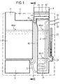
- the evaporator system 10 consists of the storage container 1, the evaporator 2, and the condensate container 3, which is arranged under the storage container 1.
- the water storage container 1 is connected by a line 5 to the evaporator 2, so that both containers communicate with one another and the water level in both containers also remains at the same level.
- a filler neck 11 is provided for filling the water into the reservoir.
- the evaporator 2 takes up a substantially smaller amount of water than that contained in the storage container 1.
- a heating element 21, which is fed through the power lines 22, is immersed in this amount of water.
- a water level sensor 24 regulates the water level W so that it does not drop below Wmin. Should the water level drop below Wmin due to the emptying of the storage container, the water level sensor 24 automatically switches off the heating element 21. According to the water level in the reservoir 1, the water level fluctuates between Wmax and Wmin and is indicated by the water level indicator 23.
- the heating element 21 can always heat only the amount of water in the evaporator 2. In this way, steam D is generated after a short switch-on time.
- an attachment 4 is placed, in which herbs K or other ethereal substances are introduced.
- the herbs K are placed on a shelf 41 designed as a sieve.
- condensate forms, which prevents the herbs K from overheating and the ethereal substances being destroyed. So that the condensate that forms does not get into the evaporator 2 and is deposited there, a collecting device for the condensate is provided.
- two inclined shields 42, 43 are arranged under the screen 41 of the attachment 4 at a distance from one another and offset.
- the shield 42 connects to the front attachment wall 47, but leaves a passage between the rear attachment wall 48 free.
- the passage is located on the side of the front attachment wall 47.
- the steam D rising from the evaporator 2 first strokes the shield 43 and passes through the passage formed to the front wall 47 between the two shields 42, 43 and finally flows between the shield 42 and the rear attachment wall 48 against the sieve 41, on which the herbs K are introduced.
- the sieve 41 and thus also the herbs K are flowed through by the steam D, which takes the etheric substances with them and conveys them to the bathroom.
- connection piece 45 and the condensate line 46 which connect the collecting channel 44 to the condensate container 3, are used.
- the evaporator system 10 is assembled into a compact apparatus and therefore requires very little space.
- the evaporator system 10 can expediently be arranged in the space between the protective grille 6 and the sauna heater 7 itself, which according to the regulations should have a width of at least 7 cm. This arrangement makes it easy and safe to operate the evaporator system 10. It is avoided to long over the hot oven 7 and yet no additional space in the bathroom is required.
- the storage container 1 and the evaporator 2 communicate.
- the water levels in the storage container 1 and in the evaporator 2 are always at the same level. This means that the water level in the evaporator 2 can fluctuate between Wmax and Wmin, depending on how strongly the reservoir 1 is filled. As a result, more and more water would have to be heated up, depending on the fill level, especially when the evaporation system was operating.
- the regulation by the water level sensor 24 can also take place in such a way that a valve is provided in the inlet line 5, which is opened depending on the desired water level, so that only a very specific amount of water is to be heated at all times.
- the line 5 can be connected directly to the tap water network, so that the water level sensor 24 regulates the water level directly from the water line with a control valve.
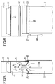
- FIGS. 5 and 6 show another embodiment of the attachment 8, the front wall being omitted in the view for a better understanding of the arrangement inside the attachment 8.
- the attachment 8 is placed on the evaporator 2, which comprises the attachment 8 in its fork-like length.
- the cover 83 forms the bottom of the attachment 8 and is pulled upwards in the middle, so that two bevels are formed which open into a passage 84.
- Above passage 84 is the upper one Cover 82 is arranged, which prevents the condensate from dripping into the passage and thus into the evaporator 2.
- the shield 83 forms a collecting channel 85 with the side walls.
- the two collecting channels 85 are brought together by a connection 87, the connection 87 being connected to the condensate container 3 by a connecting line 86.
- an evaporation system in which the steam generating container 2 and the storage container 1 are separated in order to bring only a small amount of water to the evaporation in each case.
- This evaporation system 10 can also be used advantageously without the attachment 4 with a collecting device for the condensate, just as the attachment 4 can advantageously be used without the separation of the steam generation container 2 and the water storage container 1.
- both devices combined result in the sum of the advantages and thus a particularly advantageous evaporator system.
Landscapes
- Health & Medical Sciences (AREA)
- Public Health (AREA)
- Epidemiology (AREA)
- Pain & Pain Management (AREA)
- Physical Education & Sports Medicine (AREA)
- Rehabilitation Therapy (AREA)
- Life Sciences & Earth Sciences (AREA)
- Animal Behavior & Ethology (AREA)
- General Health & Medical Sciences (AREA)
- Veterinary Medicine (AREA)
- Devices For Medical Bathing And Washing (AREA)
- Vaporization, Distillation, Condensation, Sublimation, And Cold Traps (AREA)
Abstract
Description
Die Erfindung betrifft ein Verdampfersystem für Sauna-Anlagen. Bei den bekannten Sauna-Anlagen besteht zunehmend das Bedürfnis, das übliche Sauna-Bad durch Kräuterdämpfe oder mit ätherischen Ölen angereicherte Dämpfe zu ergänzen. Hierfür sind Zusatzgeräte, sog. Verdampfersysteme, auf dem Markt, die entweder mit dem üblichen Sauna-Heizofen kombiniert sind oder auch in bestehende Anlagen nachgerüstet werden können.The invention relates to an evaporator system for sauna systems. In the known sauna systems, there is an increasing need to supplement the usual sauna bath with herbal vapors or vapors enriched with essential oils. For this purpose, additional devices, so-called evaporator systems, are on the market, which are either combined with the usual sauna heater or can also be retrofitted in existing systems.
Insbesondere für die Nachrüstung ist es erforderlich, daß das Zusatzgerät so gestaltet ist, daß es den vorhandenen Freiraum nutzt, ohne jedoch den Baderaum zu verringern. Das Zusatzgerät soll dennoch auch gut bedienbar sein, natürlich mit einem minimalen Wartungsaufwand. Eine weitere Forderung besteht darin, daß das Verdampfersystem energiesparend sein soll.In particular for retrofitting, it is necessary that the additional device is designed in such a way that it uses the available space without, however, reducing the bathing area. The additional device should still be easy to use, of course, with minimal maintenance. Another requirement is that the evaporator system should save energy.
Bei den bekannten Verdampfersystemen erfolgt das Erhitzen des Wassers zur Dampferzeugung entweder nach dem Tauchsiederprinzip, d.h. in dem Wasserbehälter ist ein Heizelement angeordnet, das direkt mit dem Wasser Kontakt hat, oder es ist ähnlich wie bei Kaffeemaschinen ein Rohr vorgesehen als Zuleitung zu dem Kräuterbehälter, in welchem zur Dampferzeugung Wasser hochsteigt und durch einen das Rohr umgebenden Heizmantel erhitzt wird.In the known evaporator systems, the water for steam generation is either heated according to the immersion heater principle, i.e. a heating element is arranged in the water container that is in direct contact with the water, or a pipe is provided, similarly to coffee machines, as a feed line to the herb container, in which rises to produce steam and is heated by a heating jacket surrounding the pipe.
Dieses letztere System hat zwar den Vorteil, daß stets nur die im Rohr befindliche Wassermenge erhitzt werden muß, andererseits ist der Wärmeübergang und damit die Heizleistung nicht so gut wie beim Tauchsiederprinzip. Zum anderen verkalken diese Rohre sehr schnell, sie sind zudem äußerst aufwendig zu reinigen bzw. zu entkalken, da das Innere des Rohres ohne Demontage nicht zugänglich ist. Wird die Reinigung zur Vermeidung dieser Umstände selten oder gar nicht durchgeführt, so sinkt der Wirkungsgrad der Heizleistung rapid ab.This latter system has the advantage that only the amount of water in the pipe has to be heated, on the other hand the heat transfer and thus the heating output is not as good as with the immersion heater principle. On the other hand, these pipes calcify very quickly, and they are also extremely difficult to clean or decalcify, since the inside of the pipe is not accessible without disassembly. If cleaning to avoid these circumstances is carried out rarely or not at all, the efficiency of the heating output drops rapidly.
Bei den bekannten Verdampfersystemen sind über bzw. in dem aufsteigenden Dampf des Dampferzeugers Schalen zur Aufnahme von Kräutern angeordnet, die durch den Dampf erhitzt werden, so daß von den Kräutern oder ätherischen Ölen Dämpfe aufsteigen, die sich dann mit dem darüber streichenden Dampf aus dem Dampferzeuger vermischen und in den Baderaum geleitet werden.In the known evaporator systems, above or in the rising steam of the steam generator, trays for receiving herbs are arranged, which are heated by the steam, so that vapors rise from the herbs or essential oils, which then pass over the steam from the steam generator mix and be led into the bathroom.
Diese Art der Beimengung der Kräuterdämpfe oder ätherischen Öle hat den Nachteil, daß über die Schale die Kräuter oder auch die ätherischen Öle zu stark erhitzt und dadurch zerstört werden. Die Ausnützung und Beimischung ist unbefriedigend. Es ist deshalb auch schon vorgesehen worden (DE 39 13 280 A1), statt einer Schale über dem Dampf ein Einlagegitter für Kräuter vorzusehen, so daß der Dampf direkt durch die Kräuter hindurchtreten kann. Dabei entsteht ein Kondensat, welches direkt in den darunterliegenden Dampferzeuger und dessen Heizelemente tropft. Bei der DE 39 13 280 A1 sind zwar unterhalb des Auflagesiebes Leitbleche vorgesehen, diese leiten jedoch das abtropfende Kondensat oder Sprühflüssigkeit direkt der Verdampferwanne zu. Es entsteht eine Verunreinigung sowohl des für die Verdampfung vorgesehenen Wassers als auch eine unerwünschte Verkrustung der Heizelemente. Der Verdampfer muß von Zeit zu Zeit gereinigt werden, um seine Funktionstüchtigkeit zu erhalten.This type of admixture of herbal vapors or essential oils has the disadvantage that the herbs or the essential oils are heated too much via the shell and are destroyed as a result. The exploitation and admixture is unsatisfactory. It has therefore already been provided (DE 39 13 280 A1) to provide an inlay grid for herbs instead of a bowl over the steam, so that the steam can pass directly through the herbs. This creates a condensate that drips directly into the steam generator underneath and its heating elements. In DE 39 13 280 A1 baffles are provided below the support sieve, but these guide the dripping condensate or spray liquid directly to the evaporator pan. There is a contamination of both the water intended for evaporation and an undesirable incrustation of the heating elements. The evaporator must be cleaned from time to time in order to maintain its functionality.
Aufgabe der vorliegenden Erfindung ist es, ein Verdampfersystem zu schaffen, das die oben aufgezeigten Nachteile des Standes der Technik vermeidet.The object of the present invention is to provide an evaporator system which avoids the disadvantages of the prior art shown above.
Erfindungsgemäß wird die Aufgabe durch die Merkmale des Anspruches 1 gelöst. Durch diese Merkmale wird sichergestellt, daß bei guter Ausnutzung und Vermischung der Kräuterdämpfe mit dem Dampf kein Kondensat in den Dampferzeugungsbehälter gelangt, diesen verschmutzt und die Heizung verkrustet. Das Verdampfungssystem ist dadurch nahezu wartungsfrei.According to the invention the object is achieved by the features of claim 1. These features ensure that when the herbal vapors are used and mixed well with the steam, no condensate gets into the steam generating container, contaminates it and encrypts the heating. The evaporation system is therefore almost maintenance-free.
Vorzugsweise besteht die Auffangeinrichtung in zwei gegeneinander versetzt und übereinander angeordneten Abschirmungen, die das Kondensat auffangen und in eine Sammelrinne ableiten, wo es gesammelt wird. Bei größeren Mengen kann auch ein Kondensatbehälter mit der Sammelrinne verbunden sein.The collecting device preferably consists of two shields which are offset from one another and arranged one above the other, which collect the condensate and discharge it into a collecting channel, where it is collected. For larger quantities, a condensate tank can also be connected to the collecting trough.
Weitere Einzelheiten der Erfindung werden anhand der Zeichnungen beschrieben.Further details of the invention will be described with reference to the drawings.
Es zeigen
- Fig. 1 -
- eine schematische Darstellung des erfindungsgemäßen Verdampfungssystems im Aufriß;
- Fig. 2 -
- eine Seitenansicht gemäß der Schnittlinie II/II in Figur 1;
- Fig. 3 -
- eine perspektivische Ansicht des Aufsatzes zur Aufnahme der Kräuter oder ätherischen Öle nebst der Auffangeinrichtung für das Kondensat;
- Fig. 4 -
- die Anordnung des Verdampfungssystems in Verbindung mit dem Sauna-Ofen.
- Fig. 5 -
- eine andere Ausführung des Aufsatzes in Seitensicht ohne Vorderwand;
- Fig. 6 -
- dieAusführung nach Fig. 5 in Frontsicht unter Weglassung der Vorderwand.
- Fig. 1 -
- a schematic representation of the evaporation system according to the invention in elevation;
- Fig. 2 -
- a side view along section line II / II in Figure 1;
- Fig. 3 -
- a perspective view of the attachment for receiving the herbs or essential oils together with the collecting device for the condensate;
- Fig. 4 -
- the arrangement of the evaporation system in connection with the sauna heater.
- Fig. 5 -
- another version of the essay in side view without front wall;
- Fig. 6 -
- 5 in front view with the front wall omitted.
Das Verdampfersystem 10 besteht aus dem Vorratsbehälter 1, dem Verdampfer 2, sowie dem Kondensatbehälter 3, der unter dem Vorratsbehälter 1 angeordnet ist. Der Wasservorratsbehälter 1 ist durch eine Leitung 5 mit dem Verdampfer 2 verbunden, so daß beide Behälter miteinander kommunizieren und sich der Wasserspiegel auch in beiden Behältern auf gleichem Niveau hält. Für das Einfüllen des Wassers in den Vorratsbehälter ist ein Einfullstutzen 11 vorgesehen.The
Der Verdampfer 2 nimmt eine wesentlich kleinere Wassermenge auf als im Vorratsbehälter 1 enthalten. In diese Wassermenge ist ein Heizelement 21 eingetaucht, das durch die Stromleitungen 22 gespeist wird. Ein Wasserstandsfühler 24 reguliert den Wasserstand W, so daß dieser nicht unter Wmin sinkt. Sollte der Wasserstand unter Wmin absinken infolge Entleerung des Vorratsbehälters, so schaltet der Wasserstandsfühler 24 automatisch das Heizelement 21 ab. Entsprechend dem Wasserstand im Vorratsbehälter 1 schwankt der Wasserstand zwischen Wmax und Wmin und wird durch den Wasserstandsanzeiger 23 angezeigt. Nachdem der Vorratsbehälter 1 vom Verdampfer 2 räumlich getrennt und nur durch die Verbindungsleitung 5 mit diesem verbunden ist, kann das Heizelement 21 stets nur die im Verdampfer 2 befindliche Wassermenge aufheizen. Auf diese Weise wird schon nach kurzer Einschaltzeit Dampf D erzeugt.The
Auf den Verdampfer 2 ist ein Aufsatz 4 aufgesetzt, in welchen Kräuter K oder andere ätherische Stoffe eingebracht werden. Die Kräuter K werden auf eine als Sieb ausgebildete Ablagefläche 41 gelegt. Der aus dem Verdampfer 2 aufsteigende Dampf D durchströmt den Aufsatz 4, dringt durch das Sieb 41 und auch durch die darauf ausgebreiteten Kräuter K, so daß ein gut durchmischter Kräuterdampf entsteht. Bei der Durchströmung entsteht Kondensat, welches verhindert, daß die Kräuter K überhitzt und die ätherischen Stoffe zerstört werden. Damit nun das sich bildende Kondensat nicht in den Verdampfer 2 gelangt und sich dort ablagert, ist eine Auffangeinrichtung für das Kondensat vorgesehen.On the
Wie aus den Figuren 2 und auch 3 hervorgeht, sind zwei geneigte Abschirmungen 42, 43 unter dem Sieb 41 des Aufsatzes 4 im Abstand voneinander und versetzt angeordnet. Die Abschirmung 42 schließt an die vordere Aufsatzwand 47 an, läßt aber einen Durchgang zwischen der hinteren Aufsatzwand 48 frei. Bei der Abschirmung 43 ist es in umgekehrter Weise: der Durchgang befindet sich an der Seite der vorderen Aufsatzwand 47. Der aus dem Verdampfer 2 aufsteigende Dampf D streicht zunächst an der Abschirmung 43 lang, gelangt durch den zu der vorderen Wand 47 gebildeten Durchgang zwischen die beiden Abschirmungen 42, 43 und strömt schließlich zwischen der Abschirmung 42 und der hinteren Aufsatzwand 48 hindurch gegen das Sieb 41, auf dem die Kräuter K eingebracht sind. Das Sieb 41 und somit auch die Kräuter K werden vom Dampf D durchströmt, der die ätherischen Stoffe mitnimmt und in den Baderaum befördert. Bildet sich nun Kondensat, so tropft dieses nach unten zunächst auf die Abschirmung 42, welche das Kondensat gegen die hintere Aufsatzwand 48 leitet. Das von dieser ersten Abschirmung 42 heruntertropfende Kondensat fällt auf die zweite Abschirmung 43 und wird durch diese gegen die hintere Aufsatzwand 48 abgeleitet und in einer Sammelrinne 44 aufgefangen. Fallen größere Kondensatmengen an, so ist es zweckmäßig, diese in einen gesonderten Kondensatbehälter 3 abzuleiten. Hierzu dient der Anschlußstutzen 45 und die Kondensatleitung 46, die die Sammelrinne 44 mit dem Kondensatbehälter 3 verbinden.As can be seen from FIGS. 2 and 3, two
Das Verdampfersystem 10 ist zu einer kompakten Apparatur zusammengebaut und benötigt deshalb äußerst wenig Platz. Das Verdampfersystem 10 kann zweckmäßigerweise in dem Raum zwischen dem Schutzgitter 6 und dem Sauna-Ofen 7 selbst angeordnet werden, der nach den Vorschriften wenigstens eine Breite von 7 cm haben soll. Durch diese Anordnung erfolgt das Bedienen des Verdampfersystems 10 bequem und gefahrlos. Es ist vermieden, über den heißen Ofen 7 zu langen und dennoch wird kein zusätzlicher Platz im Baderaum beansprucht.The
Bei der beschriebenen und in Fig. 1 dargestellten Ausführung kommunizieren der Vorratsbehälter 1 und der Verdampfer 2. Die Wasserstände im Vorratsbehälter 1 und im Verdampfer 2 halten sich stets auf dem gleichen Niveau. Das bedingt, daß im Verdampfer 2 der Wasserspiegel zwischen Wmax und Wmin schwanken kann, je nachdem, wie stark der Vorratsbehälter 1 gefüllt ist. Dadurch würde immer noch mehr Wasser in Abhängigkeit vom Füllstand gerade im Anfang des Betriebes des Verdampfungssystemes aufzuheizen sein. Vorteilhafterweise kann die Regulierung durch den Wasserstandsfühler 24 auch in der Weise erfolgen, daß ein Ventil in der Zulaufleitung 5 vorgesehen ist, das in Abhängigkeit des gewünschten Wasserstandes geöffnet wird, so daß stets nur eine ganz bestimmte Menge Wasser zu beheizen ist. Auch kann statt an den Vorratsbehälter 1 die Leitung 5 direkt an das Leitungswassernetz angeschlossen sein, so daß der Wasserstandsfühler 24 mit einem Steuerventil direkt aus der Wasserleitung den Wasserspiegel reguliert.In the embodiment described and shown in FIG. 1, the storage container 1 and the
Die Figuren 5 und 6 zeigen eine andere Ausführung des Aufsatzes 8, wobei zum besseren Verständnis der Anordnung im Inneren des Aufsatzes 8 die Vorderwand in der Ansicht jeweils weggelassen ist. Der Aufsatz 8 ist auf den Verdampfer 2 aufgesetzt, der den Aufsatz 8 in seiner Länge gabelartig umfaßt. Die Abdeckung 83 bildet den Boden des Aufsatzes 8 und ist mittig nach oben gezogen, so daß zwei Schrägen gebildet werden, die in einen Durchlaß 84 münden. Über dem Durchlaß 84 ist die obere Abdeckung 82 angeordnet, die ein Abtropfen des Kondensats in den Durchlaß und damit in den Verdampfer 2 verhindert. Die Abschirmung 83 bildet jeweils mit den Seitenwänden eine Sammelrinne 85. Die beiden Sammelrinnen 85 werden durch eine Verbindung 87 zusammengeführt, wobei die Verbindung 87 mit einer Verbindungsleitung 86 mit dem Kondensatbehälter 3 verbunden ist.FIGS. 5 and 6 show another embodiment of the
Werden ätherische Öle oder andere ätherische Flüssigkeiten eingebracht statt der Kräuter K, so ist es zweckmäßig, einen porösen Körper 81 auf das Sieb 41 zu legen, der diese ätherischen Flüssigkeiten aufnimmt und vom Dampf D durchströmt werden kann. Die Abschirmungen 42 und 43 bzw. 82 und 83 verhindern hier in gleicher Weise sowohl ein Abtropfen der ätherischen Stoffe als auch des Kondensates in den Verdampfer 2.If essential oils or other essential liquids are introduced instead of herbs K, it is expedient to place a
Bei dem beschriebenen Ausführungsbeispiel ist ein Verdampfungssystem gezeigt, bei dem Dampferzeugungsbehälter 2 und Vorratsbehälter 1 getrennt sind, um eine nur kleine Wassermenge jeweils zur Verdampfung zu bringen. Dieses Verdampfungssystem 10 kann auch ohne den Aufsatz 4 mit Auffangvorrichtung für das Kondensat vorteilhaft verwendet werden, genauso wie auch der Aufsatz 4 vorteilhaft ohne die Trennung von Dampferzeugungsbehälter 2 und Wasservorratsbehälter 1 angewandt werden kann. Beide Einrichtungen vereinigt ergeben jedoch die Summe der Vorteile und damit ein besonders vorteilhaftes Verdampfersystem.In the described embodiment, an evaporation system is shown, in which the
- 11
- WasservorratsbehälterWater reservoir
- 22nd
- VerdampferEvaporator
- 33rd
- KondensatbehälterCondensate tank
- 44th
- AufsatzEssay
- 55
- VerbindungsleitungConnecting line
- 66
- SchutzgitterProtective grille
- 77
- Ofenoven
- 88th
- anderer Aufsatzother essay
- 8181
- poröser Körperporous body
- 8282
- obere Abschirmungupper shield
- 8383
- untere Abschirmunglower shield
- 8484
- düsenförmiger Durchlaßnozzle-shaped passage
- 8585
- SammelrinneCollecting trough
- 8686
- VerbindungsleitungConnecting line
- 8787
- Verbindungconnection
- 2121
- HeizungselementHeating element
- 2222
- Anschlußleitung HeizungConnection cable heating
- 2323
- WasserstandsanzeigerWater level indicator
- 2424th
- WasserstandsfühlerWater level sensor
- 1010th
- VerdampfersystemEvaporator system
- 1111
- EinfüllstutzenFiller neck
- 4141
- SiebSieve
- 4242
- Abschirmungshielding
- 4343
- Abschirmungshielding
- 4444
- SammelrinneCollecting trough
- 4545
- AnschlußstutzenConnecting piece
- 4646
- KondensatleitungCondensate line
- 4747
- Vordere AufsatzwandFront attachment wall
- 4848
- Hintere AufsatzwandRear attachment wall
- DD
- Dampfsteam
- KK
- KräutereinlageHerbal insert
- WW
- WasserstandWater level
Claims (9)
Applications Claiming Priority (2)
| Application Number | Priority Date | Filing Date | Title |
|---|---|---|---|
| DE19606346 | 1996-02-21 | ||
| DE19606346A DE19606346C2 (en) | 1996-02-21 | 1996-02-21 | Evaporator system for sauna systems |
Publications (3)
| Publication Number | Publication Date |
|---|---|
| EP0807428A2 true EP0807428A2 (en) | 1997-11-19 |
| EP0807428A3 EP0807428A3 (en) | 1998-03-25 |
| EP0807428B1 EP0807428B1 (en) | 2001-11-28 |
Family
ID=7785945
Family Applications (1)
| Application Number | Title | Priority Date | Filing Date |
|---|---|---|---|
| EP97102482A Expired - Lifetime EP0807428B1 (en) | 1996-02-21 | 1997-02-15 | Steam generator for saunas |
Country Status (4)
| Country | Link |
|---|---|
| EP (1) | EP0807428B1 (en) |
| AT (1) | ATE209476T1 (en) |
| DE (2) | DE19606346C2 (en) |
| ES (1) | ES2169283T3 (en) |
Cited By (1)
| Publication number | Priority date | Publication date | Assignee | Title |
|---|---|---|---|---|
| WO2008129119A1 (en) | 2007-04-19 | 2008-10-30 | Pertti Harvia | Steam generator, method for operating a steam generator and a vessel of a steam generator |
Families Citing this family (8)
| Publication number | Priority date | Publication date | Assignee | Title |
|---|---|---|---|---|
| DE29716620U1 (en) * | 1997-09-16 | 1997-11-13 | Meier, Hansjürgen, 32339 Espelkamp | Installable device for generating steam for a shower cubicle |
| DE20103108U1 (en) * | 2001-02-21 | 2002-07-04 | Klafs Saunabau GmbH & Co Medizinische Technik, 74523 Schwäbisch Hall | Sauna heater with evaporator device |
| DE20103253U1 (en) * | 2001-02-23 | 2002-07-04 | Klafs Saunabau GmbH & Co Medizinische Technik, 74523 Schwäbisch Hall | Evaporator unit for a sauna or steam bath cabin and filling vessel |
| DE10259260A1 (en) * | 2002-12-12 | 2004-06-24 | Hansgrohe Ag | Device for generating fragrance comprises a steam generator, a main steam line from the steam generator to a steam outlet, a container with a housing for aromatic supports, and a steam supply line from the steam generator into the container |
| DE202005019488U1 (en) * | 2005-12-13 | 2007-04-19 | Hans Einhell Ag | sauna heater |
| DE102008026473A1 (en) | 2008-06-03 | 2009-12-10 | Dannenmann, Gudrun | Oven for sauna, has infrared thermal heater attached and fitted individually, multilaterally or all around, where infrared thermal heater of thermal zone is alternatively equipped with electrical heating foil, heating cable or heating plate |
| DE102012019875A1 (en) | 2012-10-10 | 2014-04-10 | Johanna Bozena Dannenmann | Sauna heating device has steam unit for use as dry or wet bathing form combined with light or colored light for color therapy, and sauna ovens, on whose outer casing additional device of illumination body is equipped |
| EP3569215B1 (en) | 2018-05-17 | 2020-09-09 | Klafs GmbH & Co. KG | Cabin for sauna |
Family Cites Families (8)
| Publication number | Priority date | Publication date | Assignee | Title |
|---|---|---|---|---|
| US2332402A (en) * | 1941-07-25 | 1943-10-19 | Seikowitz Jack | Therapeutic device |
| DE3109540A1 (en) * | 1981-03-13 | 1982-09-23 | Eberhard Hoesch & Söhne Kunststoffwerk KG, 5160 Düren | STEAM OUTLET FOR A STEAM BATH |
| DE3404892A1 (en) * | 1984-02-11 | 1985-08-14 | Dannenmann, Gudrun, 7060 Schorndorf | Sauna oven |
| CH674144A5 (en) * | 1987-10-01 | 1990-05-15 | Josef Balthasar Arnold | |
| DE3913280C2 (en) * | 1989-04-22 | 1995-02-16 | Paul Haslauer | Vaporizer |
| GB2241051B (en) * | 1990-02-19 | 1994-05-18 | Helo Tehtaat Oy | An electric sauna heater |
| DE4132042A1 (en) * | 1991-09-26 | 1993-04-01 | Dannenmann Gudrun | Automatic regulator of water level in sauna and steam bath evaporator - generates vacuum in sealed supply tank which is vented by falling level in evaporator. |
| DE4328376A1 (en) * | 1993-08-24 | 1995-03-16 | Dannenmann Gudrun | Device for the evaporation of liquid |
-
1996
- 1996-02-21 DE DE19606346A patent/DE19606346C2/en not_active Expired - Fee Related
-
1997
- 1997-02-15 EP EP97102482A patent/EP0807428B1/en not_active Expired - Lifetime
- 1997-02-15 ES ES97102482T patent/ES2169283T3/en not_active Expired - Lifetime
- 1997-02-15 AT AT97102482T patent/ATE209476T1/en not_active IP Right Cessation
- 1997-02-15 DE DE59705494T patent/DE59705494D1/en not_active Expired - Fee Related
Cited By (1)
| Publication number | Priority date | Publication date | Assignee | Title |
|---|---|---|---|---|
| WO2008129119A1 (en) | 2007-04-19 | 2008-10-30 | Pertti Harvia | Steam generator, method for operating a steam generator and a vessel of a steam generator |
Also Published As
| Publication number | Publication date |
|---|---|
| EP0807428A3 (en) | 1998-03-25 |
| DE59705494D1 (en) | 2002-01-10 |
| ATE209476T1 (en) | 2001-12-15 |
| DE19606346A1 (en) | 1997-08-28 |
| ES2169283T3 (en) | 2002-07-01 |
| EP0807428B1 (en) | 2001-11-28 |
| DE19606346C2 (en) | 1998-07-16 |
Similar Documents
| Publication | Publication Date | Title |
|---|---|---|
| EP0383327B1 (en) | Cooking steam generator with a descaling device | |
| DE2419734B2 (en) | SELF-CLEANING STEAM IRON | |
| DE69118036T2 (en) | Device for supplying boiling water | |
| EP3225139A1 (en) | Vaporiser device for water | |
| EP0807428B1 (en) | Steam generator for saunas | |
| DE3526186A1 (en) | ELECTRIC HEATING FOR LIQUID TANKS | |
| DE3015677C2 (en) | Device for collecting cleaning bodies used to clean a tubular heat exchanger | |
| DE1794237A1 (en) | Falling film evaporator | |
| DE3109540A1 (en) | STEAM OUTLET FOR A STEAM BATH | |
| EP0363708A2 (en) | Heating apparatus for agents fluids | |
| EP0609853B1 (en) | Heat generator for hot water production and heating | |
| DE69403127T2 (en) | Coffee machine with water return shaft | |
| DE19642106C1 (en) | Equipment for discontinuous preparation of farinaceous products, such as spaghetti or similar | |
| DE1817352A1 (en) | Device for generating steam for air humidification | |
| DE2741719C3 (en) | Electric coffee or tea machine | |
| EP0011290A1 (en) | Expresso coffee machine | |
| DE3214064A1 (en) | DEVICE FOR VAPOR DISCHARGING ON A MASH AND / OR ROOT PANS | |
| DE2701692A1 (en) | Electric flow heater for coffee or tea making machines - has flow pipes in thermal contact with tubular heating element welded to heat conducting plates | |
| EP3805648A1 (en) | Household appliance and evaporator system for a household appliance | |
| DE1926814A1 (en) | Water purifier | |
| EP0454744B1 (en) | Device for supplying hot water | |
| DE3715132A1 (en) | Hot steam condenser and heat recovery installation | |
| AT411142B (en) | GETRÄNKEERHITZER | |
| EP1916928B1 (en) | Steam cooking appliance | |
| DE1579355C (en) | Hot water heaters for coffee machines |
Legal Events
| Date | Code | Title | Description |
|---|---|---|---|
| PUAI | Public reference made under article 153(3) epc to a published international application that has entered the european phase |
Free format text: ORIGINAL CODE: 0009012 |
|
| AK | Designated contracting states |
Kind code of ref document: A2 Designated state(s): AT CH DE ES FI FR IT LI NL |
|
| PUAL | Search report despatched |
Free format text: ORIGINAL CODE: 0009013 |
|
| AK | Designated contracting states |
Kind code of ref document: A3 Designated state(s): AT CH DE ES FI FR IT LI NL |
|
| 17P | Request for examination filed |
Effective date: 19980923 |
|
| GRAG | Despatch of communication of intention to grant |
Free format text: ORIGINAL CODE: EPIDOS AGRA |
|
| 17Q | First examination report despatched |
Effective date: 20010222 |
|
| GRAG | Despatch of communication of intention to grant |
Free format text: ORIGINAL CODE: EPIDOS AGRA |
|
| GRAH | Despatch of communication of intention to grant a patent |
Free format text: ORIGINAL CODE: EPIDOS IGRA |
|
| GRAH | Despatch of communication of intention to grant a patent |
Free format text: ORIGINAL CODE: EPIDOS IGRA |
|
| GRAA | (expected) grant |
Free format text: ORIGINAL CODE: 0009210 |
|
| AK | Designated contracting states |
Kind code of ref document: B1 Designated state(s): AT CH DE ES FI FR IT LI NL |
|
| PG25 | Lapsed in a contracting state [announced via postgrant information from national office to epo] |
Ref country code: NL Free format text: LAPSE BECAUSE OF FAILURE TO SUBMIT A TRANSLATION OF THE DESCRIPTION OR TO PAY THE FEE WITHIN THE PRESCRIBED TIME-LIMIT Effective date: 20011128 |
|
| REF | Corresponds to: |
Ref document number: 209476 Country of ref document: AT Date of ref document: 20011215 Kind code of ref document: T |
|
| REG | Reference to a national code |
Ref country code: CH Ref legal event code: EP |
|
| REF | Corresponds to: |
Ref document number: 59705494 Country of ref document: DE Date of ref document: 20020110 |
|
| REG | Reference to a national code |
Ref country code: CH Ref legal event code: NV Representative=s name: SPIERENBURG HELMLE-KOLB & PARTNER AG PATENT- UND M |
|
| PGFP | Annual fee paid to national office [announced via postgrant information from national office to epo] |
Ref country code: DE Payment date: 20020312 Year of fee payment: 6 |
|
| PGFP | Annual fee paid to national office [announced via postgrant information from national office to epo] |
Ref country code: FR Payment date: 20020322 Year of fee payment: 6 |
|
| PGFP | Annual fee paid to national office [announced via postgrant information from national office to epo] |
Ref country code: ES Payment date: 20020325 Year of fee payment: 6 Ref country code: CH Payment date: 20020325 Year of fee payment: 6 Ref country code: AT Payment date: 20020325 Year of fee payment: 6 |
|
| PGFP | Annual fee paid to national office [announced via postgrant information from national office to epo] |
Ref country code: FI Payment date: 20020328 Year of fee payment: 6 |
|
| NLV1 | Nl: lapsed or annulled due to failure to fulfill the requirements of art. 29p and 29m of the patents act | ||
| ET | Fr: translation filed | ||
| REG | Reference to a national code |
Ref country code: ES Ref legal event code: FG2A Ref document number: 2169283 Country of ref document: ES Kind code of ref document: T3 |
|
| PLBE | No opposition filed within time limit |
Free format text: ORIGINAL CODE: 0009261 |
|
| STAA | Information on the status of an ep patent application or granted ep patent |
Free format text: STATUS: NO OPPOSITION FILED WITHIN TIME LIMIT |
|
| 26N | No opposition filed | ||
| PG25 | Lapsed in a contracting state [announced via postgrant information from national office to epo] |
Ref country code: FI Free format text: LAPSE BECAUSE OF NON-PAYMENT OF DUE FEES Effective date: 20030215 Ref country code: AT Free format text: LAPSE BECAUSE OF NON-PAYMENT OF DUE FEES Effective date: 20030215 |
|
| PG25 | Lapsed in a contracting state [announced via postgrant information from national office to epo] |
Ref country code: ES Free format text: LAPSE BECAUSE OF NON-PAYMENT OF DUE FEES Effective date: 20030217 |
|
| PG25 | Lapsed in a contracting state [announced via postgrant information from national office to epo] |
Ref country code: LI Free format text: LAPSE BECAUSE OF NON-PAYMENT OF DUE FEES Effective date: 20030228 Ref country code: CH Free format text: LAPSE BECAUSE OF NON-PAYMENT OF DUE FEES Effective date: 20030228 |
|
| PG25 | Lapsed in a contracting state [announced via postgrant information from national office to epo] |
Ref country code: DE Free format text: LAPSE BECAUSE OF NON-PAYMENT OF DUE FEES Effective date: 20030902 |
|
| REG | Reference to a national code |
Ref country code: CH Ref legal event code: PL |
|
| PG25 | Lapsed in a contracting state [announced via postgrant information from national office to epo] |
Ref country code: FR Free format text: LAPSE BECAUSE OF NON-PAYMENT OF DUE FEES Effective date: 20031031 |
|
| REG | Reference to a national code |
Ref country code: FR Ref legal event code: ST |
|
| REG | Reference to a national code |
Ref country code: ES Ref legal event code: FD2A Effective date: 20030217 |
|
| PG25 | Lapsed in a contracting state [announced via postgrant information from national office to epo] |
Ref country code: IT Free format text: LAPSE BECAUSE OF NON-PAYMENT OF DUE FEES Effective date: 20050215 |