EP0806820B1 - Eine Methode für die Herstellung eines Kabelbaums und Kabelbaumherstellungsapparat - Google Patents
Eine Methode für die Herstellung eines Kabelbaums und Kabelbaumherstellungsapparat Download PDFInfo
- Publication number
- EP0806820B1 EP0806820B1 EP97107674A EP97107674A EP0806820B1 EP 0806820 B1 EP0806820 B1 EP 0806820B1 EP 97107674 A EP97107674 A EP 97107674A EP 97107674 A EP97107674 A EP 97107674A EP 0806820 B1 EP0806820 B1 EP 0806820B1
- Authority
- EP
- European Patent Office
- Prior art keywords
- wires
- wire
- loosened
- placing table
- length adjusting
- Prior art date
- Legal status (The legal status is an assumption and is not a legal conclusion. Google has not performed a legal analysis and makes no representation as to the accuracy of the status listed.)
- Expired - Lifetime
Links
- 238000004519 manufacturing process Methods 0.000 title claims description 13
- 238000000034 method Methods 0.000 claims description 17
- 238000005452 bending Methods 0.000 claims description 13
- 238000003825 pressing Methods 0.000 claims description 5
- 239000010408 film Substances 0.000 description 30
- 238000010586 diagram Methods 0.000 description 7
- 239000004698 Polyethylene Substances 0.000 description 4
- 239000004020 conductor Substances 0.000 description 4
- 229920000573 polyethylene Polymers 0.000 description 4
- 239000000853 adhesive Substances 0.000 description 3
- 230000001070 adhesive effect Effects 0.000 description 3
- 230000008859 change Effects 0.000 description 3
- 238000000576 coating method Methods 0.000 description 3
- 239000004642 Polyimide Substances 0.000 description 2
- 239000004734 Polyphenylene sulfide Substances 0.000 description 2
- 239000002390 adhesive tape Substances 0.000 description 2
- 238000010276 construction Methods 0.000 description 2
- 238000005530 etching Methods 0.000 description 2
- 230000001965 increasing effect Effects 0.000 description 2
- 239000011295 pitch Substances 0.000 description 2
- -1 polyethylene Polymers 0.000 description 2
- 229920001721 polyimide Polymers 0.000 description 2
- 229920000069 polyphenylene sulfide Polymers 0.000 description 2
- 239000004800 polyvinyl chloride Substances 0.000 description 2
- 235000008733 Citrus aurantifolia Nutrition 0.000 description 1
- 239000004809 Teflon Substances 0.000 description 1
- 229920006362 Teflon® Polymers 0.000 description 1
- 240000006909 Tilia x europaea Species 0.000 description 1
- 235000011941 Tilia x europaea Nutrition 0.000 description 1
- 230000009471 action Effects 0.000 description 1
- 239000011248 coating agent Substances 0.000 description 1
- 230000010485 coping Effects 0.000 description 1
- 239000013039 cover film Substances 0.000 description 1
- 238000005520 cutting process Methods 0.000 description 1
- 230000001419 dependent effect Effects 0.000 description 1
- 230000003028 elevating effect Effects 0.000 description 1
- NBVXSUQYWXRMNV-UHFFFAOYSA-N fluoromethane Chemical compound FC NBVXSUQYWXRMNV-UHFFFAOYSA-N 0.000 description 1
- 239000004571 lime Substances 0.000 description 1
- 239000000463 material Substances 0.000 description 1
- 230000007246 mechanism Effects 0.000 description 1
- 239000002184 metal Substances 0.000 description 1
- 230000008569 process Effects 0.000 description 1
- 229920005989 resin Polymers 0.000 description 1
- 239000011347 resin Substances 0.000 description 1
- 229920001169 thermoplastic Polymers 0.000 description 1
- 229920001187 thermosetting polymer Polymers 0.000 description 1
- 239000004416 thermosoftening plastic Substances 0.000 description 1
Images


Classifications
-
- H—ELECTRICITY
- H01—ELECTRIC ELEMENTS
- H01R—ELECTRICALLY-CONDUCTIVE CONNECTIONS; STRUCTURAL ASSOCIATIONS OF A PLURALITY OF MUTUALLY-INSULATED ELECTRICAL CONNECTING ELEMENTS; COUPLING DEVICES; CURRENT COLLECTORS
- H01R43/00—Apparatus or processes specially adapted for manufacturing, assembling, maintaining, or repairing of line connectors or current collectors or for joining electric conductors
- H01R43/04—Apparatus or processes specially adapted for manufacturing, assembling, maintaining, or repairing of line connectors or current collectors or for joining electric conductors for forming connections by deformation, e.g. crimping tool
- H01R43/048—Crimping apparatus or processes
- H01R43/052—Crimping apparatus or processes with wire-feeding mechanism
-
- H—ELECTRICITY
- H01—ELECTRIC ELEMENTS
- H01R—ELECTRICALLY-CONDUCTIVE CONNECTIONS; STRUCTURAL ASSOCIATIONS OF A PLURALITY OF MUTUALLY-INSULATED ELECTRICAL CONNECTING ELEMENTS; COUPLING DEVICES; CURRENT COLLECTORS
- H01R43/00—Apparatus or processes specially adapted for manufacturing, assembling, maintaining, or repairing of line connectors or current collectors or for joining electric conductors
- H01R43/28—Apparatus or processes specially adapted for manufacturing, assembling, maintaining, or repairing of line connectors or current collectors or for joining electric conductors for wire processing before connecting to contact members, not provided for in groups H01R43/02 - H01R43/26
-
- Y—GENERAL TAGGING OF NEW TECHNOLOGICAL DEVELOPMENTS; GENERAL TAGGING OF CROSS-SECTIONAL TECHNOLOGIES SPANNING OVER SEVERAL SECTIONS OF THE IPC; TECHNICAL SUBJECTS COVERED BY FORMER USPC CROSS-REFERENCE ART COLLECTIONS [XRACs] AND DIGESTS
- Y10—TECHNICAL SUBJECTS COVERED BY FORMER USPC
- Y10T—TECHNICAL SUBJECTS COVERED BY FORMER US CLASSIFICATION
- Y10T29/00—Metal working
- Y10T29/49—Method of mechanical manufacture
- Y10T29/49002—Electrical device making
- Y10T29/49117—Conductor or circuit manufacturing
- Y10T29/49174—Assembling terminal to elongated conductor
- Y10T29/49181—Assembling terminal to elongated conductor by deforming
-
- Y—GENERAL TAGGING OF NEW TECHNOLOGICAL DEVELOPMENTS; GENERAL TAGGING OF CROSS-SECTIONAL TECHNOLOGIES SPANNING OVER SEVERAL SECTIONS OF THE IPC; TECHNICAL SUBJECTS COVERED BY FORMER USPC CROSS-REFERENCE ART COLLECTIONS [XRACs] AND DIGESTS
- Y10—TECHNICAL SUBJECTS COVERED BY FORMER USPC
- Y10T—TECHNICAL SUBJECTS COVERED BY FORMER US CLASSIFICATION
- Y10T29/00—Metal working
- Y10T29/51—Plural diverse manufacturing apparatus including means for metal shaping or assembling
- Y10T29/5193—Electrical connector or terminal
-
- Y—GENERAL TAGGING OF NEW TECHNOLOGICAL DEVELOPMENTS; GENERAL TAGGING OF CROSS-SECTIONAL TECHNOLOGIES SPANNING OVER SEVERAL SECTIONS OF THE IPC; TECHNICAL SUBJECTS COVERED BY FORMER USPC CROSS-REFERENCE ART COLLECTIONS [XRACs] AND DIGESTS
- Y10—TECHNICAL SUBJECTS COVERED BY FORMER USPC
- Y10T—TECHNICAL SUBJECTS COVERED BY FORMER US CLASSIFICATION
- Y10T29/00—Metal working
- Y10T29/53—Means to assemble or disassemble
- Y10T29/5313—Means to assemble electrical device
- Y10T29/532—Conductor
- Y10T29/53209—Terminal or connector
- Y10T29/53213—Assembled to wire-type conductor
Definitions
- the present invention relates to a method for producing a wiring harness and a wiring harness producing apparatus, e.g. used in an internal wiring of an office automation (OA) equipment, a home electric appliance or an automotive vehicle.
- OA office automation
- US-A-5 230 146 discloses a method for assembling a wire harness and an apparatus for carrying out the method.
- Main wires are arranged horizontally and in parallel with each other. A required portion of each main wire held by a cover installed at the leading end portion of a rod is dropped to a predetermined lower portion so as to obtain a branch wire.
- a known wiring harness for electrical connection arranged in an OA equipment, a home electric appliance or an automotive vehicle has conventionally been mounted as follows. Specifically, a plurality of wires 1 for connecting a CPU, a display device and a variety of switches are bundled, e.g. as shown in FIG.
- jigs (not shown) or the like for holding a connector 3 and the wires 1 are arranged on a flat plate in accordance with an actual arrangement of the wiring harness; the wires 1 are arranged in accordance with the jigs; an adhesion tape 2 for protection is wound around the bundle of wires 1; the taped wire bundle is covered with a casing to be held in a specified configuration; and the cased wire bundle is so mounted as to conform to a wiring path inside an OA equipment, a home electric appliance or an automotive vehicle (first prior art).
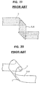
- FIG. 19 there is also a known method for linearly arranging a plurality of strip-like conductors 1 in parallel with each other, laying films 5, 6 on the opposite sides of the conductors 1, and folding the thus obtained flat cable according to a wiring path (third prior art).
- the apparatuses required for the second prior art can be dispensed with.
- folded portions 7 may be damaged or a portion between the folded portions 7 may be deformed in such a three-dimensional manner to part from the remaining parts of the wiring harness due to the elastic restoration of the folded portions 7 as shown in FIG. 20. This presents a problem that the configuration of the wiring harness cannot stably conform to the wiring path.
- the respective conductors 1 may accurately be arranged along the wiring path into a corresponding configuration and at specified intervals. However, this requires a large amount of time for aligning the configuration of the conductors 1, leading to a poor time efficiency. Further, since a large film corresponding to the wiring path is required, the problem of the second prior art is left unsolved.
- An object of the present invention is to provide a wiring harness, a method for producing a wiring harness and a wiring harness producing apparatus having or allowing for a simple construction of the apparatus, which is capable of easily producing a wiring harness without folding or bending and easily coping with a design change.
- a method for producing a wiring harness comprising:
- the method comprises a fourth step of establishing the desired position or configuration of the curved and linear portions of the wiring harness and adhering the protection film to the curved portion.
- the plurality of wires are arranged to extend over an opening which is provided in a predetermined or predeterminable position of a surface of a placing table means and, in particular in the second step, the respective wires are pushed into the opening using the loosened length adjusting means.
- an apparatus for producing a wiring harness comprising:
- steps or recesses have a specified inclination, which is defined in accordance with the desired setting of the different loosened lengths of the respective wires.
- the apparatus further comprises wire aligning means for substantially parallelly aligning the plurality of wires fed from the wire feeding means.
- At least one opening is formed in a predetermined or predeterminable position of a surface of the placing table means, in particular in a placing table module thereof or between two adjacent placing table modules thereof, through or into which the loosened length adjusting means is movable to push the respective wires after being brought into contact with the respective wire positioning means, in particular steps or recesses, thereof, wherein the opening has preferably a width along the longitudinal direction of the wires such that the wires are smoothly bent when they are pushed by the respective wire positioning means.
- the placing table means further comprises a sheet member adhering table module for adhering a sheet member to the linear portion of the plurality of wires after the setting of the different loosened lengths and/or a protection film adhering table module for adhering a protection film to the curved portion of the plurality of wires.
- the placing table means further comprises at least one connector connecting table module for connecting at least one connector with at least a part of the plurality of wires after the setting of the different loosened lengths thereof by the loosened length adjusting means.
- the portion of the loosened length adjusting means coming into contact with the wires and/or the edges of the placing table means is/are rounded off.
- the height hn can be determined within a predetermined level of accuracy.
- the wire positioning means in particular the steps or recesses are spaced from each other, preferably in the lateral direction of the loosened length adjusting means, depending upon or in correspondence with the spacing(s) of the wires.
- a wiring harness producing apparatus comprising:
- the wiring harness producing apparatus can be changed in various manners by changing their combination. This leads to an enhanced degree of freedom in designing wiring harnesses.
- an opening for allowing the tool or loosened length adjusting means to set the loosened lengths by being brought into contact with the wires and pushing them down is formed in a specified position of the upper surface of the placing table.
- the plurality of wires are linearly placed in parallel with each other on the placing table to extend over the opening, and the loosened length adjusting means is brought into contact with the wires and pushed down in the opening to set the loosened lengths for the respective wires. Accordingly, the wires are allowed to have a curved portion corresponding to a desired wiring path only by a very easy operation.
- the opening for allowing the tool or loosened length adjusting means to set the loosened lengths by being brought into contact with the wires and pushing them down is formed in the specified position of the upper surface of the placing table. Accordingly, the plurality of wires are linearly placed in parallel with each other on the placing table to extend over the opening, and the loosened length adjusting means is brought into contact with the wires and pushed down in the opening to set the loosened lengths for the respective wires. Therefore, the wires are advantageously allowed to have a curved portion corresponding to a desired wiring path only by a very easy operation.
- a plurality of wires are linearly placed in parallel with each other on a placing table, and a tool formed with steps with a specified inclination is pressed against the wires to set different loosened lengths for the respective wires.
- a tool formed with steps with a specified inclination is pressed against the wires to set different loosened lengths for the respective wires.
- a film is or may be adhered to the plurality of wires having the loosened lengths thereof set in order to hold the different loosened lengths unchanged.
- an opening is formed in a specified position of the upper surface of the placing table.
- the plurality of wires are linearly placed in parallel with each other to extend over the opening, and the loosened lengths are set by bringing the tool into contact with the wires and pushing them down in the opening.
- a curved portion in conformity with a desired wiring path can be formed by the respective wires only by a very easy operation.
- an opening for allowing the tool or loosened length adjusting means to set the loosened lengths by being brought into contact with the wires and pushing them down is formed in a specified position of the upper surface of the placing table.
- the wiring harness producing apparatus further comprises a film adhering table for adhering a film to the plurality of wires having been loosened by the different lengths.
- a film adhering table for adhering a film to the plurality of wires having been loosened by the different lengths.
- the film can easily be adhered.
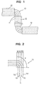
- FIG. 1 is a diagram of a wiring harness produced by a producing apparatus according to one embodiment of the invention.
- this wiring harness a plurality of wires 11 are arranged substantially in parallel at substantially even intervals on the same plane, and are partly fixed by adhering films 12.
- Films 12 which may be used to fix the wires 11 and may be made of, e.g. polyvinyl chloride (PVC), polyethylene (PE) or a thin metal plate are adhered to parts of the wires from above using a cold adhesive or thermoplastic adhesive.
- PVC polyvinyl chloride
- PE polyethylene
- thermoplastic adhesive e.g. thermoplastic adhesive
- all wires 11 are curved along substantially concentric arcs at substantially even intervals in each curved portion 13.
- the films 12 may be adhered to linear portions 13b of the wires 11, but not to the curved portions 13a thereof. Therefore, the respective wires 11 used are of the type which are covered with insulating coatings made of polyvinyl chloride (PVC) or polyethylene (PE).
- PVC polyvinyl chloride
- PE polyethylene
- the wiring harness may be required to be heat resistant.
- a fluorocarbon resin (Trademark: "Teflon”) may be used as a coating material of the wires 11; enamelled wires may be used as wires 11; polyimide (PI) or polyphenylene sulfide (PPS) as a product may be used as films 12 and the wires 11 and the films 12 may be fixed using a thermosetting adhesive.
- the respective wires 11 used are of the type which are covered with insulating coatings.
- the number of the wires 11 is not limited to four provided that the wires 11 are arranged in substantially parallel at preferably even intervals or spacings or pitches on the same plane, at least within predetermined tolerances. Also substantially uneven intervals of the wires 11 may be chosen, i.e. the wires 11 must not be equally spaced.
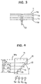
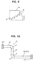
- FIG. 2 is a diagram showing the wires 11 the longitudinal direction thereof is curved by an angle of 90° in the curved portion 13. Since the wires 11 (11a to 11d) are spaced by a specified distance w in the curved portion 13 of the wiring harness, the lengths of the wires 11 need to be different or to have different lengths.
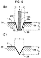
- a wire length adjusting tool or means 14 (loosened length adjusting means, shown in FIG. 4) formed with bevelled portions or grooves or recesses or steps 15 of specified height ⁇ H at predetermined or predeterminable intervals (w) of the wires 11a to 11d is used to push or displace the wires 11a to 11d in a predetermined or predeterminable direction, e.g. down, to loosen them by specified lengths, thereby suitably adjusting the lengths of the wires 11a to 11d to form the curved portion 13 as indicated by solid lines in FIG. 3.
- the respective steps 15 of the wire length adjusting tool 14 are substantially in the form of an arcuate recess so as to prevent the wires 11a to 11d from getting out of the steps 15.
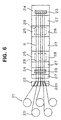
- a producing apparatus preferably used is as shown in FIG. 6.
- This apparatus includes a wire feeder 21 (wire feeding means) having a plurality of wire feeding drums 20 (of which five are shown as an example) to simultaneously feed the wires 11, a wire aligning unit 22 (wire aligning means) formed with grooves 22a for aligning the spacing (w) of the plurality of fed wires 11, connector connecting units 24 (connector connecting tables or placing table means) generally in use for connecting a specified connector 23 with the wires 11 and/or for placing the wires 11 in a predetermined or predeterminable arrangement, circuit or wire length adjusting units 25 for adjusting the length of the respective wires 11 (11a to 11d) forming circuits, preferably using the aforementioned wire length adjusting tool 14, and wire arrangement tables 27 (film adhering tables or wire portion fixing units) for fixing or securing fixing means 12 to predetermined or predeterminable portions or positions of the wires 11, preferably for adhering (or applying) films 12 or the like holding means to the wires 11 between the connector connecting unit 24
- each circuit length adjusting unit 25 an opening 29 for allowing the wires 11 to be pushed down by the wire length adjusting tool 14 to be loosened is formed in the middle of the upper surface of a placing table 28 as shown in FIG. 5.
- the wire aligning unit 22, the connector connecting units 24, the placing tables 28 of the circuit length adjusting units 25 and the wire arrangement tables 27 are set to have substantially the same height. These units are detachable as individual units so that their combination can easily be changed in accordance with a wiring path or may be unitarily or integrally formed.
- the tip or extremity 15r of the step or recess 15 may be rounded of as shown in FIG. 5(B) as phantom line for avoiding damages to the wires 11 and for reducing even more the deviations or errors, when calculating the height hn of the steps 15 by the above simplified formula or equation (FIG. 5(C)).
- the edges 28r of the placing table means or units 28 may be rounded off (FIG. 5(B)) for avoiding damages to the wires 11 and allowing for a smooth bending thereof, when the length adjusting means 14 are inserted into the opening 29.
- the opening 29 should have such a width a, that the wires 11 are not damaged, when the wire length adjusting tool 14 is inserted thereinto, in particular for avoiding wedging or clipping of the wires 11 by the edges of the wire length adjusting tool 14 and/or damages caused by a too strong bending of the wires 11, when the gap or interstice or clearance between the edge of the placing table means or connector connecting unit 24 and the loosened length adjusting means 14 is too small.
- the opening 29 has such a width a along the feeding direction P or longitudinal direction of the wires 11, that the wire length adjusting tool 14 can be loosely fitted or inserted into the opening 29 with the wires 11 arranged therebetween such that the wires 11 are not damaged, e.g. by wedging, buckling or too strong bending.
- the steps or recesses or bevelled portions 15 may be spaced according to the distance or pitch of the wires 11.
- the distance w between the wires 11 is equal for all the wires 11 and thus the corresponding steps 15 are equally spaced from each other.
- the steps 15 are correspondingly also not equally spaced.
- the steps or recesses or bevelled portions 15 are formed in correspondence to the positions of the respective wires 11 to be displaced.
- the wire length adjusting tool 14 is produced or formed having an inclined side, into which recesses 15 are formed in accordance with the corresponding position of the wires 11 to be displaced.
- the wires 11 are fed from the plurality of wire feeding drums 20 of the wire feeder 21, and are linearly placed in parallel with each other on the upper surfaces of the connector connecting units 24, of the placing tables 28 of the circuit length adjusting units 25, and of the wire arrangement tables 27 while being passed along the grooves 22a of the wire aligning unit 22 so as to space the wires 11 by a specified width w.
- the steps 15 of the wire length adjusting tool 14 are brought into contact with the wires 11 (11a to 11d) extending in or over the opening 29 preferably in the middle of the placing table 28 as shown in FIG. 5, and pushed down by a specified distance to loosen the wires 11a to 11d by the distances corresponding to height hn of the respective steps 15.
- the wires 11 are fed from the respective wire feeding drums 20 by the loosened lengths.
- the wire length adjusting tool 14 may be automatically pushed down using an electrically or electronically controlled elevating device and/or manually pushed down by an operator.
- the specified films or fixing means 12 are adhered to the wires 11 from above at the wire arrangement tables 27 to fix the wires 11, in particular in or at the linear portions of the wires 11, and the specified connectors 23 are connected with the wires 11 by the connector connecting units 24, thereby completing the wiring harness shown in FIG. 1.
- Hard molded parts may be used instead of the aforementioned films 12.
- the molded parts are provided with a locking mechanism used to mount the wiring harness on an apparatus such as an OA equipment, a home electric appliance or an automotive vehicle, the wiring harness can easily be mounted in a later process.
- the height difference ( ⁇ Hn) between adjacent steps 15 of the wire length adjusting tool 14 may be so set as to conform to the difference ( L n - L n -1 ) in length between the wires 11 as follows.
- the inclination ⁇ of the steps 15 may be constant for n sufficiently big, e.g. n ⁇ 4.
- the wires 11a to 11d can be adjusted in length by being loosened by the lengths suited to forming the curved portion 13. Accordingly, the wires 11a to 11d can be arranged within a short period of time without requiring a work space and without being folded as in the third prior art.
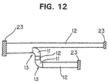
- wire aligning unit 22, the connector connecting units 24, the placing tables 28 of the circuit length adjusting units 25, and the wire arrangement tables 27 are detachable as individual units, wiring harnesses corresponding to a variety of wiring paths can be fabricated by changing their combination in various manners. For example, if a part 12a of the wiring harness where the film 12 is adhered is wished to be elongated as shown in FIG. 10, a plurality of wire arrangement tables 27 may be juxtaposed as indicated by Ar1 in FIG. 11 or a differently specified wire arrangement table (not shown) having a different length may be set. Further, if some of the plurality of wires 11 are branched from the rest and only the branched wires 11 are curved (as shown in FIG.
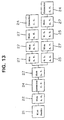
- the connector connecting units 24, the circuit length adjusting units 25, the wire arrangement tables 27, etc. may be so rearranged as to conform to a design of the wiring path as shown in FIG. 13. Since the respective units are detachable as individual units, a degree of freedom in designing wiring harnesses can be enhanced by changing the combination of the units in various manners.
- the number of the circuit length adjusting units 25 may be increased so as to conform to the number of the curved portions 13. Further, if the distance between the curved portions 13 is changed in the case that there are a plurality of curved portions 13, the producing apparatus may be designed by changing, e.g. the distance between the connector connecting unit 24 and the circuit length adjusting unit 25.
- wires 11 having being loosened by specified lengths to form the curved portions 13 are arranged on the same plane in FIG. 1, they may be arranged while being curved in a three-dimensional manner.
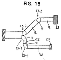
- the wire harness may have several branches being differently oriented e.g. by having different bent portions 13-1 and 13-2 having different angles (90° for the lower branch of FIG. 14(B) and 45° for the upper branch in FIG. 14(B)). These different bent portions 13-1 and 13-2 may be obtained by using the wire length adjusting tool 14 of FIG. 14(A).
- the wire length adjusting tool 14 may be arranged at an angle substantially different from 90° with respect to the longitudinal direction of the wires 11, so that the loosened portions of the wires 11 are not arranged on a line transverse to the direction, but shifted or spaced from each other with respect to the longitudinal direction of the wires.
- This embodiment allows for bent portions 13 of the wires 11 having different starting points, i.e. the bent portions 13 begin at longitudinally shifted positions with respect to each other, by using one single wire length adjusting tool 14.
- the wire length adjusting tool 14 may be arranged substantially transverse (i.e. at 90°) with respect to the longitudinal direction of the wires 11 (or of the wire portions to be bent).
- substantially arcuate films may be adhered to the curved portions 13a.
Landscapes
- Engineering & Computer Science (AREA)
- Manufacturing & Machinery (AREA)
- Manufacturing Of Electrical Connectors (AREA)
- Installation Of Indoor Wiring (AREA)
- Supply And Installment Of Electrical Components (AREA)
- Insulated Conductors (AREA)
Claims (15)
- Verfahren zur Herstellung eines Kabelbaums, umfassend:dadurch gekennzeichnet, daß die unterschiedlichen, gelösten bzw. losgelösten Längen durch ein Bringen von Einstellmitteln (14; 25) für eine gelöste Länge in engen Kontakt mit den entsprechenden Drähten eingestellt bzw. festgelegt werden, worin die Einstellmittel (25; 14) für eine gelöste Länge eine Vielzahl von Stufen oder Vertiefungen bzw. Ausnehmungen umfaßt, welche sich unter einem von 0° oder 180° verschiedenen Winkel erstrecken.einen ersten Schritt eines linearen Anordnens einer Vielzahl von Drähten (11) im wesentlichen parallel zueinander,einen zweiten Schritt eines Einstellens von verschiedenen losen bzw. gelösten bzw. gelockerten Längen für die Drähte (11) der bestimmten Drahtgruppe, um Längendifferenzen zwischen benachbarten Bögen bzw. Krümmungen der Drähte des fertiggestellten Kabelbaums bzw. der fertiggestellten Verkabelung zu kompensieren, undeinen dritten Schritt eines Festlegens einer Vielzahl von Drähten (11), insbesondere durch ein Anhaften des Blattglieds (12) über der Vielzahl von Drähten (11) außerhalb der gelösten Längen davon,
- Verfahren nach Anspruch 1, umfassend einen vierten Schritt eines Aufbauens der gewünschten Konfiguration der gekrümmten und linearen Abschnitte des Kabelbaums und eines Anhaftens des Schutzfilms auf den gekrümmten Abschnitt (13).
- Verfahren nach Anspruch 1 oder 2, worin:in dem ersten Schritt die Vielzahl von Drähten (11) angeordnet wird, um sich über eine Öffnung (29) zu erstrecken, welche in einer vorbestimmten oder vorbestimmbaren Position einer Oberfläche eines Anordnungstischmittels bzw. von Anordnungstischmitteln (28) vorgesehen wird, undin dem zweiten Schritt die entsprechenden Drähte (11) in die Öffnung (29) unter Verwendung der Einstellmittel (25) für die gelöste Länge gedrückt werden.
- Vorrichtung zur Herstellung eines Kabelbaums, insbesondere unter Verwendung des Verfahrens nach einem oder mehreren der Ansprüche 1 bis 3, umfassend:gekennzeichnet durch Einstellmittel (25; 14) für eine gelöste Länge, welche mit Drahtpositioniermitteln (15) versehen sind, umfassend eine Vielzahl von Stufen oder Vertiefungen bzw. Ausnehmungen, welche sich unter einem von 0° oder 180° verschiedenen Winkeln erstrecken, welche unterschiedliche lose bzw. gelöste Längen der entsprechenden Drähte (11) einstellen, wenn sie in drückenden Kontakt mit den Drähten (11) an oder bei den Anordnungstischmitteln (24) gebracht werden.Drahtzufuhrmittel bzw. -einrichtungen (21) zum Zuführen einer Vielzahl von Drähten (11),Anordnungstischmittel (28), welches wenigstens ein Tischmodul für ein lineares Anordnen der Vielzahl von Drähten (11) umfasst,
- Vorrichtung nach Anspruch 4, worin Stufen oder Vertiefungen (15) eine bestimmte Neigung () aufweisen, welche in Übereinstimmung mit dem gewünschten Einstellen der unterschiedlichen gelösten Längen der entsprechenden Drähte (11) definiert ist.
- Vorrichtung nach Anspruch 4 oder 5, weiters umfassend Drahtausrichtungsmittel (22) für in im wesentlichen paralleles Ausrichten der Vielzahl von Drähten (11), welche von den Drahtzufuhrmitteln (21) zugeführt werden.
- Vorrichtung nach einem oder mehreren der Ansprüche 4 bis 6, worin wenigstens eine Öffnung (29) in einer vorbestimmten oder vorbestimmbaren Position einer Oberfläche der Anordnungstischmittel (28), insbesondere in einem Anordnungstischmodul davon oder zwischen zwei benachbarten Anordnungstischmodulen ausgebildet ist, durch oder in welche die Einstellmittel (14; 25) für eine gelöste Länge bewegbar sind, um die entsprechenden Drähte (11) zu drücken, nachdem sie in Kontakt mit den entsprechenden Drahtpositioniermitteln (15), insbesondere Stufen oder Vertiefungen (15), davon gebracht wurden, worin die Öffnung (29) vorzugsweise eine Breite (a) entlang der Längsrichtung der Drähte (11) aufweist, so daß die Drähte (11) sanft gebogen werden, wenn sie durch die entsprechenden Drahtpositioniermittel (15) gedrückt werden.
- Vorrichtung nach einem oder mehreren der Ansprüche 4 bis 7, worin das Anordnungstischmittel (28) weiters ein ein Blattglied anhaftendes Tischmodul (27) für ein Anhaften eines Blattglieds an den linearen Abschnitt der Vielzahl von Drähten (11) nach dem Einstellen der unterschiedlichen gelösten Längen und/oder ein einen Schutzfilm anhaftendes Tischmodul für ein Anhaften eines Schutzfilms an den gekrümmten Abschnitt (13) der Vielzahl von Drähten (11) aufweist.
- Vorrichtung nach einem oder mehreren der Ansprüche 4 bis 8, worin das Anordnungstischmittel (28) weiters umfasst:wenigstens ein einen Verbinder verbindendes bzw. anschliessendes Tischmodul (24) für ein Verbinden bzw. Anschließen von wenigstens einem Verbinder (23) mit wenigstens einem Teil der Vielzahl von Drähten (11) nach dem Einstellen der unterschiedlichen gelösten Längen davon durch die Einstellmittel (14; 25) für die gelöste Länge.
- Vorrichtung nach einem oder mehreren der Ansprüche 4 bis 9, worin der Abschnitt (15r) der Einstellmittel (14; 25) für die gelöste Länge, welcher in Kontakt mit den Drähten (11) gelangt, und/oder die Ränder bzw. Kanten (28r) der Anordnungstischmittel (28) abgerundet ist bzw. sind.
- Vorrichtung nach einem oder mehreren der Ansprüche 4 bis 10, worin die Höhe hn der n-ten Stufe (15) entsprechend dem n-ten Draht der Vielzahl von Drähten (11) ungefähr gegeben ist durch die folgende Formel:
- Vorrichtung nach Anspruch 11, worin die Gleichungen für die Höhe hn der n-ten Stufe (15) und/oder für die Länge Ln des n-ten Drahts für n ≥ 4 angenommen bzw. angewandt ist bzw. sind.
- Vorrichtung nach einem oder mehreren der Ansprüche 4 bis 12, worin die Drahtpositioniermittel (15), insbesondere die Stufen oder Vertiefungen (15) voneinander vorzugsweise in der seitlichen Richtung der Einstellmittel (14) für die gelöste Länge in Abhängigkeit von dem Abstand (den Abständen) (w) der Drähte (11) beabstandet sind.
- Vorrichtung nach einem oder mehreren der Ansprüche 4 bis 13, worin die Drahtpositioniermittel (15) sich ungefähr quer zu den Drähten (11) erstrecken.
- Vorrichtung nach einem oder mehreren der Ansprüche 4 bis 14, worin die Anordnungstischmittel (24) ein Anordnungstischmodul sind.
Applications Claiming Priority (15)
| Application Number | Priority Date | Filing Date | Title |
|---|---|---|---|
| JP08114748A JP3114615B2 (ja) | 1996-05-09 | 1996-05-09 | ワイヤハーネスの製造方法及び製造装置 |
| JP114747/96 | 1996-05-09 | ||
| JP8114749A JPH09306244A (ja) | 1996-05-09 | 1996-05-09 | ワイヤハーネス |
| JP114748/96 | 1996-05-09 | ||
| JP114749/96 | 1996-05-09 | ||
| JP08114747A JP3097555B2 (ja) | 1996-05-09 | 1996-05-09 | ワイヤハーネスの製造装置 |
| JP11474896 | 1996-05-09 | ||
| JP11474796 | 1996-05-09 | ||
| JP11474996 | 1996-05-09 | ||
| JP252932/96 | 1996-09-25 | ||
| JP252933/96 | 1996-09-25 | ||
| JP25293296 | 1996-09-25 | ||
| JP25293396 | 1996-09-25 | ||
| JP25293396 | 1996-09-25 | ||
| JP25293296 | 1996-09-25 |
Publications (3)
| Publication Number | Publication Date |
|---|---|
| EP0806820A2 EP0806820A2 (de) | 1997-11-12 |
| EP0806820A3 EP0806820A3 (de) | 1998-12-23 |
| EP0806820B1 true EP0806820B1 (de) | 2003-09-03 |
Family
ID=27526661
Family Applications (2)
| Application Number | Title | Priority Date | Filing Date |
|---|---|---|---|
| EP97107674A Expired - Lifetime EP0806820B1 (de) | 1996-05-09 | 1997-05-09 | Eine Methode für die Herstellung eines Kabelbaums und Kabelbaumherstellungsapparat |
| EP97107673A Expired - Lifetime EP0808002B1 (de) | 1996-05-09 | 1997-05-09 | Verfahren und Apparat für die Herstellung eines Kabelbaumes |
Family Applications After (1)
| Application Number | Title | Priority Date | Filing Date |
|---|---|---|---|
| EP97107673A Expired - Lifetime EP0808002B1 (de) | 1996-05-09 | 1997-05-09 | Verfahren und Apparat für die Herstellung eines Kabelbaumes |
Country Status (3)
| Country | Link |
|---|---|
| US (2) | US6230404B1 (de) |
| EP (2) | EP0806820B1 (de) |
| DE (2) | DE69726045T2 (de) |
Families Citing this family (12)
| Publication number | Priority date | Publication date | Assignee | Title |
|---|---|---|---|---|
| JP3682366B2 (ja) * | 1997-12-26 | 2005-08-10 | 古河電気工業株式会社 | ワイヤハーネス及びその製造方法 |
| JP2000011778A (ja) * | 1998-06-22 | 2000-01-14 | Sumitomo Wiring Syst Ltd | ワイヤハーネス用電線の切断寸法設定方法 |
| JP3843984B2 (ja) * | 2004-02-23 | 2006-11-08 | 住友電気工業株式会社 | コネクタ付き多心ケーブル |
| US10501284B2 (en) | 2016-06-22 | 2019-12-10 | The Boeing Company | Wire processing system |
| US10501283B2 (en) * | 2016-06-22 | 2019-12-10 | The Boeing Company | Wire processing system |
| US10462928B2 (en) * | 2017-11-24 | 2019-10-29 | Super Micro Computer Inc. | Composite cable assembly and server having the same |
| DE102018215081A1 (de) * | 2018-09-05 | 2020-03-05 | Bayerische Motoren Werke Aktiengesellschaft | Verfahren zum Herstellen eines verdrillten Folienleiters für ein Kraftfahrzeug und verdrillter Folienleiter für ein Kraftfahrzeug |
| JP7180529B2 (ja) * | 2019-05-10 | 2022-11-30 | 日立金属株式会社 | ワイヤハーネスの製造装置 |
| JP7180556B2 (ja) * | 2019-07-04 | 2022-11-30 | 日立金属株式会社 | ワイヤハーネスの製造装置 |
| JP7116031B2 (ja) * | 2019-09-27 | 2022-08-09 | 矢崎総業株式会社 | 車両用回路体、及び、車両用回路体の配索構造 |
| CN113385541B (zh) * | 2021-06-16 | 2024-06-04 | 中冶赛迪工程技术股份有限公司 | 一种节能型薄板坯连铸连轧摆剪 |
| CN113506655B (zh) * | 2021-07-22 | 2022-07-05 | 金杯电工电磁线有限公司 | 一种挤塑型特种复合绝缘电磁线生产装备 |
Family Cites Families (34)
| Publication number | Priority date | Publication date | Assignee | Title |
|---|---|---|---|---|
| US2433346A (en) | 1943-02-05 | 1947-12-30 | Int Standard Electric Corp | Ribbon cable and method of manufacturing same |
| FR991016A (fr) | 1949-07-20 | 1951-09-28 | Cie Parisienne Des Cables Et A | Procédés et outillages pour la fabrication de peignes de câblage en général, etdes faisceaux pour automobiles en particulier |
| DE1180020B (de) | 1959-11-12 | 1964-10-22 | Licentia Gmbh | Einrichtung zur Herstellung von Kabelbaeumen |
| GB1458214A (en) | 1973-04-04 | 1976-12-08 | Rists Wires & Cables Ltd | Wiring harness disc player |
| US4154977A (en) | 1977-04-28 | 1979-05-15 | Akzona Incorporated | Multiconductor cable adapted for mass termination and for use in limited space |
| US4235015A (en) * | 1979-02-16 | 1980-11-25 | Molex Incorporated | Electrical harness fabrication method and apparatus |
| US4253222A (en) | 1979-08-06 | 1981-03-03 | Methode Electronics, Inc. | Apparatus for applying assembled connector terminals to a plurality of leads |
| US4404743A (en) * | 1981-05-26 | 1983-09-20 | Amp Incorporated | Electrical harness fabrication using improved wire measuring method |
| JPS6030009A (ja) * | 1983-07-05 | 1985-02-15 | アンプ インコ−ポレ−テツド | ハ−ネス製造装置 |
| JPS60117583A (ja) | 1983-11-29 | 1985-06-25 | 日本圧着端子製造株式会社 | 自動圧接機における電線長さバリエ−シヨン装置 |
| JPS63128626A (ja) | 1986-11-18 | 1988-06-01 | Nec Corp | 半導体集積回路装置のコンタクト形成方法 |
| JP2625739B2 (ja) | 1987-07-09 | 1997-07-02 | 東亞合成株式会社 | シート状ワイヤ・ハーネスの製造方法 |
| JPH01177813A (ja) | 1988-01-07 | 1989-07-14 | Mirai Ind Co Ltd | 床配線構造 |
| JP2746893B2 (ja) * | 1988-01-07 | 1998-05-06 | 矢崎総業株式会社 | ワイヤハーネス及びその製造方法 |
| JPH0654613B2 (ja) | 1988-01-30 | 1994-07-20 | 住友電気工業株式会社 | 平型多心電線の製造方法 |
| US4880943A (en) | 1988-04-18 | 1989-11-14 | Yazaki Corporation | Bound flat wiring harness, bent flat wiring harness, and methods of producing each |
| JP2870761B2 (ja) * | 1988-07-04 | 1999-03-17 | 日本エー・エム・ピー株式会社 | 電気ハーネスの製造装置 |
| JP2744957B2 (ja) | 1988-09-30 | 1998-04-28 | 矢崎総業株式会社 | フラットワイヤハーネス及びその製造方法 |
| JP2900342B2 (ja) | 1988-12-27 | 1999-06-02 | 矢崎総業株式会社 | フラットワイヤハーネスの製造方法および装置 |
| JPH02278615A (ja) | 1989-04-20 | 1990-11-14 | Yazaki Corp | フラットワイヤーハーネスの製造方法 |
| JPH06105565B2 (ja) * | 1989-06-12 | 1994-12-21 | 住友電装株式会社 | ワイヤハーネス用自動圧接布線装置 |
| US5074038A (en) * | 1991-01-25 | 1991-12-24 | Amp Incorporated | Cable making machine and method of manufacture |
| JP2964693B2 (ja) | 1991-05-17 | 1999-10-18 | 住友電装株式会社 | ワイヤハーネスの組立方法および組立装置 |
| JPH0656788B2 (ja) * | 1991-09-13 | 1994-07-27 | モレックス インコーポレーテッド | 電線をコネクタの端子に自動圧接する方法 及びその装置 |
| JP2808976B2 (ja) * | 1992-03-02 | 1998-10-08 | 住友電装株式会社 | ハーネス製造装置およびハーネス製造方法 |
| DE69311202T2 (de) | 1992-04-23 | 1998-01-15 | Fujikura Ltd | Vorrichtung und Verfahren bei der Herstellung flexiblen Flachkabels durch Verbinden von Blattmaterial |
| JP2531112Y2 (ja) * | 1992-12-08 | 1997-04-02 | モレックス インコーポレーテッド | 電線の測長装置 |
| JP2545666Y2 (ja) * | 1993-04-12 | 1997-08-25 | モレックス インコーポレーテッド | 電線のカールが防止される電線の測長装置 |
| JPH076632A (ja) * | 1993-06-14 | 1995-01-10 | Mitsubishi Cable Ind Ltd | フラット配線体及びその製法 |
| FR2707828B1 (fr) * | 1993-06-28 | 1995-11-10 | Ind Entreprise | Procédé et dispositif de conformation d'un faisceau ramifié. |
| JPH07303319A (ja) * | 1994-05-02 | 1995-11-14 | Fujikura Ltd | フラットケーブル用プロテクタおよびそれを用いたフラットケーブル |
| JP3119420B2 (ja) * | 1995-02-08 | 2000-12-18 | 矢崎総業株式会社 | 圧接ハーネス製造装置及び製造方法 |
| US5745975A (en) * | 1996-08-21 | 1998-05-05 | Molex Incorporated | Wire harness termination apparatus for programmable connectors |
| US5745982A (en) * | 1996-11-22 | 1998-05-05 | The Whitaker Corporation | Lifting device for a crimped wire assembly |
-
1997
- 1997-05-08 US US08/853,564 patent/US6230404B1/en not_active Expired - Fee Related
- 1997-05-09 EP EP97107674A patent/EP0806820B1/de not_active Expired - Lifetime
- 1997-05-09 EP EP97107673A patent/EP0808002B1/de not_active Expired - Lifetime
- 1997-05-09 DE DE69726045T patent/DE69726045T2/de not_active Expired - Fee Related
- 1997-05-09 DE DE69724507T patent/DE69724507T2/de not_active Expired - Fee Related
-
1999
- 1999-08-05 US US09/369,240 patent/US6101695A/en not_active Expired - Lifetime
Also Published As
| Publication number | Publication date |
|---|---|
| EP0806820A2 (de) | 1997-11-12 |
| DE69724507T2 (de) | 2004-06-24 |
| EP0808002A2 (de) | 1997-11-19 |
| EP0808002A3 (de) | 1998-12-23 |
| US6101695A (en) | 2000-08-15 |
| US6230404B1 (en) | 2001-05-15 |
| EP0808002B1 (de) | 2003-11-12 |
| DE69726045T2 (de) | 2004-09-02 |
| EP0806820A3 (de) | 1998-12-23 |
| DE69726045D1 (de) | 2003-12-18 |
| DE69724507D1 (de) | 2003-10-09 |
Similar Documents
| Publication | Publication Date | Title |
|---|---|---|
| US5888324A (en) | Wiring harness a method for producing a wiring harness and a wiring harness producing apparatus | |
| EP0806820B1 (de) | Eine Methode für die Herstellung eines Kabelbaums und Kabelbaumherstellungsapparat | |
| US4831278A (en) | Wire harness for automobile | |
| US6229942B1 (en) | Flexfoils having connector tabs | |
| EP0321286B1 (de) | Verfahren und Vorrichtung für elektrische Verdrahtung von Montagestrukturen | |
| KR100360934B1 (ko) | 커넥터에접속가능한컨덕터단부를구비한플랫케이블 | |
| EP0929123A1 (de) | Leitungssubstrat für hohe Ströme, eine Methode zur Herstellung eines Leitungssubstrats für hohe Ströme und ein Zusammenbau eines Leitungssubstrats für hohe Ströme mit einem Leiterplattensubstrat | |
| WO2019203011A1 (ja) | 配線モジュール | |
| US5824955A (en) | Connecting structure between flat cable and terminals | |
| AU753877B2 (en) | Cable connector capable of reliably connecting a cable and method of connecting the cable to the cable connector | |
| US6327157B1 (en) | High-current power bus system | |
| US6648675B2 (en) | Method for fitting an object with a cable harness comprising at least one flat conductor, and electric/electronic devices connected thereto | |
| JP3428384B2 (ja) | ワイヤハーネスの製造方法および製造装置 | |
| JP3097555B2 (ja) | ワイヤハーネスの製造装置 | |
| JP3114615B2 (ja) | ワイヤハーネスの製造方法及び製造装置 | |
| JPH09306244A (ja) | ワイヤハーネス | |
| US6241549B1 (en) | Pressure-contact terminal and electric connection box containing pressure-contact terminals | |
| JPH10308123A (ja) | ワイヤーハーネス、ワイヤーハーネスの製造方法及びワイヤーハーネス製造装置 | |
| CN111799725B (zh) | 一种带电线自动剥线直通连接器的接线盒 | |
| JPH0342384Y2 (de) | ||
| JPH0393178A (ja) | フラットケーブル及びその製造方法並びにコネクタ | |
| US20070033800A1 (en) | Method for electrically contacting a component to a flat cable | |
| EP4651309A1 (de) | Drahtverbindungsstruktur, drahtverbindungsstrukturherstellungsverfahren und drahtanordnung | |
| EP4651314A1 (de) | Drahtverbindungsstruktur, drahtverbindungsstrukturherstellungsverfahren und drahtanordnung | |
| JPH027515B2 (de) |
Legal Events
| Date | Code | Title | Description |
|---|---|---|---|
| PUAI | Public reference made under article 153(3) epc to a published international application that has entered the european phase |
Free format text: ORIGINAL CODE: 0009012 |
|
| 17P | Request for examination filed |
Effective date: 19970509 |
|
| AK | Designated contracting states |
Kind code of ref document: A2 Designated state(s): DE FR GB |
|
| PUAL | Search report despatched |
Free format text: ORIGINAL CODE: 0009013 |
|
| AK | Designated contracting states |
Kind code of ref document: A3 Designated state(s): DE FR GB |
|
| 17Q | First examination report despatched |
Effective date: 19991208 |
|
| GRAH | Despatch of communication of intention to grant a patent |
Free format text: ORIGINAL CODE: EPIDOS IGRA |
|
| RTI1 | Title (correction) |
Free format text: A METHOD FOR PRODUCING A WIRING HARNESS AND A WIRING HARNESS PRODUCING APPARATUS |
|
| GRAH | Despatch of communication of intention to grant a patent |
Free format text: ORIGINAL CODE: EPIDOS IGRA |
|
| GRAA | (expected) grant |
Free format text: ORIGINAL CODE: 0009210 |
|
| AK | Designated contracting states |
Kind code of ref document: B1 Designated state(s): DE FR GB |
|
| REG | Reference to a national code |
Ref country code: GB Ref legal event code: FG4D |
|
| REF | Corresponds to: |
Ref document number: 69724507 Country of ref document: DE Date of ref document: 20031009 Kind code of ref document: P |
|
| PG25 | Lapsed in a contracting state [announced via postgrant information from national office to epo] |
Ref country code: GB Free format text: LAPSE BECAUSE OF NON-PAYMENT OF DUE FEES Effective date: 20040509 |
|
| PGFP | Annual fee paid to national office [announced via postgrant information from national office to epo] |
Ref country code: FR Payment date: 20040510 Year of fee payment: 8 |
|
| PGFP | Annual fee paid to national office [announced via postgrant information from national office to epo] |
Ref country code: DE Payment date: 20040520 Year of fee payment: 8 |
|
| ET | Fr: translation filed | ||
| PLBE | No opposition filed within time limit |
Free format text: ORIGINAL CODE: 0009261 |
|
| STAA | Information on the status of an ep patent application or granted ep patent |
Free format text: STATUS: NO OPPOSITION FILED WITHIN TIME LIMIT |
|
| 26N | No opposition filed |
Effective date: 20040604 |
|
| GBPC | Gb: european patent ceased through non-payment of renewal fee |
Effective date: 20040509 |
|
| PG25 | Lapsed in a contracting state [announced via postgrant information from national office to epo] |
Ref country code: DE Free format text: LAPSE BECAUSE OF NON-PAYMENT OF DUE FEES Effective date: 20051201 |
|
| PG25 | Lapsed in a contracting state [announced via postgrant information from national office to epo] |
Ref country code: FR Free format text: LAPSE BECAUSE OF NON-PAYMENT OF DUE FEES Effective date: 20060131 |
|
| REG | Reference to a national code |
Ref country code: FR Ref legal event code: ST Effective date: 20060131 |