EP0803296A1 - Lacktrocknungsofen - Google Patents
Lacktrocknungsofen Download PDFInfo
- Publication number
- EP0803296A1 EP0803296A1 EP96942980A EP96942980A EP0803296A1 EP 0803296 A1 EP0803296 A1 EP 0803296A1 EP 96942980 A EP96942980 A EP 96942980A EP 96942980 A EP96942980 A EP 96942980A EP 0803296 A1 EP0803296 A1 EP 0803296A1
- Authority
- EP
- European Patent Office
- Prior art keywords
- furnace
- fresh air
- gas
- passages
- gases
- Prior art date
- Legal status (The legal status is an assumption and is not a legal conclusion. Google has not performed a legal analysis and makes no representation as to the accuracy of the status listed.)
- Granted
Links
Images


Classifications
-
- F—MECHANICAL ENGINEERING; LIGHTING; HEATING; WEAPONS; BLASTING
- F26—DRYING
- F26B—DRYING SOLID MATERIALS OR OBJECTS BY REMOVING LIQUID THEREFROM
- F26B23/00—Heating arrangements
- F26B23/02—Heating arrangements using combustion heating
- F26B23/022—Heating arrangements using combustion heating incinerating volatiles in the dryer exhaust gases, the produced hot gases being wholly, partly or not recycled into the drying enclosure
-
- F—MECHANICAL ENGINEERING; LIGHTING; HEATING; WEAPONS; BLASTING
- F26—DRYING
- F26B—DRYING SOLID MATERIALS OR OBJECTS BY REMOVING LIQUID THEREFROM
- F26B15/00—Machines or apparatus for drying objects with progressive movement; Machines or apparatus with progressive movement for drying batches of material in compact form
- F26B15/10—Machines or apparatus for drying objects with progressive movement; Machines or apparatus with progressive movement for drying batches of material in compact form with movement in a path composed of one or more straight lines, e.g. compound, the movement being in alternate horizontal and vertical directions
- F26B15/12—Machines or apparatus for drying objects with progressive movement; Machines or apparatus with progressive movement for drying batches of material in compact form with movement in a path composed of one or more straight lines, e.g. compound, the movement being in alternate horizontal and vertical directions the lines being all horizontal or slightly inclined
-
- F—MECHANICAL ENGINEERING; LIGHTING; HEATING; WEAPONS; BLASTING
- F26—DRYING
- F26B—DRYING SOLID MATERIALS OR OBJECTS BY REMOVING LIQUID THEREFROM
- F26B23/00—Heating arrangements
- F26B23/02—Heating arrangements using combustion heating
-
- F—MECHANICAL ENGINEERING; LIGHTING; HEATING; WEAPONS; BLASTING
- F26—DRYING
- F26B—DRYING SOLID MATERIALS OR OBJECTS BY REMOVING LIQUID THEREFROM
- F26B3/00—Drying solid materials or objects by processes involving the application of heat
- F26B3/28—Drying solid materials or objects by processes involving the application of heat by radiation, e.g. from the sun
- F26B3/283—Drying solid materials or objects by processes involving the application of heat by radiation, e.g. from the sun in combination with convection
-
- F—MECHANICAL ENGINEERING; LIGHTING; HEATING; WEAPONS; BLASTING
- F26—DRYING
- F26B—DRYING SOLID MATERIALS OR OBJECTS BY REMOVING LIQUID THEREFROM
- F26B3/00—Drying solid materials or objects by processes involving the application of heat
- F26B3/28—Drying solid materials or objects by processes involving the application of heat by radiation, e.g. from the sun
- F26B3/30—Drying solid materials or objects by processes involving the application of heat by radiation, e.g. from the sun from infrared-emitting elements
- F26B3/305—Drying solid materials or objects by processes involving the application of heat by radiation, e.g. from the sun from infrared-emitting elements the infrared radiation being generated by combustion or combustion gases
-
- B—PERFORMING OPERATIONS; TRANSPORTING
- B05—SPRAYING OR ATOMISING IN GENERAL; APPLYING FLUENT MATERIALS TO SURFACES, IN GENERAL
- B05B—SPRAYING APPARATUS; ATOMISING APPARATUS; NOZZLES
- B05B16/00—Spray booths
- B05B16/60—Ventilation arrangements specially adapted therefor
-
- F—MECHANICAL ENGINEERING; LIGHTING; HEATING; WEAPONS; BLASTING
- F26—DRYING
- F26B—DRYING SOLID MATERIALS OR OBJECTS BY REMOVING LIQUID THEREFROM
- F26B2210/00—Drying processes and machines for solid objects characterised by the specific requirements of the drying goods
- F26B2210/12—Vehicle bodies, e.g. after being painted
Definitions
- This invention relates to paint drying furnaces for baking and drying paint films on painted objects following a painting process, and more particularly to a paint drying furnace having furnace interior circulating gas passages for withdrawing furnace gases from furnace interiors and returning the withdrawn gas to the furnace interiors again, fresh air passages connected to the furnace interior circulating gas passages for mixing fresh air into the gases circulating through the furnace interior circulating gas passages, and furnace interior heating means for heating, to a high temperature, the gases returned from the furnace interior circulating gas passages to the furnace interiors to heat the furnace interiors.
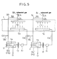
- a paint drying furnace as noted above has, acting as furnace interior heating means Hb, Hc for heating, to a high temperature, gases RA' returned from furnace interior circulating gas passages 9b, 9c to furnace interiors 1b, 1c, combustion type heating devices 19b', 19c' disposed on the furnace interior circulating gas passages 9b, 9c for heating gases RA circulating through the furnace interior circulating gas passages 9b, 9c by burning operation of burners b.
- combustion type heating devices 19b', 19c' for the furnace interiors it is necessary to employ indirect heating type, combustion type heating devices in which burning flames and combustion gas G produced by the burning operation of burners b and the gases RA circulating through the furnace interior circulating gas passages 9b, 9c to be heated exchange heat in a non-contact mode through inner heat exchangers hx.
- combustion type heating devices are employed as the combustion type heating devices 19b', 19c' for the furnace interiors, which burn a fuel directly in the atmosphere of gases RA circulating through the furnace interior circulating gas passages 9b, 9c, paint solvent vapor generated in the furnace interiors 1b, 1c during a baking and drying process and included in the gases RA circulating through the furnace interior circulating gas passages 9b, 9c is directly exposed and reacts to the burning flames in the combustion type heating devices 19b', 19c', to produce a reaction product which lowers paint film quality (i.e. a reaction product which adheres to the paint films after return to the furnace interiors 1b, 1c to lower paint film quality).
- the above construction is employed in order to prevent formation of such a reaction product.
- 8b, 8c denote furnace interior exhaust passages for discharging as exhaust gas EA from the system, part of furnace interior gases ZA withdrawn from the furnace interiors 1b, 1c.
- 18b', 18c' denote fresh air passages for mixing fresh air OA (usually ambient air) in a quantity corresponding to the exhaust gas from the furnace interior exhaust gas passages 8b, 8c into the gases RA circulating through the furnace interior circulating gas passages 9b, 9c to dilute the solvent vapor produced in the furnace interiors 1b, 1c.
- the above conventional furnace discharges from the system the combustion gas G retaining a large amount of heat after the heat exchange in the indirect heating type, combustion type heating devices 19b', 19c' with the gases RA circulating through the furnace interior circulating gas passages 9b, 9c (specifically, the circulating gases mixed with fresh air OA), and thus involves a great heat loss.
- the indirect heating type, combustion type heating devices 19b', 19c' including the inner heat exchangers hx have a large heat capacity, and require a large heating load in start-up times. These points pose a problem of high running cost.
- indirect heating type, combustion type heating devices 19b', 19c', with the inner heat exchangers hx have a large, complicated construction, which poses a problem of requiring high apparatus cost and large installation space.
- a primary object of this invention is to reduce the heat loss noted above while preventing formation of a reaction product which lowers paint film quality.
- Another object is to reduce the heating load in start-up times, and yet to downsize and simplify the apparatus construction.
- a paint drying furnace of this invention is a paint drying furnace noted in the outset hereof and characterized in that: said furnace interior heating means are combustion type heating devices arranged on said fresh air passages upstream of points of connection to said furnace interior circulating gas passages for heating passing fresh air, and these combustion type heating devices are direct heating type, combustion type heating devices for burning a fuel directly in an atmosphere of passing fresh air to be heated.
- combustion type heating devices are used as the furnace interior heating means for heating, to a high temperature, the gases to be returned from the furnace interior circulating gas passages to the furnace interiors, what is passed through these direct heating type, combustion type heating devices to be heated is fresh air containing no paint solvent vapor yet.
- the gases circulating through the furnace interior circulating gas passages and containing paint solvent vapor are not passed through the direct heating type, combustion type heating devices. This reliably avoids the problem of the paint solvent vapor being directly exposed and reacting to burning flames in the direct heating type, combustion type heating devices to produce a reaction product which lowers of paint film quality.
- the combustion gas generated in the direct heating type, combustion type heating devices is mixed with fresh air and then mixed into the gases circulating through the furnace interior circulating gas passages to contribute to heating of the furnace interiors.
- the direct heating type, combustion type heating devices require no inner heat exchangers for allowing a heat exchange in non-contact mode between burning flames and combustion gas, and the gases to be heated. These devices have a smaller heat capacity and impose a less heating load in start-up times than the indirect heating type, combustion type heating devices.
- the paint drying furnace of this invention can reduce running cost markedly, compared with the conventional furnace, described hereinbefore, having the indirect heating type, combustion type heating devices arranged on the furnace interior circulating gas passages to act as the furnace interior heating means.
- the apparatus since the direct heating type, combustion type heating devices require no inner heat exchangers, as noted above, the apparatus has a simple construction, compared with the indirect heating type, combustion type heating devices. Thus, compared with the conventional furnace, the apparatus cost may be reduced and the required installation space may be diminished.
- This invention may be embodied as follows.
- a combustion type exhaust cleaning device is provided for burning paint solvent vapor contained in exhaust gases from the furnace interiors to clean the exhaust gases, and a heat recovering heat exchanger is provided for allowing a heat exchange between the exhaust gases cleaned by this exhaust cleaning device and the fresh air to preheats the fresh air.
- Said fresh air passages are air passages for leading the fresh air preheated at said heat recovering heat exchanger to said furnace interior circulating gas passages through said combustion type heating devices.
- the direct heating type, combustion type heating devices disposed on the fresh air passages are operated to burn a fuel in the atmosphere of preheated fresh air. This improves the combustion efficiency of the combustion type heating devices to promote a reduction in the running cost more effectively, compared with a mode of introducing fresh air, without being preheated, into the direct heating type, combustion type heating devices.
- Fig. 1, 1 denotes a paint drying furnace for baking and drying paint films on painted objects 2 (which are automobile bodies in this example) following a painting process.
- the painted objects 2 mounted on carts 3a are transported by a conveyor apparatus 3 successively through a temperature increasing zone 1a, a first heat retaining zone 1b and a second heat retaining zone 1c in the furnace.
- the respective zones 1a, 1b, 1c in the furnace have gas supply chambers 5a, 5b, 5c defining a plurality of hot gas supply openings 4, and exhaust openings 6a, 6b, 6c for withdrawing zone interior gases ZA.
- the temperature increasing zone 1a has, in addition to the gas supply chamber 5a and exhaust opening 6a, radiator panels 7 for radiating heat to the painted objects 2.
- the zone interior gases ZA withdrawn through the exhaust openings 6a, 6b, 6c are divided into parts to be led as zone exhaust gases EA to furnace interior exhaust gas passages 8a, 8b, 8c assigned to the respective zones, and parts to be led as zone circulating gases RA to furnace interior circulating gas passages 9a, 9b, 9c assigned to the respective zones.
- the exhaust gases EA led to the furnace interior exhaust gas passages 8a, 8b, 8c are collected into an exhaust gas collection passage 10, and transmitted through a main exhaust gas passage 11 to a combustion type exhaust cleaning device 12.
- Fe denotes an exhaust fan.
- the exhaust cleaning device 12 includes a burner b and catalyst layers s. This exhaust cleaning device 12 cleans the exhaust gas EA by burning paint solvent vapor (i.e. paint solvent vapor generating from paint films as a result of a baking and drying process in the furnace) contained in the exhaust gas EA under catalysis. Cleaned exhaust gas EA' is outputted to an exhaust gas discharge passage 13.
- paint solvent vapor i.e. paint solvent vapor generating from paint films as a result of a baking and drying process in the furnace
- the 15 denotes a heat recovering heat exchanger at a cold side for allowing a heat exchange between fresh air OA (which is ambient air drawn from outside in this example) introduced through a main fresh air passage 16 and the cleaned exhaust gas EA' in the exhaust gas discharge passage 13 after passing through the heat recovering heat exchanger 14 at the hot side, thereby to preheat the fresh air OA.
- the cleaned exhaust gas EA' after being used for preheating the fresh air OA in the heat recovering heat exchanger 15 at the cold side is discharged from the system through the exhaust gas discharge passage 13.
- Each furnace interior circulating gas passage 9a, 9b, 9c has a downstream end thereof connected to the gas supply chamber 5a, 5b, 5c of the corresponding zone, and a filter 17 for cleaning circulating gas RA and a fan Fr for causing the circulation mounted in intermediate positions thereof.
- Individual fresh air passages 18a, 18b, 18c for the respective zones 1a, 1b, 1c are branched from the main fresh air passage 16. Each of these fresh air passages 18a, 18b, 18c has a fan Fo mounted thereon for drawing the fresh air. Of these fresh air passages 18a, 18b, 18c, the fresh air passages 18b, 18c for the first and second heat retaining zones 1b, 1c are connected to the furnace interior circulating gas passages 9b, 9c of the corresponding zones.
- the fresh air passages 18b, 18c for the first and second heat retaining zones 1b, 1c have, acting as furnace interior heating means Hb, Hc for the respective heat retaining zones 1b, 1c, combustion type furnace interior heating devices 19b, 19c arranged upstream of points of passage connection to the furnace interior circulating gas passages 9b, 9c for heating passing fresh air OA by burning operation of burners b.
- the combustion type furnace interior heating devices 19b, 19c employed are the direct heating type for burning a fuel directly in the atmosphere of fresh air OA flowing through the fresh air passages 18b, 18c.
- hot fresh air OA' (in particular, air containing combustion gas) heated by the combustion type furnace interior heating devices 19b, 19c is mixed into the gases RA circulating through the furnace interior circulating gas passages 9b, 9c, thereby heating, to a high temperature, the gases RA' returning to the heat retaining zones 1b, 1c from the furnace interior circulating gas passages 9b, 9c (i.e., gas mixtures of the zone circulating gas RA and hot fresh air OA').
- the gases RA' heated to a high temperature are delivered as hot gases from the hot gas supply openings 4 of gas supply chambers 5b, 5c into the heat retaining zones to heat the heat retaining zones by convection, thereby to adjust the interior temperatures of the respective heat retaining zones 1b, 1c to a predetermined temperature and to dilute the solvent vapor generated in the respective heat retaining zones 1b, 1c.
- radiator panels of the hot gas heat source type are employed as radiator panels 7, in which radiating surfaces 7a are heated by passing a heat source hot gas through inner gas passages ip to radiate heat from the radiating surfaces 7a to the painted objects 2.
- a radiator circulating gas passage 20 is provided to return gas PA outputted from the inner gas passages ip of the radiator panels 7, to the inner gas passages ip of the radiator panels 7.
- a combustion type radiator heating device 19a is mounted on the radiator circulating gas passage 20 for heating the gas PA circulating through the radiator circulating gas passage 20 by burning operation of a burner b.
- the combustion type radiator heating device 19a employed is the direct heating type, as are the combustion type furnace interior heating devices 19b, 19c for the first and second heat retaining zones 1b, 1c, for burning a fuel directly in the atmosphere of gas PA circulating through the radiator circulating gas passage 20.
- a shunt gas passage 21 is branched from a gas passage portion of the radiator circulating gas passage 20 which leads the gas PA outputted from the inner gas passages ip of radiator panels 7 to the combustion type radiator heating device 19a.
- the shunt gas passage 21 is connected to the furnace interior circulating gas passage 9a of the temperature increasing zone 1a.
- the fresh air passage 18a for the temperature increasing zone 1a is connected to the radiator circulating gas passage 20 in a position closer to the combustion type radiator heating device 19a than a branching position of the shunt gas passage 21.
- Fp denotes a circulating fan mounted in the radiator circulating gas passage 20.
- the combustion type radiator heating device 19a heats a gas mixture of the remainder of the gas PA outputted from the radiator panels 7, after part thereof is branched off into the shunt gas passage 21, and the fresh air OA supplied through the fresh air passage 18a.
- the heated gas PA' (in particular, a gas containing combustion gas) is passed through the inner gas passages ip of radiator panels 7 to radiate heat from the radiating surfaces 7a of radiator panels 7 to the painted objects 2.
- the hot gas PA branched off into the shunt gas passage 21 is mixed into the gas RA circulating through the furnace interior circulating gas passage 9a of the temperature increasing zone 1a to heat, to a high temperature, the gas RA' (i.e. a gas mixture of zone circulating gas RA of the temperature increasing zone 1a and hot gas PA'' supplied from the shunt gas passage 21) returned from the furnace interior circulating gas passage 9a to the temperature increasing zone 1a.
- the gas RA' heated to a high temperature is delivered as hot gas from the hot gas supply openings 4 of gas supply chamber 5a into the temperature increasing zone to heat the temperature increasing zone by convection, thereby to adjust the interior temperature of the temperature increasing zone 1a to a predetermined temperature.
- the gas mixture is introduced from the shunt gas passage 21 as a fresh gas into the temperature increasing zone 1a to dilute the solvent vapor generated therein.
- zone heating of the temperature increasing zone 1a is done by employing a mode in which the gas RA' returned from the furnace interior circulating gas passage 9a to the furnace interior 1a is heated to a high temperature by dividing and supplying the hot gas PA'' by the shunt gas passage 21 from the radiator circulating gas passage 20 to the furnace interior circulating gas passage 9a as noted above.
- the combustion type radiator heating device 19a on the radiator circulating gas passage 20 is made to serve also as furnace interior heating means Ha for the temperature increasing zone.
- furnace interior heating mode is employed in which the heated fresh air OA' is mixed into the gases RA circulating through the furnace interior circulating gas passages 9b, 9c to heat the zone interiors.
- a furnace interior heating mode is employed in which part of the hot clean gas PA in the radiator circulating gas passage 20 containing no paint solvent vapor is divided, and the divided hot clean gas PA'' is mixed into the gas RA circulating through the furnace interior circulating gas passage 9a to heat the furnace interior.
- the paint solvent vapor contained in the gases RA circulating through the furnace interior circulating gas passages 9a, 9b, 9c is exposed and reacts to burning flame in the direct heating type, combustion type heating devices, to produce a reaction product which would lower paint film quality. It is possible to avoid a situation where the reaction product mixes into the gases returning to the furnace interiors from the furnace interior circulating gas passages 9a, 9b, 9c.
- hoods 22a, 22b are arranged at the inlet and outlet of the furnace, respectively, for collecting furnace interior gases ZA' leaking out through the inlet and outlet.
- Hood exhaust gas passages 23a, 23b connected to these hoods 22a, 22b include hood gas exhaust fans Ff and gas passage opening and shutting dampers Df.
- the exhaust gas collection passage 10 is connected to the hood exhaust gas passages 23a, 23b in positions closer to the hoods than the gas passage opening and shutting dampers Df.
- gas passage opening and shutting dampers De of the furnace interior exhaust gas passages 8a, 8b, 8c of the respective zones 1a, 1b, 1c are opened, and gas passage opening and shutting dampers Df of the hood exhaust gas passages 23a, 23b are closed. Consequently, exhaust gases EA from the respective zones 1a, 1b, 1c and gases ZA' collected by the hoods 22a, 22b are transmitted to the exhaust cleaning device 12, and the exhaust cleaning device 12 burns the paint solvent vapor contained in these exhaust gases EA and collected gases ZA'.
- the gas passage opening and shutting dampers De of the furnace interior exhaust gas passages 8a, 8b, 8c of the respective zones 1a, 1b, 1c are closed to stop the exhaust gases from the respective zones 1a, 1b, 1c, thereby to expedite start-up of the zone temperatures.
- the gas passage opening and shutting dampers Df of the hood exhaust gas passages 23a, 23b are opened, whereby the hood exhaust fans Ff cause the gases ZA' collected by the hoods 22a, 22b (i.e. gases not containing paint solvent vapor yet) to be discharged to a fixed discharge location through the hood exhaust gas passages 23a, 23b.
- 24a, 24b in the drawing denote panel heaters for preventing the paint solvent vapor in the furnace interior gases from condensing on ceilings adjacent the inlet and outlet of the furnace.
- panel heaters 24a, 24b By preventing condensation of the paint solvent vapor with theses panel heaters 24a, 24b, a situation is avoided where condensed paint solvent drips on the painted objects 2 to lower paint film quality. Moreover, this assures that paint solvent vapors adjacent the inlet and outlet of the furnace are promptly collected along with the furnace interior gases ZA' by the hoods 22a, 22b and transmitted to the exhaust cleaning device 12.
- the panel heaters 24a, 24b employed are the hot gas heat source type to pass heat source hot gases through inner gas passages ia, ib.
- part of the hot gas PA' transmitted through the radiator circulating gas passage 20 from the combustion type radiator heating device 19a to the radiator panels 7 is supplied as heat source hot gas to the inner gas passage ia of panel heater 24a.
- the gas having passed through the inner gas passage ia of panel heater 24a is joined to the gas PA outputted from the radiator panels 7.
- part of the hot gas RA' supplied to the gas supply chamber 5c in the second heat retaining zone 1c is supplied as heat source hot gas to the inner gas passage ib of panel heater 24b.
- the gas having passed through the inner gas passage ib of panel heater 24b is joined to the gas ZA withdrawn from the zone 1c through the exhaust opening 6c.
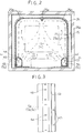
- Fig. 2 shows a specific inner structure of the first and second heat retaining zones 1b, 1c.
- a pair of gas supply chambers 5b, 5c extending in the direction of transport of the painted objects 2 are arranged at opposite, left and right ends in the zone bottom.
- Each of these gas supply chambers 5b, 5c defines, as the hot gas supply openings 4, upward supply openings 4a for blowing hot gas RA' upward along a furnace wall, and oblique supply openings 4b for blowing hot gas RA' obliquely upward toward the right and left center in the zone.
- these upward supply openings 4a and oblique supply openings 4b are arranged in respective rows in the direction of transport of the painted objects 2, with each opening in the form of a slit.
- Gas flow guides 25a, 25b extending in the direction of transport of the painted objects 2 are formed at the right and left center of the zone ceiling and at opposite, right and left ends of the zone ceiling for guiding zone interior gas flows as shown in arrows in the drawing.
- a furnace wall structure comprises a double wall structure including an outer wall panel 26 with an insulating material 26a applied thereto, and an inner wall panel 27 with an insulating material 27a applied thereto, an insulating layer of air 28 being formed between the inner and outer walls.
- each heat retaining zone 1a, 1b has one or two exhaust openings 6b, 6c opening at the right and left center of the zone ceiling.
- a specific inner structure of the temperature increasing zone 1a has a pair of gas supply chambers 5a extending in the direction of transport of the painted objects 2 and arranged at opposite, right and left ends of the zone bottom.
- Each of these gas supply chambers 5a defines upward supply openings 4a and oblique supply openings 4b as in the heat retaining zones 1b, 1c.
- the radiator panels 7 are arranged on opposite furnace walls above these gas supply chambers 5a.
- Gas flow guides 25a, 25b are provided as in the heat retaining zones 1b,1c.
- exhaust chambers are omitted as in the heat retaining zones 1b, 1c, and one or two exhaust openings 6a open at the right and left center of the zone ceiling. By omitting exhaust chambers in this way, large areas of the radiating surfaces 7a are secured for the radiator panel 7.
- the furnace wall in the temperature increasing zone 1a is formed only of a single wall panel 29 with an insulating material 29a applied thereto.
- a double wall structure as in the heat retaining zones 1b, 1c may be employed also for the temperature increasing zone 1a.
Landscapes
- Engineering & Computer Science (AREA)
- Mechanical Engineering (AREA)
- General Engineering & Computer Science (AREA)
- Life Sciences & Earth Sciences (AREA)
- Chemical & Material Sciences (AREA)
- Combustion & Propulsion (AREA)
- Microbiology (AREA)
- Sustainable Development (AREA)
- Drying Of Solid Materials (AREA)
- Coating Apparatus (AREA)
- Road Signs Or Road Markings (AREA)
Applications Claiming Priority (4)
| Application Number | Priority Date | Filing Date | Title |
|---|---|---|---|
| JP25602895 | 1995-10-03 | ||
| JP256028/95 | 1995-10-03 | ||
| JP25602895A JP3251157B2 (ja) | 1995-10-03 | 1995-10-03 | 塗装乾燥炉 |
| PCT/JP1996/002883 WO1997012690A1 (en) | 1995-10-03 | 1996-10-02 | Paint drying oven |
Publications (3)
| Publication Number | Publication Date |
|---|---|
| EP0803296A1 true EP0803296A1 (de) | 1997-10-29 |
| EP0803296A4 EP0803296A4 (de) | 1998-01-28 |
| EP0803296B1 EP0803296B1 (de) | 2000-03-22 |
Family
ID=17286921
Family Applications (1)
| Application Number | Title | Priority Date | Filing Date |
|---|---|---|---|
| EP96942980A Expired - Lifetime EP0803296B1 (de) | 1995-10-03 | 1996-10-02 | Lacktrocknungsofen |
Country Status (10)
| Country | Link |
|---|---|
| US (1) | US5868562A (de) |
| EP (1) | EP0803296B1 (de) |
| JP (1) | JP3251157B2 (de) |
| CN (1) | CN1079705C (de) |
| AT (1) | ATE190872T1 (de) |
| AU (1) | AU700889B2 (de) |
| CA (1) | CA2206642C (de) |
| DE (1) | DE69607319T2 (de) |
| ES (1) | ES2144797T3 (de) |
| WO (1) | WO1997012690A1 (de) |
Cited By (5)
| Publication number | Priority date | Publication date | Assignee | Title |
|---|---|---|---|---|
| EP0911086A1 (de) * | 1997-10-21 | 1999-04-28 | Dürr Systems GmbH | Kühlzone einer Lackieranlage und Verfahren zum Betreiben einer solchen Kühlzone |
| EP1076218A1 (de) * | 1999-08-11 | 2001-02-14 | EISENMANN MASCHINENBAU KG (Komplementär: EISENMANN-Stiftung) | Trockner für eine Lackieranlage |
| EP1790928A1 (de) * | 2005-11-25 | 2007-05-30 | Advanced Photonics Technologies AG | Bandbeschichtungsverfahren und Vorrichtung dafür |
| EP2360443A1 (de) * | 2009-12-30 | 2011-08-24 | Crone Wärmetechnik GmbH | Verfahren zum Trocknen von lackierten Trocknungsgütern, insbesondere Fahrzeugkarosserien |
| CN104607346B (zh) * | 2015-01-28 | 2016-12-07 | 杨巧霞 | 一种铝型材自动喷漆装置 |
Families Citing this family (21)
| Publication number | Priority date | Publication date | Assignee | Title |
|---|---|---|---|---|
| US6431859B1 (en) | 2001-01-12 | 2002-08-13 | North American Manufacturing Company | Combustion gas and air recovery apparatus |
| US6609907B1 (en) * | 2001-02-13 | 2003-08-26 | Entropy Technology And Environmental Consultants, Lp | Apparatus and method to control emissions of nitrogen oxide |
| DE10242944B4 (de) * | 2002-09-16 | 2005-07-07 | Eisenmann Maschinenbau Gmbh & Co. Kg | Trockner für Gegenstände, insbesondere für Fahrzeugkarosserien, sowie Verfahren zum Betreiben eines solchen Trockners |
| DE10349090A1 (de) * | 2003-10-22 | 2005-06-16 | Eisenmann Maschinenbau Gmbh & Co. Kg | Anlage und Verfahren zum Trocknen von Gegenständen |
| JP5196967B2 (ja) * | 2007-11-15 | 2013-05-15 | 株式会社大気社 | 塗装用乾燥方法及び塗装用乾燥装置 |
| DE102008012792B4 (de) * | 2008-03-05 | 2013-01-03 | Eisenmann Ag | Trockner für Lackieranlage |
| JP5457811B2 (ja) * | 2009-12-07 | 2014-04-02 | 富士フイルム株式会社 | 光学フィルムの製造方法 |
| DE102010001234A1 (de) * | 2010-01-26 | 2011-07-28 | Dürr Systems GmbH, 74321 | Anlage zum Trocknen von Karossen mit Gasturbine |
| DE102011119436B4 (de) * | 2011-11-25 | 2020-08-06 | Eisenmann Se | Vorrichtung zum Temperieren von Gegenständen |
| CN103575085B (zh) * | 2012-07-31 | 2016-04-20 | 苏州福斯特光伏材料有限公司 | 一种涂布机排放的有机废气燃烧处理及烘干加热联合装置 |
| US9810455B2 (en) * | 2013-01-30 | 2017-11-07 | Gasn Llc | Heat and energy recovery and regeneration assembly, system and method |
| CN103245185B (zh) * | 2013-05-27 | 2014-11-05 | 江苏骠马智能装备股份有限公司 | 混联型烘干加热系统 |
| DE102014015705A1 (de) * | 2014-10-22 | 2016-04-28 | Wenker Gmbh & Co. Kg | Trockner für technische Gegenstände, insbesondere für lackierte Kraftfahrzeugkarosserien |
| DE102015224916A1 (de) * | 2015-12-10 | 2017-06-14 | Dürr Systems Ag | Behandlungsanlage und Verfahren zum Behandeln von Werkstücken |
| CN105444536B (zh) * | 2015-12-18 | 2018-06-15 | 广东环葆嘉节能科技有限公司 | 一种串联式干燥系统 |
| DE102016001893A1 (de) | 2016-02-17 | 2017-08-17 | Eisenmann Se | Brennereinheit und Vorrichtung zum Temperieren von Gegenständen |
| US10982862B1 (en) | 2018-01-22 | 2021-04-20 | Commercial Energy Savings Plus, Llc | System and method for heat and energy recovery and regeneration |
| DE102018113685A1 (de) * | 2018-06-08 | 2018-08-23 | Eisenmann Se | Anlage zum Trocknen von Fahrzeugkarosserien |
| DE102020201705A1 (de) * | 2020-02-11 | 2021-08-12 | Dürr Systems Ag | Temperieranlage |
| CN113817908B (zh) * | 2021-08-13 | 2023-06-30 | 苏州新长光热能科技有限公司 | 一种退火炉 |
| JP7626804B1 (ja) | 2023-07-21 | 2025-02-04 | 株式会社大気社 | 熱風発生装置 |
Family Cites Families (27)
| Publication number | Priority date | Publication date | Assignee | Title |
|---|---|---|---|---|
| US3909953A (en) * | 1974-02-28 | 1975-10-07 | Midland Ross Corp | Paint drying method and apparatus |
| US4092100A (en) * | 1976-09-17 | 1978-05-30 | Granco Equipment, Inc. | Drying oven |
| US4116620A (en) * | 1977-05-23 | 1978-09-26 | Tec Systems, Inc. | Web drying apparatus having means for heating recirculated air |
| JPS556114A (en) * | 1978-06-26 | 1980-01-17 | Matsushita Electric Works Ltd | Method of setting flow of incoming air and outgoing air dryer |
| SE417639B (sv) * | 1979-08-09 | 1981-03-30 | Ake Evan Karlsson | Torkanleggning, serskilt for torkning av billacker eller herdning av plaster |
| US4255132A (en) * | 1979-09-12 | 1981-03-10 | Schweitzer Industrial Corp. | Incinerator-heater system |
| US4384850A (en) * | 1981-06-17 | 1983-05-24 | Tri-Mark Metal Corporation | Recirculating air heater |
| US4460331A (en) * | 1983-05-12 | 1984-07-17 | Haden Schweitzer Corporation | Fume incineration for paint drying oven |
| DE3326560A1 (de) * | 1983-07-22 | 1985-02-07 | LUTRO Luft- und Trockentechnik GmbH, 7022 Leinfelden-Echterdingen | Farbspritz- und/oder trockenkabine |
| GB2144988A (en) * | 1983-08-20 | 1985-03-20 | Metal Box Plc | Thermal treatment apparatus |
| IT1173156B (it) | 1984-01-27 | 1987-06-18 | Baruffaldi Frizioni Spa | Ponte a ruote direttrici particolarmente per veicoli per fuoristrada con semiassi collegati all'albero motore a mezzo di frizioni |
| JPS6150671A (ja) * | 1984-08-20 | 1986-03-12 | Mazda Motor Corp | 塗装用乾燥炉 |
| JPH0741200B2 (ja) * | 1984-11-27 | 1995-05-10 | 川崎製鉄株式会社 | 塗料の連続乾燥焼付装置の制御方法 |
| JPS61161173A (ja) * | 1985-01-11 | 1986-07-21 | Trinity Ind Corp | 塗装用乾燥炉及びその加熱方法 |
| JPS61174967A (ja) * | 1985-01-30 | 1986-08-06 | Toyota Motor Corp | 塗装乾燥炉 |
| JPS61185359A (ja) * | 1985-02-13 | 1986-08-19 | Toyota Motor Corp | 塗装用乾燥炉の加熱方法 |
| US4769925A (en) * | 1987-07-20 | 1988-09-13 | Taikisha Ltd. | Device for preventing resinous condensate dropping for use in paint drying oven |
| JP2525652B2 (ja) * | 1988-09-28 | 1996-08-21 | トリニティ工業株式会社 | 塗装品乾燥炉 |
| JP2721370B2 (ja) * | 1988-11-21 | 1998-03-04 | 川崎製鉄株式会社 | 塗料乾燥焼付炉の操業方法 |
| DE4023518A1 (de) * | 1990-07-24 | 1992-03-05 | Fritz Egger Gmbh | Verfahren und anlage zum trocknen von feuchtem gut |
| JP2527838B2 (ja) * | 1990-09-28 | 1996-08-28 | トリニティ工業株式会社 | 触媒燃焼装置を備えた焼付乾燥炉 |
| JPH0531435A (ja) * | 1991-07-31 | 1993-02-09 | Suzuki Motor Corp | 焼付乾燥炉 |
| JPH0556195A (ja) * | 1991-08-22 | 1993-03-05 | Nec Corp | 通話料金通知方式 |
| US5368157A (en) * | 1993-10-29 | 1994-11-29 | Baldwin Graphic Systems, Inc. | Pre-packaged, pre-soaked cleaning system and method for making the same |
| JP3173696B2 (ja) * | 1993-12-10 | 2001-06-04 | トリニティ工業株式会社 | 乾燥炉 |
| JPH08183A (ja) * | 1994-06-21 | 1996-01-09 | San Mekusu:Kk | 杜仲小枝材飼料添加剤 |
| JP6044589B2 (ja) | 2014-05-15 | 2016-12-14 | Jfeスチール株式会社 | 金属帯の圧延方法 |
-
1995
- 1995-10-03 JP JP25602895A patent/JP3251157B2/ja not_active Expired - Lifetime
-
1996
- 1996-10-02 AT AT96942980T patent/ATE190872T1/de not_active IP Right Cessation
- 1996-10-02 CN CN96191168A patent/CN1079705C/zh not_active Expired - Lifetime
- 1996-10-02 WO PCT/JP1996/002883 patent/WO1997012690A1/ja not_active Ceased
- 1996-10-02 DE DE69607319T patent/DE69607319T2/de not_active Expired - Lifetime
- 1996-10-02 AU AU11140/97A patent/AU700889B2/en not_active Expired
- 1996-10-02 EP EP96942980A patent/EP0803296B1/de not_active Expired - Lifetime
- 1996-10-02 ES ES96942980T patent/ES2144797T3/es not_active Expired - Lifetime
- 1996-10-02 CA CA002206642A patent/CA2206642C/en not_active Expired - Lifetime
- 1996-10-02 US US08/849,603 patent/US5868562A/en not_active Expired - Lifetime
Cited By (6)
| Publication number | Priority date | Publication date | Assignee | Title |
|---|---|---|---|---|
| EP0911086A1 (de) * | 1997-10-21 | 1999-04-28 | Dürr Systems GmbH | Kühlzone einer Lackieranlage und Verfahren zum Betreiben einer solchen Kühlzone |
| EP1076218A1 (de) * | 1999-08-11 | 2001-02-14 | EISENMANN MASCHINENBAU KG (Komplementär: EISENMANN-Stiftung) | Trockner für eine Lackieranlage |
| EP1790928A1 (de) * | 2005-11-25 | 2007-05-30 | Advanced Photonics Technologies AG | Bandbeschichtungsverfahren und Vorrichtung dafür |
| WO2007060009A1 (en) * | 2005-11-25 | 2007-05-31 | Advanced Photonics Technologies Ag | Coil coating process and apparatus |
| EP2360443A1 (de) * | 2009-12-30 | 2011-08-24 | Crone Wärmetechnik GmbH | Verfahren zum Trocknen von lackierten Trocknungsgütern, insbesondere Fahrzeugkarosserien |
| CN104607346B (zh) * | 2015-01-28 | 2016-12-07 | 杨巧霞 | 一种铝型材自动喷漆装置 |
Also Published As
| Publication number | Publication date |
|---|---|
| CA2206642C (en) | 2004-07-13 |
| ES2144797T3 (es) | 2000-06-16 |
| JP3251157B2 (ja) | 2002-01-28 |
| AU700889B2 (en) | 1999-01-14 |
| DE69607319T2 (de) | 2000-08-24 |
| JPH0994511A (ja) | 1997-04-08 |
| AU1114097A (en) | 1997-04-28 |
| DE69607319D1 (de) | 2000-04-27 |
| WO1997012690A1 (en) | 1997-04-10 |
| CN1168111A (zh) | 1997-12-17 |
| CA2206642A1 (en) | 1997-04-10 |
| EP0803296B1 (de) | 2000-03-22 |
| US5868562A (en) | 1999-02-09 |
| ATE190872T1 (de) | 2000-04-15 |
| EP0803296A4 (de) | 1998-01-28 |
| CN1079705C (zh) | 2002-02-27 |
Similar Documents
| Publication | Publication Date | Title |
|---|---|---|
| AU700889B2 (en) | Paint drying furnace | |
| US5823767A (en) | Paint drying furnace | |
| US4217090A (en) | Oven heating system | |
| US3706445A (en) | Fume incinerator | |
| US4989348A (en) | Continuous-flow dryer for material webs, in particular offset dryer process for the thermal operation of a continuous-flow dryer | |
| US5636622A (en) | Commercial gas oven for combined cooking | |
| JPH0236308B2 (de) | ||
| US4740158A (en) | Radiant energy drying oven with fume incineration feature | |
| EP0118535A1 (de) | Kombinierte ofen- und rauchverbrennungsvorrichtung und deren betrieb. | |
| US6412190B1 (en) | Infrared and hot air dryer combination | |
| US5345924A (en) | Cold spot baffle for coupling box | |
| US6889446B2 (en) | Drier for objects, particularly for vehicle bodies, and method for operating such a drier | |
| JPH07124513A (ja) | 塗料の連続焼付け乾燥装置 | |
| JPS582580A (ja) | 塗装オ−ブンにおける熱回収方法及び装置 | |
| JPH0732487U (ja) | Di缶ドライヤオーブン | |
| JPS5861868A (ja) | 塗装オ−ブンにおける熱投入方法及び装置 | |
| JPH01266878A (ja) | 塗装用乾燥炉 | |
| JPS607814Y2 (ja) | 塗装用焼付炉 | |
| JPS6197069A (ja) | 塗装用熱風乾燥炉 | |
| JP2521197Y2 (ja) | 熱風循環式焼付炉 | |
| JP3332528B2 (ja) | 直接加熱式塗装乾燥炉 | |
| RU1774134C (ru) | Устройство дл нагрева воздуха | |
| JPH07190620A (ja) | 塗装焼付乾燥炉への熱供給方法 | |
| JPS61161173A (ja) | 塗装用乾燥炉及びその加熱方法 | |
| JPH03217273A (ja) | 乾燥炉排ガス処理装置 |
Legal Events
| Date | Code | Title | Description |
|---|---|---|---|
| PUAI | Public reference made under article 153(3) epc to a published international application that has entered the european phase |
Free format text: ORIGINAL CODE: 0009012 |
|
| AK | Designated contracting states |
Kind code of ref document: A1 Designated state(s): AT BE DE DK ES FR GB NL PT SE |
|
| 17P | Request for examination filed |
Effective date: 19970923 |
|
| A4 | Supplementary search report drawn up and despatched | ||
| AK | Designated contracting states |
Kind code of ref document: A4 Designated state(s): AT BE DE DK ES FR GB NL PT SE |
|
| 17Q | First examination report despatched |
Effective date: 19980506 |
|
| GRAG | Despatch of communication of intention to grant |
Free format text: ORIGINAL CODE: EPIDOS AGRA |
|
| GRAG | Despatch of communication of intention to grant |
Free format text: ORIGINAL CODE: EPIDOS AGRA |
|
| GRAH | Despatch of communication of intention to grant a patent |
Free format text: ORIGINAL CODE: EPIDOS IGRA |
|
| GRAH | Despatch of communication of intention to grant a patent |
Free format text: ORIGINAL CODE: EPIDOS IGRA |
|
| GRAA | (expected) grant |
Free format text: ORIGINAL CODE: 0009210 |
|
| AK | Designated contracting states |
Kind code of ref document: B1 Designated state(s): AT BE DE DK ES FR GB NL PT SE |
|
| PG25 | Lapsed in a contracting state [announced via postgrant information from national office to epo] |
Ref country code: NL Free format text: LAPSE BECAUSE OF FAILURE TO SUBMIT A TRANSLATION OF THE DESCRIPTION OR TO PAY THE FEE WITHIN THE PRESCRIBED TIME-LIMIT Effective date: 20000322 Ref country code: BE Free format text: LAPSE BECAUSE OF FAILURE TO SUBMIT A TRANSLATION OF THE DESCRIPTION OR TO PAY THE FEE WITHIN THE PRESCRIBED TIME-LIMIT Effective date: 20000322 Ref country code: AT Free format text: LAPSE BECAUSE OF FAILURE TO SUBMIT A TRANSLATION OF THE DESCRIPTION OR TO PAY THE FEE WITHIN THE PRESCRIBED TIME-LIMIT Effective date: 20000322 |
|
| REF | Corresponds to: |
Ref document number: 190872 Country of ref document: AT Date of ref document: 20000415 Kind code of ref document: T |
|
| REF | Corresponds to: |
Ref document number: 69607319 Country of ref document: DE Date of ref document: 20000427 |
|
| ET | Fr: translation filed | ||
| REG | Reference to a national code |
Ref country code: ES Ref legal event code: FG2A Ref document number: 2144797 Country of ref document: ES Kind code of ref document: T3 |
|
| PG25 | Lapsed in a contracting state [announced via postgrant information from national office to epo] |
Ref country code: DK Free format text: LAPSE BECAUSE OF FAILURE TO SUBMIT A TRANSLATION OF THE DESCRIPTION OR TO PAY THE FEE WITHIN THE PRESCRIBED TIME-LIMIT Effective date: 20000622 |
|
| PG25 | Lapsed in a contracting state [announced via postgrant information from national office to epo] |
Ref country code: PT Free format text: LAPSE BECAUSE OF FAILURE TO SUBMIT A TRANSLATION OF THE DESCRIPTION OR TO PAY THE FEE WITHIN THE PRESCRIBED TIME-LIMIT Effective date: 20000623 |
|
| NLV1 | Nl: lapsed or annulled due to failure to fulfill the requirements of art. 29p and 29m of the patents act | ||
| PLBE | No opposition filed within time limit |
Free format text: ORIGINAL CODE: 0009261 |
|
| STAA | Information on the status of an ep patent application or granted ep patent |
Free format text: STATUS: NO OPPOSITION FILED WITHIN TIME LIMIT |
|
| 26N | No opposition filed | ||
| REG | Reference to a national code |
Ref country code: GB Ref legal event code: IF02 |
|
| PGFP | Annual fee paid to national office [announced via postgrant information from national office to epo] |
Ref country code: ES Payment date: 20141022 Year of fee payment: 19 Ref country code: SE Payment date: 20141022 Year of fee payment: 19 Ref country code: FR Payment date: 20141014 Year of fee payment: 19 Ref country code: GB Payment date: 20141007 Year of fee payment: 19 |
|
| PGFP | Annual fee paid to national office [announced via postgrant information from national office to epo] |
Ref country code: DE Payment date: 20141219 Year of fee payment: 19 |
|
| REG | Reference to a national code |
Ref country code: DE Ref legal event code: R119 Ref document number: 69607319 Country of ref document: DE |
|
| REG | Reference to a national code |
Ref country code: SE Ref legal event code: EUG |
|
| GBPC | Gb: european patent ceased through non-payment of renewal fee |
Effective date: 20151002 |
|
| PG25 | Lapsed in a contracting state [announced via postgrant information from national office to epo] |
Ref country code: DE Free format text: LAPSE BECAUSE OF NON-PAYMENT OF DUE FEES Effective date: 20160503 Ref country code: GB Free format text: LAPSE BECAUSE OF NON-PAYMENT OF DUE FEES Effective date: 20151002 |
|
| REG | Reference to a national code |
Ref country code: FR Ref legal event code: ST Effective date: 20160630 |
|
| PG25 | Lapsed in a contracting state [announced via postgrant information from national office to epo] |
Ref country code: FR Free format text: LAPSE BECAUSE OF NON-PAYMENT OF DUE FEES Effective date: 20151102 Ref country code: SE Free format text: LAPSE BECAUSE OF NON-PAYMENT OF DUE FEES Effective date: 20151003 |
|
| REG | Reference to a national code |
Ref country code: ES Ref legal event code: FD2A Effective date: 20161125 |
|
| PG25 | Lapsed in a contracting state [announced via postgrant information from national office to epo] |
Ref country code: ES Free format text: LAPSE BECAUSE OF NON-PAYMENT OF DUE FEES Effective date: 20151003 |