EP0803230A2 - Fil endovasculaire détachable de manière électrolytique pour former de thrombus - Google Patents
Fil endovasculaire détachable de manière électrolytique pour former de thrombus Download PDFInfo
- Publication number
- EP0803230A2 EP0803230A2 EP97112837A EP97112837A EP0803230A2 EP 0803230 A2 EP0803230 A2 EP 0803230A2 EP 97112837 A EP97112837 A EP 97112837A EP 97112837 A EP97112837 A EP 97112837A EP 0803230 A2 EP0803230 A2 EP 0803230A2
- Authority
- EP
- European Patent Office
- Prior art keywords
- wire
- microcatheter
- tip
- vascular cavity
- combination
- Prior art date
- Legal status (The legal status is an assumption and is not a legal conclusion. Google has not performed a legal analysis and makes no representation as to the accuracy of the status listed.)
- Granted
Links
- 208000007536 Thrombosis Diseases 0.000 title description 26
- 230000015572 biosynthetic process Effects 0.000 title description 14
- 230000002792 vascular Effects 0.000 claims abstract description 73
- 239000003550 marker Substances 0.000 claims abstract description 26
- BASFCYQUMIYNBI-UHFFFAOYSA-N platinum Chemical compound [Pt] BASFCYQUMIYNBI-UHFFFAOYSA-N 0.000 claims description 48
- 229910052697 platinum Inorganic materials 0.000 claims description 24
- 230000008878 coupling Effects 0.000 claims description 6
- 238000010168 coupling process Methods 0.000 claims description 6
- 238000005859 coupling reaction Methods 0.000 claims description 6
- 229920000728 polyester Polymers 0.000 claims description 5
- 206010002329 Aneurysm Diseases 0.000 description 58
- 229910001220 stainless steel Inorganic materials 0.000 description 29
- 239000010935 stainless steel Substances 0.000 description 25
- 238000000034 method Methods 0.000 description 19
- 210000004369 blood Anatomy 0.000 description 18
- 239000008280 blood Substances 0.000 description 18
- 210000001367 artery Anatomy 0.000 description 13
- 238000005755 formation reaction Methods 0.000 description 13
- 210000004209 hair Anatomy 0.000 description 10
- 238000011282 treatment Methods 0.000 description 10
- 201000008450 Intracranial aneurysm Diseases 0.000 description 8
- 238000001356 surgical procedure Methods 0.000 description 7
- 238000013459 approach Methods 0.000 description 6
- 230000010102 embolization Effects 0.000 description 6
- 238000000926 separation method Methods 0.000 description 6
- 230000017531 blood circulation Effects 0.000 description 5
- 238000005868 electrolysis reaction Methods 0.000 description 5
- 230000033001 locomotion Effects 0.000 description 5
- 206010003226 Arteriovenous fistula Diseases 0.000 description 4
- 239000004809 Teflon Substances 0.000 description 4
- 229920006362 Teflon® Polymers 0.000 description 4
- 239000000853 adhesive Substances 0.000 description 4
- 230000001070 adhesive effect Effects 0.000 description 4
- 239000000835 fiber Substances 0.000 description 4
- 238000002347 injection Methods 0.000 description 4
- 239000007924 injection Substances 0.000 description 4
- 238000003780 insertion Methods 0.000 description 4
- 230000037431 insertion Effects 0.000 description 4
- QRWOVIRDHQJFDB-UHFFFAOYSA-N isobutyl cyanoacrylate Chemical compound CC(C)COC(=O)C(=C)C#N QRWOVIRDHQJFDB-UHFFFAOYSA-N 0.000 description 4
- 230000002829 reductive effect Effects 0.000 description 4
- 102000008946 Fibrinogen Human genes 0.000 description 3
- 108010049003 Fibrinogen Proteins 0.000 description 3
- XEEYBQQBJWHFJM-UHFFFAOYSA-N Iron Chemical compound [Fe] XEEYBQQBJWHFJM-UHFFFAOYSA-N 0.000 description 3
- 208000009443 Vascular Malformations Diseases 0.000 description 3
- 210000001772 blood platelet Anatomy 0.000 description 3
- 230000015271 coagulation Effects 0.000 description 3
- 238000005345 coagulation Methods 0.000 description 3
- 239000011248 coating agent Substances 0.000 description 3
- 238000000576 coating method Methods 0.000 description 3
- 239000003814 drug Substances 0.000 description 3
- 210000003743 erythrocyte Anatomy 0.000 description 3
- 230000005294 ferromagnetic effect Effects 0.000 description 3
- 229940012952 fibrinogen Drugs 0.000 description 3
- 238000002594 fluoroscopy Methods 0.000 description 3
- 238000013467 fragmentation Methods 0.000 description 3
- 238000006062 fragmentation reaction Methods 0.000 description 3
- 210000000265 leukocyte Anatomy 0.000 description 3
- 239000007788 liquid Substances 0.000 description 3
- 239000013307 optical fiber Substances 0.000 description 3
- 238000012856 packing Methods 0.000 description 3
- 239000000523 sample Substances 0.000 description 3
- 210000003462 vein Anatomy 0.000 description 3
- 239000004831 Hot glue Substances 0.000 description 2
- 230000002776 aggregation Effects 0.000 description 2
- 238000004220 aggregation Methods 0.000 description 2
- 210000004556 brain Anatomy 0.000 description 2
- 238000002695 general anesthesia Methods 0.000 description 2
- 210000004013 groin Anatomy 0.000 description 2
- 201000002877 intracranial berry aneurysm Diseases 0.000 description 2
- 230000007246 mechanism Effects 0.000 description 2
- 239000000155 melt Substances 0.000 description 2
- 239000004005 microsphere Substances 0.000 description 2
- 239000000203 mixture Substances 0.000 description 2
- 230000003287 optical effect Effects 0.000 description 2
- 230000008569 process Effects 0.000 description 2
- 230000002787 reinforcement Effects 0.000 description 2
- 230000000717 retained effect Effects 0.000 description 2
- 229910000679 solder Inorganic materials 0.000 description 2
- 206010000060 Abdominal distension Diseases 0.000 description 1
- 206010053567 Coagulopathies Diseases 0.000 description 1
- RYGMFSIKBFXOCR-UHFFFAOYSA-N Copper Chemical compound [Cu] RYGMFSIKBFXOCR-UHFFFAOYSA-N 0.000 description 1
- 206010016717 Fistula Diseases 0.000 description 1
- 208000031238 Intracranial haemangioma Diseases 0.000 description 1
- 239000004698 Polyethylene Substances 0.000 description 1
- 229910001260 Pt alloy Inorganic materials 0.000 description 1
- 208000004717 Ruptured Aneurysm Diseases 0.000 description 1
- 208000005392 Spasm Diseases 0.000 description 1
- 229910000831 Steel Inorganic materials 0.000 description 1
- 206010047163 Vasospasm Diseases 0.000 description 1
- 230000009471 action Effects 0.000 description 1
- 229910045601 alloy Inorganic materials 0.000 description 1
- 239000000956 alloy Substances 0.000 description 1
- 230000004075 alteration Effects 0.000 description 1
- 210000000576 arachnoid Anatomy 0.000 description 1
- 238000010420 art technique Methods 0.000 description 1
- 229910052790 beryllium Inorganic materials 0.000 description 1
- ATBAMAFKBVZNFJ-UHFFFAOYSA-N beryllium atom Chemical compound [Be] ATBAMAFKBVZNFJ-UHFFFAOYSA-N 0.000 description 1
- 230000023555 blood coagulation Effects 0.000 description 1
- 210000001627 cerebral artery Anatomy 0.000 description 1
- 230000002490 cerebral effect Effects 0.000 description 1
- 239000003795 chemical substances by application Substances 0.000 description 1
- 230000035602 clotting Effects 0.000 description 1
- 230000001112 coagulating effect Effects 0.000 description 1
- 150000001875 compounds Chemical class 0.000 description 1
- 239000004020 conductor Substances 0.000 description 1
- 239000000470 constituent Substances 0.000 description 1
- 229910052802 copper Inorganic materials 0.000 description 1
- 239000010949 copper Substances 0.000 description 1
- 238000007428 craniotomy Methods 0.000 description 1
- 230000003247 decreasing effect Effects 0.000 description 1
- 230000007547 defect Effects 0.000 description 1
- 230000003111 delayed effect Effects 0.000 description 1
- 238000004925 denaturation Methods 0.000 description 1
- 230000036425 denaturation Effects 0.000 description 1
- 201000010099 disease Diseases 0.000 description 1
- 208000037265 diseases, disorders, signs and symptoms Diseases 0.000 description 1
- 238000006073 displacement reaction Methods 0.000 description 1
- 238000002224 dissection Methods 0.000 description 1
- 238000009826 distribution Methods 0.000 description 1
- 230000000694 effects Effects 0.000 description 1
- 238000002474 experimental method Methods 0.000 description 1
- 230000003890 fistula Effects 0.000 description 1
- 238000007429 general method Methods 0.000 description 1
- PCHJSUWPFVWCPO-UHFFFAOYSA-N gold Chemical compound [Au] PCHJSUWPFVWCPO-UHFFFAOYSA-N 0.000 description 1
- 229910052737 gold Inorganic materials 0.000 description 1
- 239000010931 gold Substances 0.000 description 1
- 230000006872 improvement Effects 0.000 description 1
- 238000007917 intracranial administration Methods 0.000 description 1
- 230000009545 invasion Effects 0.000 description 1
- 229910052742 iron Inorganic materials 0.000 description 1
- 230000001788 irregular Effects 0.000 description 1
- 238000003475 lamination Methods 0.000 description 1
- 230000000670 limiting effect Effects 0.000 description 1
- 238000002690 local anesthesia Methods 0.000 description 1
- 230000005291 magnetic effect Effects 0.000 description 1
- 238000012423 maintenance Methods 0.000 description 1
- 125000002496 methyl group Chemical group [H]C([H])([H])* 0.000 description 1
- 238000002406 microsurgery Methods 0.000 description 1
- 238000012986 modification Methods 0.000 description 1
- 230000004048 modification Effects 0.000 description 1
- 230000036961 partial effect Effects 0.000 description 1
- 239000002245 particle Substances 0.000 description 1
- -1 polyethylene Polymers 0.000 description 1
- 229920000573 polyethylene Polymers 0.000 description 1
- 230000000379 polymerizing effect Effects 0.000 description 1
- 238000004321 preservation Methods 0.000 description 1
- 230000001681 protective effect Effects 0.000 description 1
- 102000004169 proteins and genes Human genes 0.000 description 1
- 108090000623 proteins and genes Proteins 0.000 description 1
- 230000000246 remedial effect Effects 0.000 description 1
- 210000004761 scalp Anatomy 0.000 description 1
- 239000007787 solid Substances 0.000 description 1
- 239000010959 steel Substances 0.000 description 1
- 239000000725 suspension Substances 0.000 description 1
- 230000001732 thrombotic effect Effects 0.000 description 1
- 231100000331 toxic Toxicity 0.000 description 1
- 230000002588 toxic effect Effects 0.000 description 1
- 230000000007 visual effect Effects 0.000 description 1
Images


Classifications
-
- A—HUMAN NECESSITIES
- A61—MEDICAL OR VETERINARY SCIENCE; HYGIENE
- A61M—DEVICES FOR INTRODUCING MEDIA INTO, OR ONTO, THE BODY; DEVICES FOR TRANSDUCING BODY MEDIA OR FOR TAKING MEDIA FROM THE BODY; DEVICES FOR PRODUCING OR ENDING SLEEP OR STUPOR
- A61M25/00—Catheters; Hollow probes
- A61M25/01—Introducing, guiding, advancing, emplacing or holding catheters
- A61M25/09—Guide wires
-
- A—HUMAN NECESSITIES
- A61—MEDICAL OR VETERINARY SCIENCE; HYGIENE
- A61B—DIAGNOSIS; SURGERY; IDENTIFICATION
- A61B17/00—Surgical instruments, devices or methods
- A61B17/12—Surgical instruments, devices or methods for ligaturing or otherwise compressing tubular parts of the body, e.g. blood vessels or umbilical cord
- A61B17/12022—Occluding by internal devices, e.g. balloons or releasable wires
- A61B17/12099—Occluding by internal devices, e.g. balloons or releasable wires characterised by the location of the occluder
- A61B17/12109—Occluding by internal devices, e.g. balloons or releasable wires characterised by the location of the occluder in a blood vessel
- A61B17/12113—Occluding by internal devices, e.g. balloons or releasable wires characterised by the location of the occluder in a blood vessel within an aneurysm
-
- A—HUMAN NECESSITIES
- A61—MEDICAL OR VETERINARY SCIENCE; HYGIENE
- A61B—DIAGNOSIS; SURGERY; IDENTIFICATION
- A61B17/00—Surgical instruments, devices or methods
- A61B17/12—Surgical instruments, devices or methods for ligaturing or otherwise compressing tubular parts of the body, e.g. blood vessels or umbilical cord
- A61B17/12022—Occluding by internal devices, e.g. balloons or releasable wires
- A61B17/12131—Occluding by internal devices, e.g. balloons or releasable wires characterised by the type of occluding device
- A61B17/1214—Coils or wires
- A61B17/12145—Coils or wires having a pre-set deployed three-dimensional shape
-
- A—HUMAN NECESSITIES
- A61—MEDICAL OR VETERINARY SCIENCE; HYGIENE
- A61B—DIAGNOSIS; SURGERY; IDENTIFICATION
- A61B17/00—Surgical instruments, devices or methods
- A61B17/12—Surgical instruments, devices or methods for ligaturing or otherwise compressing tubular parts of the body, e.g. blood vessels or umbilical cord
- A61B17/12022—Occluding by internal devices, e.g. balloons or releasable wires
- A61B17/12131—Occluding by internal devices, e.g. balloons or releasable wires characterised by the type of occluding device
- A61B17/1214—Coils or wires
- A61B17/1215—Coils or wires comprising additional materials, e.g. thrombogenic, having filaments, having fibers, being coated
-
- A—HUMAN NECESSITIES
- A61—MEDICAL OR VETERINARY SCIENCE; HYGIENE
- A61B—DIAGNOSIS; SURGERY; IDENTIFICATION
- A61B18/00—Surgical instruments, devices or methods for transferring non-mechanical forms of energy to or from the body
- A61B18/04—Surgical instruments, devices or methods for transferring non-mechanical forms of energy to or from the body by heating
- A61B18/12—Surgical instruments, devices or methods for transferring non-mechanical forms of energy to or from the body by heating by passing a current through the tissue to be heated, e.g. high-frequency current
- A61B18/14—Probes or electrodes therefor
- A61B18/1492—Probes or electrodes therefor having a flexible, catheter-like structure, e.g. for heart ablation
-
- A—HUMAN NECESSITIES
- A61—MEDICAL OR VETERINARY SCIENCE; HYGIENE
- A61B—DIAGNOSIS; SURGERY; IDENTIFICATION
- A61B17/00—Surgical instruments, devices or methods
- A61B17/00234—Surgical instruments, devices or methods for minimally invasive surgery
- A61B2017/00292—Surgical instruments, devices or methods for minimally invasive surgery mounted on or guided by flexible, e.g. catheter-like, means
-
- A—HUMAN NECESSITIES
- A61—MEDICAL OR VETERINARY SCIENCE; HYGIENE
- A61B—DIAGNOSIS; SURGERY; IDENTIFICATION
- A61B17/00—Surgical instruments, devices or methods
- A61B17/12—Surgical instruments, devices or methods for ligaturing or otherwise compressing tubular parts of the body, e.g. blood vessels or umbilical cord
- A61B17/12022—Occluding by internal devices, e.g. balloons or releasable wires
- A61B2017/1205—Introduction devices
- A61B2017/12054—Details concerning the detachment of the occluding device from the introduction device
- A61B2017/12063—Details concerning the detachment of the occluding device from the introduction device electrolytically detachable
-
- A—HUMAN NECESSITIES
- A61—MEDICAL OR VETERINARY SCIENCE; HYGIENE
- A61B—DIAGNOSIS; SURGERY; IDENTIFICATION
- A61B17/00—Surgical instruments, devices or methods
- A61B17/12—Surgical instruments, devices or methods for ligaturing or otherwise compressing tubular parts of the body, e.g. blood vessels or umbilical cord
- A61B17/12022—Occluding by internal devices, e.g. balloons or releasable wires
- A61B2017/1205—Introduction devices
- A61B2017/12054—Details concerning the detachment of the occluding device from the introduction device
- A61B2017/12095—Threaded connection
-
- A—HUMAN NECESSITIES
- A61—MEDICAL OR VETERINARY SCIENCE; HYGIENE
- A61B—DIAGNOSIS; SURGERY; IDENTIFICATION
- A61B17/00—Surgical instruments, devices or methods
- A61B17/22—Implements for squeezing-off ulcers or the like on inner organs of the body; Implements for scraping-out cavities of body organs, e.g. bones; for invasive removal or destruction of calculus using mechanical vibrations; for removing obstructions in blood vessels, not otherwise provided for
- A61B2017/22038—Implements for squeezing-off ulcers or the like on inner organs of the body; Implements for scraping-out cavities of body organs, e.g. bones; for invasive removal or destruction of calculus using mechanical vibrations; for removing obstructions in blood vessels, not otherwise provided for with a guide wire
-
- A—HUMAN NECESSITIES
- A61—MEDICAL OR VETERINARY SCIENCE; HYGIENE
- A61B—DIAGNOSIS; SURGERY; IDENTIFICATION
- A61B18/00—Surgical instruments, devices or methods for transferring non-mechanical forms of energy to or from the body
- A61B2018/00636—Sensing and controlling the application of energy
- A61B2018/00666—Sensing and controlling the application of energy using a threshold value
- A61B2018/00678—Sensing and controlling the application of energy using a threshold value upper
-
- A—HUMAN NECESSITIES
- A61—MEDICAL OR VETERINARY SCIENCE; HYGIENE
- A61B—DIAGNOSIS; SURGERY; IDENTIFICATION
- A61B18/00—Surgical instruments, devices or methods for transferring non-mechanical forms of energy to or from the body
- A61B2018/00636—Sensing and controlling the application of energy
- A61B2018/00696—Controlled or regulated parameters
- A61B2018/00761—Duration
-
- A—HUMAN NECESSITIES
- A61—MEDICAL OR VETERINARY SCIENCE; HYGIENE
- A61B—DIAGNOSIS; SURGERY; IDENTIFICATION
- A61B18/00—Surgical instruments, devices or methods for transferring non-mechanical forms of energy to or from the body
- A61B2018/00636—Sensing and controlling the application of energy
- A61B2018/00773—Sensed parameters
- A61B2018/00875—Resistance or impedance
-
- A—HUMAN NECESSITIES
- A61—MEDICAL OR VETERINARY SCIENCE; HYGIENE
- A61B—DIAGNOSIS; SURGERY; IDENTIFICATION
- A61B18/00—Surgical instruments, devices or methods for transferring non-mechanical forms of energy to or from the body
- A61B2018/00636—Sensing and controlling the application of energy
- A61B2018/00773—Sensed parameters
- A61B2018/00886—Duration
-
- A—HUMAN NECESSITIES
- A61—MEDICAL OR VETERINARY SCIENCE; HYGIENE
- A61B—DIAGNOSIS; SURGERY; IDENTIFICATION
- A61B18/00—Surgical instruments, devices or methods for transferring non-mechanical forms of energy to or from the body
- A61B18/04—Surgical instruments, devices or methods for transferring non-mechanical forms of energy to or from the body by heating
- A61B18/12—Surgical instruments, devices or methods for transferring non-mechanical forms of energy to or from the body by heating by passing a current through the tissue to be heated, e.g. high-frequency current
- A61B18/1206—Generators therefor
- A61B2018/1226—Generators therefor powered by a battery
-
- A—HUMAN NECESSITIES
- A61—MEDICAL OR VETERINARY SCIENCE; HYGIENE
- A61B—DIAGNOSIS; SURGERY; IDENTIFICATION
- A61B18/00—Surgical instruments, devices or methods for transferring non-mechanical forms of energy to or from the body
- A61B18/04—Surgical instruments, devices or methods for transferring non-mechanical forms of energy to or from the body by heating
- A61B18/12—Surgical instruments, devices or methods for transferring non-mechanical forms of energy to or from the body by heating by passing a current through the tissue to be heated, e.g. high-frequency current
- A61B18/1206—Generators therefor
- A61B2018/1246—Generators therefor characterised by the output polarity
- A61B2018/1253—Generators therefor characterised by the output polarity monopolar
-
- A—HUMAN NECESSITIES
- A61—MEDICAL OR VETERINARY SCIENCE; HYGIENE
- A61B—DIAGNOSIS; SURGERY; IDENTIFICATION
- A61B18/00—Surgical instruments, devices or methods for transferring non-mechanical forms of energy to or from the body
- A61B18/04—Surgical instruments, devices or methods for transferring non-mechanical forms of energy to or from the body by heating
- A61B18/12—Surgical instruments, devices or methods for transferring non-mechanical forms of energy to or from the body by heating by passing a current through the tissue to be heated, e.g. high-frequency current
- A61B18/1206—Generators therefor
- A61B2018/1246—Generators therefor characterised by the output polarity
- A61B2018/126—Generators therefor characterised by the output polarity bipolar
-
- A—HUMAN NECESSITIES
- A61—MEDICAL OR VETERINARY SCIENCE; HYGIENE
- A61B—DIAGNOSIS; SURGERY; IDENTIFICATION
- A61B18/00—Surgical instruments, devices or methods for transferring non-mechanical forms of energy to or from the body
- A61B18/04—Surgical instruments, devices or methods for transferring non-mechanical forms of energy to or from the body by heating
- A61B18/12—Surgical instruments, devices or methods for transferring non-mechanical forms of energy to or from the body by heating by passing a current through the tissue to be heated, e.g. high-frequency current
- A61B18/1206—Generators therefor
- A61B2018/1266—Generators therefor with DC current output
-
- A—HUMAN NECESSITIES
- A61—MEDICAL OR VETERINARY SCIENCE; HYGIENE
- A61B—DIAGNOSIS; SURGERY; IDENTIFICATION
- A61B18/00—Surgical instruments, devices or methods for transferring non-mechanical forms of energy to or from the body
- A61B18/04—Surgical instruments, devices or methods for transferring non-mechanical forms of energy to or from the body by heating
- A61B18/12—Surgical instruments, devices or methods for transferring non-mechanical forms of energy to or from the body by heating by passing a current through the tissue to be heated, e.g. high-frequency current
- A61B18/14—Probes or electrodes therefor
- A61B2018/1405—Electrodes having a specific shape
- A61B2018/1435—Spiral
-
- A—HUMAN NECESSITIES
- A61—MEDICAL OR VETERINARY SCIENCE; HYGIENE
- A61B—DIAGNOSIS; SURGERY; IDENTIFICATION
- A61B18/00—Surgical instruments, devices or methods for transferring non-mechanical forms of energy to or from the body
- A61B18/04—Surgical instruments, devices or methods for transferring non-mechanical forms of energy to or from the body by heating
- A61B18/12—Surgical instruments, devices or methods for transferring non-mechanical forms of energy to or from the body by heating by passing a current through the tissue to be heated, e.g. high-frequency current
- A61B18/14—Probes or electrodes therefor
- A61B2018/1495—Electrodes being detachable from a support structure
-
- A—HUMAN NECESSITIES
- A61—MEDICAL OR VETERINARY SCIENCE; HYGIENE
- A61B—DIAGNOSIS; SURGERY; IDENTIFICATION
- A61B90/00—Instruments, implements or accessories specially adapted for surgery or diagnosis and not covered by any of the groups A61B1/00 - A61B50/00, e.g. for luxation treatment or for protecting wound edges
- A61B90/39—Markers, e.g. radio-opaque or breast lesions markers
- A61B2090/3966—Radiopaque markers visible in an X-ray image
-
- A—HUMAN NECESSITIES
- A61—MEDICAL OR VETERINARY SCIENCE; HYGIENE
- A61B—DIAGNOSIS; SURGERY; IDENTIFICATION
- A61B90/00—Instruments, implements or accessories specially adapted for surgery or diagnosis and not covered by any of the groups A61B1/00 - A61B50/00, e.g. for luxation treatment or for protecting wound edges
- A61B90/39—Markers, e.g. radio-opaque or breast lesions markers
-
- A—HUMAN NECESSITIES
- A61—MEDICAL OR VETERINARY SCIENCE; HYGIENE
- A61M—DEVICES FOR INTRODUCING MEDIA INTO, OR ONTO, THE BODY; DEVICES FOR TRANSDUCING BODY MEDIA OR FOR TAKING MEDIA FROM THE BODY; DEVICES FOR PRODUCING OR ENDING SLEEP OR STUPOR
- A61M25/00—Catheters; Hollow probes
- A61M25/01—Introducing, guiding, advancing, emplacing or holding catheters
- A61M25/09—Guide wires
- A61M2025/09175—Guide wires having specific characteristics at the distal tip
Definitions
- the invention relates to a method and apparatus for endovascular electrothrombic formation of thrombi in arteries, veins, aneurysms, vascular malformations and arteriovenous fistulas.
- the extravascular approach is comprised of surgery or microsurgery of the aneurysm or treatment site for the purpose of preserving the parent artery.
- This treatment is common with intracranial berry aneurysms.
- the methodology comprises the step of clipping the neck of the aneurysm, performing a suture-ligation of the neck, or wrapping the entire aneurysm.
- Each of these surgical procedures is performed by intrusive invasion into the body and performed from outside the aneurysm or target site.
- General anesthesia, craniotomy, brain retraction and arachnoid dissection around the neck of the aneurysm and placement of a clip are typically required in these surgical procedures.
- Surgical treatment of vascular intracranial aneurysm can expect a mortality rate of 4-8% with a morbidity rate of 18-20%. Because of the mortality and morbidity rate expected, the surgical procedure is often delayed while waiting for the best surgical time with the result that an additional percentage of patients will die from the underlying disease or defect prior to surgery. For this reason the prior art has sought alternative means of treatment.
- microcatheters In the endovascular approach, the interior of the aneurysm is entered through the use of a microcatheter. Recently developed microcatheters, such as those shown by Engelson , "Catheter Guidewire” , U.S. Patent 4,884,579 and as described in Engelson , "Catheter for Guidewire Tracking” , U.S. Patent 4,739,768 (1988), allow navigation into the cerebral arteries and entry into a cranial aneurysm.
- a balloon is typically attached to the end of the microcatheter and it is possible to introduce the balloon into the aneurysm, inflate it, and detach it, leaving it to occlude the sac and neck with preservation of the parent artery.
- endovascular balloon embolization of berry aneurysms is an attractive method in situations where an extravascular surgical approach is difficult, inflation of a balloon into the aneurysm carries some risk of aneurysm rupture due to possible over-distention of portions of the sac and due to the traction produced while detaching the balloon.
- an ideal embolizing agent should adapt itself to the irregular shape of the internal walls of the aneurysm.
- the aneurysmal wall must conform to the shape of the balloon. This may not lead to a satisfactory result and further increases the risk of rupture.
- balloon embolization is not always possible. If the diameter of the deflated balloon is too great to enter the intracerebral arteries, especially in the cases where there is a vasospasm, complication with ruptured intracranial aneurysms may occur. The procedure then must be deferred until the spasm is resolved and this then incurs a risk of rebleeding.
- an aneurysm is surgically exposed or stereotaxically reached with a probe.
- the wall of the aneurysm is then perforated from the outside and various techniques are used to occlude the interior in order to prevent it from rebleeding.
- These prior art techniques include electrothrombosis, isobutyl-cyanoacrylate embolization, hog-hair embolization and ferromagnetic thrombosis.
- the tip of a positively charged electrode is inserted surgically into the interior of the aneurysm.
- An application of the positive charge attracts white blood cells, red blood cells, platelets and fibrinogen which are typically negatively charged at the normal pH of the blood.
- the thrombic mass is then formed in the aneurysm about the tip. Thereafter, the tip is removed. See Mullan , "Experiences with Surgical Thrombosis of Intracranial Berry Aneurysms and Carotid Cavernous Fistulas" , J. Neurosurg., Vol.
- the prior art has also devised the use of a liquid adhesive, isobutylcyanoacrylate (IBCA) which polymerizes rapidly on contact with blood to form a firm mass.
- IBCA isobutylcyanoacrylate
- the liquid adhesive is injected into the aneurysm by puncturing the sac with a small needle.
- blood flow through the parent artery must be momentarily reduced or interrupted.
- an inflated balloon may be placed in the artery at the level of the neck of the aneurysm for injection.
- the risks of seepage of such a polymerizing adhesive into the parent artery exists, if it is not completely blocked with consequent occlusion of the artery.
- the prior art has utilized an air gun to inject hog hair through the aneurysm wall to induce internal thrombosis.
- the success of this procedure involves exposing the aneurysm sufficiently to allow air gun injection and has not been convincingly shown as successful for thrombic formations.
- Ferromagnetic thrombosis in the prior art in extra-intravascular treatments comprises the stereotactic placement of a magnetic probe against the sac of the aneurysm followed by injection into the aneurysm by an injecting needle of iron microspheres. Aggregation of the microspheres through the extravascular magnet is followed by interneuysmatic thrombus. This treatment has not been entirely successful because of the risk of fragmentation of the metallic thrombus when the extravacular magnet is removed. Suspension of the iron powder in methyl methymethacrylate has been used to prevent fragmentation.
- the treatment has not been favored, because of the need to puncture the aneurysm, the risk of occlusion of the parent artery, the use of unusual and expensive equipment, the need for a craniectomy and general anesthesia, and the necessity to penetrate cerebral tissue to reach the aneurysm.
- Endovascular coagulation of blood is also well known in the art and a device using laser optically generated heat is shown by O'Reilly , "Optical Fiber with Attachable Metallic Tip for Intravascular Laser Coagulation of Arteries, Veins, Aneurysms, Vascular Malformation and Arteriovenous Fistulas" , U.S. Patent 4,735,201 (1988). See also, O'Reilly et al . , “Laser Induced Thermal Occlusion of Berry Aneurysms: Initial Experimental Results” , Radiology, Vol. 171, No. 2, pages 471-74 (1989). O'Reilly places a tip into an aneurysm by means of an endovascular microcatheter.
- the tip is adhesively bonded to a optic fiber disposed through the microcatheter.
- Optical energy is transmitted along the optic fiber from a remote laser at the proximal end of the microcatheter.
- the optical energy heats the tip to cauterize the tissue surrounding the neck of the aneurysm or other vascular opening to be occluded.
- the catheter is provided with a balloon located on or adjacent to its distal end to cut off blood flow to the site to be cauterized and occluded. Normally, the blood flow would carry away the heat at the catheter tip, thereby preventing cauterization.
- the heat in the tip also serves to melt the adhesive used to secure the tip to the distal end of the optical fiber. If all goes well, the tip can be separated from the optical fiber and left in place in the neck of the aneurysm, provided that the cauterization is complete at the same time as the hot melt adhesive melts.
- a thrombus is not formed from the heated tip. Instead, blood tissue surrounding the tip is coagulated. Coagulation is a denaturation of protein to form a connective-like tissue similar to that which occurs when the albumen of an egg is heated and coagulates from a clear running liquid to an opaque white solid. The tissue characteristics and composition of the coagulated tissue is therefore substantially distinct from the thrombosis which is formed by the thrombotic aggregation of white and red blood cells, platelets and fibrinogen. The coagulative tissue is substantially softer than a thrombic mass and can therefore more easily be dislodged.
- O'Reilly's device depends at least in part upon the successful cauterization timed to occur no later than the detachment of the heat tip from the optic fiber.
- the heated tip must also be proportionally sized to the neck of the aneurysm in order to effectively coagulate the tissue surrounding it to form a blockage at the neck. It is believed that the tissue in the interior of the aneurysm remains substantially uncoagulated.
- the hot melt adhesive attaching the tip to the optic fiber melts and is dispersed into the adjacent blood tissue where it resolidifies to form free particles within the intracranial blood stream with much the same disadvantages which result from fragmentation of a ferromagnetic electrothrombosis.
- the invention is a method for forming an occlusion with a vascular cavity having blood disposed therein comprising the steps of endovascularly disposing a wire and/or tip near an endovascular opening into the vascular cavity.
- the wire may include a distinguishable structure at its distal end, which is termed a tip, in which case the remaining portion of the wire may be termed a guidewire.
- the term "wire” should be understood to collectively include both guidewires and tips and simply wires without distinct tip structures. However, the tip may also simply be the extension of the wire itself without substantial distinction in its nature.
- a distal tip of the wire is disposed into the vascular cavity to pack the cavity to mechanically form the occlusion within the vascular cavity about the distal tip. The distal tip is detached from the guidewire (or wire) to leave the distal tip within the vascular cavity. As a result, the vascular cavity is occluded by the distal tip, and by any thrombus formed by use of the tip.
- the step of detaching the distal tip from the guidewire (or wire) comprises the step of mechanically detaching the distal tip from the guidewire (or wire).
- the guidewire and tip (or wire) are used within a microcatheter and in the step of detaching the distal tip from the guidewire (or wire), the guidewire and tip (or wire) are longitudinally displaced within the microcatheter.
- the microcatheter has radio-opaque proximal and tip markers.
- the guidewire and tip (or wire) have collectively a single radio-opaque marker.
- the displacement of the guidewire and tip (or wire) moves the single radio-opaque marker to the proximity of the proximal marker on the microcatheter. At this point the tip will be fully deployed in the vascular cavity and tip separation may proceed. It is not necessary then in this embodiment to be able to see actual deployment of the tip before separation.
- the tip marker allows and enhances direct observation of the correct placement of the catheter tip into the opening of the vascular cavity.
- the step of disposing the tip (or wire) into the vascular cavity to pack the cavity comprises the step of disposing a tip (or wire) having a plurality of filaments extending therefrom to pack the cavity.
- the step of disposing the tip (or wire) into the vascular cavity to pack the cavity comprises the step of disposing a long flexible tip (or wire) folded upon itself a multiple number of times to pack the cavity.
- the invention can also be characterized as a method for forming an occlusion within a vascular cavity having blood disposed therein comprising the steps of endovascularly disposing a wire within a microcatheter near an endovascular opening into the vascular cavity.
- the microcatheter has a distal tip electrode.
- the distal tip of the wire is disposed into the vascular cavity to pack the cavity to form the occlusion within the vascular cavity about the distal tip of the wire by applying a current between the distal tip electrode and the distal end of the wire packed into the cavity.
- the distal tip of the wire is detached from the wire to leave the distal tip of the wire within the vascular cavity.
- the vascular cavity is occluded by the distal tip, and by any thrombus formed by use of the tip.
- the invention is also a wire for use in formation of an occlusion within a vascular cavity used in combination with a microcatheter comprising a core wire, and a detachable elongate tip portion extending the core wire for a predetermined lineal extent.
- the tip portion is adapted to be packed into the vascular cavity to form the occlusion in the vascular cavity and coupled to the distal portion of the core wire.
- the elongate tip portion is a long and substantially pliable segment adapted to be multiply folded upon itself to substantially pack said vascular cavity.
- the elongate tip portion is a segment adapted to be disposed in said vascular cavity and having a plurality of filaments extending therefrom to substantially pack said vascular cavity when disposed therein.
- the microcatheter has a pair of radioopaque markers disposed thereon and the core wire has a radioopaque marker disposed thereon.
- the marker on the core wire is positioned in the proximity of one of the pair of markers on the microcatheter when the core wire is fully deployed.
- the other marker on the core wire marks the position of the catheter tip.
- the invention is still further characterized as a microcatheter system for use in formation of an occlusion within a vascular cavity
- a microcatheter having a distal end adapted for disposition in the proximity of the vascular cavity.
- the distal end has an electrode disposed thereon.
- a conductive guidewire is disposed in the microcatheter and longitudinally displaceable therein.
- the guidewire comprises a core wire, and an elongate tip portion extending the core wire for a predetermined lineal extent.
- the tip portion is adapted to be packed into the vascular cavity to form the occlusion in the vascular cavity.
- the tip portion is coupled to the distal portion of the core wire.
- the occlusion is formed by means of applying a current between the tip portion and the electrode on the microcatheter when the tip portion is disposed into the vascular cavity. As a result, endovascular occlusion of the vascular cavity can be performed.
- the invention is a method for forming an occlusion within a vascular cavity having blood disposed therein comprising the steps of disposing a body into the cavity to substantially impede movement of blood in the cavity.
- the body is employed in the cavity to form the occlusion within the vascular cavity.
- the vascular cavity is occluded by the body.
- the step of disposing the body in the vascular cavity comprises the step of packing the body to substantially obstruct the cavity.
- the step of packing the cavity with the body comprises the step of obstructing the cavity with a detachable elongate wire tip multiply folded upon itself in the cavity.
- the step of disposing the body into the vascular cavity comprises disposing in the vascular cavity means for slowing blood movement in the cavity to initiate formation of the occlusion in the cavity.
- the step of packing the cavity with the body comprises the step of obstructing the cavity with a body having a compound filamentary shape.
- the step of employing the body in the vascular cavity to form the occlusion comprises the step of applying an electrical current to the body or mechanically forming the occlusion in the body or both simultaneously.
- the invention is also wire for use in formation of an occlusion within a vascular cavity used in combination with a microcatheter.
- the invention comprises a core wire and a detachable elongate tip portion extending the core wire for a predetermined lineal extent.
- the core wire is adapted to being packed into the vascular cavity to form the occlusion in the vascular cavity and is coupled to the distal portion of the core wire.
- the tip portion includes a first segment for disposition into the cavity and a second segment for coupling the first portion to the core wire.
- the second segment is adapted to be electrolysized upon application of current.
- An insulating coating is disposed on the first segment. The second segment is left exposed to permit selective electrolysis thereof. As a result, endovascular occlusion of the vascular cavity can be performed.
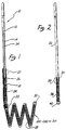
- Figure 1 is an enlarged partially cross-sectioned side view of a first embodiment of the distal end of the guidewire and tip of the invention.
- Figure 2 is an enlarged longitudinal cross section of a second embodiment of the guidewire and tip of the invention.
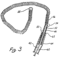
- Figure 3 is an enlarged side view of a third embodiment of the invention with a microcatheter portion cut away in a longitudinal cross-sectional view.
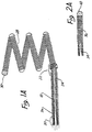
- Figure 4 is a simplified depiction of the wire of Figure 3 shown disposed within a simple cranial aneurysm.
- Figure 5 is a depiction of the wire of Figure 4 shown after electrolytic detachment of the tip.
- Figure 6 is a plan view of another embodiment of the guidewire and tip portion wherein the type is provided with a plurality of polyester filamentary hairs.
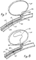
- Figures 7 and 8 are a diagrammatic depictions of the use of the invention wherein position markers have been provided on the catheter and wire to assist in proper fluoroscopic manipulation.
- Figure 9 is a simplified cross-sectional view of the catheter and wire showing a ground electrode disposed on the distal tip of the catheter.
- An artery, vein, aneurysm, vascular malformation or arterial fistula is occluded through endovascular occlusion by the endovascular insertion of a platinum tip into the vascular cavity.
- the vascular cavity is packed with the tip to obstruct blood flow or access of blood in the cavity such that the blood clots in the cavity and an occlusion if formed.
- the tip may be elongate and flexible so that it packs the cavity by being folded upon itself a multiple number of times, or may pack the cavity by virtue of a filamentary or fuzzy structure of the tip. The tip is then separated from the wire mechanically or by electrolytic separation of the tip from the wire.
- the wire and the microcatheter are thereafter removed leaving the tip embedded in the thrombus formed within the vascular cavity. Movement of wire in the microcatheter is more easily tracked by providing a radioopaque proximal marker on the microcatheter and a corresponding indicator marker on the wire. Electrothrombosis is facilitate by placing the ground electrode on the distal end of the microcatheter and flowing current between the microcatheter electrode and the tip.
- a portion of the wire connected between the tip and the body of the wire is comprised of stainless steel and exposed to the bloodstream so that upon continued application of a positive current to the exposed portion, the exposed portion is corroded away at least at one location and the tip is separated from the body of the wire.
- Figure 1 is an enlarged side view of a first embodiment of the distal end of the wire and tip shown in partial cross-sectional view.
- a conventional Teflon laminated or similarly insulated stainless steel wire 10 is disposed within a protective microcatheter (not shown).
- Stainless steel wire 10 is approximately 0.010 - 0.020 inch (0.254-0.508 mm) in diameter.
- wire 10 is tapered at its distal end to form a conical section 12 which joins a section 14 of reduced diameter which extends longitudinally along a length 16 of wire 10. Section 16 then narrows gradually down to a thin threadlike portion 18 beginning at a first bonding location 20 and ending at a second bonding location 22.
- the stainless steel wire 10 comprised of that portion disposed within the microcatheter body, tapered section 12, reduced diameter section 16 and threadlike section 18, is collectively referred to as a core wire which typically is 50 - 300 cm. in length.
- the portion of the core wire extending from tapered section 12 to second bonding location 22 is collectively referred to as the grinding length and may typically be between 20 and 50 cm. in length.
- Reduced diameter portion 14 and at least part of sections 12 and first bonding location 20 may be covered with an insulating Teflon laminate 24 which encapsulates the underlying portion of wire 10 to prevent contact with the blood.
- a stainless steel coil 26 is soldered to the proximate end of threadlike portion 18 of wire 10 at first bonding location 20.
- Stainless steel coil 26 is typically 3 to 10 cm. in length and like wire 10 has a diameter typically between 0.010 to 0.020 inch (0.254-0.508 mm).
- the distal end of stainless steel coil 26 is soldered to the distal end of threadlike portion 18 of wire 10 and to the proximal end of a platinum secondary coil 28 at second bonding location 22.
- Secondary coil 28 itself forms a spiral or helix typically between 2 to 10 mm. in diameter.
- the helical envelope formed by secondary coil 28 may be cylindrical or conical.
- secondary coil 28 is between approximately 0.010 and 0.020 inch (0.254-0508 mm) in diameter.
- the diameter of the wire itself forming stainless steel coil 26 and coil 28 is approximately between 0.001 - 0.005 inch.
- the distal end of secondary coil 28 is provided with a platinum soldered tip 30 to form a rounded and smooth termination to avoid puncturing the aneurysm or tearing tissue.
- secondary coil 28 Although prebiased to form a cylindrical or conical envelope, secondary coil 28 is extremely soft and its overall shape is easily deformed. When inserted within the microcatheter (not shown), secondary coil 28 is easily straightened to lie axially within the microcatheter. Once disposed out of the tip of the microcatheter, secondary coil 28 forms the shape shown in Figure 1 and may similarly be loosely deformed to the interior shape of the aneurysm.
- a direct current is applied to wire 10 from a voltage source exterior to the body.
- the positive charge on secondary coil 28 within the cavity of the aneurysm causes a thrombus to form within the aneurysm by electrothrombosis.
- Detachment of the tip occurs either: (1) by continued application of current for a predetermined time when the portion 18 is exposed to blood; or (2) by movement of the wire to expose portion 18 to blood followed by continued current application for a predetermined time.
- both threadlike portion and stainless steel coil 26 will be completely disintegrated at least at one point, thereby allowing wire 10 to be withdrawn from the vascular space while leaving secondary coil 28 embedded within the thrombus formed within the aneurysm.
- FIG. 2 illustrates in enlarged partially cross-sectional view a second embodiment of the invention.
- Stainless steel core 32 terminates in a conical distal portion 34.
- Stainless steel coil 36 shown in cross-sectional view, is soldered to distal portion 34 of wire 32 at bonding location 38.
- the opposing end of the stainless steel coil 36 is provided with a soldered, rounded platinum tip 40.
- stainless steel core wire 32 is approximately 0.010 inch in diameter with the length of stainless steel coil 36 being approximately 8 cm. with the longitudinal length of platinum tip 40 being between 3 and 10 mm.
- the total length of wire 32 from tip 40 to the proximate end is approximately 150 cm.
- the embodiment of Figure 2 is utilized in exactly the same manner as described above in connection with Figure 1 to form a thrombic mass within an aneurysm or other vascular cavity.
- the embodiment of Figure 2 is distinguished from that shown in Figure 1 by the absence of the extension of stainless core 32 through coil 36 to tip 40.
- no inner core or reinforcement is provided within stainless steel coil 36.
- Threadlike portion 18 is provided in the embodiment of Figure 1 to allow increased tensile strength of the wire.
- a degree of flexibility of the wire is sacrificed by the inclusion even of threadlike tip 18, so that the embodiment of Figure 2 provides a more flexible tip, at least for that portion of the micro-guidewire constituting the stainless steel coil 36.
- Thinned and threadlike portion guidewires disposed concentrically within coiled portions are well known and are shown in Antoshkiw , "Disposable Guidewire” , U.S. Patent 3,789,841 (1974); Sepetka et al ., "Guidewire Device” , U.S. Patent 4,832,047 (1989); Engelson , "Catheter Guidewire” , U.S. Patent 4,884,579 (1989); Samson et al ., "Guidewire for Catheters” , U.S. Patent 4,538,622 (1985); and Samson et al ., "Catheter Guidewire with Short Spring Tip and Method of Using the Same” , U.S. Patent 4,554,929 (1985).
- FIG. 3 shows an enlarged side view of a wire, generally denoted by reference numeral 42, disposed within a microcatheter 44 shown in cross-sectional view.
- a stainless steel coil 46 is soldered to a conical portion 48 of wire 22 at a first bonding location 50.
- a thin threadlike extension 52 is then longitudinally disposed within stainless steel coil 46 to a second bonding location 54 where stainless steel wire 46 and threadlike portion 52 are soldered to a soft platinum coil 56.
- Platinum coil 56 is not prebiased, nor does it contain any internal reinforcement, but is a free and open coil similar in that respect to stainless steel coil 36 of the embodiment of Figure 2.
- platinum coil 56 is particularly distinguished by its length of approximately 1 to 50 cm. and by its flexibility.
- the platinum or platinum alloy used is particularly pliable and the diameter of the wire used to form platinum coil 56 is approximately 0.001 - 0.005 inch in diameter.
- the distal end of platinum coil 56 is provided with a smooth and rounded platinum tip 58 similar in that respect to tips 30 and 40 of Figures 1 and 2, respectively.
- microcatheter 44 When coil 56 is disposed within microcatheter 44, it lies along the longitudinal lumen 60 defined by microcatheter 44.
- the distal end 62 of microcatheter 60 is then placed into the neck of the aneurysm and the wire 42 is advanced, thereby feeding tip 58 in platinum coil 56 into aneurysm 64 until bonding location 50 resides in the neck of the aneurysm as best depicted in the diagrammatic cross-sectional view of Figure 4.
- Figure 4 illustrates the insertion of the embodiment of Figure 3 within a vessel 66 with distal tip of microcatheter 44 positioned near neck 68 of aneurysm 64.
- Coil 56 is fed into aneurysm 64 until at least a portion of stainless steel coil 46 is exposed beyond the distal up 62 of microcatheter 44.
- a positive electric current of approximately 0.01 to 2 milliamps at 0.1 - 6 volts is applied to wire 42 to form the thrombus. Typically a thrombus will form within three to five minutes.
- the negative pole 72 of voltage source 70 is typically placed over and in contact with the skin.
- tip 58 and coil 56 are detached from wire 42 by electrolytic disintegration of at least one portion of stainless steel coil 46. In the illustrated embodiment this is accomplished by continued application of current until the total time of current application is almost approximately four minutes.
- At least one portion of stainless steel coil 46 will be completely dissolved through by electrolytic action within 3 to 10 minutes, usually about 4 minutes.
- wire 42, microcatheter 44 and the remaining portion of coil 46 still attached to wire 42 are removed from vessel 66, leaving aneurysm 64 completely occluded as diagrammatically depicted in Figure 5 by thrombus 74. It will be appreciated that the time of disintegration may be varied by altering the dimensions of the portions of the wire and/or the current.
- the process is practiced under fluoroscopic control with local anesthesia at the groin.
- a transfemoral microcatheter is utilized to treat the cerebral aneurysm.
- the platinum is not affected by electrolysis and the remaining portions of the microcatheter are insulated either by a Teflon lamination directly on wire 42 and/or by microcatheter 44. Only the exposed portion of the wire 46 is affected by the electrolysis.
- thrombus 74 continues to form even after detachment from wire 42. It is believed that a positive charge is retained on or near coil 56 which therefore continues to attract platelets, white blood cells, red blood cells and fibrinogen within aneurysm 64.
- Wire 10 has a tapering end portion 14 covered with a Teflon laminate 24 similar to that described in connection with the embodiment of Figure 1.
- Wire 10 is attached by means of a mechanical coupling 100 to a platinum coil 102 which has a plurality of filaments or fine hairs 104 extending therefrom.
- hairs 104 have a length as may be determined from the size of the vascular cavity in which coil 102 is to be used. For example, in a small vessel hair lengths of up to 1 mm are contemplated.
- An example of polyester filaments or hairs attached to a coil which was not used in electrothrombosis may be seen in the copending application entitled Vasoocclusion Coil with Attached Fiberous Elements, filed Oct. 2, 1991, serial number 07/771,013.
- Coil 102 has sufficient length and flexibility that it can be inserted or coiled loosely into the vacular cavity.
- the length of coil 102 need not be so long that the coil itself is capable of being multiply folded on itself and fill or substantially fill the vascular cavity.
- Hairs 104 extending from coil 102 serve to substantially pack, fill or at least impede blood flow or access in the vascular cavity.
- Hairs 104 which are generally inclined backwardly away from extreme tip 106 when delivered, are thus easily able to slide forward with little friction through restrictions in the vessels and aneurysm. Additionally, hairs 104 do not have sufficient length, strength or sharpness to provide any substantial risk or potential for a puncture of the thin vascular wall.
- the plurality of hairs 104 when coiled within the vascular cavity, provide an extremely large surface for attachment of blood constituents to encourage and enhance the formation of a mechanical occlusion within the vascular opening.
- coil 102 is mechanically coupled to thin tapered portion 104 of wire 10 by means of a small drop of polyester 100.
- Polyester may be substituted for the gold solder of the previously described embodiments in order to reduce concern or risk of toxic reactions in the body.
- Tip portion 104 may also be mechanically separated from wire 10 by means other than electrolysis.
- One method is make the connection between tip 104 and wire 10 by means of a spring loaded mechanical clasp (not shown). The clasps are retained on tip 104 as long as the clasps remain inside of the catheter, but spring open and release tip 104 when extended from the catheter. The catheter and clasps may then be removed from the insertion site.
- This type of mechanical connection is described in the copending application entitled, "Detachable Pusher-Vasoocclusive Coil Assembly with Interlocking Coupling", filed Dec. 12, 1991 with serial number 07/806,979 which is incorporated herein by reference and assigned to Target Therapeutics Inc.
- wire 10 and tip portion 104 screw into each other and can be unscrewed from each other by rotation of the catheter or wire with respect to tip 104.
- An extendable sheath (not shown) in the microcatheter is advanced to size tip 104 to prevent its rotation with wire 10 during the unscrewing process.
- tip 104 may be effected by electrolysis.
- the electrolysing current may be concentrated on the sacrificial stainless steel portion of tip 104 by disposition of an insulative coating on the remaining platinum portion.
- tip 104 may be provided with a polyethylene coating save at least a portion of the stainless steel length. This has the effect of decreasing the time required to electrolytically sufficiently disintegrate the steel portion to allow detachment of the platinum tip, which is an advantageous feature in those cases where a large aneurysm must be treated and a multiple number of coils must be deployed within the aneurysm.
- wire 10 and platinum coil 102 in the embodiment Figure 6 or wire 10 and platinum coil 28, 36 and 56 in the embodiments of Figures 1-5 are radiopaque, there is still some difficulty when manipulating the device under fluoroscopy to be able to determine the exact position or movement of the probe relative to the aneurysm. This is particularly true when a large number of coils are deployed and one coil then radiographically hides another.
- Figure 7 illustrates an improvement of, for example, the embodiment of Figures 4 and 5.
- Microcatheter 144 is positioned so that its distal end 162 within vessel 66 is positioned at the opening aneurysm 64.
- Microcatheter 144 is provided with radiopaque marker 108 at distal tip 162, a tip marker.
- Radiopaque markers 108 and 110 are, for example, in the form of radiopaque rings made of platinum, approximately 1-3 mm in longitudinal length along the axis of microcatheter 144. Rings 110 and 108 are typically separated by about 3 cm on microcatheter 144.
- wire 10 has a radiopaque marker 112 defined on it such that marker 112 on wire 10 is approximately with aligned with marker 110 on microcatheter 14 when coil 56 is fully deployed into aneurysm 64. Typically, full deployment will place the solder or connection point 54 of the order of 2-3 mm past opening 68 of aneurysm 64.
- Distal marker 108 on microcatheter 144 is used to facilitate the location of the microcatheter tip, which can often be obscured by the coils which have been previously deployed.
- the coils are a varying lengths depending on the application or size of the aneurysm or vascular cavity being treated. Coil lengths of 4-40 cm are common. Therefore, even though the thinness of coil 56 may make it difficult to see under standard fluoroscopy and even though the fineness of wire 10 may similarly be obscured or partly obscured, radiopaque markers 108, 110 and 112 are clearly visible. Manipulation of wire 10 to proximal marker 110 can then easily be observed under conventional fluoroscopy even when there are some loss of resolution or fluoroscopic visual obstruction of the coil.
- FIG. 9 illustrates an alternative embodiment wherein microcatheter 144 is supplied with an end electrode 114 coupled to an electrical conductor 116 disposed along the length of microcatheter 144. Wire 116 is ultimately led back to voltage source 70 so that ring electrode 114 is used as the cathode during electrothrombosis instead of an exterior skin electrode 72.
- the electrical currents and electrical current paths which are set up during the electrothrombosis formation are local to the site of application which allows even smaller currents and voltages to be used to initiate electrothrombosis than in the situation when an exterior skin electrode must be utilized.
- the electrothrombosic current distributions are also better controlled and localized to the site of the thrombus formation. The possibility of stray thrombus formations occurring at unwanted sites or uncontrolled and possibly unwanted electrical current patterns being established elsewhere in the brain or body is therefore largely avoided.
- the shape of the tip or distal platinum coil used in combination with the wire according to the invention may be provided with a variety of shapes and envelopes.
- the composition of the microguidewire tip may be made of elements other than platinum including stainless steel, beryllium, copper and various alloys of the same with or without platinum.
- the diameter of the wire, various of the wire described above and the stainless steel coil immediately proximal to the detachable tip may be provided with differing diameters or cross sections to vary the times and current magnitudes necessary in order to effectuate electrolytic detachment from the tip.
- the invention may include conventional electronics connected to the proximal end of the wire for determining the exact instant of detachment of the distal tip from the wire.
Landscapes
- Health & Medical Sciences (AREA)
- Life Sciences & Earth Sciences (AREA)
- Surgery (AREA)
- Engineering & Computer Science (AREA)
- Animal Behavior & Ethology (AREA)
- Veterinary Medicine (AREA)
- Public Health (AREA)
- Biomedical Technology (AREA)
- Heart & Thoracic Surgery (AREA)
- General Health & Medical Sciences (AREA)
- Nuclear Medicine, Radiotherapy & Molecular Imaging (AREA)
- Molecular Biology (AREA)
- Medical Informatics (AREA)
- Vascular Medicine (AREA)
- Reproductive Health (AREA)
- Physics & Mathematics (AREA)
- Cardiology (AREA)
- Plasma & Fusion (AREA)
- Otolaryngology (AREA)
- Biophysics (AREA)
- Pulmonology (AREA)
- Anesthesiology (AREA)
- Hematology (AREA)
- Neurosurgery (AREA)
- Surgical Instruments (AREA)
- Pharmaceuticals Containing Other Organic And Inorganic Compounds (AREA)
- Acyclic And Carbocyclic Compounds In Medicinal Compositions (AREA)
- Prostheses (AREA)
- Media Introduction/Drainage Providing Device (AREA)
- Organic Low-Molecular-Weight Compounds And Preparation Thereof (AREA)
- Dental Preparations (AREA)
- Nonmetallic Welding Materials (AREA)
- Electrotherapy Devices (AREA)
Priority Applications (2)
| Application Number | Priority Date | Filing Date | Title |
|---|---|---|---|
| EP03007337A EP1323385A3 (fr) | 1992-02-24 | 1992-09-30 | Fil endovasculaire détachable de manière électrolytique pour formation de thrombus |
| EP00104781A EP1005837B2 (fr) | 1992-02-24 | 1992-09-30 | Appareil pour boucher une cavité vasculaire |
Applications Claiming Priority (3)
| Application Number | Priority Date | Filing Date | Title |
|---|---|---|---|
| US07/840,211 US5354295A (en) | 1990-03-13 | 1992-02-24 | In an endovascular electrolytically detachable wire and tip for the formation of thrombus in arteries, veins, aneurysms, vascular malformations and arteriovenous fistulas |
| US840211 | 1992-02-24 | ||
| EP92922392A EP0629125B1 (fr) | 1992-02-24 | 1992-09-30 | Système à microcathéter |
Related Parent Applications (2)
| Application Number | Title | Priority Date | Filing Date |
|---|---|---|---|
| EP92922392A Division EP0629125B1 (fr) | 1992-02-24 | 1992-09-30 | Système à microcathéter |
| EP92922392.3 Division | 1993-09-10 |
Related Child Applications (1)
| Application Number | Title | Priority Date | Filing Date |
|---|---|---|---|
| EP00104781A Division EP1005837B2 (fr) | 1992-02-24 | 1992-09-30 | Appareil pour boucher une cavité vasculaire |
Publications (3)
| Publication Number | Publication Date |
|---|---|
| EP0803230A2 true EP0803230A2 (fr) | 1997-10-29 |
| EP0803230A3 EP0803230A3 (fr) | 1997-11-12 |
| EP0803230B1 EP0803230B1 (fr) | 2000-11-02 |
Family
ID=25281739
Family Applications (6)
| Application Number | Title | Priority Date | Filing Date |
|---|---|---|---|
| EP03007337A Withdrawn EP1323385A3 (fr) | 1992-02-24 | 1992-09-30 | Fil endovasculaire détachable de manière électrolytique pour formation de thrombus |
| EP03010295A Expired - Lifetime EP1366720B1 (fr) | 1992-02-24 | 1992-09-30 | Fil endovasculaire détachable de manière électrolytique pour formation de thrombus |
| EP97112837A Expired - Lifetime EP0803230B1 (fr) | 1992-02-24 | 1992-09-30 | Fil endovasculaire détachable de manière électrolytique pour former de thrombus |
| EP92922392A Expired - Lifetime EP0629125B1 (fr) | 1992-02-24 | 1992-09-30 | Système à microcathéter |
| EP00104781A Expired - Lifetime EP1005837B2 (fr) | 1992-02-24 | 1992-09-30 | Appareil pour boucher une cavité vasculaire |
| EP97112838A Expired - Lifetime EP0804906B1 (fr) | 1992-02-24 | 1992-09-30 | Fil endovasculaire détachable de manière électrolytique pour former de thrombus |
Family Applications Before (2)
| Application Number | Title | Priority Date | Filing Date |
|---|---|---|---|
| EP03007337A Withdrawn EP1323385A3 (fr) | 1992-02-24 | 1992-09-30 | Fil endovasculaire détachable de manière électrolytique pour formation de thrombus |
| EP03010295A Expired - Lifetime EP1366720B1 (fr) | 1992-02-24 | 1992-09-30 | Fil endovasculaire détachable de manière électrolytique pour formation de thrombus |
Family Applications After (3)
| Application Number | Title | Priority Date | Filing Date |
|---|---|---|---|
| EP92922392A Expired - Lifetime EP0629125B1 (fr) | 1992-02-24 | 1992-09-30 | Système à microcathéter |
| EP00104781A Expired - Lifetime EP1005837B2 (fr) | 1992-02-24 | 1992-09-30 | Appareil pour boucher une cavité vasculaire |
| EP97112838A Expired - Lifetime EP0804906B1 (fr) | 1992-02-24 | 1992-09-30 | Fil endovasculaire détachable de manière électrolytique pour former de thrombus |
Country Status (14)
| Country | Link |
|---|---|
| US (2) | US5354295A (fr) |
| EP (6) | EP1323385A3 (fr) |
| JP (2) | JP3152399B2 (fr) |
| AT (5) | ATE314014T1 (fr) |
| AU (1) | AU673502B2 (fr) |
| CA (1) | CA2120779C (fr) |
| DE (5) | DE69233026T3 (fr) |
| DK (2) | DK1005837T4 (fr) |
| ES (3) | ES2192501T5 (fr) |
| FI (1) | FI941937A7 (fr) |
| GR (1) | GR3035159T3 (fr) |
| NO (2) | NO320812B1 (fr) |
| PT (2) | PT101162B (fr) |
| WO (1) | WO1993016650A1 (fr) |
Cited By (16)
| Publication number | Priority date | Publication date | Assignee | Title |
|---|---|---|---|---|
| WO2009073398A1 (fr) * | 2007-12-03 | 2009-06-11 | Boston Scientific Scimed, Inc. | Dispositif implantable avec une jonction détachable de façon électrolytique ayant de multiples câbles minces |
| USRE41029E1 (en) | 1990-03-13 | 2009-12-01 | The Regents Of The University Of California | Endovascular electrolytically detachable wire and tip for the formation of thrombus in arteries, veins, aneurysms, vascular malformations and arteriovenous fistulas |
| USRE42625E1 (en) | 1990-03-13 | 2011-08-16 | The Regents Of The University Of California | Endovascular electrolytically detachable wire and tip for the formation of thrombus in arteries, veins, aneurysms, vascular malformations and arteriovenous fistulas |
| USRE42662E1 (en) | 1990-03-13 | 2011-08-30 | The Regents Of The University Of California | Endovascular electrolytically detachable wire and tip for the formation of thrombus in arteries, veins, aneurysms, vascular malformations and arteriovenous fistulas |
| US8940003B2 (en) | 2008-02-22 | 2015-01-27 | Covidien Lp | Methods and apparatus for flow restoration |
| US9039749B2 (en) | 2010-10-01 | 2015-05-26 | Covidien Lp | Methods and apparatuses for flow restoration and implanting members in the human body |
| US9254134B2 (en) | 2004-01-21 | 2016-02-09 | Dendron Gmbh | Device for implanting electrically isolated occlusion helixes |
| US9326774B2 (en) | 2012-08-03 | 2016-05-03 | Covidien Lp | Device for implantation of medical devices |
| US9717503B2 (en) | 2015-05-11 | 2017-08-01 | Covidien Lp | Electrolytic detachment for implant delivery systems |
| US9808256B2 (en) | 2014-08-08 | 2017-11-07 | Covidien Lp | Electrolytic detachment elements for implant delivery systems |
| US9814466B2 (en) | 2014-08-08 | 2017-11-14 | Covidien Lp | Electrolytic and mechanical detachment for implant delivery systems |
| US9867622B2 (en) | 2014-04-11 | 2018-01-16 | Microvention, Inc. | Implant delivery system |
| US10076399B2 (en) | 2013-09-13 | 2018-09-18 | Covidien Lp | Endovascular device engagement |
| US10342683B2 (en) | 2002-07-19 | 2019-07-09 | Ussc Medical Gmbh | Medical implant having a curlable matrix structure and method of use |
| US10413310B2 (en) | 2007-10-17 | 2019-09-17 | Covidien Lp | Restoring blood flow and clot removal during acute ischemic stroke |
| US10722255B2 (en) | 2008-12-23 | 2020-07-28 | Covidien Lp | Systems and methods for removing obstructive matter from body lumens and treating vascular defects |
Families Citing this family (440)
| Publication number | Priority date | Publication date | Assignee | Title |
|---|---|---|---|---|
| US5569245A (en) | 1990-03-13 | 1996-10-29 | The Regents Of The University Of California | Detachable endovascular occlusion device activated by alternating electric current |
| US6425893B1 (en) * | 1990-03-13 | 2002-07-30 | The Regents Of The University Of California | Method and apparatus for fast electrolytic detachment of an implant |
| US5354295A (en) † | 1990-03-13 | 1994-10-11 | Target Therapeutics, Inc. | In an endovascular electrolytically detachable wire and tip for the formation of thrombus in arteries, veins, aneurysms, vascular malformations and arteriovenous fistulas |
| US5976131A (en) * | 1990-03-13 | 1999-11-02 | The Regents Of The University At California | Detachable endovascular occlusion device activated by alternating electric current |
| US5122136A (en) * | 1990-03-13 | 1992-06-16 | The Regents Of The University Of California | Endovascular electrolytically detachable guidewire tip for the electroformation of thrombus in arteries, veins, aneurysms, vascular malformations and arteriovenous fistulas |
| US5851206A (en) * | 1990-03-13 | 1998-12-22 | The Regents Of The University Of California | Method and apparatus for endovascular thermal thrombosis and thermal cancer treatment |
| DE4104702C2 (de) * | 1991-02-15 | 1996-01-18 | Malte Neuss | Implantate für Organwege in Wendelform |
| US5382259A (en) * | 1992-10-26 | 1995-01-17 | Target Therapeutics, Inc. | Vasoocclusion coil with attached tubular woven or braided fibrous covering |
| US5690666A (en) * | 1992-11-18 | 1997-11-25 | Target Therapeutics, Inc. | Ultrasoft embolism coils and process for using them |
| JP3486437B2 (ja) | 1992-12-09 | 2004-01-13 | テルモ株式会社 | 塞栓術用カテーテル |
| US5645082A (en) * | 1993-01-29 | 1997-07-08 | Cardima, Inc. | Intravascular method and system for treating arrhythmia |
| US5800453A (en) * | 1993-04-19 | 1998-09-01 | Target Therapeutics, Inc. | Detachable embolic coil assembly using interlocking hooks and slots |
| US5573547A (en) * | 1993-10-19 | 1996-11-12 | Leveen; Harry H. | Brush fixation method for attachment of tissues and occlusion of blood vessels |
| US5423829A (en) * | 1993-11-03 | 1995-06-13 | Target Therapeutics, Inc. | Electrolytically severable joint for endovascular embolic devices |
| US5624449A (en) * | 1993-11-03 | 1997-04-29 | Target Therapeutics | Electrolytically severable joint for endovascular embolic devices |
| FR2712797B1 (fr) * | 1993-11-26 | 1996-03-01 | Balt Extrusion | Système d'occlusion vasculaire. |
| WO1995019148A1 (fr) * | 1994-01-18 | 1995-07-20 | Endovascular, Inc. | Appareil et procede de ligature veineuse |
| JP2735393B2 (ja) * | 1994-03-03 | 1998-04-02 | ターゲット セラピュウティクス,インコーポレイテッド | 血管内塞栓装置の切り離し検出方法および装置 |
| US6117157A (en) * | 1994-03-18 | 2000-09-12 | Cook Incorporated | Helical embolization coil |
| DE29500381U1 (de) * | 1994-08-24 | 1995-07-20 | Schneidt, Bernhard, Ing.(grad.), 63571 Gelnhausen | Vorrichtung zum Verschließen eines Ductus, insbesondere des Ductus arteriosus |
| US5814062A (en) | 1994-12-22 | 1998-09-29 | Target Therapeutics, Inc. | Implant delivery assembly with expandable coupling/decoupling mechanism |
| US5578074A (en) * | 1994-12-22 | 1996-11-26 | Target Therapeutics, Inc. | Implant delivery method and assembly |
| IL116561A0 (en) * | 1994-12-30 | 1996-03-31 | Target Therapeutics Inc | Severable joint for detachable devices placed within the body |
| US5702421A (en) * | 1995-01-11 | 1997-12-30 | Schneidt; Bernhard | Closure device for closing a vascular opening, such as patent ductus arteriosus |
| JP3625837B2 (ja) * | 1995-01-27 | 2005-03-02 | シメッド ライフ システムズ,インコーポレイテッド | 塞栓装置 |
| US6171326B1 (en) | 1998-08-27 | 2001-01-09 | Micrus Corporation | Three dimensional, low friction vasoocclusive coil, and method of manufacture |
| US6638291B1 (en) | 1995-04-20 | 2003-10-28 | Micrus Corporation | Three dimensional, low friction vasoocclusive coil, and method of manufacture |
| US5645558A (en) * | 1995-04-20 | 1997-07-08 | Medical University Of South Carolina | Anatomically shaped vasoocclusive device and method of making the same |
| US5911731A (en) * | 1995-04-20 | 1999-06-15 | Target Therapeutics, Inc. | Anatomically shaped vasoocclusive devices |
| US8790363B2 (en) | 1995-04-20 | 2014-07-29 | DePuy Synthes Products, LLC | Three dimensional, low friction vasoocclusive coil, and method of manufacture |
| US5639277A (en) * | 1995-04-28 | 1997-06-17 | Target Therapeutics, Inc. | Embolic coils with offset helical and twisted helical shapes |
| US5702373A (en) * | 1995-08-31 | 1997-12-30 | Target Therapeutics, Inc. | Composite super-elastic alloy braid reinforced catheter |
| DK0782463T3 (da) * | 1995-04-28 | 2000-06-05 | Target Therapeutics Inc | Højtydende flettet kateter |
| US6143007A (en) * | 1995-04-28 | 2000-11-07 | Target Therapeutics, Inc. | Method for making an occlusive device |
| US6824553B1 (en) | 1995-04-28 | 2004-11-30 | Target Therapeutics, Inc. | High performance braided catheter |
| US6059779A (en) * | 1995-04-28 | 2000-05-09 | Target Therapeutics, Inc. | Delivery catheter for electrolytically detachable implant |
| JP3007022B2 (ja) * | 1995-05-19 | 2000-02-07 | 株式会社カネカメディックス | 加熱用高周波電源装置 |
| US5624461A (en) * | 1995-06-06 | 1997-04-29 | Target Therapeutics, Inc. | Three dimensional in-filling vaso-occlusive coils |
| US5766160A (en) * | 1995-06-06 | 1998-06-16 | Target Therapeutics, Inc. | Variable stiffness coils |
| NO962336L (no) * | 1995-06-06 | 1996-12-09 | Target Therapeutics Inc | Vaso-okklusiv spiral |
| US6176240B1 (en) | 1995-06-07 | 2001-01-23 | Conceptus, Inc. | Contraceptive transcervical fallopian tube occlusion devices and their delivery |
| US6132438A (en) * | 1995-06-07 | 2000-10-17 | Ep Technologies, Inc. | Devices for installing stasis reducing means in body tissue |
| US20110077672A1 (en) * | 1995-06-07 | 2011-03-31 | Fleischman Sidney D | Devices For Installing Stasis Reducing Means In Body Tissue |
| US6705323B1 (en) | 1995-06-07 | 2004-03-16 | Conceptus, Inc. | Contraceptive transcervical fallopian tube occlusion devices and methods |
| US6293942B1 (en) | 1995-06-23 | 2001-09-25 | Gyrus Medical Limited | Electrosurgical generator method |
| US6015406A (en) * | 1996-01-09 | 2000-01-18 | Gyrus Medical Limited | Electrosurgical instrument |
| CA2224858C (fr) | 1995-06-23 | 2006-11-14 | Gyrus Medical Limited | Instrument electrochirurgical |
| US6780180B1 (en) | 1995-06-23 | 2004-08-24 | Gyrus Medical Limited | Electrosurgical instrument |
| AU703433B2 (en) | 1995-06-23 | 1999-03-25 | Gyrus Medical Limited | An electrosurgical instrument |
| WO1997001368A1 (fr) * | 1995-06-26 | 1997-01-16 | Trimedyne, Inc. | Dispositif de liberation d'element therapeutique |
| US5582619A (en) * | 1995-06-30 | 1996-12-10 | Target Therapeutics, Inc. | Stretch resistant vaso-occlusive coils |
| NO962761L (no) * | 1995-06-30 | 1997-01-02 | Target Therapeutics Inc | Strekkmotstandige vasookklusive spiraler |
| US5853418A (en) * | 1995-06-30 | 1998-12-29 | Target Therapeutics, Inc. | Stretch resistant vaso-occlusive coils (II) |
| US6013084A (en) | 1995-06-30 | 2000-01-11 | Target Therapeutics, Inc. | Stretch resistant vaso-occlusive coils (II) |
| US5743905A (en) * | 1995-07-07 | 1998-04-28 | Target Therapeutics, Inc. | Partially insulated occlusion device |
| US6019757A (en) * | 1995-07-07 | 2000-02-01 | Target Therapeutics, Inc. | Endoluminal electro-occlusion detection apparatus and method |
| US5601600A (en) * | 1995-09-08 | 1997-02-11 | Conceptus, Inc. | Endoluminal coil delivery system having a mechanical release mechanism |
| US6287315B1 (en) * | 1995-10-30 | 2001-09-11 | World Medical Manufacturing Corporation | Apparatus for delivering an endoluminal prosthesis |
| DE19547617C1 (de) * | 1995-12-20 | 1997-09-18 | Malte Neus | Vorrichtung zum Einführen und Replazieren von Implantaten, sowie Set aus dieser Vorrichtung und einem Implantat |
| US6013076A (en) | 1996-01-09 | 2000-01-11 | Gyrus Medical Limited | Electrosurgical instrument |
| US6090106A (en) | 1996-01-09 | 2000-07-18 | Gyrus Medical Limited | Electrosurgical instrument |
| JP2000504594A (ja) * | 1996-02-02 | 2000-04-18 | トランスバスキュラー インコーポレイテッド | 血管内の流れを遮断する方法及び装置 |
| US6270495B1 (en) | 1996-02-22 | 2001-08-07 | Radiotherapeutics Corporation | Method and device for enhancing vessel occlusion |
| US5649949A (en) * | 1996-03-14 | 1997-07-22 | Target Therapeutics, Inc. | Variable cross-section conical vasoocclusive coils |
| US7604633B2 (en) | 1996-04-12 | 2009-10-20 | Cytyc Corporation | Moisture transport system for contact electrocoagulation |
| US6813520B2 (en) | 1996-04-12 | 2004-11-02 | Novacept | Method for ablating and/or coagulating tissue using moisture transport |
| US6066139A (en) * | 1996-05-14 | 2000-05-23 | Sherwood Services Ag | Apparatus and method for sterilization and embolization |
| US5868754A (en) * | 1996-06-12 | 1999-02-09 | Target Therapeutics, Inc. | Medical retrieval device |
| US6565561B1 (en) | 1996-06-20 | 2003-05-20 | Cyrus Medical Limited | Electrosurgical instrument |
| GB9612993D0 (en) | 1996-06-20 | 1996-08-21 | Gyrus Medical Ltd | Electrosurgical instrument |
| GB2314274A (en) | 1996-06-20 | 1997-12-24 | Gyrus Medical Ltd | Electrode construction for an electrosurgical instrument |
| US6190402B1 (en) * | 1996-06-21 | 2001-02-20 | Musc Foundation For Research Development | Insitu formable and self-forming intravascular flow modifier (IFM) and IFM assembly for deployment of same |
| US6066158A (en) * | 1996-07-25 | 2000-05-23 | Target Therapeutics, Inc. | Mechanical clot encasing and removal wire |
| US5972019A (en) * | 1996-07-25 | 1999-10-26 | Target Therapeutics, Inc. | Mechanical clot treatment device |
| US5980514A (en) | 1996-07-26 | 1999-11-09 | Target Therapeutics, Inc. | Aneurysm closure device assembly |
| US6096034A (en) * | 1996-07-26 | 2000-08-01 | Target Therapeutics, Inc. | Aneurysm closure device assembly |
| US5980519A (en) * | 1996-07-30 | 1999-11-09 | Symbiosis Corporation | Electrocautery probe with variable morphology electrode |
| US5823198A (en) | 1996-07-31 | 1998-10-20 | Micro Therapeutics, Inc. | Method and apparatus for intravasculer embolization |
| JP3784112B2 (ja) * | 1996-08-15 | 2006-06-07 | 株式会社カネカメディックス | コイル状塞栓物質 |
| US5964797A (en) | 1996-08-30 | 1999-10-12 | Target Therapeutics, Inc. | Electrolytically deployable braided vaso-occlusion device |
| US5690667A (en) | 1996-09-26 | 1997-11-25 | Target Therapeutics | Vasoocclusion coil having a polymer tip |
| US5895391A (en) * | 1996-09-27 | 1999-04-20 | Target Therapeutics, Inc. | Ball lock joint and introducer for vaso-occlusive member |
| US20010041900A1 (en) * | 1999-12-21 | 2001-11-15 | Ovion, Inc. | Occluding device and method of use |
| US7073504B2 (en) | 1996-12-18 | 2006-07-11 | Ams Research Corporation | Contraceptive system and method of use |
| GB9626512D0 (en) | 1996-12-20 | 1997-02-05 | Gyrus Medical Ltd | An improved electrosurgical generator and system |
| US5733329A (en) * | 1996-12-30 | 1998-03-31 | Target Therapeutics, Inc. | Vaso-occlusive coil with conical end |
| US5830230A (en) * | 1997-03-07 | 1998-11-03 | Micro Therapeutics, Inc. | Method of intracranial vascular embolotherapy using self anchoring coils |
| US5906618A (en) * | 1997-03-20 | 1999-05-25 | Vanderbilt University | Microcatheter with auxiliary parachute guide structure |
| US6063070A (en) * | 1997-08-05 | 2000-05-16 | Target Therapeutics, Inc. | Detachable aneurysm neck bridge (II) |
| AU8772198A (en) | 1997-08-05 | 1999-03-08 | Target Therapeutics, Inc. | Detachable aneurysm neck bridge |
| US6711436B1 (en) | 1997-08-08 | 2004-03-23 | Duke University | Compositions, apparatus and methods for facilitating surgical procedures |
| US6086577A (en) * | 1997-08-13 | 2000-07-11 | Scimed Life Systems, Inc. | Detachable aneurysm neck bridge (III) |
| US6322576B1 (en) | 1997-08-29 | 2001-11-27 | Target Therapeutics, Inc. | Stable coil designs |
| US6156061A (en) | 1997-08-29 | 2000-12-05 | Target Therapeutics, Inc. | Fast-detaching electrically insulated implant |
| US5984929A (en) * | 1997-08-29 | 1999-11-16 | Target Therapeutics, Inc. | Fast detaching electronically isolated implant |
| US6860893B2 (en) | 1997-08-29 | 2005-03-01 | Boston Scientific Scimed, Inc. | Stable coil designs |
| US6066149A (en) | 1997-09-30 | 2000-05-23 | Target Therapeutics, Inc. | Mechanical clot treatment device with distal filter |
| US6074407A (en) | 1997-10-14 | 2000-06-13 | Target Therapeutics, Inc. | Delivery catheter for occlusive implants |
| US6304769B1 (en) | 1997-10-16 | 2001-10-16 | The Regents Of The University Of California | Magnetically directable remote guidance systems, and methods of use thereof |
| US6511468B1 (en) * | 1997-10-17 | 2003-01-28 | Micro Therapeutics, Inc. | Device and method for controlling injection of liquid embolic composition |
| JP4130234B2 (ja) * | 1997-10-30 | 2008-08-06 | 株式会社カネカメディックス | 生体内留置部材配置用医療用具 |
| US6241691B1 (en) | 1997-12-05 | 2001-06-05 | Micrus Corporation | Coated superelastic stent |
| US6168570B1 (en) | 1997-12-05 | 2001-01-02 | Micrus Corporation | Micro-strand cable with enhanced radiopacity |
| US6136015A (en) | 1998-08-25 | 2000-10-24 | Micrus Corporation | Vasoocclusive coil |
| US6159165A (en) | 1997-12-05 | 2000-12-12 | Micrus Corporation | Three dimensional spherical micro-coils manufactured from radiopaque nickel-titanium microstrand |
| US6036720A (en) * | 1997-12-15 | 2000-03-14 | Target Therapeutics, Inc. | Sheet metal aneurysm neck bridge |
| US6203547B1 (en) | 1997-12-19 | 2001-03-20 | Target Therapeutics, Inc. | Vaso-occlusion apparatus having a manipulable mechanical detachment joint and a method for using the apparatus |
| US6475227B2 (en) | 1997-12-24 | 2002-11-05 | Scimed Life Systems, Inc. | Vaso-occlusion apparatus having a mechanically expandable detachment joint and a method for using the apparatus |
| US5873907A (en) * | 1998-01-27 | 1999-02-23 | Endotex Interventional Systems, Inc. | Electrolytic stent delivery system and methods of use |
| US6022369A (en) * | 1998-02-13 | 2000-02-08 | Precision Vascular Systems, Inc. | Wire device with detachable end |
| US6346091B1 (en) * | 1998-02-13 | 2002-02-12 | Stephen C. Jacobsen | Detachable coil for aneurysm therapy |
| US5941888A (en) * | 1998-02-18 | 1999-08-24 | Target Therapeutics, Inc. | Vaso-occlusive member assembly with multiple detaching points |
| US6077260A (en) | 1998-02-19 | 2000-06-20 | Target Therapeutics, Inc. | Assembly containing an electrolytically severable joint for endovascular embolic devices |
| GB9807303D0 (en) | 1998-04-03 | 1998-06-03 | Gyrus Medical Ltd | An electrode assembly for an electrosurgical instrument |
| US6168615B1 (en) | 1998-05-04 | 2001-01-02 | Micrus Corporation | Method and apparatus for occlusion and reinforcement of aneurysms |
| US8551082B2 (en) | 1998-05-08 | 2013-10-08 | Cytyc Surgical Products | Radio-frequency generator for powering an ablation device |
| US6293960B1 (en) * | 1998-05-22 | 2001-09-25 | Micrus Corporation | Catheter with shape memory polymer distal tip for deployment of therapeutic devices |
| CA2334223C (fr) | 1998-06-04 | 2008-11-18 | New York University | Dispositifs endovasculaires a couche mince et procedes permettant de traiter et de prevenir un accident cerebrovasculaire |
| US6139564A (en) * | 1998-06-16 | 2000-10-31 | Target Therapeutics Inc. | Minimally occlusive flow disruptor stent for bridging aneurysm necks |
| US5980550A (en) | 1998-06-18 | 1999-11-09 | Target Therapeutics, Inc. | Water-soluble coating for bioactive vasoocclusive devices |
| US5935148A (en) * | 1998-06-24 | 1999-08-10 | Target Therapeutics, Inc. | Detachable, varying flexibility, aneurysm neck bridge |
| US6656218B1 (en) | 1998-07-24 | 2003-12-02 | Micrus Corporation | Intravascular flow modifier and reinforcement device |
| US6165194A (en) | 1998-07-24 | 2000-12-26 | Micrus Corporation | Intravascular flow modifier and reinforcement device |
| US6149664A (en) * | 1998-08-27 | 2000-11-21 | Micrus Corporation | Shape memory pusher introducer for vasoocclusive devices |
| US6296622B1 (en) | 1998-12-21 | 2001-10-02 | Micrus Corporation | Endoluminal device delivery system using axially recovering shape memory material |
| US6500149B2 (en) | 1998-08-31 | 2002-12-31 | Deepak Gandhi | Apparatus for deployment of micro-coil using a catheter |
| US6478773B1 (en) | 1998-12-21 | 2002-11-12 | Micrus Corporation | Apparatus for deployment of micro-coil using a catheter |
| US6224610B1 (en) | 1998-08-31 | 2001-05-01 | Micrus Corporation | Shape memory polymer intravascular delivery system with heat transfer medium |
| EP1109499B1 (fr) | 1998-09-04 | 2007-08-15 | Boston Scientific Limited | Piece de fermeture detachable pour collet anevrysmal |
| US7410482B2 (en) * | 1998-09-04 | 2008-08-12 | Boston Scientific-Scimed, Inc. | Detachable aneurysm neck bridge |
| US6277126B1 (en) * | 1998-10-05 | 2001-08-21 | Cordis Neurovascular Inc. | Heated vascular occlusion coil development system |
| US6277125B1 (en) | 1998-10-05 | 2001-08-21 | Cordis Neurovascular, Inc. | Embolic coil deployment system with retaining jaws |
| AU6288799A (en) | 1998-10-09 | 2000-05-01 | Cook Incorporated | Vasoocclusion coil device having a core therein |
| US6569179B2 (en) | 1998-11-10 | 2003-05-27 | Scimed Life Systems, Inc. | Bioactive three loop coil |
| US6723112B2 (en) | 1998-11-10 | 2004-04-20 | Scimed Life Systems, Inc. | Bioactive three loop coil |
| US8016852B2 (en) * | 1998-11-10 | 2011-09-13 | Stryker Corporation | Bioactive components for incorporation with vaso-occlusive members |
| US6187024B1 (en) | 1998-11-10 | 2001-02-13 | Target Therapeutics, Inc. | Bioactive coating for vaso-occlusive devices |
| US6102932A (en) * | 1998-12-15 | 2000-08-15 | Micrus Corporation | Intravascular device push wire delivery system |
| US6383204B1 (en) | 1998-12-15 | 2002-05-07 | Micrus Corporation | Variable stiffness coil for vasoocclusive devices |
| DE69814411T2 (de) | 1998-12-16 | 2004-04-01 | Arthesys | Kathetersystem zum hydraulischen Auslösen von Embolisierungsspiralen |
| US6835185B2 (en) | 1998-12-21 | 2004-12-28 | Micrus Corporation | Intravascular device deployment mechanism incorporating mechanical detachment |
| US6165140A (en) | 1998-12-28 | 2000-12-26 | Micrus Corporation | Composite guidewire |
| US7449019B2 (en) | 1999-01-25 | 2008-11-11 | Smith & Nephew, Inc. | Intervertebral decompression |
| US6221066B1 (en) | 1999-03-09 | 2001-04-24 | Micrus Corporation | Shape memory segmented detachable coil |
| US6352531B1 (en) | 1999-03-24 | 2002-03-05 | Micrus Corporation | Variable stiffness optical fiber shaft |
| US6887235B2 (en) | 1999-03-24 | 2005-05-03 | Micrus Corporation | Variable stiffness heating catheter |
| US6267776B1 (en) * | 1999-05-03 | 2001-07-31 | O'connell Paul T. | Vena cava filter and method for treating pulmonary embolism |
| US6648854B1 (en) | 1999-05-14 | 2003-11-18 | Scimed Life Systems, Inc. | Single lumen balloon-tipped micro catheter with reinforced shaft |
| US6458137B1 (en) | 1999-05-26 | 2002-10-01 | Cook Incorporated | Assembly for positioning an embolization coil in the vascular system and a method of introducing a detachable embolization coil |
| EP1867300A3 (fr) * | 1999-06-02 | 2008-02-27 | Sethel Interventional, Inc. | Dispositif intracorporel occlusif |
| US6280457B1 (en) * | 1999-06-04 | 2001-08-28 | Scimed Life Systems, Inc. | Polymer covered vaso-occlusive devices and methods of producing such devices |
| US6663607B2 (en) | 1999-07-12 | 2003-12-16 | Scimed Life Systems, Inc. | Bioactive aneurysm closure device assembly and kit |
| AU6058000A (en) * | 1999-07-12 | 2001-01-30 | Scimed Life Systems, Inc. | Liquid based vaso-occlusive compositions |
| US6312421B1 (en) | 1999-07-23 | 2001-11-06 | Neurovasx, Inc. | Aneurysm embolization material and device |
| US6309367B1 (en) | 1999-07-23 | 2001-10-30 | Neurovasx, Inc. | Aneurysm shield |
| US6689120B1 (en) | 1999-08-06 | 2004-02-10 | Boston Scientific Scimed, Inc. | Reduced profile delivery system |
| ES2354955T3 (es) | 1999-08-23 | 2011-03-21 | Conceptus, Inc. | Sistema de catéter de inserción / despliegue para la anticoncepcón intrafalopiana . |
| US6709667B1 (en) | 1999-08-23 | 2004-03-23 | Conceptus, Inc. | Deployment actuation system for intrafallopian contraception |
| US8048104B2 (en) * | 2000-10-30 | 2011-11-01 | Dendron Gmbh | Device for the implantation of occlusion spirals |
| US6342063B1 (en) | 2000-01-26 | 2002-01-29 | Scimed Life Systems, Inc. | Device and method for selectively removing a thrombus filter |
| JP4898993B2 (ja) * | 2000-01-28 | 2012-03-21 | クック メディカル テクノロジーズ エルエルシー | 複数本のワイヤを備えている脈管内医療装置 |
| US6397850B1 (en) | 2000-02-09 | 2002-06-04 | Scimed Life Systems Inc | Dual-mode apparatus and method for detection of embolic device detachment |
| US7740637B2 (en) | 2000-02-09 | 2010-06-22 | Micrus Endovascular Corporation | Apparatus and method for deployment of a therapeutic device using a catheter |
| ES2391763T3 (es) | 2000-04-07 | 2012-11-29 | Collagen Matrix, Inc. | Dispositivo de embolización |
| JP2004505715A (ja) | 2000-08-11 | 2004-02-26 | サイムド ライフ システムズ, インコーポレイテッド | 可変の柔軟性の脈管閉塞コイル |
| US6544275B1 (en) | 2000-08-11 | 2003-04-08 | Scimed Life Systems, Inc. | Vaso-occlusive coils with selectively flattened areas |
| US6855154B2 (en) | 2000-08-11 | 2005-02-15 | University Of Louisville Research Foundation, Inc. | Endovascular aneurysm treatment device and method |
| US6579308B1 (en) * | 2000-11-28 | 2003-06-17 | Scimed Life Systems, Inc. | Stent devices with detachable distal or proximal wires |
| US6676657B2 (en) | 2000-12-07 | 2004-01-13 | The United States Of America As Represented By The Department Of Health And Human Services | Endoluminal radiofrequency cauterization system |
| US6527790B2 (en) | 2000-12-07 | 2003-03-04 | Scimed Life Systems, Inc. | Intravascular balloon catheter for embolic coil delivery |
| US6540657B2 (en) * | 2000-12-28 | 2003-04-01 | Scimed Life Systems, Inc. | Apparatus and method for internally inducing a magnetic field in an aneurysm to embolize aneurysm with magnetically-controllable substance |
| US6540733B2 (en) * | 2000-12-29 | 2003-04-01 | Corazon Technologies, Inc. | Proton generating catheters and methods for their use in enhancing fluid flow through a vascular site occupied by a calcified vascular occlusion |
| US8721625B2 (en) * | 2001-01-26 | 2014-05-13 | Cook Medical Technologies Llc | Endovascular medical device with plurality of wires |
| US7294137B2 (en) * | 2001-03-27 | 2007-11-13 | Boston Scientific Scimed | Device for multi-modal treatment of vascular lesions |
| US6602269B2 (en) | 2001-03-30 | 2003-08-05 | Scimed Life Systems | Embolic devices capable of in-situ reinforcement |
| US20020193812A1 (en) * | 2001-05-04 | 2002-12-19 | Concentric Medical | Hydrogel vaso-occlusive device |
| AU2002305401A1 (en) * | 2001-05-04 | 2002-11-18 | Concentric Medical | Hydrogel filament vaso-occlusive device |
| US6716238B2 (en) | 2001-05-10 | 2004-04-06 | Scimed Life Systems, Inc. | Stent with detachable tethers and method of using same |
| US6585754B2 (en) | 2001-05-29 | 2003-07-01 | Scimed Life Systems, Inc. | Absorbable implantable vaso-occlusive member |
| US6921410B2 (en) * | 2001-05-29 | 2005-07-26 | Scimed Life Systems, Inc. | Injection molded vaso-occlusive elements |
| US6953468B2 (en) * | 2001-06-13 | 2005-10-11 | Cordis Neurovascular, Inc. | Occluding vasculature of a patient using embolic coil with improved platelet adhesion |
| US6673106B2 (en) * | 2001-06-14 | 2004-01-06 | Cordis Neurovascular, Inc. | Intravascular stent device |
| US8252040B2 (en) | 2001-07-20 | 2012-08-28 | Microvention, Inc. | Aneurysm treatment device and method of use |
| US6878151B2 (en) | 2001-09-27 | 2005-04-12 | Scimed Life Systems, Inc. | Medical retrieval device |
| US20030093111A1 (en) * | 2001-10-26 | 2003-05-15 | Concentric Medical | Device for vaso-occlusion and interventional therapy |
| US7219799B2 (en) * | 2002-12-31 | 2007-05-22 | Possis Medical, Inc. | Packaging system with oxygen sensor |
| US6953473B2 (en) * | 2001-12-20 | 2005-10-11 | Boston Scientific Scimed, Inc. | Detachable device with electrically responsive element |
| US6997926B2 (en) | 2002-02-04 | 2006-02-14 | Boston Scientific Scimed, Inc. | Resistance heated tissue morcellation |
| US7004964B2 (en) * | 2002-02-22 | 2006-02-28 | Scimed Life Systems, Inc. | Apparatus and method for deployment of an endoluminal device |
| US7235095B2 (en) * | 2002-02-22 | 2007-06-26 | Scimed Life Systems, Inc. | Method and system for deploying multi-part endoluminal devices |
| US7887573B2 (en) * | 2002-02-22 | 2011-02-15 | Boston Scientific Scimed, Inc. | Method and apparatus for deployment of an endoluminal device |
| US20030195609A1 (en) * | 2002-04-10 | 2003-10-16 | Scimed Life Systems, Inc. | Hybrid stent |
| US20030195553A1 (en) * | 2002-04-12 | 2003-10-16 | Scimed Life Systems, Inc. | System and method for retaining vaso-occlusive devices within an aneurysm |
| US7195648B2 (en) * | 2002-05-16 | 2007-03-27 | Cordis Neurovascular, Inc. | Intravascular stent device |
| US7060083B2 (en) | 2002-05-20 | 2006-06-13 | Boston Scientific Scimed, Inc. | Foldable vaso-occlusive member |
| US20040002732A1 (en) * | 2002-06-27 | 2004-01-01 | Clifford Teoh | Stretch-resistant vaso-occlusive assembly with multiple detaching points |
| US7608058B2 (en) | 2002-07-23 | 2009-10-27 | Micrus Corporation | Stretch resistant therapeutic device |
| US20040044391A1 (en) * | 2002-08-29 | 2004-03-04 | Stephen Porter | Device for closure of a vascular defect and method of treating the same |
| US8075585B2 (en) * | 2002-08-29 | 2011-12-13 | Stryker Corporation | Device and method for treatment of a vascular defect |
| US8444666B2 (en) * | 2002-09-12 | 2013-05-21 | Cook Medical Technologies Llc | Retrievable filter |
| US20040098023A1 (en) * | 2002-11-15 | 2004-05-20 | Scimed Life Systems, Inc. | Embolic device made of nanofibers |
| DE10257219B3 (de) * | 2002-12-07 | 2004-06-03 | Frank Dr. Czerwinski | Vorrichtung zur Implantation von Okklusionsmitteln |
| US20040115164A1 (en) * | 2002-12-17 | 2004-06-17 | Pierce Ryan K. | Soft filament occlusive device delivery system |
| AU2003297534A1 (en) * | 2002-12-24 | 2004-07-22 | Ovion, Inc. | Contraceptive device and delivery system |
| US7300460B2 (en) * | 2002-12-31 | 2007-11-27 | Counter Clockwise, Inc. | Bifurcated guidewire and methods of use |
| US7229454B2 (en) * | 2003-01-07 | 2007-06-12 | Boston Scientific Scimed, Inc. | Occlusive cinching devices and methods of use |
| US20040153025A1 (en) * | 2003-02-03 | 2004-08-05 | Seifert Paul S. | Systems and methods of de-endothelialization |
| US6979330B2 (en) * | 2003-03-13 | 2005-12-27 | Boston Scientific Scimed, Inc. | System for indirectly ablating tissue using implanted electrode devices |
| US8123774B2 (en) * | 2003-03-20 | 2012-02-28 | Boston Scientific Scimed, Inc. | Piezoelectric vascular implant release device |
| US20040193178A1 (en) | 2003-03-26 | 2004-09-30 | Cardiomind, Inc. | Multiple joint implant delivery systems for sequentially-controlled implant deployment |
| US7771463B2 (en) | 2003-03-26 | 2010-08-10 | Ton Dai T | Twist-down implant delivery technologies |
| CA2517823A1 (fr) | 2003-03-26 | 2004-10-14 | Cardiomind, Inc. | Technologies de distribution d'implants |
| JP4566988B2 (ja) * | 2003-04-02 | 2010-10-20 | ボストン サイエンティフィック リミテッド | 分離及び回収可能なステントアセンブリ |
| US7651513B2 (en) * | 2003-04-03 | 2010-01-26 | Boston Scientific Scimed, Inc. | Flexible embolic device delivery system |
| EP1633275B1 (fr) | 2003-05-15 | 2017-11-29 | Biomerix Corporation | Matrices elastomeres reticulees, leur production et leur utilisation dans des dispositifs implantables |
| US7569626B2 (en) * | 2003-06-05 | 2009-08-04 | Dfine, Inc. | Polymer composites for biomedical applications and methods of making |
| US20050021023A1 (en) * | 2003-07-23 | 2005-01-27 | Scimed Life Systems, Inc. | System and method for electrically determining position and detachment of an implantable device |
| US7024022B2 (en) * | 2003-07-30 | 2006-04-04 | Xerox Corporation | System and method for measuring and quantizing document quality |
| US20050061329A1 (en) * | 2003-09-18 | 2005-03-24 | Conceptus, Inc. | Catheter for intrafallopian contraceptive delivery |
| US20050090888A1 (en) * | 2003-10-28 | 2005-04-28 | Hines Richard A. | Pleated stent assembly |
| US20050107867A1 (en) * | 2003-11-17 | 2005-05-19 | Taheri Syde A. | Temporary absorbable venous occlusive stent and superficial vein treatment method |
| US20060241682A1 (en) * | 2003-12-08 | 2006-10-26 | Kurz Daniel R | Intravascular device push wire delivery system |
| US20080109057A1 (en) | 2003-12-10 | 2008-05-08 | Calabria Marie F | Multiple point detacher system |
| US20070104752A1 (en) * | 2003-12-10 | 2007-05-10 | Lee Jeffrey A | Aneurysm embolization material and device |
| US7763011B2 (en) * | 2003-12-22 | 2010-07-27 | Boston Scientific Scimed, Inc. | Variable density braid stent |
| US20050149109A1 (en) * | 2003-12-23 | 2005-07-07 | Wallace Michael P. | Expanding filler coil |
| US7763077B2 (en) | 2003-12-24 | 2010-07-27 | Biomerix Corporation | Repair of spinal annular defects and annulo-nucleoplasty regeneration |
| US9713549B2 (en) * | 2004-02-02 | 2017-07-25 | Bayer Healthcare Llc | Contraceptive with permeable and impermeable components |
| CN1937976B (zh) * | 2004-02-02 | 2011-12-07 | 孕体有限公司 | 一种用于避孕的增强组织向内生长的装置 |
| US7651521B2 (en) | 2004-03-02 | 2010-01-26 | Cardiomind, Inc. | Corewire actuated delivery system with fixed distal stent-carrying extension |
| CA2779044C (fr) * | 2004-04-28 | 2014-12-16 | Conceptus, Inc. | Dispositifs medicaux d'administration endoscopique |
| JP4723584B2 (ja) * | 2004-05-21 | 2011-07-13 | マイクロ セラピューティクス, インコーポレイテッド | 生物学的、生物分解性若しくは合成重合体又は繊維が巻き付けられた体腔を閉塞するための金属製コイル |
| SG175723A1 (en) | 2004-05-25 | 2011-12-29 | Tyco Healthcare | Vascular stenting for aneurysms |
| US9675476B2 (en) | 2004-05-25 | 2017-06-13 | Covidien Lp | Vascular stenting for aneurysms |
| CN101426454B (zh) | 2004-05-25 | 2012-06-06 | 泰科保健集团有限合伙公司 | 柔软的血管栓塞装置 |
| US20050267510A1 (en) * | 2004-05-26 | 2005-12-01 | Nasser Razack | Device for the endovascular treatment of intracranial aneurysms |
| US20050283182A1 (en) * | 2004-06-21 | 2005-12-22 | Concentric Medical, Inc. | Systems and methods for intraluminal delivery of occlusive elements |
| US7749242B2 (en) * | 2004-06-21 | 2010-07-06 | Boston Scientific Scimed, Inc. | Expanding vaso-occlusive device |
| US7296442B2 (en) * | 2004-07-15 | 2007-11-20 | Owens-Brockway Glass Container Inc. | Neck ring cooling |
| US20060025801A1 (en) * | 2004-07-30 | 2006-02-02 | Robert Lulo | Embolic device deployment system with filament release |
| US7918872B2 (en) * | 2004-07-30 | 2011-04-05 | Codman & Shurtleff, Inc. | Embolic device delivery system with retractable partially coiled-fiber release |
| US20060025802A1 (en) | 2004-07-30 | 2006-02-02 | Sowers William W | Embolic coil delivery system with U-shaped fiber release mechanism |
| CN101415459B (zh) * | 2004-08-25 | 2014-11-05 | 麦克罗文逊股份有限公司 | 可植入物装置的热脱离系统 |
| EP1793743B1 (fr) | 2004-09-22 | 2009-11-18 | Dendron GmbH | Dispositif d'implantation de micro-helices |
| WO2006032289A1 (fr) * | 2004-09-22 | 2006-03-30 | Dendron Gmbh | Implant medical |
| US8535345B2 (en) | 2004-10-07 | 2013-09-17 | DePuy Synthes Products, LLC | Vasoocclusive coil with biplex windings to improve mechanical properties |
| US8945024B2 (en) * | 2004-10-29 | 2015-02-03 | Kaneka Medix Corporation | Medical wire |
| ES2440194T3 (es) | 2004-11-09 | 2014-01-28 | Stryker Corporation | Dispositivos vasooclusivos que comprenden una parte proximal de forma compleja y una parte distal con un diámetro más pequeño |
| US8771294B2 (en) | 2004-11-26 | 2014-07-08 | Biomerix Corporation | Aneurysm treatment devices and methods |
| US8425550B2 (en) | 2004-12-01 | 2013-04-23 | Boston Scientific Scimed, Inc. | Embolic coils |
| US7731712B2 (en) | 2004-12-20 | 2010-06-08 | Cytyc Corporation | Method and system for transcervical tubal occlusion |
| US7608089B2 (en) * | 2004-12-22 | 2009-10-27 | Boston Scientific Scimed, Inc. | Vaso-occlusive device having pivotable coupling |
| US20060155367A1 (en) * | 2005-01-07 | 2006-07-13 | Hines Richard A | Micro-pleated stent assembly |
| US20060155323A1 (en) | 2005-01-07 | 2006-07-13 | Porter Stephen C | Intra-aneurysm devices |
| US20060155324A1 (en) * | 2005-01-12 | 2006-07-13 | Porter Stephen C | Vaso-occlusive devices with attached polymer structures |
| WO2006081238A2 (fr) | 2005-01-25 | 2006-08-03 | Vnus Medical Technologies, Inc. | Structures pour l'occlusion permanente d'une structure anatomique creuse |
| US20080125652A1 (en) | 2005-01-31 | 2008-05-29 | Koninklijke Philips Electronics, N.V. | Method and System for Deriving a Fetal Heart Rate Without the Use of an Electrocardiogram in Non-3d Imaging Applications |
| US20060178697A1 (en) * | 2005-02-04 | 2006-08-10 | Carr-Brendel Victoria E | Vaso-occlusive devices including non-biodegradable biomaterials |
| US20060178696A1 (en) * | 2005-02-04 | 2006-08-10 | Porter Stephen C | Macroporous materials for use in aneurysms |
| US20060212113A1 (en) * | 2005-02-24 | 2006-09-21 | Shaolian Samuel M | Externally adjustable endovascular graft implant |
| US20060229638A1 (en) * | 2005-03-29 | 2006-10-12 | Abrams Robert M | Articulating retrieval device |
| USRE47376E1 (en) | 2005-04-01 | 2019-05-07 | Nexgen Medical Systems, Incorporated | Thrombus removal system and process |
| US7955345B2 (en) * | 2005-04-01 | 2011-06-07 | Nexgen Medical Systems, Inc. | Thrombus removal system and process |
| US8603122B2 (en) | 2005-04-01 | 2013-12-10 | Nexgen Medical Systems, Incorporated | Thrombus removal system and process |
| US7955344B2 (en) | 2005-04-01 | 2011-06-07 | Nexgen Medical Systems, Inc. | Thrombus removal system and process |
| EP1868526B1 (fr) * | 2005-04-04 | 2018-07-18 | B.Braun Medical SAS | Tete de filtre amovible |
| DE102005019782A1 (de) * | 2005-04-28 | 2006-11-09 | Dendron Gmbh | Vorrichtung zur Implantation von Okklusionswendeln mit innenliegendem Sicherungsmittel |
| US7674260B2 (en) | 2005-04-28 | 2010-03-09 | Cytyc Corporation | Emergency hemostasis device utilizing energy |
| US20060271097A1 (en) * | 2005-05-31 | 2006-11-30 | Kamal Ramzipoor | Electrolytically detachable implantable devices |
| US8002789B2 (en) * | 2005-05-31 | 2011-08-23 | Stryker Corporation | Stretch-resistant vaso-occlusive devices with flexible detachment junctions |
| US7819891B2 (en) * | 2005-06-02 | 2010-10-26 | Codman & Shurtleff, Inc. | Stretch resistant embolic coil delivery system with spring release mechanism |
| US7799052B2 (en) * | 2005-06-02 | 2010-09-21 | Codman & Shurtleff, Inc. | Stretch resistant embolic coil delivery system with mechanical release mechanism |
| US7371251B2 (en) * | 2005-06-02 | 2008-05-13 | Cordis Neurovascular, Inc. | Stretch resistant embolic coil delivery system with mechanical release mechanism |
| US20060276826A1 (en) * | 2005-06-02 | 2006-12-07 | Vladimir Mitelberg | Stretch resistant embolic coil delivery system with mechanical release mechanism |
| US7708754B2 (en) | 2005-06-02 | 2010-05-04 | Codman & Shurtleff, Pc | Stretch resistant embolic coil delivery system with mechanical release mechanism |
| US7371252B2 (en) | 2005-06-02 | 2008-05-13 | Cordis Neurovascular, Inc. | Stretch resistant embolic coil delivery system with mechanical release mechanism |
| US7985238B2 (en) * | 2005-06-02 | 2011-07-26 | Codman & Shurtleff, Inc. | Embolic coil delivery system with spring wire release mechanism |
| US7708755B2 (en) * | 2005-06-02 | 2010-05-04 | Codman & Shurtleff Inc. | Stretch resistant embolic coil delivery system with combined mechanical and pressure release mechanism |
| US7811305B2 (en) * | 2005-06-02 | 2010-10-12 | Codman & Shurtleff, Inc. | Stretch resistant embolic coil delivery system with spring release mechanism |
| US7819892B2 (en) | 2005-06-02 | 2010-10-26 | Codman & Shurtleff, Inc. | Embolic coil delivery system with spring wire release mechanism |
| US20060276825A1 (en) * | 2005-06-02 | 2006-12-07 | Vladimir Mitelberg | Stretch resistant embolic coil delivery system with mechanical release mechanism |
| US7377932B2 (en) * | 2005-06-02 | 2008-05-27 | Cordis Neurovascular, Inc. | Embolic coil delivery system with mechanical release mechanism |
| US7367987B2 (en) * | 2005-06-02 | 2008-05-06 | Cordis Neurovascular, Inc. | Stretch resistant embolic coil delivery system with mechanical release mechanism |
| US20060282112A1 (en) * | 2005-06-09 | 2006-12-14 | Stephen Griffin | Method and apparatus for enhanced electrolytic detachment |
| US9636115B2 (en) * | 2005-06-14 | 2017-05-02 | Stryker Corporation | Vaso-occlusive delivery device with kink resistant, flexible distal end |
| US20070027522A1 (en) * | 2005-06-14 | 2007-02-01 | Chang Jean C | Stent delivery and guidewire systems |
| US8321019B2 (en) | 2005-07-21 | 2012-11-27 | Covidien Lp | Apparatus and method for ensuring safe operation of a thermal treatment catheter |
| JP4243268B2 (ja) * | 2005-09-07 | 2009-03-25 | アドバンスド・マスク・インスペクション・テクノロジー株式会社 | パターン検査装置、及びパターン検査方法 |
| US7670365B2 (en) * | 2005-09-23 | 2010-03-02 | BostonScientific Scimed, Inc. | Secured stent delivery system |
| US20070073334A1 (en) | 2005-09-29 | 2007-03-29 | Kamal Ramzipoor | Combined electrolytic and mechanical separation background |
| US20070078480A1 (en) * | 2005-10-04 | 2007-04-05 | Boston Scientific Scimed, Inc. | Self-expanding biodegradable or water-soluble vaso-occlusive devices |
| US20070078479A1 (en) * | 2005-10-04 | 2007-04-05 | Boston Scientific Scimed, Inc. | Self-expanding vaso-occlusive devices with regulated expansion |
| US8007509B2 (en) | 2005-10-12 | 2011-08-30 | Boston Scientific Scimed, Inc. | Coil assemblies, components and methods |
| BRPI0617652A2 (pt) | 2005-10-19 | 2011-08-02 | Pulsar Vascular Inc | métodos e sistemas para incisão endovascular e reparo de defeitos de tecido e lúmen |
| US8545530B2 (en) | 2005-10-19 | 2013-10-01 | Pulsar Vascular, Inc. | Implantable aneurysm closure systems and methods |
| US20070100414A1 (en) | 2005-11-02 | 2007-05-03 | Cardiomind, Inc. | Indirect-release electrolytic implant delivery systems |
| WO2007070797A2 (fr) | 2005-12-13 | 2007-06-21 | Cordis Development Corporation | Actionneur de detachement a utiliser avec des systemes de deploiement de dispositif medical |
| US20070142907A1 (en) * | 2005-12-16 | 2007-06-21 | Micardia Corporation | Adjustable prosthetic valve implant |
| US8152839B2 (en) | 2005-12-19 | 2012-04-10 | Boston Scientific Scimed, Inc. | Embolic coils |
| US8101197B2 (en) | 2005-12-19 | 2012-01-24 | Stryker Corporation | Forming coils |
| US7942894B2 (en) * | 2006-01-31 | 2011-05-17 | Codman & Shurtleff, Inc. | Embolic device delivery system |
| US8152833B2 (en) | 2006-02-22 | 2012-04-10 | Tyco Healthcare Group Lp | Embolic protection systems having radiopaque filter mesh |
| US8251990B2 (en) * | 2006-03-21 | 2012-08-28 | The Cleveland Clinic Foundation | Apparatus and method of performing radiofrequency cauterization and tissue removal |
| US7699884B2 (en) | 2006-03-22 | 2010-04-20 | Cardiomind, Inc. | Method of stenting with minimal diameter guided delivery systems |
| US8235047B2 (en) | 2006-03-30 | 2012-08-07 | Conceptus, Inc. | Methods and devices for deployment into a lumen |
| US20070239194A1 (en) | 2006-04-05 | 2007-10-11 | Boston Scientific Scimed, Inc. | Vaso-occlusive devices having expandable fibers |
| US20070239193A1 (en) * | 2006-04-05 | 2007-10-11 | Boston Scientific Scimed, Inc. | Stretch-resistant vaso-occlusive devices with distal anchor link |
| US7771451B2 (en) * | 2006-04-05 | 2010-08-10 | Boston Scientific Scimed, Inc. | Method and apparatus for the deployment of vaso-occlusive coils |
| US8998926B2 (en) * | 2006-04-06 | 2015-04-07 | DePuy Synthes Products, LLC | Heat detachable coil |
| US8777979B2 (en) | 2006-04-17 | 2014-07-15 | Covidien Lp | System and method for mechanically positioning intravascular implants |
| ES2564780T3 (es) | 2006-04-17 | 2016-03-29 | Covidien Lp | Sistema para colocar mecánicamente implantes intravasculares |
| US9017361B2 (en) | 2006-04-20 | 2015-04-28 | Covidien Lp | Occlusive implant and methods for hollow anatomical structure |
| US8694076B2 (en) * | 2006-07-06 | 2014-04-08 | Boston Scientific Scimed, Inc. | Electroactive polymer radiopaque marker |
| US8062325B2 (en) | 2006-07-31 | 2011-11-22 | Codman & Shurtleff, Inc. | Implantable medical device detachment system and methods of using the same |
| US8366720B2 (en) | 2006-07-31 | 2013-02-05 | Codman & Shurtleff, Inc. | Interventional medical device system having an elongation retarding portion and method of using the same |
| US8486060B2 (en) | 2006-09-18 | 2013-07-16 | Cytyc Corporation | Power ramping during RF ablation |
| US20080269774A1 (en) | 2006-10-26 | 2008-10-30 | Chestnut Medical Technologies, Inc. | Intracorporeal Grasping Device |
| US8414927B2 (en) | 2006-11-03 | 2013-04-09 | Boston Scientific Scimed, Inc. | Cross-linked polymer particles |
| US7846160B2 (en) | 2006-12-21 | 2010-12-07 | Cytyc Corporation | Method and apparatus for sterilization |
| US8845658B2 (en) * | 2007-02-26 | 2014-09-30 | Boston Scientific Scimed, Inc. | Hemostatic clip and delivery system |
| JP5227344B2 (ja) | 2007-03-13 | 2013-07-03 | タイコ ヘルスケア グループ リミテッド パートナーシップ | インプラント、マンドレル、およびインプラント形成方法 |
| EP2124762B1 (fr) | 2007-03-13 | 2013-09-11 | Covidien LP | Implant comprenant une bobine et un élément résistant à l'étirement |
| JP2010523260A (ja) * | 2007-04-12 | 2010-07-15 | ボストン サイエンティフィック リミテッド | 血管閉塞装置のための瞬時機械的脱着機構 |
| US20080287982A1 (en) * | 2007-05-16 | 2008-11-20 | Boston Scientific Scimed, Inc. | Catheters for electrolytically detachable embolic devices |
| CA2691969A1 (fr) * | 2007-05-18 | 2008-11-27 | Boston Scientific Scimed, Inc. | Systemes de detachement d'implant medical |
| US8328841B2 (en) * | 2007-05-22 | 2012-12-11 | Cook Medical Technologies Llc | Embolization coil delivery systems and methods |
| JP5436800B2 (ja) * | 2007-06-15 | 2014-03-05 | オリンパスメディカルシステムズ株式会社 | 医療用器具 |
| US20080319523A1 (en) * | 2007-06-22 | 2008-12-25 | Neuro Vasx, Inc | Aneurysm filler device |
| US20080319522A1 (en) * | 2007-06-22 | 2008-12-25 | Von Lehe Cathleen | Aneurysm filler detacher |
| US9023094B2 (en) | 2007-06-25 | 2015-05-05 | Microvention, Inc. | Self-expanding prosthesis |
| US20090076417A1 (en) * | 2007-08-08 | 2009-03-19 | Gregory Allen Jones | Glide Clip |
| CA2696629C (fr) | 2007-08-17 | 2016-01-19 | Micrus Endovascular Corporation | Enroulement primaire torsade pour therapie vasculaire |
| US11337714B2 (en) | 2007-10-17 | 2022-05-24 | Covidien Lp | Restoring blood flow and clot removal during acute ischemic stroke |
| US20090138036A1 (en) * | 2007-10-22 | 2009-05-28 | Boston Scientific Scimed, Inc. | Bioabsorbable detachable coil and methods of use and manufacture |
| CN101896488A (zh) * | 2007-12-17 | 2010-11-24 | 马林克罗特公司 | 制备去甲吗啡喃盐的方法 |
| CA2710146C (fr) | 2007-12-21 | 2017-03-28 | Microvention, Inc. | Systeme et procede permettant de localiser une zone de detachement d'un implant amovible |
| US8192480B2 (en) | 2007-12-21 | 2012-06-05 | Microvention, Inc. | System and method of detecting implant detachment |
| US8585696B2 (en) * | 2007-12-28 | 2013-11-19 | Boston Scientific Scimed, Inc. | Electrosurgical probe having conductive outer surface to initiate ablation between electrode |
| US20090171339A1 (en) * | 2007-12-28 | 2009-07-02 | Boston Scientific Scimed, Inc. | Electrosurgical probe having current enhancing protrusions |
| WO2009088969A2 (fr) * | 2008-01-04 | 2009-07-16 | Boston Scientific Scimed, Inc. | Mécanismes de détachement pour dispositifs implantables |
| US20090227976A1 (en) * | 2008-03-05 | 2009-09-10 | Calabria Marie F | Multiple biocompatible polymeric strand aneurysm embolization system and method |
| EP2460477B1 (fr) | 2008-04-21 | 2018-04-11 | Covidien LP | Dispositifs emboliques à balle tressée et systèmes de mise en place |
| WO2009140437A1 (fr) | 2008-05-13 | 2009-11-19 | Nfocus Neuromedical, Inc. | Systèmes de pose d'implant tressé |
| US20090306701A1 (en) * | 2008-06-10 | 2009-12-10 | Boston Scientific Scimed, Inc. | Vascular access sheath with integrated return electrode |
| JP5754736B2 (ja) | 2008-08-06 | 2015-07-29 | ボストン サイエンティフィック サイムド,インコーポレイテッドBoston Scientific Scimed,Inc. | テクスチャ表面を有する血管閉塞装置 |
| WO2010028300A1 (fr) | 2008-09-04 | 2010-03-11 | Curaseal Inc. | Dispositif gonflable pour le traitement d'une fistule entérique |
| KR101652804B1 (ko) | 2008-09-05 | 2016-08-31 | 펄사 배스큘라, 아이엔씨. | 생리적 구멍 또는 공동을 지지하거나 또는 폐쇄하기 위한 시스템과 방법 |
| US8940011B2 (en) * | 2008-09-09 | 2015-01-27 | Boston Scientific Scimed, Inc. | Composite detachment mechanisms |
| US20100114081A1 (en) * | 2008-11-05 | 2010-05-06 | Spectranetics | Biasing laser catheter: monorail design |
| US20100137898A1 (en) * | 2008-12-02 | 2010-06-03 | Boston Scientific Scimed, Inc. | Vaso-occlusive devices with attachment assemblies for stretch-resistant members |
| BRPI0923160A2 (pt) * | 2008-12-19 | 2016-02-10 | Tyco Healthcare Croup Lp | método e aparelho para armazenamento e/ou introdução de implante para estrutura anatômica oca. |
| US8409269B2 (en) | 2009-12-21 | 2013-04-02 | Covidien Lp | Procedures for vascular occlusion |
| US8657870B2 (en) | 2009-06-26 | 2014-02-25 | Biosensors International Group, Ltd. | Implant delivery apparatus and methods with electrolytic release |
| EP3300673A3 (fr) | 2009-09-04 | 2018-10-03 | Pulsar Vascular, Inc. | Systèmes de fermeture d'une ouverture anatomique |
| US9113927B2 (en) | 2010-01-29 | 2015-08-25 | Covidien Lp | Apparatus and methods of use for treating blood vessels |
| WO2012034135A1 (fr) | 2010-09-10 | 2012-03-15 | Maria Aboytes | Dispositifs et méthodes utilisés pour le traitement d'anomalies vasculaires |
| WO2011119872A1 (fr) | 2010-03-24 | 2011-09-29 | Nexgen Medical Systems, Inc. | Système et procédé d'élimination de thrombus |
| KR20130054952A (ko) | 2010-04-14 | 2013-05-27 | 마이크로벤션, 인코포레이티드 | 임플란트 전달 장치 |
| CO6380003A1 (es) * | 2010-06-09 | 2012-02-15 | Univ Los Andes | Dispositivo de oclusion vascular de doble cono de nitinol (dcn) para cierre del ductus arterioso persistencia |
| US8998947B2 (en) | 2010-09-10 | 2015-04-07 | Medina Medical, Inc. | Devices and methods for the treatment of vascular defects |
| EP2648658B1 (fr) | 2010-12-06 | 2018-10-24 | Covidien LP | Dispositif de remodelage vasculaire |
| US10010327B2 (en) | 2010-12-16 | 2018-07-03 | Lawrence Livermore National Security, Llc | Expandable implant and implant system |
| CN110464402A (zh) | 2011-01-17 | 2019-11-19 | 美它克医药公司 | 医疗套件和形成球囊支架的方法 |
| US11484318B2 (en) | 2011-01-17 | 2022-11-01 | Artio Medical, Inc. | Expandable body device and method of use |
| US20120245674A1 (en) | 2011-03-25 | 2012-09-27 | Tyco Healthcare Group Lp | Vascular remodeling device |
| US10028745B2 (en) | 2011-03-30 | 2018-07-24 | Noha, Llc | Advanced endovascular clip and method of using same |
| US10398444B2 (en) | 2011-03-30 | 2019-09-03 | Noha, Llc | Advanced endovascular clip and method of using same |
| US20120271409A1 (en) * | 2011-04-25 | 2012-10-25 | Medtronic Vascular, Inc. | Helical Radiopaque Marker |
| CN103547222B (zh) | 2011-05-11 | 2016-02-10 | 柯惠有限合伙公司 | 脉管重塑装置 |
| CN103607964B (zh) | 2011-06-03 | 2017-11-10 | 帕尔萨维斯库勒公司 | 封闭解剖创口的系统与方法,包括减震动脉瘤装置 |
| WO2012167156A1 (fr) | 2011-06-03 | 2012-12-06 | Pulsar Vascular, Inc. | Dispositifs de traitement de l'anévrisme ayant des mécanismes d'ancrage supplémentaires, systèmes et procédés associés |
| US9211116B2 (en) | 2011-06-16 | 2015-12-15 | Curaseal Inc. | Fistula treatment devices and related methods |
| CN103841903B (zh) | 2011-06-17 | 2017-06-09 | 库拉希尔公司 | 用于瘘治疗的装置及方法 |
| US9060886B2 (en) | 2011-09-29 | 2015-06-23 | Covidien Lp | Vascular remodeling device |
| EP3738527A1 (fr) | 2011-10-05 | 2020-11-18 | Pulsar Vascular, Inc. | Dispositifs de fermeture d'une ouverture anatomique |
| CN102715930A (zh) * | 2011-10-25 | 2012-10-10 | 北京泰杰伟业科技有限公司 | 一种用于栓塞用弹簧圈的电解脱控制器 |
| US9072620B2 (en) | 2011-11-04 | 2015-07-07 | Covidien Lp | Protuberant aneurysm bridging device deployment method |
| US9579104B2 (en) | 2011-11-30 | 2017-02-28 | Covidien Lp | Positioning and detaching implants |
| CN104203126B (zh) * | 2012-01-17 | 2018-10-02 | 美它克医药公司 | 可膨胀体装置和使用方法 |
| US9011480B2 (en) | 2012-01-20 | 2015-04-21 | Covidien Lp | Aneurysm treatment coils |
| US9687245B2 (en) | 2012-03-23 | 2017-06-27 | Covidien Lp | Occlusive devices and methods of use |
| WO2013166475A1 (fr) | 2012-05-04 | 2013-11-07 | Interventco Llc | Dispositif et procédé pour le remplissage d'anévrisme ou de cavité corporelle |
| WO2013169380A1 (fr) | 2012-05-10 | 2013-11-14 | Pulsar Vascular, Inc. | Dispositifs d'anévrisme à extrémité spirale |
| JP6176599B2 (ja) * | 2012-08-17 | 2017-08-09 | 国立大学法人弘前大学 | 組立体、挿入具およびダイレータ |
| US9452070B2 (en) | 2012-10-31 | 2016-09-27 | Covidien Lp | Methods and systems for increasing a density of a region of a vascular device |
| KR102309795B1 (ko) | 2012-11-13 | 2021-10-08 | 코비디엔 엘피 | 폐색 장치 |
| US10736758B2 (en) | 2013-03-15 | 2020-08-11 | Covidien | Occlusive device |
| CN105142543B (zh) | 2013-03-15 | 2019-06-04 | 柯惠有限合伙公司 | 血管植入物的输送与分离机构 |
| US10675039B2 (en) | 2013-03-15 | 2020-06-09 | Embo Medical Limited | Embolisation systems |
| CN112716556A (zh) * | 2013-03-15 | 2021-04-30 | 恩波医疗有限公司 | 栓塞系统 |
| US9566071B2 (en) * | 2013-04-11 | 2017-02-14 | Blockade Medical, LLC | Systems and devices for cerebral aneurysm repair |
| JP6055361B2 (ja) * | 2013-04-16 | 2016-12-27 | 株式会社カネカ | 対極電極および電気離脱型生体内留置具キット |
| CN110013284B (zh) | 2013-09-03 | 2022-04-15 | 马建录 | 可植入装置的拆离机构 |
| JP6467129B2 (ja) * | 2013-10-17 | 2019-02-06 | メディカル・イノベイション株式会社 | カテーテル |
| WO2015073704A1 (fr) | 2013-11-13 | 2015-05-21 | Covidien Lp | Fixation galvaniquement assistée de dispositifs médicaux à un thrombus |
| AU2014368984B2 (en) | 2013-12-20 | 2018-11-08 | Microvention, Inc. | Device delivery system |
| US9566072B2 (en) * | 2013-12-27 | 2017-02-14 | Blockade Medical, LLC | Coil system |
| US10278767B2 (en) | 2014-03-27 | 2019-05-07 | Endomedical Concepts, Inc. | Vaporization electrodes and electrosurgical devices equipped therewith |
| US9713475B2 (en) | 2014-04-18 | 2017-07-25 | Covidien Lp | Embolic medical devices |
| WO2016044647A2 (fr) | 2014-09-17 | 2016-03-24 | Metactive Medical, Inc. | Dispositif à corps dilatable et procédé d'utilisation |
| US20180271533A1 (en) * | 2014-12-18 | 2018-09-27 | Balt LLC | Vascular Implant System and Processes with Flexible Detachment Zones |
| US10736730B2 (en) | 2015-01-20 | 2020-08-11 | Neurogami Medical, Inc. | Vascular implant |
| US10857012B2 (en) | 2015-01-20 | 2020-12-08 | Neurogami Medical, Inc. | Vascular implant |
| US10925611B2 (en) | 2015-01-20 | 2021-02-23 | Neurogami Medical, Inc. | Packaging for surgical implant |
| US9999413B2 (en) | 2015-01-20 | 2018-06-19 | Neurogami Medical, Inc. | Micrograft for the treatment of intracranial aneurysms and method for use |
| US11484319B2 (en) | 2015-01-20 | 2022-11-01 | Neurogami Medical, Inc. | Delivery system for micrograft for treating intracranial aneurysms |
| EP3253305B1 (fr) | 2015-03-26 | 2020-07-22 | Boston Scientific Scimed, Inc. | Systèmes pour occlusion vasculaire |
| US10265078B2 (en) | 2015-04-01 | 2019-04-23 | Boston Scientific Scimed, Inc. | Systems and methods for delivery of gel embolics |
| EP3328457B8 (fr) | 2015-07-27 | 2021-05-19 | The Texas A&M University System | Dispositifs médicaux revêtus de mousses de polymère à mémoire de forme |
| US10478194B2 (en) | 2015-09-23 | 2019-11-19 | Covidien Lp | Occlusive devices |
| US10314593B2 (en) | 2015-09-23 | 2019-06-11 | Covidien Lp | Occlusive devices |
| CN108472043B (zh) | 2015-12-30 | 2022-05-31 | 斯瑞克公司 | 栓塞装置及其制造方法 |
| WO2017165833A1 (fr) | 2016-03-24 | 2017-09-28 | Covidien Lp | Constructions à paroi mince pour déviation d'écoulement vasculaire |
| US10828039B2 (en) | 2016-06-27 | 2020-11-10 | Covidien Lp | Electrolytic detachment for implantable devices |
| US10828037B2 (en) | 2016-06-27 | 2020-11-10 | Covidien Lp | Electrolytic detachment with fluid electrical connection |
| US11051822B2 (en) | 2016-06-28 | 2021-07-06 | Covidien Lp | Implant detachment with thermal activation |
| US10420563B2 (en) | 2016-07-08 | 2019-09-24 | Neurogami Medical, Inc. | Delivery system insertable through body lumen |
| US10478195B2 (en) | 2016-08-04 | 2019-11-19 | Covidien Lp | Devices, systems, and methods for the treatment of vascular defects |
| US10576099B2 (en) | 2016-10-21 | 2020-03-03 | Covidien Lp | Injectable scaffold for treatment of intracranial aneurysms and related technology |
| WO2018129455A1 (fr) | 2017-01-09 | 2018-07-12 | Boston Scientific Scimed, Inc. | Fil-guide à sensation tactile |
| CN110381889B (zh) | 2017-03-14 | 2021-12-31 | 形状记忆医疗公司 | 用以密封瓣膜周围的空间的形状记忆聚合物泡沫 |
| US12029475B2 (en) | 2017-03-22 | 2024-07-09 | Magneto Thrombectomy Solutions Ltd. | Thrombectomy using both electrostatic and suction forces |
| BR112019019873A2 (pt) | 2017-03-24 | 2020-04-22 | Metactive Medical Inc | dispositivos médicos compreendendo balões destacáveis e métodos de fabricação e uso |
| CN117297691A (zh) | 2017-08-17 | 2023-12-29 | 阿里萨医疗股份有限公司 | 用于在治疗血管疾病中使用的栓塞装置 |
| US10675036B2 (en) | 2017-08-22 | 2020-06-09 | Covidien Lp | Devices, systems, and methods for the treatment of vascular defects |
| US11065136B2 (en) | 2018-02-08 | 2021-07-20 | Covidien Lp | Vascular expandable devices |
| US11065009B2 (en) | 2018-02-08 | 2021-07-20 | Covidien Lp | Vascular expandable devices |
| US10912569B2 (en) | 2018-08-22 | 2021-02-09 | Covidien Lp | Aneurysm treatment coils and associated systems and methods of use |
| US10905432B2 (en) | 2018-08-22 | 2021-02-02 | Covidien Lp | Aneurysm treatment coils and associated systems and methods of use |
| US12114863B2 (en) | 2018-12-05 | 2024-10-15 | Microvention, Inc. | Implant delivery system |
| US11678887B2 (en) | 2018-12-17 | 2023-06-20 | Covidien Lp | Devices, systems, and methods for the treatment of vascular defects |
| WO2020139544A2 (fr) | 2018-12-27 | 2020-07-02 | Stryker Corporation | Dispositif de réduction de flux intra-sacculaire multi-couche conformable et ses procédés de fabrication |
| JP2022527545A (ja) | 2019-04-05 | 2022-06-02 | バルト ユーエスエー,エルエルシー | 電気的位置ターゲティングからの影響力に基づく最適化された分離システム、及び関連する医療デバイス |
| US11679458B2 (en) | 2019-11-04 | 2023-06-20 | Covidien Lp | Devices, systems, and methods for treating aneurysms |
| US12178439B2 (en) * | 2019-11-11 | 2024-12-31 | Stryker Corporation | Embolic devices for occluding body lumens |
| US11931041B2 (en) | 2020-05-12 | 2024-03-19 | Covidien Lp | Devices, systems, and methods for the treatment of vascular defects |
| US12364793B2 (en) | 2021-03-16 | 2025-07-22 | Covidien Lp | Injectable biopolymer compositions and associated systems and methods |
| CN115227328A (zh) * | 2022-08-23 | 2022-10-25 | 苏州美创医疗科技有限公司 | 一种凝栓结构及具有其的配合装置 |
| WO2024167691A1 (fr) * | 2023-02-08 | 2024-08-15 | Neurogami Medical, Inc. | Système d'introduction d'implant avec détachement électrolytique |
| CN117297694A (zh) * | 2023-11-01 | 2023-12-29 | 苏州铨通医疗科技有限公司 | 植入物解脱装置及植入物解脱方法 |
Family Cites Families (29)
| Publication number | Priority date | Publication date | Assignee | Title |
|---|---|---|---|---|
| US2839049A (en) * | 1954-03-25 | 1958-06-17 | Kenneth S Maclean | Abrasive cytologic brush |
| US3789841A (en) | 1971-09-15 | 1974-02-05 | Becton Dickinson Co | Disposable guide wire |
| US3996938A (en) * | 1975-07-10 | 1976-12-14 | Clark Iii William T | Expanding mesh catheter |
| US4190057A (en) * | 1977-12-27 | 1980-02-26 | Thoratec Laboratories Corporation | Device for determining the patentcy of a blood vessel |
| US4522205A (en) * | 1980-09-03 | 1985-06-11 | The University Court Of The University Of Edinburgh | Therapeutic device and method of inducing thrombosis in a blood vessel |
| US4494531A (en) | 1982-12-06 | 1985-01-22 | Cook, Incorporated | Expandable blood clot filter |
| US4512338A (en) * | 1983-01-25 | 1985-04-23 | Balko Alexander B | Process for restoring patency to body vessels |
| US4554929A (en) | 1983-07-13 | 1985-11-26 | Advanced Cardiovascular Systems, Inc. | Catheter guide wire with short spring tip and method of using the same |
| US4538622A (en) | 1983-11-10 | 1985-09-03 | Advanced Cardiovascular Systems, Inc. | Guide wire for catheters |
| US4682596A (en) * | 1984-05-22 | 1987-07-28 | Cordis Corporation | Electrosurgical catheter and method for vascular applications |
| US5102390A (en) * | 1985-05-02 | 1992-04-07 | C. R. Bard, Inc. | Microdilatation probe and system for performing angioplasty in highly stenosed blood vessels |
| AU6129486A (en) * | 1985-07-02 | 1987-01-30 | Target Therapeutics, Inc. | Vaso-occlusive collagen composition and method |
| US4748986A (en) * | 1985-11-26 | 1988-06-07 | Advanced Cardiovascular Systems, Inc. | Floppy guide wire with opaque tip |
| US4735201A (en) * | 1986-01-30 | 1988-04-05 | The Beth Israel Hospital Association | Optical fiber with detachable metallic tip for intravascular laser coagulation of arteries, veins, aneurysms, vascular malformations and arteriovenous fistulas |
| US4739768B2 (en) | 1986-06-02 | 1995-10-24 | Target Therapeutics Inc | Catheter for guide-wire tracking |
| JPH01502090A (ja) * | 1986-09-12 | 1989-07-27 | オーラル・ロバーツ・ユニバーシティ | 電磁波を利用した外科用具 |
| FR2616666A1 (fr) | 1987-06-22 | 1988-12-23 | Scit Sc | Dispositif genre catether pour extraire et repositionner les filtres genre greenfield ou apparente en malposition par voie veineuse |
| US4820298A (en) * | 1987-11-20 | 1989-04-11 | Leveen Eric G | Internal vascular prosthesis |
| US4832047A (en) | 1987-12-15 | 1989-05-23 | Target Therapeutics | Guide wire device |
| WO1989006551A1 (fr) * | 1988-01-12 | 1989-07-27 | Kievsky Nauchno-Issledovatelsky Institut Neirokhir | Dispositif d'occlusion |
| US4884579A (en) | 1988-04-18 | 1989-12-05 | Target Therapeutics | Catheter guide wire |
| US4994069A (en) * | 1988-11-02 | 1991-02-19 | Target Therapeutics | Vaso-occlusion coil and method |
| IT1224838B (it) † | 1988-12-22 | 1990-10-24 | Guglielmi Guido Dieci Nella | Dispositivo endovascolare per l'occlusione degli aneurismi sacculari endocranici, indotta mediante trombosi ferromagnetica |
| FR2645731A1 (fr) | 1989-04-14 | 1990-10-19 | Fondation Avenir Rech Med App | Systeme antiembolie pulmonaire |
| US5021043A (en) * | 1989-09-11 | 1991-06-04 | C. R. Bard, Inc. | Method and catheter for dilatation of the lacrimal system |
| US5122136A (en) * | 1990-03-13 | 1992-06-16 | The Regents Of The University Of California | Endovascular electrolytically detachable guidewire tip for the electroformation of thrombus in arteries, veins, aneurysms, vascular malformations and arteriovenous fistulas |
| US5354295A (en) † | 1990-03-13 | 1994-10-11 | Target Therapeutics, Inc. | In an endovascular electrolytically detachable wire and tip for the formation of thrombus in arteries, veins, aneurysms, vascular malformations and arteriovenous fistulas |
| US5108407A (en) * | 1990-06-08 | 1992-04-28 | Rush-Presbyterian St. Luke's Medical Center | Method and apparatus for placement of an embolic coil |
| US5226911A (en) | 1991-10-02 | 1993-07-13 | Target Therapeutics | Vasoocclusion coil with attached fibrous element(s) |
-
1992
- 1992-02-24 US US07/840,211 patent/US5354295A/en not_active Expired - Lifetime
- 1992-09-30 DK DK00104781T patent/DK1005837T4/da active
- 1992-09-30 AT AT03010295T patent/ATE314014T1/de not_active IP Right Cessation
- 1992-09-30 ES ES00104781T patent/ES2192501T5/es not_active Expired - Lifetime
- 1992-09-30 ES ES97112837T patent/ES2151699T3/es not_active Expired - Lifetime
- 1992-09-30 DE DE69233026T patent/DE69233026T3/de not_active Expired - Lifetime
- 1992-09-30 AT AT97112837T patent/ATE197237T1/de not_active IP Right Cessation
- 1992-09-30 EP EP03007337A patent/EP1323385A3/fr not_active Withdrawn
- 1992-09-30 DE DE69233593T patent/DE69233593T2/de not_active Expired - Lifetime
- 1992-09-30 CA CA002120779A patent/CA2120779C/fr not_active Expired - Lifetime
- 1992-09-30 EP EP03010295A patent/EP1366720B1/fr not_active Expired - Lifetime
- 1992-09-30 DE DE69228134T patent/DE69228134T2/de not_active Expired - Lifetime
- 1992-09-30 EP EP97112837A patent/EP0803230B1/fr not_active Expired - Lifetime
- 1992-09-30 DE DE69231550T patent/DE69231550T2/de not_active Expired - Lifetime
- 1992-09-30 ES ES03010295T patent/ES2256612T3/es not_active Expired - Lifetime
- 1992-09-30 AU AU28016/92A patent/AU673502B2/en not_active Expired
- 1992-09-30 DK DK97112837T patent/DK0803230T3/da active
- 1992-09-30 FI FI941937A patent/FI941937A7/fi not_active Application Discontinuation
- 1992-09-30 WO PCT/US1992/008342 patent/WO1993016650A1/fr not_active Ceased
- 1992-09-30 EP EP92922392A patent/EP0629125B1/fr not_active Expired - Lifetime
- 1992-09-30 AT AT92922392T patent/ATE167617T1/de not_active IP Right Cessation
- 1992-09-30 AT AT00104781T patent/ATE238002T1/de not_active IP Right Cessation
- 1992-09-30 DE DE69226024T patent/DE69226024T2/de not_active Expired - Fee Related
- 1992-09-30 EP EP00104781A patent/EP1005837B2/fr not_active Expired - Lifetime
- 1992-09-30 EP EP97112838A patent/EP0804906B1/fr not_active Expired - Lifetime
- 1992-09-30 AT AT97112838T patent/ATE175334T1/de not_active IP Right Cessation
- 1992-09-30 JP JP51479493A patent/JP3152399B2/ja not_active Expired - Lifetime
- 1992-12-29 PT PT101162A patent/PT101162B/pt not_active IP Right Cessation
-
1994
- 1994-08-23 NO NO19943106A patent/NO320812B1/no not_active IP Right Cessation
- 1994-09-23 US US08/311,508 patent/US5540680A/en not_active Expired - Lifetime
-
2000
- 2000-08-04 JP JP2000237799A patent/JP3557386B2/ja not_active Expired - Lifetime
- 2000-12-27 GR GR20000402847T patent/GR3035159T3/el not_active IP Right Cessation
-
2001
- 2001-04-16 PT PT102600A patent/PT102600A/pt active IP Right Grant
-
2005
- 2005-12-22 NO NO20056147A patent/NO323797B1/no not_active IP Right Cessation
Cited By (26)
| Publication number | Priority date | Publication date | Assignee | Title |
|---|---|---|---|---|
| USRE42756E1 (en) | 1990-03-13 | 2011-09-27 | The Regents Of The University Of California | Endovascular electrolytically detachable wire and tip for the formation of thrombus in arteries, veins, aneurysms, vascular malformations and arteriovenous fistulas |
| USRE41029E1 (en) | 1990-03-13 | 2009-12-01 | The Regents Of The University Of California | Endovascular electrolytically detachable wire and tip for the formation of thrombus in arteries, veins, aneurysms, vascular malformations and arteriovenous fistulas |
| USRE42625E1 (en) | 1990-03-13 | 2011-08-16 | The Regents Of The University Of California | Endovascular electrolytically detachable wire and tip for the formation of thrombus in arteries, veins, aneurysms, vascular malformations and arteriovenous fistulas |
| USRE42662E1 (en) | 1990-03-13 | 2011-08-30 | The Regents Of The University Of California | Endovascular electrolytically detachable wire and tip for the formation of thrombus in arteries, veins, aneurysms, vascular malformations and arteriovenous fistulas |
| US11426293B2 (en) | 2002-07-19 | 2022-08-30 | Ussc Medical Gmbh | Medical implant |
| US10342683B2 (en) | 2002-07-19 | 2019-07-09 | Ussc Medical Gmbh | Medical implant having a curlable matrix structure and method of use |
| US9254134B2 (en) | 2004-01-21 | 2016-02-09 | Dendron Gmbh | Device for implanting electrically isolated occlusion helixes |
| US10413310B2 (en) | 2007-10-17 | 2019-09-17 | Covidien Lp | Restoring blood flow and clot removal during acute ischemic stroke |
| WO2009073398A1 (fr) * | 2007-12-03 | 2009-06-11 | Boston Scientific Scimed, Inc. | Dispositif implantable avec une jonction détachable de façon électrolytique ayant de multiples câbles minces |
| US8940003B2 (en) | 2008-02-22 | 2015-01-27 | Covidien Lp | Methods and apparatus for flow restoration |
| US9161766B2 (en) | 2008-02-22 | 2015-10-20 | Covidien Lp | Methods and apparatus for flow restoration |
| US10456151B2 (en) | 2008-02-22 | 2019-10-29 | Covidien Lp | Methods and apparatus for flow restoration |
| US10722255B2 (en) | 2008-12-23 | 2020-07-28 | Covidien Lp | Systems and methods for removing obstructive matter from body lumens and treating vascular defects |
| US9039749B2 (en) | 2010-10-01 | 2015-05-26 | Covidien Lp | Methods and apparatuses for flow restoration and implanting members in the human body |
| US10426644B2 (en) | 2010-10-01 | 2019-10-01 | Covidien Lp | Methods and apparatuses for flow restoration and implanting members in the human body |
| US9326774B2 (en) | 2012-08-03 | 2016-05-03 | Covidien Lp | Device for implantation of medical devices |
| US10076399B2 (en) | 2013-09-13 | 2018-09-18 | Covidien Lp | Endovascular device engagement |
| US11304712B2 (en) | 2013-09-13 | 2022-04-19 | Covidien Lp | Endovascular device engagement |
| US9867622B2 (en) | 2014-04-11 | 2018-01-16 | Microvention, Inc. | Implant delivery system |
| US10980544B2 (en) | 2014-04-11 | 2021-04-20 | Microvention, Inc. | Implant delivery system |
| US12035918B2 (en) | 2014-04-11 | 2024-07-16 | Microvention, Inc. | Implant delivery system |
| US9814466B2 (en) | 2014-08-08 | 2017-11-14 | Covidien Lp | Electrolytic and mechanical detachment for implant delivery systems |
| US9808256B2 (en) | 2014-08-08 | 2017-11-07 | Covidien Lp | Electrolytic detachment elements for implant delivery systems |
| US10874401B2 (en) | 2014-08-08 | 2020-12-29 | Covidien Lp | Electrolytic and mechanical detachment for implant delivery systems |
| US11839380B2 (en) | 2014-08-08 | 2023-12-12 | Covidien Lp | Electrolytic and mechanical detachment for implant delivery systems |
| US9717503B2 (en) | 2015-05-11 | 2017-08-01 | Covidien Lp | Electrolytic detachment for implant delivery systems |
Also Published As
Similar Documents
| Publication | Publication Date | Title |
|---|---|---|
| US5540680A (en) | Endovascular electrolytically detachable wire and tip for the formation of thrombus in arteries, veins, aneurysms, vascular malformations and arteriovenous fistulas | |
| US5928226A (en) | Endovascular electrolytically detachable wire and tip for the formation of thrombus in arteries, veins, aneurysms, vascular malformations and arteriovenous fistulas | |
| US5947962A (en) | Endovascular electrolytically detachable wire and tip for the formation of thrombus in arteries veins aneurysms vascular malformations and arteriovenous fistulas | |
| USRE42625E1 (en) | Endovascular electrolytically detachable wire and tip for the formation of thrombus in arteries, veins, aneurysms, vascular malformations and arteriovenous fistulas | |
| USRE42756E1 (en) | Endovascular electrolytically detachable wire and tip for the formation of thrombus in arteries, veins, aneurysms, vascular malformations and arteriovenous fistulas |
Legal Events
| Date | Code | Title | Description |
|---|---|---|---|
| PUAI | Public reference made under article 153(3) epc to a published international application that has entered the european phase |
Free format text: ORIGINAL CODE: 0009012 |
|
| PUAL | Search report despatched |
Free format text: ORIGINAL CODE: 0009013 |
|
| 17P | Request for examination filed |
Effective date: 19970725 |
|
| AC | Divisional application: reference to earlier application |
Ref document number: 629125 Country of ref document: EP |
|
| AK | Designated contracting states |
Kind code of ref document: A2 Designated state(s): AT BE CH DE DK ES FR GB GR IE IT LI LU MC NL SE |
|
| AK | Designated contracting states |
Kind code of ref document: A3 Designated state(s): AT BE CH DE DK ES FR GB GR IE IT LI LU MC NL SE |
|
| 17Q | First examination report despatched |
Effective date: 19971103 |
|
| RIN1 | Information on inventor provided before grant (corrected) |
Inventor name: SEPETKA, IVAN Inventor name: GUGLIELMI, GUIDO |
|
| RAP1 | Party data changed (applicant data changed or rights of an application transferred) |
Owner name: THE REGENTS OF THE UNIVERSITY OF CALIFORNIA |
|
| RAP1 | Party data changed (applicant data changed or rights of an application transferred) |
Owner name: THE REGENTS OF THE UNIVERSITY OF CALIFORNIA |
|
| RAP1 | Party data changed (applicant data changed or rights of an application transferred) |
Owner name: THE REGENTS OF THE UNIVERSITY OF CALIFORNIA |
|
| GRAG | Despatch of communication of intention to grant |
Free format text: ORIGINAL CODE: EPIDOS AGRA |
|
| GRAG | Despatch of communication of intention to grant |
Free format text: ORIGINAL CODE: EPIDOS AGRA |
|
| GRAG | Despatch of communication of intention to grant |
Free format text: ORIGINAL CODE: EPIDOS AGRA |
|
| GRAH | Despatch of communication of intention to grant a patent |
Free format text: ORIGINAL CODE: EPIDOS IGRA |
|
| GRAA | (expected) grant |
Free format text: ORIGINAL CODE: 0009210 |
|
| AC | Divisional application: reference to earlier application |
Ref document number: 629125 Country of ref document: EP |
|
| AK | Designated contracting states |
Kind code of ref document: B1 Designated state(s): AT BE CH DE DK ES FR GB GR IE IT LI LU MC NL SE |
|
| REF | Corresponds to: |
Ref document number: 197237 Country of ref document: AT Date of ref document: 20001115 Kind code of ref document: T |
|
| REG | Reference to a national code |
Ref country code: CH Ref legal event code: EP |
|
| REF | Corresponds to: |
Ref document number: 69231550 Country of ref document: DE Date of ref document: 20001207 |
|
| REG | Reference to a national code |
Ref country code: IE Ref legal event code: FG4D |
|
| REG | Reference to a national code |
Ref country code: ES Ref legal event code: FG2A Ref document number: 2151699 Country of ref document: ES Kind code of ref document: T3 |
|
| ITF | It: translation for a ep patent filed | ||
| ET | Fr: translation filed | ||
| REG | Reference to a national code |
Ref country code: CH Ref legal event code: NV Representative=s name: R. A. EGLI & CO. PATENTANWAELTE |
|
| REG | Reference to a national code |
Ref country code: DK Ref legal event code: T3 |
|
| PLBQ | Unpublished change to opponent data |
Free format text: ORIGINAL CODE: EPIDOS OPPO |
|
| PLBI | Opposition filed |
Free format text: ORIGINAL CODE: 0009260 |
|
| PLBF | Reply of patent proprietor to notice(s) of opposition |
Free format text: ORIGINAL CODE: EPIDOS OBSO |
|
| 26 | Opposition filed |
Opponent name: EFMT ENTWICKLUNGS- UND FORSCHUNGSZENTRUM FUER MIKR Effective date: 20010802 |
|
| PG25 | Lapsed in a contracting state [announced via postgrant information from national office to epo] |
Ref country code: MC Free format text: LAPSE BECAUSE OF NON-PAYMENT OF DUE FEES Effective date: 20010930 Ref country code: LU Free format text: LAPSE BECAUSE OF NON-PAYMENT OF DUE FEES Effective date: 20010930 |
|
| PLBF | Reply of patent proprietor to notice(s) of opposition |
Free format text: ORIGINAL CODE: EPIDOS OBSO |
|
| PLBQ | Unpublished change to opponent data |
Free format text: ORIGINAL CODE: EPIDOS OPPO |
|
| PLBI | Opposition filed |
Free format text: ORIGINAL CODE: 0009260 |
|
| 26 | Opposition filed |
Opponent name: DENDRON GMBH Effective date: 20011002 Opponent name: EFMT ENTWICKLUNGS- UND FORSCHUNGSZENTRUM FUER MIKR Effective date: 20010802 |
|
| NLR1 | Nl: opposition has been filed with the epo |
Opponent name: EFMT ENTWICKLUNGS- UND FORSCHUNGSZENTRUM FUER MIKR |
|
| PLBF | Reply of patent proprietor to notice(s) of opposition |
Free format text: ORIGINAL CODE: EPIDOS OBSO |
|
| PLBF | Reply of patent proprietor to notice(s) of opposition |
Free format text: ORIGINAL CODE: EPIDOS OBSO |
|
| REG | Reference to a national code |
Ref country code: GB Ref legal event code: IF02 |
|
| NLR1 | Nl: opposition has been filed with the epo |
Opponent name: DENDRON GMBH Opponent name: EFMT ENTWICKLUNGS- UND FORSCHUNGSZENTRUM FUER MIKR |
|
| PLBF | Reply of patent proprietor to notice(s) of opposition |
Free format text: ORIGINAL CODE: EPIDOS OBSO |
|
| PLBO | Opposition rejected |
Free format text: ORIGINAL CODE: EPIDOS REJO |
|
| APAC | Appeal dossier modified |
Free format text: ORIGINAL CODE: EPIDOS NOAPO |
|
| APAC | Appeal dossier modified |
Free format text: ORIGINAL CODE: EPIDOS NOAPO |
|
| APAC | Appeal dossier modified |
Free format text: ORIGINAL CODE: EPIDOS NOAPO |
|
| PLBI | Opposition filed |
Free format text: ORIGINAL CODE: 0009260 |
|
| PLBQ | Unpublished change to opponent data |
Free format text: ORIGINAL CODE: EPIDOS OPPO |
|
| REG | Reference to a national code |
Ref country code: GB Ref legal event code: 732E |
|
| PLAB | Opposition data, opponent's data or that of the opponent's representative modified |
Free format text: ORIGINAL CODE: 0009299OPPO |
|
| 26 | Opposition filed |
Opponent name: EV3 EUROPE SAS Effective date: 20030423 Opponent name: DENDRON GMBH Effective date: 20011002 Opponent name: EFMT ENTWICKLUNGS- UND FORSCHUNGSZENTRUMFUER MIKRO Effective date: 20010802 |
|
| R26 | Opposition filed (corrected) |
Opponent name: EV3 EUROPE SAS Effective date: 20030423 Opponent name: DENDRON GMBH Effective date: 20011002 Opponent name: EFMT ENTWICKLUNGS- UND FORSCHUNGSZENTRUMFUER MIKRO Effective date: 20010802 |
|
| NLR1 | Nl: opposition has been filed with the epo |
Opponent name: EV3 EUROPE SAS Opponent name: DENDRON GMBH Opponent name: EFMT ENTWICKLUNGS- UND FORSCHUNGSZENTRUM FUER MIKR |
|
| REG | Reference to a national code |
Ref country code: GB Ref legal event code: 7276 |
|
| APBU | Appeal procedure closed |
Free format text: ORIGINAL CODE: EPIDOSNNOA9O |
|
| PLBN | Opposition rejected |
Free format text: ORIGINAL CODE: 0009273 |
|
| STAA | Information on the status of an ep patent application or granted ep patent |
Free format text: STATUS: OPPOSITION REJECTED |
|
| 27O | Opposition rejected |
Effective date: 20040422 |
|
| PGFP | Annual fee paid to national office [announced via postgrant information from national office to epo] |
Ref country code: GB Payment date: 20040812 Year of fee payment: 13 |
|
| NLR2 | Nl: decision of opposition |
Effective date: 20040422 |
|
| REG | Reference to a national code |
Ref country code: GB Ref legal event code: 729S |
|
| APAA | Appeal reference recorded |
Free format text: ORIGINAL CODE: EPIDOS REFN |
|
| PG25 | Lapsed in a contracting state [announced via postgrant information from national office to epo] |
Ref country code: GB Free format text: LAPSE BECAUSE OF THE APPLICANT RENOUNCES Effective date: 20050309 |
|
| REG | Reference to a national code |
Ref country code: GB Ref legal event code: 729U |
|
| APAH | Appeal reference modified |
Free format text: ORIGINAL CODE: EPIDOSCREFNO |
|
| REG | Reference to a national code |
Ref country code: GB Ref legal event code: 772N Free format text: COUNTERCLAIM STAYED COUNTERCLAIM FOR REVOCATION LODGED AT THE PATENTS COURT ON 20030121 (HC 03 C0229) STAYED BY COURT ORDER DATED 20050209. PATENT SURRENDERED 20050216. |
|
| PGFP | Annual fee paid to national office [announced via postgrant information from national office to epo] |
Ref country code: CH Payment date: 20080930 Year of fee payment: 17 |
|
| PGFP | Annual fee paid to national office [announced via postgrant information from national office to epo] |
Ref country code: NL Payment date: 20080813 Year of fee payment: 17 Ref country code: AT Payment date: 20080902 Year of fee payment: 17 |
|
| PGFP | Annual fee paid to national office [announced via postgrant information from national office to epo] |
Ref country code: DK Payment date: 20080929 Year of fee payment: 17 |
|
| PGFP | Annual fee paid to national office [announced via postgrant information from national office to epo] |
Ref country code: BE Payment date: 20081009 Year of fee payment: 17 Ref country code: SE Payment date: 20080929 Year of fee payment: 17 |
|
| PGFP | Annual fee paid to national office [announced via postgrant information from national office to epo] |
Ref country code: GR Payment date: 20080930 Year of fee payment: 17 |
|
| BERE | Be: lapsed |
Owner name: THE *REGENTS OF THE UNIVERSITY OF CALIFORNIA Effective date: 20090930 |
|
| REG | Reference to a national code |
Ref country code: NL Ref legal event code: V1 Effective date: 20100401 |
|
| REG | Reference to a national code |
Ref country code: CH Ref legal event code: PL |
|
| REG | Reference to a national code |
Ref country code: DK Ref legal event code: EBP |
|
| EUG | Se: european patent has lapsed | ||
| PG25 | Lapsed in a contracting state [announced via postgrant information from national office to epo] |
Ref country code: AT Free format text: LAPSE BECAUSE OF NON-PAYMENT OF DUE FEES Effective date: 20090930 |
|
| PG25 | Lapsed in a contracting state [announced via postgrant information from national office to epo] |
Ref country code: NL Free format text: LAPSE BECAUSE OF NON-PAYMENT OF DUE FEES Effective date: 20100401 |
|
| PG25 | Lapsed in a contracting state [announced via postgrant information from national office to epo] |
Ref country code: BE Free format text: LAPSE BECAUSE OF NON-PAYMENT OF DUE FEES Effective date: 20090930 |
|
| PG25 | Lapsed in a contracting state [announced via postgrant information from national office to epo] |
Ref country code: LI Free format text: LAPSE BECAUSE OF NON-PAYMENT OF DUE FEES Effective date: 20090930 Ref country code: GR Free format text: LAPSE BECAUSE OF NON-PAYMENT OF DUE FEES Effective date: 20100406 Ref country code: CH Free format text: LAPSE BECAUSE OF NON-PAYMENT OF DUE FEES Effective date: 20090930 |
|
| PG25 | Lapsed in a contracting state [announced via postgrant information from national office to epo] |
Ref country code: DK Free format text: LAPSE BECAUSE OF NON-PAYMENT OF DUE FEES Effective date: 20090930 |
|
| PGFP | Annual fee paid to national office [announced via postgrant information from national office to epo] |
Ref country code: DE Payment date: 20100929 Year of fee payment: 19 |
|
| PG25 | Lapsed in a contracting state [announced via postgrant information from national office to epo] |
Ref country code: SE Free format text: LAPSE BECAUSE OF NON-PAYMENT OF DUE FEES Effective date: 20091001 |
|
| PGFP | Annual fee paid to national office [announced via postgrant information from national office to epo] |
Ref country code: IE Payment date: 20110912 Year of fee payment: 20 |
|
| PGFP | Annual fee paid to national office [announced via postgrant information from national office to epo] |
Ref country code: ES Payment date: 20110926 Year of fee payment: 20 Ref country code: FR Payment date: 20110922 Year of fee payment: 20 |
|
| PGFP | Annual fee paid to national office [announced via postgrant information from national office to epo] |
Ref country code: IT Payment date: 20110921 Year of fee payment: 20 |
|
| REG | Reference to a national code |
Ref country code: DE Ref legal event code: R071 Ref document number: 69231550 Country of ref document: DE |
|
| REG | Reference to a national code |
Ref country code: DE Ref legal event code: R071 Ref document number: 69231550 Country of ref document: DE |
|
| REG | Reference to a national code |
Ref country code: IE Ref legal event code: MM4A |
|
| REG | Reference to a national code |
Ref country code: ES Ref legal event code: FD2A Effective date: 20130718 |
|
| PG25 | Lapsed in a contracting state [announced via postgrant information from national office to epo] |
Ref country code: ES Free format text: LAPSE BECAUSE OF EXPIRATION OF PROTECTION Effective date: 20121001 Ref country code: IE Free format text: LAPSE BECAUSE OF EXPIRATION OF PROTECTION Effective date: 20120930 |