EP0803187A2 - Outil, en particulier élagueur - Google Patents
Outil, en particulier élagueur Download PDFInfo
- Publication number
- EP0803187A2 EP0803187A2 EP97101573A EP97101573A EP0803187A2 EP 0803187 A2 EP0803187 A2 EP 0803187A2 EP 97101573 A EP97101573 A EP 97101573A EP 97101573 A EP97101573 A EP 97101573A EP 0803187 A2 EP0803187 A2 EP 0803187A2
- Authority
- EP
- European Patent Office
- Prior art keywords
- housing
- control switch
- tool according
- control
- electric motor
- Prior art date
- Legal status (The legal status is an assumption and is not a legal conclusion. Google has not performed a legal analysis and makes no representation as to the accuracy of the status listed.)
- Withdrawn
Links
- 238000013138 pruning Methods 0.000 title claims abstract description 26
- 238000005520 cutting process Methods 0.000 abstract description 10
- 238000006073 displacement reaction Methods 0.000 abstract 1
- 230000007935 neutral effect Effects 0.000 description 3
- 238000010276 construction Methods 0.000 description 2
- 230000006978 adaptation Effects 0.000 description 1
- 230000005540 biological transmission Effects 0.000 description 1
- 230000007257 malfunction Effects 0.000 description 1
- 230000000149 penetrating effect Effects 0.000 description 1
- 230000001960 triggered effect Effects 0.000 description 1
Images


Classifications
-
- A—HUMAN NECESSITIES
- A01—AGRICULTURE; FORESTRY; ANIMAL HUSBANDRY; HUNTING; TRAPPING; FISHING
- A01G—HORTICULTURE; CULTIVATION OF VEGETABLES, FLOWERS, RICE, FRUIT, VINES, HOPS OR SEAWEED; FORESTRY; WATERING
- A01G3/00—Cutting implements specially adapted for horticultural purposes; Delimbing standing trees
- A01G3/02—Secateurs; Flower or fruit shears
- A01G3/033—Secateurs; Flower or fruit shears having motor-driven blades
- A01G3/037—Secateurs; Flower or fruit shears having motor-driven blades the driving means being an electric motor
-
- B—PERFORMING OPERATIONS; TRANSPORTING
- B26—HAND CUTTING TOOLS; CUTTING; SEVERING
- B26B—HAND-HELD CUTTING TOOLS NOT OTHERWISE PROVIDED FOR
- B26B15/00—Hand-held shears with motor-driven blades
Definitions
- the invention relates to a tool, in particular pruning shears or the like, with two mutually adjustable pawls, of which one pawl rigidly connected to a housing and the other pawl by an electric motor arranged in the housing via a threaded spindle rotatable by the latter this arranged, rotatably supported threaded nut and a linkage connected to it is adjustable.
- EP 0 291 431-A1 discloses a pruning shear of this type.
- the translational movements of the spindle nut are limited here by an electrical or electronic stop device, which acts directly or indirectly on the electric motor.
- the actuator is firmly connected to the threaded spindle and thus follows their feed movements, so that it assumes different operating positions, and the electrical control arrangement has a movable magnetic control plunger, which is acted upon by the actuating member, and a sensor fixed in the vicinity of the magnetic control plunger on.
- simple handling is also not possible due to the changes in position of the actuating member.
- EP 0 118 350-A1 discloses secateurs in which the adjustable pawl is connected via a cable to a disk arranged on the output shaft of the drive motor.
- the disc is provided with a control cam, and a switch is also built into the housing, which can be actuated by the pivotable pawl, so that a reverse rotation of the electric motor is initiated immediately when the scissors are closed.
- the pawls can therefore not assume any intermediate positions, rather the pawls are delivered by the force of the drive motor and opened by the force of a spring.
- the force of the return spring must also be overcome in each case during a cutting process and this must be tensioned; the drive motor must therefore be equipped with a corresponding drive power.
- the return spring is a wearing part and can break, its force is sometimes not sufficient to open the scissors, especially in the case of thicker branches to be cut.
- the actuation and transmission elements provided with these scissors therefore do not allow optimal handling.
- the object of the invention is therefore to be able to control the electric motor provided in the tool of the aforementioned type in such a way that the adjustment movement of the adjustable pawl can be stopped in any opening area and possibly also reversed.
- the adjustment movement of the adjustable pawl should therefore be able to be controlled as desired, so that adaptation to the cutting operations to be carried out is possible at any time.
- the power of the drive motor should be fully usable both during a cutting process and when opening the shears, so that malfunctions are almost impossible even when cutting thick branches. With a simple structural design and easy handling, working with such a tool should be made easier.
- a control switch is provided for controlled actuation of the electric motor, which can be tilted about an axis running perpendicular to the threaded spindle in the housing or is displaceable to a limited extent in the longitudinal direction of the housing.
- which has two changeover switches arranged at a lateral distance from one another and switched on in the circuit of the electric motor, and that a control link is attached to the spindle nut, on which cooperating control cams are worked with the adjusting members of the changeover switch.
- control switch is automatically adjustable in switching positions against the force of a spring.
- control link attached to the spindle nut can be formed by a strip projecting axially parallel to the threaded spindle, into which a recess open in the direction of the tiltably mounted control switch, with preferably inclined side walls, is incorporated as a control curve, the lateral distance between the two Adjusting the change-over switch should be dimensioned larger than the length of the recess provided in the bar and the spring acting on the tiltably mounted control switch should be arranged at a distance from the bolt carrying it and should be supported on the housing.
- the control link attached to the spindle nut can consist of a skid which has inclined surfaces inclined in the direction of the control switch in the two end regions and forms the control cam with these.
- the distance between the two adjustment members of the change-over switch should be larger than the effective length of the runner and the springs acting on the displaceably mounted control switch should be arranged in its adjustment direction and supported on the housing.
- control switch in a switching position, preferably in the switching position assigned to the closed latches, by means of a slide or the like with a bolt attached to the housing.
- a tool in particular a pruning shear
- the control switch is released the pruning shears are always opened automatically, by the power of the electric motor, the risk of accidents is reduced, and it is almost impossible for the pawl to get caught in a branch and the pruning shears are not opened.
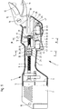
- the pruning shears shown in Figure 1 and designated 1 essentially consist of two mutually adjustable blades 11 and 12 projecting from a two-shell housing 2, of which the pawl 11 is rigidly connected to the housing 2 and the pawl 12 can be pivoted by means of an electric motor 5.
- the electric motor 5, which is powered by a battery 6, is connected to the pawl 12 via a reduction gear 7, a threaded spindle 8 and a spindle nut 21 displaceable by the latter and a linkage formed from levers 28, 29.
- the housing 2 consists of two plastic shells 3 and 4, each of which is provided with a recess 9 on the side opposite the electric motor 5, through which the pawls 11 and 12 protrude.
- the half-shells 3 and 4 are firmly connected to one another by means of screws 10.
- the pawl 11 is provided with an extension 13 projecting in the direction of the threaded spindle 8, which has bolts 14 penetrating through the holes is attached to the half-shell 4.
- the extension piece 13 has a bearing eye 15 in which the pawl 12 is held pivotably by means of a bolt 16.
- a recess 17 is also machined into the extension piece 13, and a roller bearing 31 is axially immovably arranged on the threaded spindle 8, which is supported in the recess 17 in the axial direction.
- the threaded spindle 8 is provided with a stepped bolt 32 onto which the roller bearing 31 is placed.
- a snap ring 33 held in the bolt 32 on the one hand and a stop surface 34 worked on the threaded spindle 8
- the roller bearing 8 is fixed thereon, and the mutually facing surfaces of the recess 17 are designed as contact surfaces 18 and 19 for the roller bearing 31. Forces acting on the threaded spindle 8 can thus be transmitted to the extension 13 via the roller bearing 31.
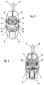
- the threaded nut 21 is guided by means of two laterally protruding bolts 24 and 25 in grooves 26 and 27 formed in the half-shells 3 and 4 of the housing 2 in a torsion-proof but axially displaceable manner.
- the levers 28 and 29 are operatively connected to the adjustable pawl 12 by means of a hinge pin 30.
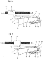
- the control switch 41 has, as can be seen in particular in FIG. 1 and FIGS. 4 to 9, two changeover switches 42 and 43, the adjusting elements 44 and 45 of which interact with a control link 51 which is attached to the threaded nut 21.
- the control link 51 is formed by a bar 52 which runs parallel to the threaded spindle 8 and into which a recess 53 which is open in the direction of the control switch 41 and whose side walls 54 and 55 are inclined to one another is incorporated.
- control switch 41 can be tilted about an axis directed perpendicularly to the threaded spindle 8 in the housing 2 against the force of a spring 47, which moves supported on the housing 2, supported, so that the electric motor 5 can be optionally controlled by means of the changeover switches 42 and 43 in cooperation with the link 51.
- control switch 41 is shown in a neutral position. If, starting from this neutral position, as shown in FIG. 4, pressure is exerted by hand on the control switch 41 and this is tilted around the bolt 46, the electric motor 5 is rotated in this way via the changeover switch 42, since its adjusting member 44 is actuated that the threaded nut 21 and thus also the levers 28, 29 are shifted to the left and the pawl 12 is pivoted in the direction of the pawl 11.
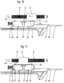
- the control link 51 and thus the bar 52 are also shifted to the left.
- the adjusting member 44 of the changeover switch 42 is inserted into the recess 53, as shown in FIG. 5, so that the changeover switch 42 is no longer actuated and the electric motor 5 is switched off automatically.
- the cutting process is thus ended and the pruning shear 1 is closed.
- control switch 41 can be locked in accordance with FIG. 8 and the pruning shears 1 can thus be kept closed.
- This can be accomplished by means of a slide 49 adjustably mounted on the housing 2, which has an open recess 50 assigned to a bolt 48 fastened to the control switch 41. If the slide 49 is moved, as shown in FIG. 8, the changeover switch 41 is connected via the slide 49 to the bolt 48 and thus firmly to the housing 2.
- control switch 41 When the control switch 41 is actuated, the spring 47 supported on this and the housing 2 was tensioned. If the control switch 41 is released from the operating position shown in FIG. 5 or the slide 49 is pushed back to the left, the control switch 41 is automatically tilted by the force of the tensioned spring 47 around the bolt 46 into the position shown in FIG. 6 . This means that the changeover switch 43, since its adjusting member 45 abuts the control link 51, is connected to the circuit of the electric motor 5 and this is reversed.
- the Threaded spindle 8 is rotated in this switching position of the control switch 41 in such a way that the threaded nut 41 and with it also the levers 28, 29 are shifted to the right, the blade 12 is thereby opened until the adjusting member 45 of the changeover switch 43 is over inclined side wall 55 is inserted into the recess 53 of the control link 51.
- the electric motor 5 is again stopped.
- the pawls 11 and 12 of the pruning shears 1 assume the open operating position.
- the threaded nut 21 can thus be shifted to the left to fully or partially open or to the right to completely or partially close the pruning shear 1 by the electric motor 5, but when the control switch 41 is released, the pruning shear 1 opens immediately automatically.
- the operating position of the pruning shears 1 can therefore be easily adapted to the work to be carried out or to the thickness of the branches to be cut, accidents and incorrect operations are thus avoided.
- control switch 61 provided with change-over switches 62 and 63 is slidably inserted in a recess 66 in the housing 2 of the pruning shears 1.
- the adjusting members 64 and 65 of the changeover switches 62 and 63 interact alternately with a control link 71 which is designed as a runner 72 provided with inclined surfaces 73 and 74 at the ends.
- a spring 77 which is supported on the housing 2 and acts in the longitudinal direction on the control switch 61, serves for the automatic return of the control switch 61.
- a neutral position is again shown in FIG. If the control switch 61 is moved to the left in accordance with FIG. 11, the changeover switch 63 is actuated and the threaded nut 21 is moved into the position shown in FIG. 11 in order to open the pruning shears 1.
- the electric motor 5 is driven via the changeover switch 62 in such a way that the threaded nut 21 is displaced by the threaded spindle 8 to the right into the position shown in FIG. 13 and the Pawls 11 and 12 of the pruning shears 1 are closed.
- the adjustment movement of the threaded nut 21 can also be interrupted at any time with the aid of the control switch 61, and the movement sequence can thus be stopped or vice versa.
- the spring 67 acting on the control switch 61 also ensures that the pruning shear 1 is automatically opened as soon as the control switch 61 is released.
Landscapes
- Life Sciences & Earth Sciences (AREA)
- Forests & Forestry (AREA)
- Biodiversity & Conservation Biology (AREA)
- Ecology (AREA)
- Environmental Sciences (AREA)
- Engineering & Computer Science (AREA)
- Mechanical Engineering (AREA)
- Scissors And Nippers (AREA)
- Shearing Machines (AREA)
Applications Claiming Priority (2)
| Application Number | Priority Date | Filing Date | Title |
|---|---|---|---|
| DE19616949A DE19616949C2 (de) | 1996-04-27 | 1996-04-27 | Elektromotrisch angetriebenes Schneidwerkzeug, insbesondere Astschere |
| DE19616949 | 1996-04-27 |
Publications (2)
| Publication Number | Publication Date |
|---|---|
| EP0803187A2 true EP0803187A2 (fr) | 1997-10-29 |
| EP0803187A3 EP0803187A3 (fr) | 1999-03-10 |
Family
ID=7792671
Family Applications (1)
| Application Number | Title | Priority Date | Filing Date |
|---|---|---|---|
| EP97101573A Withdrawn EP0803187A3 (fr) | 1996-04-27 | 1997-02-01 | Outil, en particulier élagueur |
Country Status (4)
| Country | Link |
|---|---|
| US (1) | US5867909A (fr) |
| EP (1) | EP0803187A3 (fr) |
| JP (1) | JPH1033850A (fr) |
| DE (1) | DE19616949C2 (fr) |
Cited By (16)
| Publication number | Priority date | Publication date | Assignee | Title |
|---|---|---|---|---|
| DE19815009A1 (de) * | 1998-04-03 | 1999-10-07 | Gardena Kress & Kastner Gmbh | Motorbetriebene Schere, insbesondere Astschere |
| WO2004082878A1 (fr) * | 2003-03-20 | 2004-09-30 | Nishida, Hiromi | Tete d'outil electrique et outil electrique associe |
| DE19849976B4 (de) * | 1997-10-30 | 2005-05-19 | Makita Corp., Anjo | Motorbetriebene Schere |
| EP2138030A1 (fr) * | 2008-06-23 | 2009-12-30 | Metabowerke Gmbh | Cisailles |
| EP2158803A1 (fr) | 2008-08-26 | 2010-03-03 | Robert Bosch GmbH | Outil de découpe de végétaux |
| EP2159529A1 (fr) | 2008-08-26 | 2010-03-03 | Robert Bosch GmbH | Mécanisme de commande d'interrupteur |
| EP2158805A1 (fr) | 2008-08-26 | 2010-03-03 | Robert Bosch GmbH | Outil de découpe de végétaux |
| EP2218323A1 (fr) * | 2009-02-13 | 2010-08-18 | Metabowerke GmbH | Sécateur |
| WO2010099762A1 (fr) * | 2009-03-06 | 2010-09-10 | 苏州宝时得电动工具有限公司 | Outil de coupe |
| EP2045050A4 (fr) * | 2006-07-20 | 2010-10-20 | Max Co Ltd | Ciseaux électriques |
| CN102577845A (zh) * | 2011-01-14 | 2012-07-18 | 苏州宝时得电动工具有限公司 | 剪枝机 |
| CN102848407A (zh) * | 2011-06-28 | 2013-01-02 | 美克司株式会社 | 电动剪刀 |
| EP2746002A1 (fr) * | 2012-12-19 | 2014-06-25 | Andreas Stihl AG & Co. KG | Ciseaux électriques |
| CN104303860A (zh) * | 2014-11-20 | 2015-01-28 | 柳州美纳机械有限公司 | 桑树伐条剪 |
| FR3028199A1 (fr) * | 2014-11-07 | 2016-05-13 | Innovation Fabrication Commercialisation Infaco | Outil motorise electroportatif a commande ergonomique. |
| US11950677B2 (en) | 2019-02-28 | 2024-04-09 | L'oreal | Devices and methods for electrostatic application of cosmetics |
Families Citing this family (43)
| Publication number | Priority date | Publication date | Assignee | Title |
|---|---|---|---|---|
| EP1064124B1 (fr) | 1998-02-16 | 2004-01-21 | Techtronic Industries Co., Ltd. | Appareil permettant de perforer les charpentes d'acier |
| JP4135294B2 (ja) * | 2000-03-31 | 2008-08-20 | 日立工機株式会社 | 電動往復動工具 |
| US6378217B1 (en) | 2000-07-06 | 2002-04-30 | One World Technologies, Inc. | Apparatus for punching steel studs and control circuit |
| JP2005052384A (ja) * | 2003-08-05 | 2005-03-03 | Kyameru Japan Kk | 電動鋏 |
| DE10353910A1 (de) * | 2003-11-18 | 2005-06-09 | Studiengesellschaft Kohle Mbh | Verfahren zur Synthese optisch aktiver Piperidine |
| US20050115081A1 (en) * | 2003-11-27 | 2005-06-02 | Shu-Woan Tu | Electric cutter |
| ES2245217B1 (es) * | 2004-03-04 | 2006-08-01 | Josep Gurri Molins | Util de corte portatil accionado mecanicamente. |
| AT501590B1 (de) * | 2005-11-25 | 2006-10-15 | Strube Karl | Elektrische schere |
| US20080010837A1 (en) * | 2006-07-12 | 2008-01-17 | William Weissenborn | Fluid-driven cutting device |
| USD559647S1 (en) * | 2006-08-23 | 2008-01-15 | Black & Decker Inc. | Power shears |
| EP2027767B1 (fr) * | 2007-08-22 | 2011-11-30 | Robert Bosch Gmbh | Appareil de découpage |
| FR2935175B1 (fr) * | 2008-08-22 | 2011-02-11 | Pellenc Sa | Dispositif permettant de determiner la position relative entre deux organes dont l'un au moins est mobile, et machines et appareils en faisant application |
| FR2935106B1 (fr) * | 2008-08-22 | 2010-09-17 | Pellenc Sa | Outil electroportatif a commande par gachette |
| CN101823265B (zh) * | 2009-03-06 | 2012-11-21 | 苏州宝时得电动工具有限公司 | 剪切刀具 |
| CN101876812B (zh) * | 2009-04-28 | 2012-07-04 | 南京德朔实业有限公司 | 电剪刀的控制方法 |
| CN201493868U (zh) * | 2009-09-08 | 2010-06-02 | 南京德朔实业有限公司 | 电动剪刀 |
| CN201563409U (zh) * | 2009-09-15 | 2010-09-01 | 南京德朔实业有限公司 | 电动剪刀 |
| US9339938B2 (en) | 2010-10-08 | 2016-05-17 | Milwaukee Electric Tool Corporation | Powered cutting tool |
| US8919787B1 (en) * | 2010-10-08 | 2014-12-30 | James Timothy Wilcher | Reciprocating tool attachment assembly and methods |
| USD657220S1 (en) * | 2010-10-13 | 2012-04-10 | Izumi Products Company | Electric cable cutter |
| USD657221S1 (en) * | 2010-10-13 | 2012-04-10 | Izumi Products Company | Electric cable cutter |
| CN103327806B (zh) * | 2010-12-30 | 2016-01-13 | 创科户外产品技术有限公司 | 电动修剪工具 |
| US9017147B2 (en) * | 2011-04-19 | 2015-04-28 | Siemens Energy, Inc. | Surface sample collection tool |
| JP5816492B2 (ja) * | 2011-09-01 | 2015-11-18 | 東神電気株式会社 | クランプ機構付き電線切断工具 |
| USD668922S1 (en) * | 2012-01-20 | 2012-10-16 | Milwaukee Electric Tool Corporation | Powered cutting tool |
| WO2013164310A1 (fr) * | 2012-05-04 | 2013-11-07 | Felco Motion Sa | Outil électroportatif |
| US9434013B2 (en) | 2012-12-13 | 2016-09-06 | Ingersoll-Rand Company | Sheet cutting shears |
| US10314228B2 (en) | 2014-05-16 | 2019-06-11 | Positec Power Tools (Suzhou) Co., Ltd. | Grass trimmer and cord delivering method of grass trimmer |
| US9675011B2 (en) * | 2014-10-28 | 2017-06-13 | Black & Decker Inc. | Shearing tool |
| CN105340593A (zh) * | 2015-11-19 | 2016-02-24 | 张莉萍 | 一种新型电动修枝剪刀 |
| US10471618B2 (en) | 2015-12-08 | 2019-11-12 | Milwaukee Electric Tool Corporation | Control of a cutting tool |
| US10507590B2 (en) | 2016-03-14 | 2019-12-17 | Milwaukee Electric Tool Corporation | Control of a cutting tool |
| MY195575A (en) * | 2016-11-04 | 2023-02-02 | Nagaki Seiki Kk | Cutting Tool |
| USD858237S1 (en) * | 2017-09-29 | 2019-09-03 | Izumi Products Company | Battery operated cutter |
| CN109168567B (zh) * | 2018-08-09 | 2021-08-03 | 吴依诺 | 一种林业清洁用修剪装置 |
| CN108971605B (zh) * | 2018-09-29 | 2020-09-04 | 嘉兴诺丁汉工业设计有限公司 | 一种用于抢险救灾的电动剪切器 |
| CN109392459A (zh) * | 2018-12-05 | 2019-03-01 | 凤台县年丰农业发展有限责任公司 | 一种效率高的葡萄采摘装置 |
| JP6695486B1 (ja) * | 2019-09-13 | 2020-05-20 | アルスコーポレーション株式会社 | 剪定用電動切断装置 |
| AU2021104983A4 (en) | 2020-09-10 | 2021-09-30 | Techtronic Cordless Gp | Blade replacement mechanism of electric instrument |
| US12202155B2 (en) | 2020-09-10 | 2025-01-21 | Techtronic Cordless Gp | Blade change mechanism for power tool |
| USD930449S1 (en) * | 2020-09-30 | 2021-09-14 | Wenwu Chen | Electric scissors |
| CN116456822B (zh) * | 2020-11-20 | 2024-04-09 | 胡斯华纳有限公司 | 切割工具 |
| US20240066729A1 (en) * | 2022-08-26 | 2024-02-29 | Techtronic Cordless Gp | Tool with selectively engagable tool head |
Citations (2)
| Publication number | Priority date | Publication date | Assignee | Title |
|---|---|---|---|---|
| EP0118350A1 (fr) | 1983-02-18 | 1984-09-12 | SOCIETE D'ETUDES ET DE RECHERCHES DE L'ECOLE NATIONALE SUPERIEURE D'ARTS ET METIERS en abrégé S E R A M | Sécateur à moteur électrique |
| EP0291431A1 (fr) | 1987-04-28 | 1988-11-17 | ETABLISSEMENTS PELLENC ET MOTTE (Société Anonyme) | Outil électrique portable à asservissement en position |
Family Cites Families (21)
| Publication number | Priority date | Publication date | Assignee | Title |
|---|---|---|---|---|
| US1642259A (en) * | 1926-06-30 | 1927-09-13 | Delbert F Morse | Motor-driven shears |
| US1662473A (en) * | 1927-03-05 | 1928-03-13 | American Steel & Wire Co | Shear |
| US1786625A (en) * | 1929-08-12 | 1930-12-30 | Linn Olaf B Lindstrom | Electric pruning device |
| US2075341A (en) * | 1934-09-10 | 1937-03-30 | John S Goodman | Pruning apparatus for trees and the like |
| US2286552A (en) * | 1941-04-26 | 1942-06-16 | Klose Milton | Motor driven grass shears |
| US2705858A (en) * | 1953-11-16 | 1955-04-12 | Russell L Marsh | Power shears |
| US3178816A (en) * | 1963-04-12 | 1965-04-20 | Arvin E Schmid | Power pruning shears |
| US3199193A (en) * | 1963-08-12 | 1965-08-10 | Viadimir S Norty | Power operated cutter |
| US3408875A (en) * | 1967-03-09 | 1968-11-05 | Briskman Arthur | Power-operated tool |
| US3536976A (en) * | 1967-03-09 | 1970-10-27 | Arthur Briskman | Power-driven electronically controlled tool |
| US3583067A (en) * | 1968-07-12 | 1971-06-08 | Arthur Briskman | Universal power-operated handtool |
| US3693254A (en) * | 1970-08-26 | 1972-09-26 | Albert R Salonen | Motorized shearing implement |
| US3768088A (en) * | 1971-11-05 | 1973-10-23 | G Risius | Trailer stand leg position indicator |
| FR2469112A1 (fr) * | 1979-11-13 | 1981-05-22 | Pellenc & Motte | Secateur hydraulique a asservissement en position |
| NZ208927A (en) * | 1983-07-26 | 1987-04-30 | Kazimir Stolfa | Power driven sheet metal shears; blade configuration allows cutting of left and right curves |
| DE8802877U1 (de) * | 1987-03-06 | 1988-05-11 | VA.RI.ME. S.r.l., Merone, Como | Motorisierte Schere mit autonomer Speisung |
| FR2635435A1 (fr) * | 1988-08-18 | 1990-02-23 | Grognu Ets | Secateur |
| US4967474A (en) * | 1990-03-26 | 1990-11-06 | Wells Andrew J | Hand-held power-operated shears |
| AU2232692A (en) * | 1992-07-01 | 1994-01-31 | Vladimir Stepanovich Smolin | Device for preparation of fuel-air mixture for internal combustion engine |
| DE9401672U1 (de) * | 1994-02-02 | 1994-03-31 | Galties, Wolfgang, 35287 Amöneburg | Astschere |
| US5642566A (en) * | 1996-06-01 | 1997-07-01 | Izumi Products Company | Electric powered cable cutter |
-
1996
- 1996-04-27 DE DE19616949A patent/DE19616949C2/de not_active Expired - Fee Related
-
1997
- 1997-02-01 EP EP97101573A patent/EP0803187A3/fr not_active Withdrawn
- 1997-04-23 US US08/842,002 patent/US5867909A/en not_active Expired - Fee Related
- 1997-04-24 JP JP9107496A patent/JPH1033850A/ja active Pending
Patent Citations (2)
| Publication number | Priority date | Publication date | Assignee | Title |
|---|---|---|---|---|
| EP0118350A1 (fr) | 1983-02-18 | 1984-09-12 | SOCIETE D'ETUDES ET DE RECHERCHES DE L'ECOLE NATIONALE SUPERIEURE D'ARTS ET METIERS en abrégé S E R A M | Sécateur à moteur électrique |
| EP0291431A1 (fr) | 1987-04-28 | 1988-11-17 | ETABLISSEMENTS PELLENC ET MOTTE (Société Anonyme) | Outil électrique portable à asservissement en position |
Cited By (19)
| Publication number | Priority date | Publication date | Assignee | Title |
|---|---|---|---|---|
| DE19849976B4 (de) * | 1997-10-30 | 2005-05-19 | Makita Corp., Anjo | Motorbetriebene Schere |
| DE19815009A1 (de) * | 1998-04-03 | 1999-10-07 | Gardena Kress & Kastner Gmbh | Motorbetriebene Schere, insbesondere Astschere |
| WO2004082878A1 (fr) * | 2003-03-20 | 2004-09-30 | Nishida, Hiromi | Tete d'outil electrique et outil electrique associe |
| US8122607B2 (en) | 2006-07-20 | 2012-02-28 | Max Co., Ltd. | Electric shears |
| EP2045050A4 (fr) * | 2006-07-20 | 2010-10-20 | Max Co Ltd | Ciseaux électriques |
| EP2138030A1 (fr) * | 2008-06-23 | 2009-12-30 | Metabowerke Gmbh | Cisailles |
| EP2158803A1 (fr) | 2008-08-26 | 2010-03-03 | Robert Bosch GmbH | Outil de découpe de végétaux |
| EP2159529A1 (fr) | 2008-08-26 | 2010-03-03 | Robert Bosch GmbH | Mécanisme de commande d'interrupteur |
| EP2158805A1 (fr) | 2008-08-26 | 2010-03-03 | Robert Bosch GmbH | Outil de découpe de végétaux |
| EP2218323A1 (fr) * | 2009-02-13 | 2010-08-18 | Metabowerke GmbH | Sécateur |
| WO2010099762A1 (fr) * | 2009-03-06 | 2010-09-10 | 苏州宝时得电动工具有限公司 | Outil de coupe |
| CN102577845A (zh) * | 2011-01-14 | 2012-07-18 | 苏州宝时得电动工具有限公司 | 剪枝机 |
| CN102848407A (zh) * | 2011-06-28 | 2013-01-02 | 美克司株式会社 | 电动剪刀 |
| US9120235B2 (en) | 2011-06-28 | 2015-09-01 | Max Co., Ltd. | Electric scissors |
| CN102848407B (zh) * | 2011-06-28 | 2016-06-22 | 美克司株式会社 | 电动剪刀 |
| EP2746002A1 (fr) * | 2012-12-19 | 2014-06-25 | Andreas Stihl AG & Co. KG | Ciseaux électriques |
| FR3028199A1 (fr) * | 2014-11-07 | 2016-05-13 | Innovation Fabrication Commercialisation Infaco | Outil motorise electroportatif a commande ergonomique. |
| CN104303860A (zh) * | 2014-11-20 | 2015-01-28 | 柳州美纳机械有限公司 | 桑树伐条剪 |
| US11950677B2 (en) | 2019-02-28 | 2024-04-09 | L'oreal | Devices and methods for electrostatic application of cosmetics |
Also Published As
| Publication number | Publication date |
|---|---|
| EP0803187A3 (fr) | 1999-03-10 |
| JPH1033850A (ja) | 1998-02-10 |
| DE19616949C2 (de) | 1998-04-09 |
| DE19616949A1 (de) | 1997-11-06 |
| US5867909A (en) | 1999-02-09 |
Similar Documents
| Publication | Publication Date | Title |
|---|---|---|
| DE19616949C2 (de) | Elektromotrisch angetriebenes Schneidwerkzeug, insbesondere Astschere | |
| DE19616948C1 (de) | Schneidwerkzeug, insbesondere Astschere | |
| EP2054195B1 (fr) | Pince avec axe d'articulation mobile contre la force d'un ressort | |
| DE60106085T2 (de) | Tragbare schere mit motorantrieb | |
| DE2362291C2 (de) | Sicherheitseinrichtung zum Verstellen einer zwischen einer Schließstellung und einer Öffnungsstellung gegen Federkraft verschwendbaren Sägeblattverkleidung | |
| DD202269A5 (de) | Vorrichtung zum spannen, verschliessen und abschneiden von kunststoffbaendern fuer packstueckumreifungen | |
| EP0723512B1 (fr) | Dispositif de tensionnement et de sertissage de rubans de cerclage | |
| CH658212A5 (de) | Schermaschine. | |
| EP1625784B1 (fr) | Outil de coupe manuel, en particulier un taille-haie ou sécateur | |
| EP1201194A2 (fr) | Pince coupante chirurgicale | |
| DE3132127C2 (de) | Zuschneidevorrichtung für Flachmaterial wie Stoffe, Folien und dergleichen | |
| DE60100298T2 (de) | Pflanzenschneidevorrichtung | |
| DE4117988A1 (de) | Elektrischer rasierapparat | |
| EP0452668A1 (fr) | Cisailles à main comportant un mécanisme à cliquet pour la coupe des matériaux en forme de barres | |
| EP3476205B1 (fr) | Cisailles à main, en particulier un sécateur, cisailles à haies et/ou de jardinage | |
| DE20205106U1 (de) | Garten- oder Baumschere | |
| DE3339591C2 (fr) | ||
| DE7635497U1 (de) | Heckenschere mit elektromotorischem Antrieb | |
| DE3424356A1 (de) | Sicherheitsvorrichtung, insbesondere fuer eine schere | |
| DE3314459C2 (de) | Siloblockschneider | |
| EP1524079A1 (fr) | Unité d'entraínement pour dispositifs de serrage | |
| DE20317950U1 (de) | Elektrische Bearbeitungsmaschine | |
| EP0767310A2 (fr) | Dispositif de manoeuvre hydraulique | |
| EP2138030B1 (fr) | Cisailles | |
| DE1507021B2 (de) | Elektromotorisch angetriebene heckenschere |
Legal Events
| Date | Code | Title | Description |
|---|---|---|---|
| PUAI | Public reference made under article 153(3) epc to a published international application that has entered the european phase |
Free format text: ORIGINAL CODE: 0009012 |
|
| AK | Designated contracting states |
Kind code of ref document: A2 Designated state(s): DE ES FR GB GR IT |
|
| PUAL | Search report despatched |
Free format text: ORIGINAL CODE: 0009013 |
|
| AK | Designated contracting states |
Kind code of ref document: A3 Designated state(s): DE ES FR GB GR IT |
|
| STAA | Information on the status of an ep patent application or granted ep patent |
Free format text: STATUS: THE APPLICATION IS DEEMED TO BE WITHDRAWN |
|
| 18D | Application deemed to be withdrawn |
Effective date: 19990913 |