EP0803187A2 - Tool, especially pruning tool - Google Patents
Tool, especially pruning tool Download PDFInfo
- Publication number
- EP0803187A2 EP0803187A2 EP97101573A EP97101573A EP0803187A2 EP 0803187 A2 EP0803187 A2 EP 0803187A2 EP 97101573 A EP97101573 A EP 97101573A EP 97101573 A EP97101573 A EP 97101573A EP 0803187 A2 EP0803187 A2 EP 0803187A2
- Authority
- EP
- European Patent Office
- Prior art keywords
- housing
- control switch
- tool according
- control
- electric motor
- Prior art date
- Legal status (The legal status is an assumption and is not a legal conclusion. Google has not performed a legal analysis and makes no representation as to the accuracy of the status listed.)
- Withdrawn
Links
- 238000013138 pruning Methods 0.000 title claims abstract description 26
- 238000005520 cutting process Methods 0.000 abstract description 10
- 238000006073 displacement reaction Methods 0.000 abstract 1
- 230000007935 neutral effect Effects 0.000 description 3
- 238000010276 construction Methods 0.000 description 2
- 230000006978 adaptation Effects 0.000 description 1
- 230000005540 biological transmission Effects 0.000 description 1
- 230000007257 malfunction Effects 0.000 description 1
- 230000000149 penetrating effect Effects 0.000 description 1
- 230000001960 triggered effect Effects 0.000 description 1
Images



Classifications
-
- A—HUMAN NECESSITIES
- A01—AGRICULTURE; FORESTRY; ANIMAL HUSBANDRY; HUNTING; TRAPPING; FISHING
- A01G—HORTICULTURE; CULTIVATION OF VEGETABLES, FLOWERS, RICE, FRUIT, VINES, HOPS OR SEAWEED; FORESTRY; WATERING
- A01G3/00—Cutting implements specially adapted for horticultural purposes; Delimbing standing trees
- A01G3/02—Secateurs; Flower or fruit shears
- A01G3/033—Secateurs; Flower or fruit shears having motor-driven blades
- A01G3/037—Secateurs; Flower or fruit shears having motor-driven blades the driving means being an electric motor
-
- B—PERFORMING OPERATIONS; TRANSPORTING
- B26—HAND CUTTING TOOLS; CUTTING; SEVERING
- B26B—HAND-HELD CUTTING TOOLS NOT OTHERWISE PROVIDED FOR
- B26B15/00—Hand-held shears with motor-driven blades
Definitions
- the invention relates to a tool, in particular pruning shears or the like, with two mutually adjustable pawls, of which one pawl rigidly connected to a housing and the other pawl by an electric motor arranged in the housing via a threaded spindle rotatable by the latter this arranged, rotatably supported threaded nut and a linkage connected to it is adjustable.
- EP 0 291 431-A1 discloses a pruning shear of this type.
- the translational movements of the spindle nut are limited here by an electrical or electronic stop device, which acts directly or indirectly on the electric motor.
- the actuator is firmly connected to the threaded spindle and thus follows their feed movements, so that it assumes different operating positions, and the electrical control arrangement has a movable magnetic control plunger, which is acted upon by the actuating member, and a sensor fixed in the vicinity of the magnetic control plunger on.
- simple handling is also not possible due to the changes in position of the actuating member.
- EP 0 118 350-A1 discloses secateurs in which the adjustable pawl is connected via a cable to a disk arranged on the output shaft of the drive motor.
- the disc is provided with a control cam, and a switch is also built into the housing, which can be actuated by the pivotable pawl, so that a reverse rotation of the electric motor is initiated immediately when the scissors are closed.
- the pawls can therefore not assume any intermediate positions, rather the pawls are delivered by the force of the drive motor and opened by the force of a spring.
- the force of the return spring must also be overcome in each case during a cutting process and this must be tensioned; the drive motor must therefore be equipped with a corresponding drive power.
- the return spring is a wearing part and can break, its force is sometimes not sufficient to open the scissors, especially in the case of thicker branches to be cut.
- the actuation and transmission elements provided with these scissors therefore do not allow optimal handling.
- the object of the invention is therefore to be able to control the electric motor provided in the tool of the aforementioned type in such a way that the adjustment movement of the adjustable pawl can be stopped in any opening area and possibly also reversed.
- the adjustment movement of the adjustable pawl should therefore be able to be controlled as desired, so that adaptation to the cutting operations to be carried out is possible at any time.
- the power of the drive motor should be fully usable both during a cutting process and when opening the shears, so that malfunctions are almost impossible even when cutting thick branches. With a simple structural design and easy handling, working with such a tool should be made easier.
- a control switch is provided for controlled actuation of the electric motor, which can be tilted about an axis running perpendicular to the threaded spindle in the housing or is displaceable to a limited extent in the longitudinal direction of the housing.
- which has two changeover switches arranged at a lateral distance from one another and switched on in the circuit of the electric motor, and that a control link is attached to the spindle nut, on which cooperating control cams are worked with the adjusting members of the changeover switch.
- control switch is automatically adjustable in switching positions against the force of a spring.
- control link attached to the spindle nut can be formed by a strip projecting axially parallel to the threaded spindle, into which a recess open in the direction of the tiltably mounted control switch, with preferably inclined side walls, is incorporated as a control curve, the lateral distance between the two Adjusting the change-over switch should be dimensioned larger than the length of the recess provided in the bar and the spring acting on the tiltably mounted control switch should be arranged at a distance from the bolt carrying it and should be supported on the housing.
- the control link attached to the spindle nut can consist of a skid which has inclined surfaces inclined in the direction of the control switch in the two end regions and forms the control cam with these.
- the distance between the two adjustment members of the change-over switch should be larger than the effective length of the runner and the springs acting on the displaceably mounted control switch should be arranged in its adjustment direction and supported on the housing.
- control switch in a switching position, preferably in the switching position assigned to the closed latches, by means of a slide or the like with a bolt attached to the housing.
- a tool in particular a pruning shear
- the control switch is released the pruning shears are always opened automatically, by the power of the electric motor, the risk of accidents is reduced, and it is almost impossible for the pawl to get caught in a branch and the pruning shears are not opened.
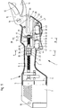
- the pruning shears shown in Figure 1 and designated 1 essentially consist of two mutually adjustable blades 11 and 12 projecting from a two-shell housing 2, of which the pawl 11 is rigidly connected to the housing 2 and the pawl 12 can be pivoted by means of an electric motor 5.
- the electric motor 5, which is powered by a battery 6, is connected to the pawl 12 via a reduction gear 7, a threaded spindle 8 and a spindle nut 21 displaceable by the latter and a linkage formed from levers 28, 29.
- the housing 2 consists of two plastic shells 3 and 4, each of which is provided with a recess 9 on the side opposite the electric motor 5, through which the pawls 11 and 12 protrude.
- the half-shells 3 and 4 are firmly connected to one another by means of screws 10.
- the pawl 11 is provided with an extension 13 projecting in the direction of the threaded spindle 8, which has bolts 14 penetrating through the holes is attached to the half-shell 4.
- the extension piece 13 has a bearing eye 15 in which the pawl 12 is held pivotably by means of a bolt 16.
- a recess 17 is also machined into the extension piece 13, and a roller bearing 31 is axially immovably arranged on the threaded spindle 8, which is supported in the recess 17 in the axial direction.
- the threaded spindle 8 is provided with a stepped bolt 32 onto which the roller bearing 31 is placed.
- a snap ring 33 held in the bolt 32 on the one hand and a stop surface 34 worked on the threaded spindle 8
- the roller bearing 8 is fixed thereon, and the mutually facing surfaces of the recess 17 are designed as contact surfaces 18 and 19 for the roller bearing 31. Forces acting on the threaded spindle 8 can thus be transmitted to the extension 13 via the roller bearing 31.
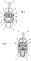
- the threaded nut 21 is guided by means of two laterally protruding bolts 24 and 25 in grooves 26 and 27 formed in the half-shells 3 and 4 of the housing 2 in a torsion-proof but axially displaceable manner.
- the levers 28 and 29 are operatively connected to the adjustable pawl 12 by means of a hinge pin 30.
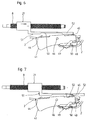
- the control switch 41 has, as can be seen in particular in FIG. 1 and FIGS. 4 to 9, two changeover switches 42 and 43, the adjusting elements 44 and 45 of which interact with a control link 51 which is attached to the threaded nut 21.
- the control link 51 is formed by a bar 52 which runs parallel to the threaded spindle 8 and into which a recess 53 which is open in the direction of the control switch 41 and whose side walls 54 and 55 are inclined to one another is incorporated.
- control switch 41 can be tilted about an axis directed perpendicularly to the threaded spindle 8 in the housing 2 against the force of a spring 47, which moves supported on the housing 2, supported, so that the electric motor 5 can be optionally controlled by means of the changeover switches 42 and 43 in cooperation with the link 51.
- control switch 41 is shown in a neutral position. If, starting from this neutral position, as shown in FIG. 4, pressure is exerted by hand on the control switch 41 and this is tilted around the bolt 46, the electric motor 5 is rotated in this way via the changeover switch 42, since its adjusting member 44 is actuated that the threaded nut 21 and thus also the levers 28, 29 are shifted to the left and the pawl 12 is pivoted in the direction of the pawl 11.
- the control link 51 and thus the bar 52 are also shifted to the left.
- the adjusting member 44 of the changeover switch 42 is inserted into the recess 53, as shown in FIG. 5, so that the changeover switch 42 is no longer actuated and the electric motor 5 is switched off automatically.
- the cutting process is thus ended and the pruning shear 1 is closed.
- control switch 41 can be locked in accordance with FIG. 8 and the pruning shears 1 can thus be kept closed.
- This can be accomplished by means of a slide 49 adjustably mounted on the housing 2, which has an open recess 50 assigned to a bolt 48 fastened to the control switch 41. If the slide 49 is moved, as shown in FIG. 8, the changeover switch 41 is connected via the slide 49 to the bolt 48 and thus firmly to the housing 2.
- control switch 41 When the control switch 41 is actuated, the spring 47 supported on this and the housing 2 was tensioned. If the control switch 41 is released from the operating position shown in FIG. 5 or the slide 49 is pushed back to the left, the control switch 41 is automatically tilted by the force of the tensioned spring 47 around the bolt 46 into the position shown in FIG. 6 . This means that the changeover switch 43, since its adjusting member 45 abuts the control link 51, is connected to the circuit of the electric motor 5 and this is reversed.
- the Threaded spindle 8 is rotated in this switching position of the control switch 41 in such a way that the threaded nut 41 and with it also the levers 28, 29 are shifted to the right, the blade 12 is thereby opened until the adjusting member 45 of the changeover switch 43 is over inclined side wall 55 is inserted into the recess 53 of the control link 51.
- the electric motor 5 is again stopped.
- the pawls 11 and 12 of the pruning shears 1 assume the open operating position.
- the threaded nut 21 can thus be shifted to the left to fully or partially open or to the right to completely or partially close the pruning shear 1 by the electric motor 5, but when the control switch 41 is released, the pruning shear 1 opens immediately automatically.
- the operating position of the pruning shears 1 can therefore be easily adapted to the work to be carried out or to the thickness of the branches to be cut, accidents and incorrect operations are thus avoided.
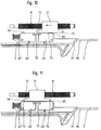
- control switch 61 provided with change-over switches 62 and 63 is slidably inserted in a recess 66 in the housing 2 of the pruning shears 1.
- the adjusting members 64 and 65 of the changeover switches 62 and 63 interact alternately with a control link 71 which is designed as a runner 72 provided with inclined surfaces 73 and 74 at the ends.
- a spring 77 which is supported on the housing 2 and acts in the longitudinal direction on the control switch 61, serves for the automatic return of the control switch 61.
- a neutral position is again shown in FIG. If the control switch 61 is moved to the left in accordance with FIG. 11, the changeover switch 63 is actuated and the threaded nut 21 is moved into the position shown in FIG. 11 in order to open the pruning shears 1.
- the electric motor 5 is driven via the changeover switch 62 in such a way that the threaded nut 21 is displaced by the threaded spindle 8 to the right into the position shown in FIG. 13 and the Pawls 11 and 12 of the pruning shears 1 are closed.
- the adjustment movement of the threaded nut 21 can also be interrupted at any time with the aid of the control switch 61, and the movement sequence can thus be stopped or vice versa.
- the spring 67 acting on the control switch 61 also ensures that the pruning shear 1 is automatically opened as soon as the control switch 61 is released.
Landscapes
- Life Sciences & Earth Sciences (AREA)
- Forests & Forestry (AREA)
- Biodiversity & Conservation Biology (AREA)
- Ecology (AREA)
- Environmental Sciences (AREA)
- Engineering & Computer Science (AREA)
- Mechanical Engineering (AREA)
- Scissors And Nippers (AREA)
- Shearing Machines (AREA)
Abstract
Description
Die Erfindung bezieht sich auf ein Werkzeug, insbesondere Astschere oder dgl., mit zwei gegeneinander verstellbaren Klinken, von denen die eine Klinke starr mit einem Gehäuse verbunden und die andere Klinke durch einen in dem Gehäuse angeordneten Elektromotor über eine von diesem verdrehbare Gewindespindel, einer auf dieser angeordneten, drehfest abgestützten Gewindemutter und einem mit dieser verbundenen Gestänge verstellbar ist.The invention relates to a tool, in particular pruning shears or the like, with two mutually adjustable pawls, of which one pawl rigidly connected to a housing and the other pawl by an electric motor arranged in the housing via a threaded spindle rotatable by the latter this arranged, rotatably supported threaded nut and a linkage connected to it is adjustable.
Durch die EP 0 291 431-A1 ist eine Astschere dieser Art bekannt. Die Translationsbewegungen der Spindelmutter sind hierbei durch eine elektrische oder elektronische Anschlagvorrichtung begrenzt, die unmittelbar oder mittelbar auf den Elektromotor einwirkt. Außerdem ist das Betätigungsorgan mit der Gewindespindel fest verbunden und folgt somit deren Vorschubbewegungen, so daß dieses unterschiedliche Betriebsstellungen einnimmt, und die elektrische Steueranordnung weist einen beweglichen magnetischen Steuerstößel, der durch das Betätigungsorgan beaufschlagt ist, sowie einen in der Nähe des magnetischen Steuerstößels fest fixierten Sensor auf. Abgesehen von dem erheblichen Bauaufwand, den diese Ausgestaltung erfordert, ist, auch bedingt durch die Lageänderungen des Betätigungsorgans, eine einfache Handhabung nicht gegeben.EP 0 291 431-A1 discloses a pruning shear of this type. The translational movements of the spindle nut are limited here by an electrical or electronic stop device, which acts directly or indirectly on the electric motor. In addition, the actuator is firmly connected to the threaded spindle and thus follows their feed movements, so that it assumes different operating positions, and the electrical control arrangement has a movable magnetic control plunger, which is acted upon by the actuating member, and a sensor fixed in the vicinity of the magnetic control plunger on. Apart from the considerable construction effort that this configuration requires, simple handling is also not possible due to the changes in position of the actuating member.
Des weiteren ist durch die EP 0 118 350-A1 eine Gartenschere bekannt, bei der die verstellbare Klinke über ein Kabel trieblich mit einer auf der Abtriebswelle des Antriebsmotors angeordneten Scheibe verbunden ist. Zum Abschalten des Elektromotors bei geöffnetem Schnittmesser ist die Scheibe mit einer Steuerkurve versehen, außerdem ist in dem Gehäuse ein Umschalter eingebaut, der durch die verschwenkbare Klinke betätigbar ist, so daß bei geschlossener Schere sofort eine Rückwärtsdrehung des Elektromotors eingeleitet wird. Die Klinken können somit keine Zwischenstellungen einnehmen, die Klinken werden vielmehr durch die Kraft des Antriebsmotors zugestellt und durch die Kraft einer Feder geöffnet. Auch ist bei einem Schneidevorgang jeweils die Kraft der Rückstellfeder zu überwinden und diese ist zu spannen, der Antriebsmotor ist daher mit einer entsprechenden Antriebsleistung auszustatten. Abgesehen davon, daß die Rückstellfeder ein Verschleißteil ist und brechen kann, ist deren Kraft mitunter, insbesondere bei dickeren abzuschneidenden Ästen zum Öffnen der Schere nicht ausreichend. Die bei dieser Schere vorgeseshene Betätigungs- und Übertragungsorgange ermöglichen somit keine optimale Handhabung.Furthermore, EP 0 118 350-A1 discloses secateurs in which the adjustable pawl is connected via a cable to a disk arranged on the output shaft of the drive motor. To switch off the electric motor when the cutting knife is open, the disc is provided with a control cam, and a switch is also built into the housing, which can be actuated by the pivotable pawl, so that a reverse rotation of the electric motor is initiated immediately when the scissors are closed. The pawls can therefore not assume any intermediate positions, rather the pawls are delivered by the force of the drive motor and opened by the force of a spring. The force of the return spring must also be overcome in each case during a cutting process and this must be tensioned; the drive motor must therefore be equipped with a corresponding drive power. Apart from the fact that the return spring is a wearing part and can break, its force is sometimes not sufficient to open the scissors, especially in the case of thicker branches to be cut. The actuation and transmission elements provided with these scissors therefore do not allow optimal handling.
Aufgabe der Erfindung ist es daher, den bei dem Werkzeug der vorgenannten Gattung vorgesehenen Elektromotor in der Weise steuern zu können, daß die Verstellbewegung der verstellbaren Klinke in jedem Öffnungsbereich angehalten und gegebenenfalls auch umgekehrt werden kann. Die Verstellbewegung der verstellbaren Klinke soll demnach beliebig gesteuert werden können, so daß jederzeit eine Anpassung an die vorzunehmenden Schnittvorgänge möglich ist. Außerdem soll die Kraft des Antriebsmotors sowohl bei einem Schneidevorgang als auch beim Öffnen der Schere voll nutzbar sein, so daß Betriebsstörungen selbst beim Durchtrennen dickerer Äste nahezu ausgeschlossen sind. Bei einfachem konstruktiven Aufbau und leichter Handhabung soll das Arbeiten mit einem solchen Werkzeug erleichtert werden.The object of the invention is therefore to be able to control the electric motor provided in the tool of the aforementioned type in such a way that the adjustment movement of the adjustable pawl can be stopped in any opening area and possibly also reversed. The adjustment movement of the adjustable pawl should therefore be able to be controlled as desired, so that adaptation to the cutting operations to be carried out is possible at any time. In addition, the power of the drive motor should be fully usable both during a cutting process and when opening the shears, so that malfunctions are almost impossible even when cutting thick branches. With a simple structural design and easy handling, working with such a tool should be made easier.
Gemäß der Erfindung wird dies bei einem Werkzeug, insbesondere einer Astschere der vorgenannten Ausgestaltung, dadurch erreicht, daß zur gesteuerten Betätigung des Elektromotors ein um eine senkrecht zu der Gewindespindel verlaufende Achse in dem Gehäuse kippbar oder in Längsrichtung des Gehäuses begrenzt verschiebbar gelagerter Steuerschalter vorgesehen ist, der zwei mit seitlichem Abstand zueinander angeordnete und in den Stromkreis des Elektromotors eingeschaltete Wechselschalter aufweist, und daß an der Spindelmutter eine Steuerkulisse angebracht ist, an der mit den Verstellgliedern der Wechselschalter zusammenwirkende Steuerkurven angearbeitet sind.According to the invention, this is achieved in a tool, in particular a pruning shear of the aforementioned configuration, in that a control switch is provided for controlled actuation of the electric motor, which can be tilted about an axis running perpendicular to the threaded spindle in the housing or is displaceable to a limited extent in the longitudinal direction of the housing. which has two changeover switches arranged at a lateral distance from one another and switched on in the circuit of the electric motor, and that a control link is attached to the spindle nut, on which cooperating control cams are worked with the adjusting members of the changeover switch.
Zweckmäßig ist es hierbei, wenn der Steuerschalter entgegen der Kraft einer Feder selbsttätig in Schaltpositionen verstellbar ist.It is expedient here if the control switch is automatically adjustable in switching positions against the force of a spring.
Nach einer bevorzugten Ausgestaltung kann die an der Spindelmutter angebrachte Steuerkulisse durch eine achsparallel zur Gewindespindel abstehende Leiste gebildet sein, in die eine in Richtung des kippbar gelagerten Steuerschalters offene Ausnehmung mit vorzugsweise zueinander geneigt verlaufenden Seitenwänden als Steuerkurve eingearbeitet ist, wobei der seitliche Abstand zwischen den beiden Verstellgliedern der Wechselschalter größer bemessen sein sollte als die Länge der in der Leiste vorgesehenen Ausnehmung und die auf den kippbar gelagerten Steuerschalter einwirkende Feder mit Abstand zu dem diesen tragenden Bolzen angeordnet und an dem Gehäuse abgestützt sein sollte.According to a preferred embodiment, the control link attached to the spindle nut can be formed by a strip projecting axially parallel to the threaded spindle, into which a recess open in the direction of the tiltably mounted control switch, with preferably inclined side walls, is incorporated as a control curve, the lateral distance between the two Adjusting the change-over switch should be dimensioned larger than the length of the recess provided in the bar and the spring acting on the tiltably mounted control switch should be arranged at a distance from the bolt carrying it and should be supported on the housing.
Nach einer andersartigen Ausführung kann die an der Spindelmutter angebrachte Steuerkulisse aus einer Kufe bestehen, die in den beiden Endbereichen in Richtung des Steuerschalters geneigte Schrägflächen aufweist und mit diesen die Steuerkurve bildet. Auch hierbei sollte der Abstand zwischen den beiden Verstellgliedern der Wechselschalter größer bemessen sein als die wirksame Länge der Kufe und die auf den verschiebbar gelagerten Steuerschalter einwirkende Federn sollte in dessen Verstellrichtung angeordnet und an dem Gehäuse abgestützt sein.According to a different design, the control link attached to the spindle nut can consist of a skid which has inclined surfaces inclined in the direction of the control switch in the two end regions and forms the control cam with these. Here, too, the distance between the two adjustment members of the change-over switch should be larger than the effective length of the runner and the springs acting on the displaceably mounted control switch should be arranged in its adjustment direction and supported on the housing.
Vorteilhaft ist es, zur Erhöhung der Betriebssicherheit ferner, den Steuerschalter in einer Schaltposition, vorzugsweise in der den geschlossenen Klinken zugeordneten Schaltposition, mittels eines Schiebers oder dgl. mit einem an dem Gehäuse angebrachten Bolzen fest zu verbinden.To increase operational safety, it is also advantageous to firmly connect the control switch in a switching position, preferably in the switching position assigned to the closed latches, by means of a slide or the like with a bolt attached to the housing.
Wird ein Werkzeug, insbesondere eine Astschere, gemäß der Erfindung ausgebildet, so ist es mit Hilfe des Steuerschalters auf einfache Weise möglich, die Verstellbewegung der verschwenkbar gelagerten Klinke jederzeit anzuhalten, fortzusetzen oder umzukehren, die Verstellbewegungen dieser Klinke sind somit beliebig steuerbar. Außerdem ist gewährleistet, daß beim Loslassen des Steuerschalters die Astschere stets selbsttätig geöffnet wird, und zwar durch die Kraft des Elektromotors, die Unfallgefahr wird dadurch reduziert, und es ist nahezu ausgeschlossen, daß sich die Klinke in einem Ast verhakt und die Schere nicht geöffnet wird.If a tool, in particular a pruning shear, is designed according to the invention, it is possible in a simple manner with the aid of the control switch to stop, continue or reverse the adjustment movement of the pivotably mounted pawl at any time, the adjustment movements of this pawl can thus be controlled as desired. Besides, is ensures that when the control switch is released the pruning shears are always opened automatically, by the power of the electric motor, the risk of accidents is reduced, and it is almost impossible for the pawl to get caught in a branch and the pruning shears are not opened.
Der Bauaufwand, mit dem dies zu bewerkstelligen ist, ist äußerst gering, da lediglich ein mit Wechselschaltern bestückter kippbar oder verschiebbar gelagerter Steuerschalter sowie eine Steuerkulisse vorzusehen sind, um die jeweils gewünschten Verstellbewegungen auszulösen. Fehlbetätigungen sind somit bei einfacher Handhabung des Steuerschalters zuverlässig vermieden, auch ist eine hohe Betriebssicherheit der vorschlagsgemäß ausgebildeten Astschere gegeben.The construction effort with which this can be accomplished is extremely low, since only a control switch equipped with toggle switches and tiltably or displaceably mounted and a control link are to be provided in order to trigger the respectively desired adjustment movements. Incorrect operations are thus reliably avoided with simple handling of the control switch, and there is also a high level of operational reliability of the pruning shears proposed.
In der Zeichnung ist ein Ausführungsbeispiel einer gemäß der Erfindung ausgebildeten Astschere dargestellt, das nachfolgend im einzelnen erläutert ist. Hierbei zeigt:
- Figur 1
- die Astschere, teilweise in einem Axialschnitt und teilweise in Ansicht,
Figur 2- einen Schnitt nach der Linie II - II der Figur 1,
Figur 3- einen Schnitt nach der Linie III - III der Figur ,
Figuren 4 bis 8- den bei der Astschere nach Figur 1 vorgesehenen Steuerschalter in unterschiedlichen Schaltpositionen und vereinfachter Darstellung
sowie Figuren 9 bis 13- einen verschiebbar gelagerten bei der Astschere nach Figur 1 verwendbaren Steuerschalter, ebenfalls in unterschiedlichen Schaltpositionen und vereinfachten Darstellungen.
- Figure 1
- the pruning shears, partly in an axial section and partly in view,
- Figure 2
- 2 shows a section along the line II-II of FIG. 1,
- Figure 3
- a section along the line III - III of the figure,
- Figures 4 to 8
- the control switch provided in the pruning shears according to Figure 1 in different switching positions and simplified representation
such as - Figures 9 to 13
- a slidably mounted control switch usable in the pruning shears according to Figure 1, also in different switching positions and simplified representations.
Die in Figur 1 dargestellte und mit 1 bezeichnete Astschere besteht im wesentlichen aus zwei aus einem zweischaligen Gehäuse 2 herausragende gegeneinander verstellbare Klingen 11 und 12, von denen die Klinke 11 starr mit dem Gehäuse 2 verbunden und die Klinke 12 mittels eines Elektromotors 5 verschwenkbar ist. Der von einer Batterie 6 gespeiste Elektromotor 5 ist dazu über ein Reduktionsgetriebe 7, eine Gewindespindel 8 sowie einer durch diese verschiebbaren Spindelmutter 21 und einem aus Hebeln 28, 29 gebildeten Gestänge trieblich mit der Klinke 12 verbunden.The pruning shears shown in Figure 1 and designated 1 essentially consist of two mutually
Das Gehäuse 2 besteht aus zwei Kunststoffschalen 3 und 4, die auf der dem Elektromotor 5 gegenüberliegenden Seite jeweils mit einer Freisparung 9 versehen sind, durch die die Klinken 11 und 12 herausragen. Mittels Schrauben 10 sind die Halbschalen 3 und 4 fest miteinander verbunden.The
Um die bei einem Schneidvorgang auftretenden Schnittkräfte innerhalb der daran beteiligten Bauteile abstützen zu können, so daß diese Kräfte nicht auf das Gehäuse 2 übertragen werden, ist die Klinke 11 mit einem in Richtung der Gewindespindel 8 abstehenden Ansatzstück 13 versehen, das mittels Bohrungen 14 durchgreifender Schrauben an der Halbschale 4 befestigt ist. Außerdem weist das Ansatzstück 13 ein Lagerauge 15 auf, in dem mittels eines Bolzens 16 die Klinke 12 verschwenkbar gehalten ist. Im Bereich der Gewindespindel 8 ist in das Ansatzstück 13 des weiteren eine Ausnehmung 17 eingearbeitet, und auf der Gewindespindel 8 ist ein Wälzlager 31 axial unverschiebbar angeordnet, das in der Ausnehmung 17 in Achsrichtung abgestützt ist. Die Gewindespindel 8 ist dazu mit einem abgesetzten Bolzen 32 versehen, auf den das Wälzlager 31 aufgesetzt ist. Mittels eines in dem Bolzen 32 gehaltenen Sprengringes 33 einerseits und einer an der Gewindespindel 8 angearbeiteten Anschlagfläche 34 ist das Wälzlager 8 auf dieser fixiert, außerdem sind die einander zugekehrten Flächen der Ausnehmung 17 als Anlageflächen 18 und 19 für das Wälzlager 31 ausgebildet. Auf die Gewindespindel 8 einwirkende Kräfte können somit über das Wälzlager 31 auf das Ansatzstück 13 übertragen werden.In order to be able to support the cutting forces occurring during a cutting process within the components involved, so that these forces are not transmitted to the
Die Gewindemutter 21 ist, wie dies insbesondere der Figur 2 zu entnehmen ist, mittels zweier seitlich abstehender Bolzen 24 und 25 in in die Halbschalen 3 und 4 des Gehäuses 2 eingeformter Nuten 26 und 27 verdrehfest aber axial verschiebbar geführt. Die Bolzen 24 und 25 stehen bei dem gezeigten Ausführungsbeispiel von Nocken 22 bzw. 23 ab, an denen die Hebel 28 und 29 mit einem Ende angelenkt sind, die dazu jeweils als mit Ausnehmungen 36 zur Aufnahme der Nocken 22 bzw. 23 versehene Laschen 35 ausgebildet sind. Mit dem anderen Ende sind die Hebel 28 und 29 mittels eines Gelenkbolzens 30 mit der verstellbaren Klinke 12 trieblich verbunden.The threaded
Wird mit Hilfe eines Steuerschalters 41 der Elektromotor 5 eingeschaltet und wird die Gewindespindel 8 durch diesen derart verdreht, daß die Gewindemutter 21 nach links verstellt wird, so wird über die mit dieser trieblich verbundenen Hebel 28 und 29 die Klinke 12 um den Bolzen 16 verschwenkt, so daß ein zwischen den Klinken 11 und 12 befindlicher Ast abgeschert wird. Durch eine Drehrichtungsumkehrung des Elektromotors 5 werden die Klinken 11 und 12 wiederum in die dargestellte Betriebsstellung zurückgeführt.If the electric motor 5 is switched on with the aid of a
Wird mit der Astschere 1 ein Teil durchtrennt, so ist dazu die Gewindemutter 21, um die Klinke 12 in Richtung der feststehenden Klinke 11 zu bewegen, durch die von dem Elektromotor 5 angetriebene Gewindespindel 8 nach links verschoben. Die dabei auftretende Zugkraft wird über das Wälzlager 31 an der Anlagefläche 19 abgestützt. Gleichzeitig wirkt auf das Ansatzstück 13 aber auch eine entgegengerichtete Kraft ein, die durch das Verschwenken der Klinke 12 ausgelöst und über den Bolzen 16 auf das Ansatzstück 13 übertragen wird. Und da diese Kräfte nahezu gleich groß, aber entgegengesetzt zueinander gerichtet sind, ist ein geschlossener Kraftfluß gegeben, so daß das Gehäuse 2 nahezu frei von durch einen Schnittvorgang bedingte Beanspruchungen ist.If a part is cut with the pruning shear 1, the threaded
Der Steuerschalter 41 weist, wie dies insbesondere der Figur 1 sowie den Figuren 4 bis 9 zu entnehmen ist, zwei Wechselschalter 42 und 43 auf, deren Verstellglieder 44 und 45 mit einer Steuerkulisse 51 zusammenwirken, die an der Gewindemutter 21 angebracht ist. Die Steuerkulisse 51 ist durch eine parallel zur Gewindespindel 8 verlaufende Leiste 52 gebildet, in die eine in Richtung des Steuerschalters 41 offene Ausnehmung 53 eingearbeitet ist, deren Seitenwände 54 und 55 zu einander geneigt verlaufen. Mittels eines Bolzens 46 ist der Steuerschalter 41 um eine senkrecht zu der Gewindespindel 8 gerichtete Achse kippbar in dem Gehäuse 2 entgegen der Kraft einer Feder 47, die sich an dem Gehäuse 2 abstützt, gelagert, so daß mittels der Wechselschalter 42 und 43 im Zusammenwirken mit der Kulisse 51 der Elektromotor 5 wahlweise gesteuert werden kann.The
In Figur 1 ist der Steuerschalter 41 in einer Neutralstellung dargestellt. Wird, ausgehend von dieser Neutralstellung, wie dies in Figur 4 gezeigt ist, von Hand Druck auf den Steuerschalter 41 ausgeübt und dieser um den Bolzen 46 gekippt, so wird über den Wechselschalter 42, da dessen Verstellglied 44 betätigt wird, der Elektromotor 5 derart verdreht, daß die Gewindemutter 21 und damit auch die Hebel 28, 29 nach links verschoben werden und die Klinke 12 in Richtung der Klinke 11 verschwenkt wird.In Figure 1, the
Zusammen mit der Gewindemutter 21 wird aber auch die Steuerkulisse 51 und somit die Leiste 52 nach links verschoben. Über die Seitenfläche 54 der Ausnehmung 53 wird somit, sobald die Steuerkulisse 51 eine entsprechende Lage erreicht, das Verstellglied 44 des Wechselschalters 42 in die Ausnehmung 53, wie dies in Figur 5 gezeigt ist, eingeführt, so daß der Wechselschalter 42 nicht mehr betätigt ist und der Elektromotor 5 selbsttätig ausgeschaltet wird. Der Schnittvorgang ist somit beendet und die Astschere 1 ist geschlossen.Together with the threaded
In dieser Betriebsstellung kann gemäß Figur 8 der Steuerschalter 41 arretiert und somit die Astschere 1 geschlossen gehalten werden. Dies ist mittels eines an dem Gehäuse 2 verstellbar angebrachten Schiebers 49 zu bewerkstelligen, der eine offene einem an dem Steuerschalter 41 befestigten Bolzen 48 zugeordnete Ausnehmung 50 aufweist. Wird der Schieber 49, wie in Figur 8 dargestellt, verschoben, ist der Umschalter 41 über den Schieber 49 mit dem Bolzen 48 und somit fest mit dem Gehäuse 2 verbunden.In this operating position, the
Beim Betätigen des Steuerschalters 41 wurde die an diesem und dem Gehäuse 2 abgestützte Feder 47 gespannt. Wird der Steuerschalter 41, ausgehend von der in Figur 5 gezeigten Betriebsstellung, losgelassen bzw. wird der Schieber 49 nach links zurückgeschoben, so wird der Steuerschalter 41 durch die Kraft der gespannten Feder 47 selbsttätig um den Bolzen 46 in die in Figur 6 dargestellte Lage gekippt. Dies bedeutet, daß der Wechselschalter 43, da dessen Verstellglied 45 an der Steuerkulisse 51 anliegt, an den Stromkreis des Elektromotors 5 angeschlossen ist und dieser umgepolt wird. Die Gewindespindel 8 wird in dieser Schaltposititon des Steuerschalters 41 derart verdreht daß die Gewindemutter 41 und mit dieser auch die Hebel 28, 29 nach rechts verschoben werden, die Klinge 12 wird dadurch geöffnet, und zwar so lange, bis das Verstellglied 45 des Wechselschalters 43 über die geneigte Seitenwand 55 in die Ausnehmung 53 der Steuerkulisse 51 eingeführt ist. In dieser in Figur 7 gezeigten Betriebsstellung wird der Elektromotor 5 wiederum stillgesetzt. Die Klinken 11 und 12 der Astschere 1 nehmen die geöffnete Betriebsstellung ein.When the
Durch wahlweises Betätigen der Wechselschalter 42 oder 43 kann somit die Gewindemutter 21 beliebig nach links zum vollständigen oder teilweisen Öffnen oder nach rechts zum vollständigen oder teilweisen Schließen der Astschere 1 durch den Elektromotor 5 verschoben werden, beim Loslassen des Steuerschalters 41 öffnet die Astschere 1 aber sofort selbsttätig. Die Betriebsstellung der Astschere 1 kann demnach problemlos an die jeweils vorzunehmenden Arbeiten bzw. an die Stärke der abzuschneidenden Äste angepaßt werden, Unfälle und Fehlbetätigungen werden somit vermieden.By optionally operating the change-
Bei der Ausgestaltung nach den Figuren 9 bis 13 ist der mit Wechselschaltern 62 und 63 versehene Steuerschalter 61 verschiebbar in einer Ausnehmung 66 des Gehäuses 2 der Astschere 1 eingesetzt. Die Verstellglieder 64 und 65 der Wechselschalter 62 und 63 wirken wechselweise mit einer Steuerkulisse 71 zusammen, die als an den Enden mit Schrägflächen 73 und 74 versehene Kufe 72 ausgebildet ist. Zur selbstätigen Rückführung des Steuerschalters 61 dient eine Feder 77, die an dem Gehäuse 2 abgestützt ist und in Längsrichtung auf den Steuerschalter 61 einwirkt.In the embodiment according to FIGS. 9 to 13, the
In Figur 10 ist wiederum eine Neutralstellung dargestellt. Wird der Steuerschalter 61 gemaß Figur 11 nach links verstellt, so wird der Wechselschalter 63 betätigt und die Gewindemutter 21 wird, um die Astschere 1 zu öffnen, in die in Figur 11 gezeigte Position verschoben. Durch Verschieben des Steuerschalters 61 nach rechts, wie dies der Figur 12 zu entnehmen ist, wird über den Wechselschalter 62 dagegen der Elektromotor 5 derart angetrieben, daß die Gewindemutter 21 durch die Gewindespindel 8 nach rechts bis in die in Figur 13 dargestellte Lage verschoben und die Klinken 11 und 12 der Astschere 1 geschlossen werden.A neutral position is again shown in FIG. If the
Selbstverständlich kann auch bei dieser Ausgestaltung mit Hilfe des Steuerschalters 61 die Verstellbewegung der Gewindemutter 21 jederzeit unterbrochen werden, der Bewegungsablauf somit stillgesetzt oder umgekehrt werden. Auch ist durch die auf den Steuerschalter 61 einwirkende Feder 67 gewährleistet, daß die Astschere 1, sobald der Steuerschalter 61 losgelassen wird, stets selbsttätig geöffnet wird.Of course, the adjustment movement of the threaded
Claims (9)
dadurch gekennzeichnet,
daß zur gesteuerten Betätigung des Elektromotors (5) ein um einen senkrecht zu der Gewindespindel (8) verlaufenden Bolzen (46) in dem Gehäuse (2) kippbar oder in Längsrichtung des Gehäuses (2) begrenzt verschiebbar gelagerter Steuerschalter (41; 61) vorgesehen ist, der zwei mit seitlichem Abstand zueinander angeordnete und in den Stromkreis des Elektromotors (5) eingeschaltete Wechselschalter (42, 43; 62, 63) aufweist, und daß an der Spindelmutter (21) eine Steuerkulisse (51; 71) angebracht ist, an der mit den Verstellgliedern (44, 45; 64, 65) der Wechselschalter (42, 43; 62, 63) zusammenwirkende Steuerkurven (53, 54, 55; 72, 73, 74) angearbeitet sind.Tool, in particular pruning shears (1) or the like, with two mutually adjustable pawls (11, 12), of which one pawl (11) rigidly connected to a housing (2) and the other pawl (12) by one in the housing (2) the electric motor (5) can be adjusted by means of a threaded spindle (8) which can be rotated by the latter, a threaded nut (21) supported on it in a rotationally fixed manner and a linkage (28, 29) connected to it,
characterized,
that for the controlled actuation of the electric motor (5) a control switch (41; 61) is provided which can be tilted in the housing (2) about a bolt (46) running perpendicular to the threaded spindle (8) or is displaceable to a limited extent in the longitudinal direction of the housing (2) , Which has two spaced-apart and in the circuit of the electric motor (5) switched toggle switch (42, 43; 62, 63), and that on the spindle nut (21) a control link (51; 71) is attached to the with the adjusting members (44, 45; 64, 65) of the changeover switches (42, 43; 62, 63) cooperating control cams (53, 54, 55; 72, 73, 74) are worked on.
dadurch gekennzeichnet,
daß der Steuerschalter (41; 61) entgegen der Kraft einer Feder (47; 67) selbsttätig in Schaltpositionen verstellbar ist.Tool according to claim 1,
characterized,
that the control switch (41; 61) against the force of a spring (47; 67) is automatically adjustable in switching positions.
dadurch gekennzeichnet,
daß die an der Spindelmutter (21) angebrachte Steuerkulisse (51) durch eine achsparallel zur Gewindespindel abstehende Leiste (52) gebildet ist, in die eine in Richtung des kippbar gelagerten Steuerschalters (41) offene Ausnehmung (53) mit vorzugsweise zueinander geneigt verlaufenden Seitenwänden (54, 55) als Steuerkurve eingearbeitt ist.Tool according to claim 1 or 2,
characterized,
that the control link (51) attached to the spindle nut (21) is formed by a bar (52) protruding axially parallel to the threaded spindle, into which a recess (53) which is open in the direction of the tiltably mounted control switch (41) and which preferably has inclined side walls ( 54, 55) is incorporated as a control curve.
dadurch gekennzeichnet,
daß der seitliche Abstand zwischen den beiden Verstellgliedern (44, 45) der Wechselschalter (42, 43) größer bemessen ist als die Länge der in der Leiste (52) vorgesehenen Ausnehmung (53).Tool according to claim 3,
characterized,
that the lateral distance between the two adjusting members (44, 45) of the changeover switches (42, 43) is larger than the length of the recess (53) provided in the bar (52).
dadurch gekennzeichnet,
daß die auf den kippbar gelagerten Steuerschalter (41) einwirkende Feder (47) mit Abstand zu den diesen tragenden Bolzen (46) angeordnet und an dem Gehäuse (2)abgestützt ist.Tool according to claim 3 or 4,
characterized,
that the spring (47) acting on the tiltably mounted control switch (41) is arranged at a distance from the bolts (46) carrying it and is supported on the housing (2).
dadurch gekennzeichnet,
daß die an der Spindelmutter (21) angebrachte Steuerkulisse (71) aus einer Kufe (72) besteht, die in den beiden Endbereichen in Richtung des Steuerschalters (61) geneigte Schrägflächen (73, 74) aufweist und mit diesen die Steuerkurve bildet.Tool according to claim 1 or 2,
characterized,
that the control link (71) attached to the spindle nut (21) consists of a runner (72) which has inclined surfaces (73, 74) inclined in the two end regions in the direction of the control switch (61) and forms the control cam with them.
dadurch gekennzeichnet,
daß der Abstand zwischen den beiden Verstellgliedern (64, 65) der Wechselschalter (62, 63) größer bemessen ist als die wirksame Länge der Kufe (62).Tool according to claim 6,
characterized,
that the distance between the two adjusting members (64, 65) of the changeover switch (62, 63) is larger than the effective length of the runner (62).
dadurch gekennzeichnet,
daß die auf den verschiebbar gelagerten Steuerschalter (61) einwirkende Feder (67) in dessen Verstellrichtung angeordnet und an dem Gehäuse (2) abgestützt ist.Tool according to claim 6 or 7,
characterized,
that the spring (67) acting on the displaceably mounted control switch (61) is arranged in its adjustment direction and is supported on the housing (2).
dadurch gekennzeichnet,
daß der Steuerschalter (41) in einer Schaltposition, vorzugsweise in der den geschlossenen Klinken (11, 12) zugeordneten Schaltposition, mittels eines Schiebers (49) oder dgl. mit einem an dem Gehäuse (2) angebrachten Bolzen (48) fest verbindbar ist.Tool according to one or more of claims 1 to 8,
characterized,
that the control switch (41) in a switching position, preferably in the switching position assigned to the closed latches (11, 12), can be firmly connected by means of a slide (49) or the like to a bolt (48) attached to the housing (2).
Applications Claiming Priority (2)
| Application Number | Priority Date | Filing Date | Title |
|---|---|---|---|
| DE19616949 | 1996-04-27 | ||
| DE19616949A DE19616949C2 (en) | 1996-04-27 | 1996-04-27 | Electromotically driven cutting tool, in particular pruning shears |
Publications (2)
| Publication Number | Publication Date |
|---|---|
| EP0803187A2 true EP0803187A2 (en) | 1997-10-29 |
| EP0803187A3 EP0803187A3 (en) | 1999-03-10 |
Family
ID=7792671
Family Applications (1)
| Application Number | Title | Priority Date | Filing Date |
|---|---|---|---|
| EP97101573A Withdrawn EP0803187A3 (en) | 1996-04-27 | 1997-02-01 | Tool, especially pruning tool |
Country Status (4)
| Country | Link |
|---|---|
| US (1) | US5867909A (en) |
| EP (1) | EP0803187A3 (en) |
| JP (1) | JPH1033850A (en) |
| DE (1) | DE19616949C2 (en) |
Cited By (16)
| Publication number | Priority date | Publication date | Assignee | Title |
|---|---|---|---|---|
| DE19815009A1 (en) * | 1998-04-03 | 1999-10-07 | Gardena Kress & Kastner Gmbh | Motor-operated shears such as branch cutters |
| WO2004082878A1 (en) * | 2003-03-20 | 2004-09-30 | Nishida, Hiromi | Power tool head and power tool |
| DE19849976B4 (en) * | 1997-10-30 | 2005-05-19 | Makita Corp., Anjo | Power operated scissors |
| EP2138030A1 (en) * | 2008-06-23 | 2009-12-30 | Metabowerke Gmbh | Branch shears |
| EP2158805A1 (en) | 2008-08-26 | 2010-03-03 | Robert Bosch GmbH | Vegetation cutting tool |
| EP2159529A1 (en) | 2008-08-26 | 2010-03-03 | Robert Bosch GmbH | Switch-operating mechanism |
| EP2158803A1 (en) | 2008-08-26 | 2010-03-03 | Robert Bosch GmbH | Vegetation cutting tool |
| EP2218323A1 (en) * | 2009-02-13 | 2010-08-18 | Metabowerke GmbH | Branch shears |
| WO2010099762A1 (en) * | 2009-03-06 | 2010-09-10 | 苏州宝时得电动工具有限公司 | Cutting tool |
| EP2045050A4 (en) * | 2006-07-20 | 2010-10-20 | Max Co Ltd | Electric scissors |
| CN102577845A (en) * | 2011-01-14 | 2012-07-18 | 苏州宝时得电动工具有限公司 | Tree trimmer |
| CN102848407A (en) * | 2011-06-28 | 2013-01-02 | 美克司株式会社 | Electric scissors |
| EP2746002A1 (en) * | 2012-12-19 | 2014-06-25 | Andreas Stihl AG & Co. KG | Electric cutter |
| CN104303860A (en) * | 2014-11-20 | 2015-01-28 | 柳州美纳机械有限公司 | Mulberry shoot cutting shears |
| FR3028199A1 (en) * | 2014-11-07 | 2016-05-13 | Innovation Fabrication Commercialisation Infaco | ELECTROPORTATIVE MOTORIZED TOOL WITH ERGONOMIC CONTROL. |
| US11950677B2 (en) | 2019-02-28 | 2024-04-09 | L'oreal | Devices and methods for electrostatic application of cosmetics |
Families Citing this family (44)
| Publication number | Priority date | Publication date | Assignee | Title |
|---|---|---|---|---|
| WO1999041046A1 (en) | 1998-02-16 | 1999-08-19 | Ryobi North America, Inc. | Apparatus for punching steel studs |
| JP4135294B2 (en) * | 2000-03-31 | 2008-08-20 | 日立工機株式会社 | Electric reciprocating tool |
| US6378217B1 (en) * | 2000-07-06 | 2002-04-30 | One World Technologies, Inc. | Apparatus for punching steel studs and control circuit |
| JP2005052384A (en) * | 2003-08-05 | 2005-03-03 | Kyameru Japan Kk | Electric scissors |
| DE10353910A1 (en) * | 2003-11-18 | 2005-06-09 | Studiengesellschaft Kohle Mbh | Process for the synthesis of optically active piperidines |
| US20050115081A1 (en) * | 2003-11-27 | 2005-06-02 | Shu-Woan Tu | Electric cutter |
| ES2245217B1 (en) * | 2004-03-04 | 2006-08-01 | Josep Gurri Molins | MECHANICALLY OPERATED PORTABLE CUTTING TOOL. |
| AT501590B1 (en) * | 2005-11-25 | 2006-10-15 | Strube Karl | ELECTRIC SCISSORS |
| US20080010837A1 (en) * | 2006-07-12 | 2008-01-17 | William Weissenborn | Fluid-driven cutting device |
| USD559647S1 (en) * | 2006-08-23 | 2008-01-15 | Black & Decker Inc. | Power shears |
| EP2027767B1 (en) * | 2007-08-22 | 2011-11-30 | Robert Bosch Gmbh | Cutting apparatus |
| FR2935106B1 (en) * | 2008-08-22 | 2010-09-17 | Pellenc Sa | PORTABLE ELECTROPORTATIVE TOOL |
| FR2935175B1 (en) * | 2008-08-22 | 2011-02-11 | Pellenc Sa | DEVICE FOR DETERMINING THE RELATIVE POSITION BETWEEN TWO OR MORE OF WHICH IS AT LEAST MOVABLE, AND MACHINES AND APPARATUSES BY APPLYING |
| CN101823265B (en) * | 2009-03-06 | 2012-11-21 | 苏州宝时得电动工具有限公司 | Shearing tool |
| CN101876812B (en) * | 2009-04-28 | 2012-07-04 | 南京德朔实业有限公司 | Control method of electric shears |
| CN201493868U (en) * | 2009-09-08 | 2010-06-02 | 南京德朔实业有限公司 | electric scissors |
| CN201563409U (en) * | 2009-09-15 | 2010-09-01 | 南京德朔实业有限公司 | Electric scissors |
| US8919787B1 (en) * | 2010-10-08 | 2014-12-30 | James Timothy Wilcher | Reciprocating tool attachment assembly and methods |
| US9339938B2 (en) | 2010-10-08 | 2016-05-17 | Milwaukee Electric Tool Corporation | Powered cutting tool |
| USD657220S1 (en) * | 2010-10-13 | 2012-04-10 | Izumi Products Company | Electric cable cutter |
| USD657221S1 (en) * | 2010-10-13 | 2012-04-10 | Izumi Products Company | Electric cable cutter |
| CN103327806B (en) * | 2010-12-30 | 2016-01-13 | 创科户外产品技术有限公司 | electric pruning tool |
| US9017147B2 (en) * | 2011-04-19 | 2015-04-28 | Siemens Energy, Inc. | Surface sample collection tool |
| JP5816492B2 (en) * | 2011-09-01 | 2015-11-18 | 東神電気株式会社 | Wire cutting tool with clamp mechanism |
| USD668922S1 (en) * | 2012-01-20 | 2012-10-16 | Milwaukee Electric Tool Corporation | Powered cutting tool |
| EP2844057B1 (en) * | 2012-05-04 | 2016-04-27 | FELCO Motion SA | Handheld power tool |
| US9434013B2 (en) | 2012-12-13 | 2016-09-06 | Ingersoll-Rand Company | Sheet cutting shears |
| US10314228B2 (en) * | 2014-05-16 | 2019-06-11 | Positec Power Tools (Suzhou) Co., Ltd. | Grass trimmer and cord delivering method of grass trimmer |
| US9675011B2 (en) * | 2014-10-28 | 2017-06-13 | Black & Decker Inc. | Shearing tool |
| CN105340593A (en) * | 2015-11-19 | 2016-02-24 | 张莉萍 | Novel electric pruning shears |
| US10471618B2 (en) | 2015-12-08 | 2019-11-12 | Milwaukee Electric Tool Corporation | Control of a cutting tool |
| US10507590B2 (en) * | 2016-03-14 | 2019-12-17 | Milwaukee Electric Tool Corporation | Control of a cutting tool |
| AU2016428531B2 (en) * | 2016-11-04 | 2020-03-05 | Nagaki Seiki Co., Ltd. | Cutting tool |
| USD858237S1 (en) * | 2017-09-29 | 2019-09-03 | Izumi Products Company | Battery operated cutter |
| CN109168567B (en) * | 2018-08-09 | 2021-08-03 | 吴依诺 | A pruning device for forestry cleaning |
| CN108971605B (en) * | 2018-09-29 | 2020-09-04 | 嘉兴诺丁汉工业设计有限公司 | Electric shears for emergency rescue and disaster relief |
| CN109392459A (en) * | 2018-12-05 | 2019-03-01 | 凤台县年丰农业发展有限责任公司 | A kind of high-efficient grape picker |
| JP6695486B1 (en) * | 2019-09-13 | 2020-05-20 | アルスコーポレーション株式会社 | Electric cutting device for pruning |
| AU2021104983A4 (en) | 2020-09-10 | 2021-09-30 | Techtronic Cordless Gp | Blade replacement mechanism of electric instrument |
| US12202155B2 (en) | 2020-09-10 | 2025-01-21 | Techtronic Cordless Gp | Blade change mechanism for power tool |
| USD930449S1 (en) * | 2020-09-30 | 2021-09-14 | Wenwu Chen | Electric scissors |
| EP4203668B1 (en) * | 2020-11-20 | 2024-02-21 | Husqvarna Ab | Cutting tool |
| WO2023150342A1 (en) * | 2022-02-07 | 2023-08-10 | Milwaukee Electric Tool Corporation | Battery powered metal snips |
| US20240066729A1 (en) * | 2022-08-26 | 2024-02-29 | Techtronic Cordless Gp | Tool with selectively engagable tool head |
Citations (2)
| Publication number | Priority date | Publication date | Assignee | Title |
|---|---|---|---|---|
| EP0118350A1 (en) | 1983-02-18 | 1984-09-12 | SOCIETE D'ETUDES ET DE RECHERCHES DE L'ECOLE NATIONALE SUPERIEURE D'ARTS ET METIERS en abrégé S E R A M | Electrically operated shears |
| EP0291431A1 (en) | 1987-04-28 | 1988-11-17 | ETABLISSEMENTS PELLENC ET MOTTE (Société Anonyme) | Portable electric tool with position control |
Family Cites Families (21)
| Publication number | Priority date | Publication date | Assignee | Title |
|---|---|---|---|---|
| US1642259A (en) * | 1926-06-30 | 1927-09-13 | Delbert F Morse | Motor-driven shears |
| US1662473A (en) * | 1927-03-05 | 1928-03-13 | American Steel & Wire Co | Shear |
| US1786625A (en) * | 1929-08-12 | 1930-12-30 | Linn Olaf B Lindstrom | Electric pruning device |
| US2075341A (en) * | 1934-09-10 | 1937-03-30 | John S Goodman | Pruning apparatus for trees and the like |
| US2286552A (en) * | 1941-04-26 | 1942-06-16 | Klose Milton | Motor driven grass shears |
| US2705858A (en) * | 1953-11-16 | 1955-04-12 | Russell L Marsh | Power shears |
| US3178816A (en) * | 1963-04-12 | 1965-04-20 | Arvin E Schmid | Power pruning shears |
| US3199193A (en) * | 1963-08-12 | 1965-08-10 | Viadimir S Norty | Power operated cutter |
| US3536976A (en) * | 1967-03-09 | 1970-10-27 | Arthur Briskman | Power-driven electronically controlled tool |
| US3408875A (en) * | 1967-03-09 | 1968-11-05 | Briskman Arthur | Power-operated tool |
| US3583067A (en) * | 1968-07-12 | 1971-06-08 | Arthur Briskman | Universal power-operated handtool |
| US3693254A (en) * | 1970-08-26 | 1972-09-26 | Albert R Salonen | Motorized shearing implement |
| US3768088A (en) * | 1971-11-05 | 1973-10-23 | G Risius | Trailer stand leg position indicator |
| FR2469112A1 (en) * | 1979-11-13 | 1981-05-22 | Pellenc & Motte | HYDRAULIC PRUNER WITH POSITION CONTROL |
| NZ208927A (en) * | 1983-07-26 | 1987-04-30 | Kazimir Stolfa | Power driven sheet metal shears; blade configuration allows cutting of left and right curves |
| DE8802877U1 (en) * | 1987-03-06 | 1988-05-11 | VA.RI.ME. S.r.l., Merone, Como | Motorized shears with autonomous power supply |
| FR2635435A1 (en) * | 1988-08-18 | 1990-02-23 | Grognu Ets | Secateurs |
| US4967474A (en) * | 1990-03-26 | 1990-11-06 | Wells Andrew J | Hand-held power-operated shears |
| WO1994001672A1 (en) * | 1992-07-01 | 1994-01-20 | Vladimir Stepanovich Smolin | Device for preparation of fuel-air mixture for internal combustion engine |
| DE9401672U1 (en) * | 1994-02-02 | 1994-03-31 | Galties, Wolfgang, 35287 Amöneburg | Pruning shears |
| US5642566A (en) * | 1996-06-01 | 1997-07-01 | Izumi Products Company | Electric powered cable cutter |
-
1996
- 1996-04-27 DE DE19616949A patent/DE19616949C2/en not_active Expired - Fee Related
-
1997
- 1997-02-01 EP EP97101573A patent/EP0803187A3/en not_active Withdrawn
- 1997-04-23 US US08/842,002 patent/US5867909A/en not_active Expired - Fee Related
- 1997-04-24 JP JP9107496A patent/JPH1033850A/en active Pending
Patent Citations (2)
| Publication number | Priority date | Publication date | Assignee | Title |
|---|---|---|---|---|
| EP0118350A1 (en) | 1983-02-18 | 1984-09-12 | SOCIETE D'ETUDES ET DE RECHERCHES DE L'ECOLE NATIONALE SUPERIEURE D'ARTS ET METIERS en abrégé S E R A M | Electrically operated shears |
| EP0291431A1 (en) | 1987-04-28 | 1988-11-17 | ETABLISSEMENTS PELLENC ET MOTTE (Société Anonyme) | Portable electric tool with position control |
Cited By (19)
| Publication number | Priority date | Publication date | Assignee | Title |
|---|---|---|---|---|
| DE19849976B4 (en) * | 1997-10-30 | 2005-05-19 | Makita Corp., Anjo | Power operated scissors |
| DE19815009A1 (en) * | 1998-04-03 | 1999-10-07 | Gardena Kress & Kastner Gmbh | Motor-operated shears such as branch cutters |
| WO2004082878A1 (en) * | 2003-03-20 | 2004-09-30 | Nishida, Hiromi | Power tool head and power tool |
| US8122607B2 (en) | 2006-07-20 | 2012-02-28 | Max Co., Ltd. | Electric shears |
| EP2045050A4 (en) * | 2006-07-20 | 2010-10-20 | Max Co Ltd | Electric scissors |
| EP2138030A1 (en) * | 2008-06-23 | 2009-12-30 | Metabowerke Gmbh | Branch shears |
| EP2158805A1 (en) | 2008-08-26 | 2010-03-03 | Robert Bosch GmbH | Vegetation cutting tool |
| EP2159529A1 (en) | 2008-08-26 | 2010-03-03 | Robert Bosch GmbH | Switch-operating mechanism |
| EP2158803A1 (en) | 2008-08-26 | 2010-03-03 | Robert Bosch GmbH | Vegetation cutting tool |
| EP2218323A1 (en) * | 2009-02-13 | 2010-08-18 | Metabowerke GmbH | Branch shears |
| WO2010099762A1 (en) * | 2009-03-06 | 2010-09-10 | 苏州宝时得电动工具有限公司 | Cutting tool |
| CN102577845A (en) * | 2011-01-14 | 2012-07-18 | 苏州宝时得电动工具有限公司 | Tree trimmer |
| CN102848407A (en) * | 2011-06-28 | 2013-01-02 | 美克司株式会社 | Electric scissors |
| US9120235B2 (en) | 2011-06-28 | 2015-09-01 | Max Co., Ltd. | Electric scissors |
| CN102848407B (en) * | 2011-06-28 | 2016-06-22 | 美克司株式会社 | Electric shear |
| EP2746002A1 (en) * | 2012-12-19 | 2014-06-25 | Andreas Stihl AG & Co. KG | Electric cutter |
| FR3028199A1 (en) * | 2014-11-07 | 2016-05-13 | Innovation Fabrication Commercialisation Infaco | ELECTROPORTATIVE MOTORIZED TOOL WITH ERGONOMIC CONTROL. |
| CN104303860A (en) * | 2014-11-20 | 2015-01-28 | 柳州美纳机械有限公司 | Mulberry shoot cutting shears |
| US11950677B2 (en) | 2019-02-28 | 2024-04-09 | L'oreal | Devices and methods for electrostatic application of cosmetics |
Also Published As
| Publication number | Publication date |
|---|---|
| JPH1033850A (en) | 1998-02-10 |
| DE19616949C2 (en) | 1998-04-09 |
| US5867909A (en) | 1999-02-09 |
| EP0803187A3 (en) | 1999-03-10 |
| DE19616949A1 (en) | 1997-11-06 |
Similar Documents
| Publication | Publication Date | Title |
|---|---|---|
| DE19616949C2 (en) | Electromotically driven cutting tool, in particular pruning shears | |
| DE19616948C1 (en) | Cutting tool, in particular pruning shears | |
| EP2054195B1 (en) | Pliers with joint pin that can be moved against the force of a spring | |
| DE60106085T2 (en) | PORTABLE SCISSORS WITH MOTOR DRIVE | |
| DE2362291C2 (en) | Safety device for adjusting a saw blade cover that can be wasted against spring force between a closed position and an open position | |
| DE19849976B4 (en) | Power operated scissors | |
| DD202269A5 (en) | DEVICE FOR TIGHTENING, CLOSING AND CUTTING PLASTIC PATCHES FOR PACKAGE ATTACHMENTS | |
| EP0723512B1 (en) | Device for tensioning packing straps and securing the ends together | |
| CH658212A5 (en) | SHEARING MACHINE. | |
| EP1625784B1 (en) | Manual cutting tool, particularly a hedge trimmer or pruning shears | |
| EP1201194A2 (en) | Surgical cutting pliers | |
| DE3132127C2 (en) | Cutting device for flat material such as fabrics, foils and the like | |
| DE60100298T2 (en) | A vegetation cutter | |
| DE2618717A1 (en) | MACHINE FOR FELLING AND TRIMMING TREES | |
| DE4117988A1 (en) | ELECTRIC SHAVER | |
| EP0452668A1 (en) | Hand shears with ratchet mechanism for cutting bar shaped materials | |
| EP3476205B1 (en) | Hand-shears, in particular pruning, hedge and/or garden shears | |
| DE20205106U1 (en) | Secateurs or secateurs | |
| DE7635497U1 (en) | Electric hedge trimmer | |
| DE3314459C2 (en) | Silo block cutter | |
| EP1524079A1 (en) | Drive unit for clamping devices | |
| DE20317950U1 (en) | A method for preventing the operation of an electric hand tool has a double locking system to prevent operation of the motor and also the rotation of the shaft | |
| EP0767310A2 (en) | Hydraulic actuator | |
| EP2138030B1 (en) | Branch shears | |
| DE1507021B2 (en) | ELECTRIC POWERED HEDGE SHEARS |
Legal Events
| Date | Code | Title | Description |
|---|---|---|---|
| PUAI | Public reference made under article 153(3) epc to a published international application that has entered the european phase |
Free format text: ORIGINAL CODE: 0009012 |
|
| AK | Designated contracting states |
Kind code of ref document: A2 Designated state(s): DE ES FR GB GR IT |
|
| PUAL | Search report despatched |
Free format text: ORIGINAL CODE: 0009013 |
|
| AK | Designated contracting states |
Kind code of ref document: A3 Designated state(s): DE ES FR GB GR IT |
|
| STAA | Information on the status of an ep patent application or granted ep patent |
Free format text: STATUS: THE APPLICATION IS DEEMED TO BE WITHDRAWN |
|
| 18D | Application deemed to be withdrawn |
Effective date: 19990913 |