EP0787642A2 - Verfahren und Vorrichtung zum Ausgleich von Drehmoment-Lenkeffekten - Google Patents
Verfahren und Vorrichtung zum Ausgleich von Drehmoment-Lenkeffekten Download PDFInfo
- Publication number
- EP0787642A2 EP0787642A2 EP96120210A EP96120210A EP0787642A2 EP 0787642 A2 EP0787642 A2 EP 0787642A2 EP 96120210 A EP96120210 A EP 96120210A EP 96120210 A EP96120210 A EP 96120210A EP 0787642 A2 EP0787642 A2 EP 0787642A2
- Authority
- EP
- European Patent Office
- Prior art keywords
- torque
- vehicle
- sensing
- steering
- steer
- Prior art date
- Legal status (The legal status is an assumption and is not a legal conclusion. Google has not performed a legal analysis and makes no representation as to the accuracy of the status listed.)
- Granted
Links
Images
Classifications
-
- B—PERFORMING OPERATIONS; TRANSPORTING
- B62—LAND VEHICLES FOR TRAVELLING OTHERWISE THAN ON RAILS
- B62D—MOTOR VEHICLES; TRAILERS
- B62D5/00—Power-assisted or power-driven steering
- B62D5/04—Power-assisted or power-driven steering electrical, e.g. using an electric servo-motor connected to, or forming part of, the steering gear
- B62D5/0457—Power-assisted or power-driven steering electrical, e.g. using an electric servo-motor connected to, or forming part of, the steering gear characterised by control features of the drive means as such
- B62D5/046—Controlling the motor
- B62D5/0472—Controlling the motor for damping vibrations
-
- B—PERFORMING OPERATIONS; TRANSPORTING
- B62—LAND VEHICLES FOR TRAVELLING OTHERWISE THAN ON RAILS
- B62D—MOTOR VEHICLES; TRAILERS
- B62D6/00—Arrangements for automatically controlling steering depending on driving conditions sensed and responded to, e.g. control circuits
- B62D6/002—Arrangements for automatically controlling steering depending on driving conditions sensed and responded to, e.g. control circuits computing target steering angles for front or rear wheels
Definitions
- the present invention is directed generally to controlling a vehicle power steering system and specifically directed to a method and apparatus for compensating torque steer in front wheel drive vehicles.
- Torque steer is a vehicle steering effect resulting from the torque developed by a vehicle engine.
- torque steer results when torque developed by the vehicle engine is transferred unevenly to the vehicle front wheels.
- torque steer is most easily understood by way of example. Assume a driver is travelling in a front wheel drive vehicle on a straight path down a straight road. If this driver suddenly accelerates, i.e., rapidly increases engine revolutions-per-minute ( RPMs ), the vehicle will tend to steer either left or right as a result of the torque steer effect on the vehicle. This situation thus requires the driver to compensate for the torque steer effect so as to maintain his correct path of travel down the road.
- RPMs revolutions-per-minute
- the present invention is directed to a method and apparatus for compensating for torque steer in front wheel drive vehicles and eliminate the need for driver interaction to correct for the effects of torque steer.
- an apparatus for compensating torque steer in a vehicle having a power assist steering system.
- the apparatus comprises means for sensing an operating characteristic of a vehicle indicative of torque steer.
- Means are provided for sensing an operator applied steering torque.
- the apparatus further includes control means for controlling the power assist steering system in response to the sensed operator applied steering torque and in response to the sensed torque steer characteristic so as to compensate for torque steer.
- the means for sensing an operating characteristic of a vehicle indicative of torque steer is engine speed or road wheel drive torque.
- a method for compensating torque steer in a vehicle power assist steering system.
- the method comprising the steps of sensing a vehicle operating characteristic indicative of torque steer, sensing applied steering torque by a vehicle operator, and controlling the power assist steering system in response to the sensed applied steering torque and the sensed operating characteristic indicative of torque steer so as to compensate for torque steer.
- the step of sensing an operating characteristic indicative of torque steer includes either the step of sensing rotations-per-minute of the vehicle engine or the step of sensing road wheel drive torque.
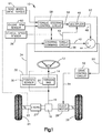
- a vehicle torque steer compensation system 10 in accordance with the present invention, includes a vehicle steering wheel 12 connected to an input shaft 14.
- a pinion gear 16 is connected to an output shaft 18.
- the input shaft 14 is coupled to the output shaft 18 through a torsion bar 20.
- the torsion bar 20 twists in response to torque applied to the vehicle steering wheel 12 and permits relative rotation between the input shaft 14 and the output shaft 18. Stops, not shown, limit the amount of relative rotation between the input shaft 14 and the output shaft 18 in a manner known in the art.
- the pinion gear 16 has helical gear teeth (not shown) which are meshingly engaged with straight cut gear teeth (not shown) on a linear steering member or rack 22.
- the rack 22 is coupled to vehicle steerable wheels 24 and 26 through steering linkage in a known manner.
- the pinion gear 16 together with the rack 22 forms a rack and pinion gear set.
- the vehicle's engine 27 is drivably coupled to the wheels 24, 26 in a known manner.
- the wheels 27, 26 are the front wheel drive vehicle.
- the present invention is also applicable to an all wheel drive vehicle.
- the rack and pinion gear set converts the rotary motion of the steering 22 moves linearly, the steerable wheels 24 and 26 pivot about their associated steering axes and the vehicle is steered.
- An electric assist motor 28 is drivingly connected with the rack 22 through, preferably, a ball-nut drive arrangement (not shown). The motor 28, when energized, provides power assist torque to aid a vehicle driver in steering movement of the rack 22 and, in turn, steering of the vehicle.
- a shaft position sensor 30 is operatively connected across the input shaft 14 and the output shaft 18.
- the shaft position sensor 30 provides an output signal on line 34 having a value indicative of the relative rotational position between the input shaft 14 and the output shaft 18. This relative rotational position between the input shaft 14 and the output shaft 18 is indicative of the steering torque applied by the vehicle operator to the vehicle steering wheel 12. Therefore, the value of the output signal on line 34 from the shaft position sensor 30 is indicative of the value or amount of steering torque applied to the vehicle steering wheel 12 and is referred to as the applied steering torque.
- the applied steering torque signal on line 34 is connected to a steering torque command circuit 36.
- the steering torque command circuit 36 determines the amount of desired assist torque to be provided by the motor 28 and provides a torque command output 40 having a value indicative of the determined amount of desired torque assist.
- the torque command output 40 is a function of two parameters: (i) the value of the applied steering torque; and (ii) vehicle speed.
- a vehicle speed sensor 38 provides a vehicle speed output signal to the torque command circuit 36 having a value indicative of the sensed vehicle speed.
- the amount of torque assist desired from the motor 28 decreases as vehicle speed increases. This is referred to in the art as "speed proportional steering.”
- the steering torque command circuit 36 provides a sign output 42 which has a sign value indicative of the direction the applied steering torque (i.e., left turn or right turn) indicated by the output on line 34 of the torque sensor 32.
- the operation of a torque command circuit, such as circuit 36, for control of an electric assist motor in response to applied steering torque and vehicle speed is known in the art and a detailed description of such operation is not discussed herein in detail.
- An example of a torque command circuit in accordance with the present invention is described in U.S. Patent No. 5,257,828 to Miller et al., which is hereby fully incorporated herein by reference.
- the output 40 of the steering torque command circuit 36 is connected to one input of a summing circuit 44.
- a multiplier circuit 46 provides a torque steer compensation output 48 which is connected to another input of the summing circuit 44.
- the summing circuit 44 provides a compensated torque command output 50 which is equal to the sum of the torque command value on output 40 and the torque steer compensation value on output 48.
- the value of the compensated torque command output 50 is the value of the assist torque needed to cause the motor 28 to: 1) provide the desired steering assist torque (output 40); and 2) compensate for the torque steer effect on the vehicle (output 48).
- the torque steer compensation output 48 is the value of the sign output 42 times the value of a torque steer output 56 provided by a torque steer control circuit 58.
- the torque steer control circuit 58 determines the value of the torque steer output 56 in response to: 1) vehicle speed sensed by the vehicle speed sensor 38; and 2) vehicle engine r.p.m. sensed by an engine r.p.m. sensor 60.
- the torque steer control circuit 58, along with the multiplier 46, summing circuit 44, and steering torque command circuit 36 are all programmed in a microcomputer controller 62.
- the engine speed is indicative of the amount of torque steer.
- a road wheel drive torque sensor 61 is operatively coupled between the vehicle engine 27 and the driven wheels 24, 26 preferably in the vehicle's transmission.
- the road wheel drive torque sensor provides an electrical signal to the torque steer control circuit 58 having a characteristic indicative of the drive torque being applied to the driven wheels 24, 26.
- the amount of the drive torque applied is indicative of the amount of the torque steer.
- the functional relationship between the value of the torque steer compensation output 56 and vehicle speed from sensor 38 and engine r.p.m. from sensor 60 or road wheel drive torque from sensor 61 is dependent upon the particular vehicle platform of interest. It is anticipated that each vehicle platform will have an associated functional relationship.
- the torque steer compensation functional relationship may be determined empirically and stored in the form of an internal look-up table (memory) in the microcomputer controller 62. Alternatively, the torque steer compensation functional relationship may be defined by an equation stored in the controller 62.
- the torque compensating output 50 provided by the summing circuit 44 is connected to a drive control circuit 52.
- the drive control circuit 52 uses the torque compensated output 50 in controlling the motor energization current and the motor direction.
- a motor drive output 54 is provided to the motor 28 to energize the motor 28 which causes the motor to develop the compensated torque assist, i.e., torque assist compensated for any sensed torque steer effect.
- the present invention has been described with regard to an electric power assist steering system, the invention is not limited to such a system.
- the present invention may be used with equal utility in a front wheel drive or all wheel drive vehicle having a hydraulic power steering system.
- hydraulic differential pressure is electrically controlled in response to measured engine r.p.m. or sensed road wheel drive torque to compensate for vehicle torque steer.
- Electric control of a hydraulic assist steering system is accomplished through electrical control of a valve between a pump and the hydraulic assist device.
- An apparatus for compensating for torque steer in a vehicle having a power assist steering system comprising:
Landscapes
- Engineering & Computer Science (AREA)
- Chemical & Material Sciences (AREA)
- Combustion & Propulsion (AREA)
- Transportation (AREA)
- Mechanical Engineering (AREA)
- Physics & Mathematics (AREA)
- Mathematical Physics (AREA)
- Steering Control In Accordance With Driving Conditions (AREA)
- Power Steering Mechanism (AREA)
Applications Claiming Priority (2)
| Application Number | Priority Date | Filing Date | Title |
|---|---|---|---|
| US594253 | 1996-01-30 | ||
| US08/594,253 US6032755A (en) | 1996-01-30 | 1996-01-30 | Method and apparatus for compensating torque steer |
Publications (3)
| Publication Number | Publication Date |
|---|---|
| EP0787642A2 true EP0787642A2 (de) | 1997-08-06 |
| EP0787642A3 EP0787642A3 (de) | 1998-08-19 |
| EP0787642B1 EP0787642B1 (de) | 2004-05-06 |
Family
ID=24378155
Family Applications (1)
| Application Number | Title | Priority Date | Filing Date |
|---|---|---|---|
| EP96120210A Expired - Lifetime EP0787642B1 (de) | 1996-01-30 | 1996-12-16 | Verfahren und Vorrichtung zum Ausgleich von Drehmoment-Lenkeffekten |
Country Status (5)
| Country | Link |
|---|---|
| US (1) | US6032755A (de) |
| EP (1) | EP0787642B1 (de) |
| JP (1) | JPH09207802A (de) |
| BR (1) | BR9700755A (de) |
| DE (1) | DE69632387T2 (de) |
Cited By (8)
| Publication number | Priority date | Publication date | Assignee | Title |
|---|---|---|---|---|
| FR2801270A1 (fr) * | 1999-11-23 | 2001-05-25 | Renault | Systeme de correction automatique de la trajectoire d'un vehicule |
| FR2835232A1 (fr) * | 2002-01-31 | 2003-08-01 | Koyo Seiko Co | Dispositif de correction de couple d'auto-alignement pour un vehicule et dispositif de direction assistee electrique |
| WO2004012978A1 (de) * | 2002-07-31 | 2004-02-12 | Daimlerchrysler Ag | Verfahren zur bestimmung eines bei einer betätigung eines lenkrades wirkenden lenkmoments bei kraftfahrzeugen |
| EP1031493A4 (de) * | 1997-11-12 | 2004-05-12 | Koyo Seiko Co | Steuerungssystem für fahrzeuge |
| EP1767437A1 (de) * | 2005-09-22 | 2007-03-28 | Volkswagen Aktiengesellschaft | Einrichtung zum Kompensieren von Schiefzieheffekten an einem Kraftfahrzeug |
| US7433768B2 (en) | 2002-07-31 | 2008-10-07 | Daimler Ag | Method for determining a steering-wheel torque |
| EP1800994B1 (de) * | 2004-10-14 | 2012-03-28 | Toyota Jidosha Kabushiki Kaisha | Steuerung für elektrische servolenkvorrichtung für ein fahrzeug, bei dem gelenkte räder angetrieben werden |
| DE102013220632A1 (de) | 2013-10-14 | 2015-04-16 | Volkswagen Aktiengesellschaft | Einrichtung mit einer Gelenkwellenanordnung sowie ein Antriebsstrang mit Gelenkwellen unterschiedlicher Länge |
Families Citing this family (27)
| Publication number | Priority date | Publication date | Assignee | Title |
|---|---|---|---|---|
| JP3517863B2 (ja) * | 1997-02-07 | 2004-04-12 | トヨタ自動車株式会社 | 操舵制御装置 |
| JP3649312B2 (ja) * | 1997-09-13 | 2005-05-18 | 本田技研工業株式会社 | ハイブリッド車の駆動力伝達装置 |
| JP3105847B2 (ja) * | 1997-11-04 | 2000-11-06 | 本田技研工業株式会社 | 電動操舵車両の操向輪制御構造 |
| JP3853943B2 (ja) * | 1997-11-12 | 2006-12-06 | 株式会社ジェイテクト | 車両のステアリング装置 |
| JP3344463B2 (ja) * | 1998-04-27 | 2002-11-11 | トヨタ自動車株式会社 | 車両用操舵制御装置 |
| US6661191B2 (en) | 2002-01-30 | 2003-12-09 | Visteon Global Technologies, Inc. | Method and apparatus for compensating drive current for an electric motor vehicle steering system |
| US7272478B2 (en) * | 2003-02-26 | 2007-09-18 | General Motors Corporation | Control system for active attenuation of torque-steer via electric power steering |
| US6868934B2 (en) * | 2003-07-09 | 2005-03-22 | Honda Giken Kogyo Kabushiki Kaisha | Variable power steering assist using driver grip pressure |
| JP4400270B2 (ja) * | 2004-03-19 | 2010-01-20 | 日産自動車株式会社 | 車両の舵角比制御装置 |
| US7532966B2 (en) * | 2004-08-20 | 2009-05-12 | General Motors Corporation | Torque steer compensation algorithm |
| JP4639769B2 (ja) * | 2004-11-18 | 2011-02-23 | 日産自動車株式会社 | 車両のトルクステア抑制構造 |
| DE102005007307A1 (de) * | 2005-02-16 | 2006-08-17 | Zf Lenksysteme Gmbh | Lenkung |
| JP2006273266A (ja) * | 2005-03-30 | 2006-10-12 | Denso Corp | 乗員保護装置 |
| JP4810965B2 (ja) * | 2005-10-19 | 2011-11-09 | トヨタ自動車株式会社 | 左右輪の駆動トルク差による車輌偏向を抑制した車輌 |
| DE102005057938A1 (de) * | 2005-12-05 | 2007-06-06 | Zf Lenksysteme Gmbh | Verfahren zum Betreiben einer Hilfskraftlenkung |
| JP4108713B2 (ja) * | 2006-03-17 | 2008-06-25 | 三菱電機株式会社 | 電動式パワーステアリング制御装置 |
| DE102006015636B4 (de) * | 2006-04-04 | 2011-04-28 | Volkswagen Ag | Verfahren zum Kompensieren von Schiefzieheffekten an einem Kraftfahrzeug über die Fahrzeuglenkung sowie hierzu geeignete Vorrichtung |
| US7970513B2 (en) * | 2006-06-15 | 2011-06-28 | Advics Co., Ltd. | Steering control apparatus for a vehicle |
| JP4835986B2 (ja) * | 2006-06-15 | 2011-12-14 | 株式会社アドヴィックス | 電動ステアリング制御装置 |
| DE102006044088B4 (de) * | 2006-09-20 | 2009-09-24 | Ford Global Technologies, LLC, Dearborn | Verfahren zum Ausgleich von Antriebseinflüssen eines Antriebsstranges eines Kraftfahrzeuges |
| DE102007001638A1 (de) | 2007-01-11 | 2008-07-17 | Zf Lenksysteme Gmbh | Verfahren zum Betreiben einer Hilfskraftlenkung |
| DE102007055773A1 (de) | 2007-12-12 | 2009-06-18 | Zf Lenksysteme Gmbh | Verfahren für den Betrieb einer elektrischen Hilfskraftlenkung |
| JP2010254030A (ja) * | 2009-04-22 | 2010-11-11 | Jtekt Corp | パワーステアリング装置 |
| US8682532B2 (en) | 2011-07-22 | 2014-03-25 | Honda Motor Co., Ltd. | Vehicle including friction control device and methods |
| US10053109B2 (en) | 2016-02-26 | 2018-08-21 | Honda Motor Co., Ltd. | Systems and methods for controlling a vehicle including friction control device |
| DE102018210388A1 (de) | 2018-06-26 | 2020-01-02 | Bayerische Motoren Werke Aktiengesellschaft | Verfahren zur Steuerung und/oder Regelung eines Lenksystems eines Kraftfahrzeuges |
| JP7400686B2 (ja) * | 2020-10-13 | 2023-12-19 | 株式会社デンソー | 車両転舵装置 |
Family Cites Families (17)
| Publication number | Priority date | Publication date | Assignee | Title |
|---|---|---|---|---|
| KR920007039B1 (ko) * | 1985-02-02 | 1992-08-24 | 가부시기가이샤 히다찌세이사꾸쇼 | 전동 파워스티어링장치 |
| JPH07100450B2 (ja) * | 1985-11-08 | 1995-11-01 | 自動車機器株式会社 | 動力舵取装置の制御装置 |
| DE3680508D1 (de) * | 1985-12-27 | 1991-08-29 | Aisin Warner | Steuereinrichtung fuer ein vierradgetriebenes fahrzeug mit mittendifferential. |
| JPH0665550B2 (ja) * | 1986-01-08 | 1994-08-24 | 株式会社日立製作所 | パワ−ステアリング制御装置 |
| JPS62182873A (ja) * | 1986-02-05 | 1987-08-11 | Shin Nikkei Co Ltd | 建具作図システム |
| JPH0288362A (ja) * | 1988-09-26 | 1990-03-28 | Mitsubishi Electric Corp | パワーステアリング装置 |
| JPH07108665B2 (ja) * | 1988-11-14 | 1995-11-22 | 自動車機器株式会社 | 動力舵取装置の制御方法 |
| US5291962A (en) * | 1989-11-07 | 1994-03-08 | Hino Jidosha Kogyo Kabushiki Kaisha | Power steering device for use in motor vehicles |
| JP2969874B2 (ja) * | 1990-09-17 | 1999-11-02 | 日産自動車株式会社 | 舵角制御装置 |
| JP3046108B2 (ja) * | 1991-08-26 | 2000-05-29 | 富士重工業株式会社 | 差動制限装置付き車両の舵力制御方法 |
| EP0536590B1 (de) * | 1991-10-10 | 1995-05-24 | Koyo Seiko Co., Ltd. | Elektrische Servolenkung |
| US5528497A (en) * | 1992-09-16 | 1996-06-18 | Honda Giken Kogyo Kabushiki Kaisha | Vehicle steering control system |
| JP3182472B2 (ja) * | 1993-06-10 | 2001-07-03 | 本田技研工業株式会社 | パワーステアリング装置 |
| US5417298A (en) * | 1993-07-07 | 1995-05-23 | Honda Giken Kohyo Kabushiki Kaisha | Torque distribution control apparatus for vehicle |
| JP3034430B2 (ja) * | 1994-07-27 | 2000-04-17 | 本田技研工業株式会社 | 車両用操舵装置の操舵反力制御装置 |
| JP3095961B2 (ja) * | 1994-10-04 | 2000-10-10 | 本田技研工業株式会社 | 車両用操舵装置の操舵反力制御装置 |
| US5623409A (en) * | 1994-10-31 | 1997-04-22 | Trw Inc. | Method and apparatus for non-linear damping of an electric assist steering system for vehicle yaw rate control |
-
1996
- 1996-01-30 US US08/594,253 patent/US6032755A/en not_active Expired - Lifetime
- 1996-12-16 EP EP96120210A patent/EP0787642B1/de not_active Expired - Lifetime
- 1996-12-16 DE DE69632387T patent/DE69632387T2/de not_active Expired - Lifetime
-
1997
- 1997-01-23 BR BR9700755A patent/BR9700755A/pt not_active IP Right Cessation
- 1997-01-30 JP JP9016624A patent/JPH09207802A/ja active Pending
Cited By (9)
| Publication number | Priority date | Publication date | Assignee | Title |
|---|---|---|---|---|
| EP1031493A4 (de) * | 1997-11-12 | 2004-05-12 | Koyo Seiko Co | Steuerungssystem für fahrzeuge |
| FR2801270A1 (fr) * | 1999-11-23 | 2001-05-25 | Renault | Systeme de correction automatique de la trajectoire d'un vehicule |
| FR2835232A1 (fr) * | 2002-01-31 | 2003-08-01 | Koyo Seiko Co | Dispositif de correction de couple d'auto-alignement pour un vehicule et dispositif de direction assistee electrique |
| WO2004012978A1 (de) * | 2002-07-31 | 2004-02-12 | Daimlerchrysler Ag | Verfahren zur bestimmung eines bei einer betätigung eines lenkrades wirkenden lenkmoments bei kraftfahrzeugen |
| US7433768B2 (en) | 2002-07-31 | 2008-10-07 | Daimler Ag | Method for determining a steering-wheel torque |
| EP1800994B1 (de) * | 2004-10-14 | 2012-03-28 | Toyota Jidosha Kabushiki Kaisha | Steuerung für elektrische servolenkvorrichtung für ein fahrzeug, bei dem gelenkte räder angetrieben werden |
| EP1767437A1 (de) * | 2005-09-22 | 2007-03-28 | Volkswagen Aktiengesellschaft | Einrichtung zum Kompensieren von Schiefzieheffekten an einem Kraftfahrzeug |
| DE102013220632A1 (de) | 2013-10-14 | 2015-04-16 | Volkswagen Aktiengesellschaft | Einrichtung mit einer Gelenkwellenanordnung sowie ein Antriebsstrang mit Gelenkwellen unterschiedlicher Länge |
| DE102013220632B4 (de) | 2013-10-14 | 2018-04-26 | Volkswagen Aktiengesellschaft | Einrichtung mit einer Gelenkwellenanordnung sowie ein Antriebsstrang mit Gelenkwellen unterschiedlicher Länge |
Also Published As
| Publication number | Publication date |
|---|---|
| EP0787642A3 (de) | 1998-08-19 |
| DE69632387D1 (de) | 2004-06-09 |
| JPH09207802A (ja) | 1997-08-12 |
| DE69632387T2 (de) | 2005-05-04 |
| US6032755A (en) | 2000-03-07 |
| BR9700755A (pt) | 1998-11-10 |
| EP0787642B1 (de) | 2004-05-06 |
Similar Documents
| Publication | Publication Date | Title |
|---|---|---|
| US6032755A (en) | Method and apparatus for compensating torque steer | |
| EP0596167B1 (de) | System mit variablem Lenkverhältnis für ein Kraftfahrzeug | |
| EP0190678B1 (de) | Elektromotorisches Servolenkverfahren und System | |
| US4834203A (en) | Electric power steering system | |
| US6782968B2 (en) | Automatic steering apparatus for vehicle and control method of same | |
| US4909343A (en) | Electric power steering system | |
| US7792619B2 (en) | Electrically driven power steering system for vehicle | |
| EP1304276B1 (de) | Verfahren und Vorrichtung zum Steuern des Lenkverhältnisses | |
| US5398953A (en) | Electrically operated power steering system | |
| JP4275752B2 (ja) | 自動車用操舵装置 | |
| EP0490673B1 (de) | Lenkeinrichtung eines Förderfahrzeuges | |
| US6112845A (en) | Reactive steering control system | |
| EP0671310A1 (de) | Verfahren und Vorrichtung zur Steuerung eines elektrischen Hilfslinkkraftsystems | |
| EP0775624A2 (de) | Lenksystem für ein Kraftfahrzeug | |
| EP0779199B1 (de) | Lenkungssteuerung mit Lenkdrehmoment-Hysterese | |
| EP1125822B1 (de) | Elektrisches Servolenkungssytem für ein Fahrzeug und Verfahren auf Basis von Drehwinkel zur Drehmomentschätzung | |
| EP0810142A3 (de) | Von einem Motor angetriebene Servolenkung für ein Kraftfahrzeug | |
| US20010001842A1 (en) | Reverse determination method of vehicle and vehicle control apparatus | |
| US4875541A (en) | Electric power steering system | |
| US6072293A (en) | Steering control system for vehicle | |
| EP0164842A2 (de) | Servolenkungseinrichtungen für Fahrzeuge | |
| US5096011A (en) | Steering gear and system for automotive vehicle | |
| JP2860422B2 (ja) | 電動パワーステアリング装置 | |
| EP1000836A2 (de) | Servolenkung | |
| JP2894396B2 (ja) | 駆動力配分連動式パワーステアリング装置付き車両 |
Legal Events
| Date | Code | Title | Description |
|---|---|---|---|
| PUAI | Public reference made under article 153(3) epc to a published international application that has entered the european phase |
Free format text: ORIGINAL CODE: 0009012 |
|
| AK | Designated contracting states |
Kind code of ref document: A2 Designated state(s): DE FR GB IT |
|
| PUAL | Search report despatched |
Free format text: ORIGINAL CODE: 0009013 |
|
| AK | Designated contracting states |
Kind code of ref document: A3 Designated state(s): DE FR GB IT |
|
| 17P | Request for examination filed |
Effective date: 19990218 |
|
| 17Q | First examination report despatched |
Effective date: 20000308 |
|
| GRAP | Despatch of communication of intention to grant a patent |
Free format text: ORIGINAL CODE: EPIDOSNIGR1 |
|
| RAP1 | Party data changed (applicant data changed or rights of an application transferred) |
Owner name: TRW AUTOMOTIVE U.S. LLC |
|
| GRAS | Grant fee paid |
Free format text: ORIGINAL CODE: EPIDOSNIGR3 |
|
| GRAA | (expected) grant |
Free format text: ORIGINAL CODE: 0009210 |
|
| AK | Designated contracting states |
Kind code of ref document: B1 Designated state(s): DE FR GB IT |
|
| REG | Reference to a national code |
Ref country code: GB Ref legal event code: FG4D |
|
| REF | Corresponds to: |
Ref document number: 69632387 Country of ref document: DE Date of ref document: 20040609 Kind code of ref document: P |
|
| ET | Fr: translation filed | ||
| PLBE | No opposition filed within time limit |
Free format text: ORIGINAL CODE: 0009261 |
|
| STAA | Information on the status of an ep patent application or granted ep patent |
Free format text: STATUS: NO OPPOSITION FILED WITHIN TIME LIMIT |
|
| 26N | No opposition filed |
Effective date: 20050208 |
|
| PGFP | Annual fee paid to national office [announced via postgrant information from national office to epo] |
Ref country code: IT Payment date: 20081213 Year of fee payment: 13 |
|
| PGFP | Annual fee paid to national office [announced via postgrant information from national office to epo] |
Ref country code: FR Payment date: 20081205 Year of fee payment: 13 |
|
| PGFP | Annual fee paid to national office [announced via postgrant information from national office to epo] |
Ref country code: GB Payment date: 20081110 Year of fee payment: 13 |
|
| GBPC | Gb: european patent ceased through non-payment of renewal fee |
Effective date: 20091216 |
|
| REG | Reference to a national code |
Ref country code: FR Ref legal event code: ST Effective date: 20100831 |
|
| PG25 | Lapsed in a contracting state [announced via postgrant information from national office to epo] |
Ref country code: FR Free format text: LAPSE BECAUSE OF NON-PAYMENT OF DUE FEES Effective date: 20091231 |
|
| PG25 | Lapsed in a contracting state [announced via postgrant information from national office to epo] |
Ref country code: GB Free format text: LAPSE BECAUSE OF NON-PAYMENT OF DUE FEES Effective date: 20091216 |
|
| PG25 | Lapsed in a contracting state [announced via postgrant information from national office to epo] |
Ref country code: IT Free format text: LAPSE BECAUSE OF NON-PAYMENT OF DUE FEES Effective date: 20091216 |
|
| PGFP | Annual fee paid to national office [announced via postgrant information from national office to epo] |
Ref country code: DE Payment date: 20151229 Year of fee payment: 20 |
|
| REG | Reference to a national code |
Ref country code: DE Ref legal event code: R071 Ref document number: 69632387 Country of ref document: DE |