EP0783063B1 - Verfahren zum Setzen von Befestigungselementen sowie Befestigungselemente für die Verwendung in diesem Verfahren - Google Patents
Verfahren zum Setzen von Befestigungselementen sowie Befestigungselemente für die Verwendung in diesem Verfahren Download PDFInfo
- Publication number
- EP0783063B1 EP0783063B1 EP96118568A EP96118568A EP0783063B1 EP 0783063 B1 EP0783063 B1 EP 0783063B1 EP 96118568 A EP96118568 A EP 96118568A EP 96118568 A EP96118568 A EP 96118568A EP 0783063 B1 EP0783063 B1 EP 0783063B1
- Authority
- EP
- European Patent Office
- Prior art keywords
- screwdriver
- holding part
- screw
- fastening elements
- fastener
- Prior art date
- Legal status (The legal status is an assumption and is not a legal conclusion. Google has not performed a legal analysis and makes no representation as to the accuracy of the status listed.)
- Expired - Lifetime
Links
Images


Classifications
-
- E—FIXED CONSTRUCTIONS
- E04—BUILDING
- E04B—GENERAL BUILDING CONSTRUCTIONS; WALLS, e.g. PARTITIONS; ROOFS; FLOORS; CEILINGS; INSULATION OR OTHER PROTECTION OF BUILDINGS
- E04B1/00—Constructions in general; Structures which are not restricted either to walls, e.g. partitions, or floors or ceilings or roofs
- E04B1/62—Insulation or other protection; Elements or use of specified material therefor
- E04B1/74—Heat, sound or noise insulation, absorption, or reflection; Other building methods affording favourable thermal or acoustical conditions, e.g. accumulating of heat within walls
- E04B1/76—Heat, sound or noise insulation, absorption, or reflection; Other building methods affording favourable thermal or acoustical conditions, e.g. accumulating of heat within walls specifically with respect to heat only
- E04B1/762—Exterior insulation of exterior walls
- E04B1/7629—Details of the mechanical connection of the insulation to the wall
- E04B1/7633—Dowels with enlarged insulation retaining head
-
- B—PERFORMING OPERATIONS; TRANSPORTING
- B25—HAND TOOLS; PORTABLE POWER-DRIVEN TOOLS; MANIPULATORS
- B25B—TOOLS OR BENCH DEVICES NOT OTHERWISE PROVIDED FOR, FOR FASTENING, CONNECTING, DISENGAGING, OR HOLDING
- B25B23/00—Details of, or accessories for, spanners, wrenches, screwdrivers
- B25B23/02—Arrangements for handling screws or nuts
- B25B23/08—Arrangements for handling screws or nuts for holding or positioning screw or nut prior to or during its rotation
- B25B23/10—Arrangements for handling screws or nuts for holding or positioning screw or nut prior to or during its rotation using mechanical gripping means
- B25B23/101—Arrangements for handling screws or nuts for holding or positioning screw or nut prior to or during its rotation using mechanical gripping means for hand-driven screw-drivers
-
- E—FIXED CONSTRUCTIONS
- E04—BUILDING
- E04D—ROOF COVERINGS; SKY-LIGHTS; GUTTERS; ROOF-WORKING TOOLS
- E04D3/00—Roof covering by making use of flat or curved slabs or stiff sheets
- E04D3/36—Connecting; Fastening
- E04D3/3601—Connecting; Fastening of roof covering supported by the roof structure with interposition of a insulating layer
- E04D3/3603—Connecting; Fastening of roof covering supported by the roof structure with interposition of a insulating layer the fastening means being screws or nails
-
- E—FIXED CONSTRUCTIONS
- E04—BUILDING
- E04F—FINISHING WORK ON BUILDINGS, e.g. STAIRS, FLOORS
- E04F13/00—Coverings or linings, e.g. for walls or ceilings
- E04F13/07—Coverings or linings, e.g. for walls or ceilings composed of covering or lining elements; Sub-structures therefor; Fastening means therefor
- E04F13/08—Coverings or linings, e.g. for walls or ceilings composed of covering or lining elements; Sub-structures therefor; Fastening means therefor composed of a plurality of similar covering or lining elements
- E04F13/0801—Separate fastening elements
- E04F13/0832—Separate fastening elements without load-supporting elongated furring elements between wall and covering elements
- E04F13/0833—Separate fastening elements without load-supporting elongated furring elements between wall and covering elements not adjustable
- E04F13/0835—Separate fastening elements without load-supporting elongated furring elements between wall and covering elements not adjustable the fastening elements extending into the back side of the covering elements
Definitions
- the present invention relates to a method for setting fasteners for fastening an insulation layer to a substructure, the fastening elements are in two parts and a holding part with a plate and one held by this Grip screw that is anchored in the substructure.
- DE 42 40 607 (A1), for example, describes a method of the type mentioned at the beginning known, in which the holding parts of the two-part fasteners via recesses the plate and shafts are connected to a chain and this chained fasteners in a magazine attached to the device itself be inserted.
- This magazine has a feed channel through which the fastening elements be supplied to a screwing unit.
- the device also includes one Separating device by means of which a fastener is automatically inserted before each setting process is loosened from the chain, so that its screw is then screwed in can be.
- This known method has the disadvantage that the used device is relatively voluminous and complex and therefore expensive is.
- the handling of the device is relatively tedious because the operator against a frame of the automatic screwdriver with each setting process a spring force has to move downwards, which naturally leads to a strong physical Load leads.
- US-A 4 862 664 is also a two-part fastener with a Holding part and a screw in the holding part previously known.
- the holding part is there made of plastic and has a hollow shaft that is integral with a plate.
- the Fastening element with the holding part and the screw is preassembled, i. H. the The screw lies in the hollow shaft of the holding part.
- a screwdriver bit is inserted into the hollow shaft of the holding part, so that the screwdriver bit comes into non-rotating engagement with the screw.
- On the Screwdriver bit is a cylindrical part placed in the hollow shaft of the holding part engages and holds it under clamping action.
- the known fastener has the disadvantage that an operator each fastener to be set individually by hand from a supply must be removed and placed on the cylindrical part of the screwdriver bit. Another The disadvantage is that the operator works in a stooped posture when seated must, which is tedious and can lead to back problems.
- the object of the present invention is therefore a method for setting of fasteners of the type mentioned to create a quick Setting the fasteners with less physical strain on the operator and allowed in a comfortable posture.
- the operator takes one at a time Fastening element from a supply by means of a screwdriver, being a cylindrical Part of the screwdriver in the sleeve bore of the holding part of the two-part Fastener is inserted so that the holding part under clamping action the screwdriver remains.
- the screwdriver has an extension part that is so long that the operator decides to pick up a fastener from the Stock does not have to bend over, but the cylindrical part of the screwdriver while standing in can insert the sleeve bore of the holding part.
- Through the extension part Operator also comfortably set the fastener while standing, if the insulation layer is to be attached to a flat roof.
- the screwdriver is like that trained that the operator can work standing, both when picking up as well as when setting the fasteners.
- the Fastening element with the screwdriver is the shaft of the holding part in the insulation layer inserted and the screw into the substructure by means of a rotatable
- the screwdriver tip of the screwdriver is screwed in and finally the cylindrical part the screwdriver is pulled out of the sleeve bore of the holding part. Then it can the next fastener can be picked up and set in the same way.
- the fasteners are pre-assembled in rows and one below the other a chain linked similar to the known method mentioned at the beginning.
- the chained fasteners are not a chain in the screwdriver given, but before each setting process is done by means of a screwdriver Pivotal movement of a holding part, in which the screw is located, from the Chain loosened. The fastener then remaining on the shank of the screwdriver can then be set.
- the method according to the invention is preferably used for fastening an insulation layer on a trapezoidal sheet metal substructure of a flat roof, for example.
- the holding parts comprise a dowel part and into A hole is drilled into the wall before the fasteners are set. The The screw of the two-part fastening element is then screwed into this dowel part.
- the holding part of the fastener has for use in the method of aforementioned type, preferably in its sleeve bore on the inside circumferential Cross ribs or longitudinal ribs extending in the axial direction.
- this is a preferred design of the fastener to the required clamping effect achieve so that the holding part remains on the screwdriver after picking up however, the clamping effect is not too great, so that it does not cause any difficulties after screwing in the screw, remove the screwdriver from the sleeve hole pull it out.
- the sleeve bore of the holding part has an inner diameter D, which in corresponds approximately to the outer diameter d of the cylindrical part of the screwdriver, wherein between this cylindrical part of the screwdriver and the sleeve bore of the Holds a slight clamping effect, but no pressing effect is generated.
- the screwdriver for use when setting fasteners in the invention comprises a cylindrical part, whose outer diameter d is the inner diameter D of the sleeve bore of the holding part corresponds and the front area of the screwdriver is dimensioned such that with the cylindrical part of the screwdriver inserted into the sleeve bore, the screwdriver tip a screwdriver bit a head to be screwed in the holding part Screw reached.
- a magazine for stocking fasteners for use in one Method of the type mentioned above preferably comprises a box-shaped container with a receiving space and a lid, this receiving space being a larger one Number of fasteners preassembled with holding part and screw if necessary can record.
- the lid preferably has slots that accommodate for the shafts of the holding parts so that they can be arranged in rows, their plates rest on the lid of the box-shaped container.
- the holding parts in these rows are on shafts and recesses on the Plates chained together.
- the operator must hold a fastener Push the screwdriver into the sleeve bore of a holding part and then make a swivel movement with the screwdriver to each to unhook a holding part from the chain.
- the screwdriver is also lightweight and easy to use lighter.
- the magazine can be designed so that the box-shaped container at least has two wheels on one side and can thus be moved so that the operator, if she works on a flat roof, the magazine behind her can move.
- FIG. 1 shows a section through an inventive Fastening element according to an alternative variant of the Invention, which consists of a holding part 10 with a upper plate 11 and a shaft formed on the plate 11 12, which is a substantially cylindrical in the upper section Has sleeve bore 13. Goes in its lower end this cylindrical sleeve bore 13 of the shaft 12 in one conical section 14 over which a bearing surface for the Screw head 18 forms a screw 16.
- the 1 is thus in two parts and consists of the holding part 10 with plate 11 and shaft 12 and the screw 16 with screw head 18 and screw shaft 17.
- the screw 16 can be in a substructure Flat roof can be screwed in, as will be explained in more detail below is explained.
- the holding part 10 now has the inside in the sleeve bore 13 of the shaft 12 several circumferential spaced along the cylindrical inner surface of the Ribs extending sleeve bore 19.
- this circumferential ribs 19 instead of this circumferential ribs 19 according to the drawing Fig. 1, which but can also extend transversely to the axis of the sleeve bore longitudinal ribs may also be present, which are in axial Extend direction towards the circumferentially spaced.
- the screwdriver bit 22 has at its front end facing the holding part 10 a screwdriver tip 23, which is used as a screw-in tool for the Screw 16 is used.
- This screw tip 23 can for example a Phillips screwdriver, an ordinary one Slot screwdriver or the like, whichever Screws are used.
- Screwing in is now described below with reference to 2a and 2b explained in more detail.
- this is the screwdriver 20, of which here only the essential lower part is shown lowered that on the one hand the screw tip 23 the head 18 of the Reached screw 16 and thus screw it in.
- the dimensions of the Screwdriver 20 in the lower region of the cylindrical part 24 in inserted the sleeve bore 13 of the holding part 20, namely with sliding fit i.e. the dimensioning of cylindrical part 24 and inner diameter of the sleeve bore 13 is chosen so that an easy recording of the cylindrical part 24 is given in the sleeve bore 13.
- the diameter "d” thus corresponds to the inner diameter "D" the sleeve bore 13 substantially or exceeds this something. Due to the elasticity of the plastic trained holding part 10 is the cylindrical part 24 so received from the sleeve bore 13 that the holding part 10 sticks when lifting the screwdriver 20 that but on the other hand after screwing the screw 16 and Applying a tensile force to the screwdriver 20 towards the top cylindrical part 24 easily from the sleeve bore 13th can be pulled out. This is made easier by the ribs 19 in the sleeve bore, since this does not result in a flat surface Installation of the cylindrical part 24 of the screwdriver but only a system in the annular areas of the webs 19th given is. The ribs 19 also serve because of the Elasticity of the plastic of the holding part 10 for Tolerance compensation. On the process of recording the Holding part 10 using the cylindrical part 24 of the Screwdriver 20 is discussed in more detail below.
- Fig. 3 shows a box-shaped container 29, which as a magazine for the fasteners according to the invention, that is Holding parts 10 with screw 16 is used.
- the magazine 29 is a container with an upper cover 28, with 28 a larger number of fasteners in the storage space located, which can be pre-assembled so that each Holding part 10 already contains a screw 16.
- Box covers 28 are one or more parallel slots 33 provided, each of the shaft 12 of the holding part 10th record so that the fasteners in rows with their shafts along the slots 33 with the plates can be arranged at the top, as shown in the drawing Fig. 3 is shown.
- FIG. 4 Several holding parts 10 can each are chained together with shaft 12 and plate 11, so that the plates 11 of several holding parts each overlap and the plate 11 of each holding part 10 with a recess 11a the shaft 12 of the neighboring Holding part 10 engages.
- a row in a slot 33 arranged holding parts 10a, 10b, 10c, the plate 11 cover each other like scales and form a chain are linked so as to be in the cover 28 of the magazine 29 To be stored is shown in Fig. 4.
- the plate 11 has one in one place externally open recess 11a, which corresponds to the Outside diameter of the shaft 12 is dimensioned, approximately has a three-quarter circle outline, but has something on the outside narrowed so that the recess 11a on the shaft 12 of the adjacent holding part 10 can slide, the outside narrowed recess 11a slightly spreads and then according to Art a locking connection over the shaft 12 of the other Holding snaps.
- This type of chaining of the holding parts about recess 11a of the plate and shaft is in itself known, but not the type of in Figs. 3 and 4 illustrated magazine, the particular advantages of Handling the fasteners when removing them from the Magazine 29 and subsequent screwing offers how hereinafter with reference to FIGS. 5, 6 and 7 in more detail is explained.
- Fig. 5 shows a complete perspective schematically simplified representation of the screwdriver 20.
- This instructs Housing 26 with a handle part 27 on a similar conventional drill.
- the screwdriver 20 between the housing 26 and the cylindrical Part 24 with the screwdriver bit a cylindrical Extension part 25, which improves handling and the operator with the screwdriver 20 Fastening elements, for example on a flat roof in the Can screw in standing.
- a fastener according to the invention for Fastening of the insulation layer on a flat roof the operator first removes with the help the screwdriver 20 a holding part 10 with screw 16 from the Magazine 29 by the cylindrical part 24 of the screwdriver 20th is inserted into the sleeve bore 13 of the holding part 10a, as shown in FIG. 7. Then the The screwdriver is tilted and thus the cylindrical part 24 is levered the screwdriver into a chain with the other holding part 10b linked holding part 10a from the chain and thus from the magazine. Because of the above Dimensioning of the sleeve bore 13 and the cylindrical Part 24, the holding part 10a remains by clamping action on the cylindrical part 24 of the screwdriver and can then be set as shown in FIG. 8.
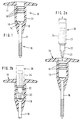
- FIG. 9 shows a fastener 40 according to an alternative variant that with the screwdriver 20 in the can be recorded and set according to the invention.
- the fastening element 40 is a such that is mainly used for fastening an insulation layer 31 on a wall 35, in particular a facade wall, is used, as shown in Fig. 10.
- the fastener 40 in turn has an upper plate 41 and a shaft 42 connected to it, whereby at a dowel part 43 is molded onto this shaft 42 downwards is.
- This dowel part 43 is similar to a conventional one Dowel longitudinal slots 44.
- the wall 35 a drill hole 36 is attached, the dowel part 43rd receives. Then the fastener 40 by means of Screwdriver 20 added so that the cylindrical Part of the screwdriver 45 shown in FIG. 10, back into the sleeve bore of the fastener 40 under Clamping effect is inserted. Similar to the one above described first embodiment is in the Sleeve bore of the fastener 40 a screw 46, as shown in Fig. 10 above.
- the Fastener is now through the insulation layer 31 pushed until the plate 41 at the front limit of the Insulation layer 31 is applied and then with the screwdriver 47 screwed the screw 46 into the dowel part 43 so that then the position according to the middle representation in FIG. 10 is reached. After screwing the Screw 46 and thus fastening the insulation layer 31 through the plate 41 of the fastener 40 can cylindrical part 45 of the screwdriver with the screwdriver tip 47 are pulled out as shown in the illustration below 10 and the next fastener 40 can be included.
Landscapes
- Engineering & Computer Science (AREA)
- Architecture (AREA)
- Civil Engineering (AREA)
- Structural Engineering (AREA)
- Mechanical Engineering (AREA)
- Physics & Mathematics (AREA)
- Acoustics & Sound (AREA)
- Electromagnetism (AREA)
- Details Of Spanners, Wrenches, And Screw Drivers And Accessories (AREA)
- Lining Or Joining Of Plastics Or The Like (AREA)
- Connection Of Plates (AREA)
Description
- Fig. 1
- einen Längsschnitt durch ein erfindungsgemäßes Befestigungselement;
- Fig. 2a
- eine schematische Ansicht eines erfindungsgemäßen Befestigungselements vor dem Einführen des Schraubers;
- Fig. 2b
- eine entsprechende schematische Ansicht des Befestigungselements von Fig. 2a nach dem Einführen des Schraubers;
- Fig. 3
- eine Ansicht eines kastenförmigen Magazins für Befestigungselemente nach der Erfindung;
- Fig. 4
- mehrere erfindungsgemäße Befestigungselemente, die sich in dem Magazin befinden und miteinander verkettet sind;
- Fig. 5
- eine schematisch vereinfachte Ansicht eines erfindungsgemäßen Einschraubwerkzeugs;
- Fig. 6
- eine perspektivische Ansicht eines Befestigungselements mit dem vorderen Teil des Einschraubwerkzeugs;
- Fig. 7
- eine Ansicht, die das Lösen eines Befestigungselements aus dem Magazin mittels des Einschraubwerkzeugs demonstriert;
- Fig. 8
- eine Ansicht betreffend die Verwendung eines erfindungsgemäßen Befestigungselements zur Befestigung einer Dämmschicht auf einem Flachdach im teilweisen Schnitt;
- Fig. 9
- eine perspektivische Ansicht eines Befestigungselements gemäß einer weiteren Variante;
- Fig. 10
- zeigt schematisch das Einschrauben eines Befestigungselements gemäß Fig. 9 zur Befestigung einer Dämmschicht an einer Wand in drei verschiedenen Stadien.
Claims (1)
- Verfahren zum Setzen von Befestigungselementen für die Befestigung einer Dämmschicht (31) an einer Unterkonstruktion (32), wobei die Befestigungselemente zweiteilig sind und ein Halteteil (10) mit Teller (11) und eine von diesem aufgenommene Schraube (16) umfassen, die in der Unterkonstruktion (32) verankert wird, wobei jeweils ein einzelnes Befestigungselement aus einen Vorrat mittels eines Schraubers (20) aufgenommen wird, wobei ein zylindrischer Teil (24) des Schraubers in eine Hülsenbohrung (13) des Halteteils (10) so eingeführt wird, dass das Halteteil (10) unter Klemmwirkung an dem Schrauber (20) verbleibt, danach ein Schaft (12) des Halteteils (10) in die Dämmschicht (31) eingeführt und die Schraube (16) in die Unterkonstruktion (32) mittels einer drehbaren Schrauberspitze (23) des Schraubers (20) eingeschraubt und schließlich der zylindrische Teil (24) des Schraubers (20) aus der Hülsenbohrung (13) des Halteteils (10) herausgezogen wird, und wobei die Befestigungselemente mit Halteteil (10) und Schraube (16) vormontiert sind, dadurch gekennzeichnet, dass die Befestigungselemente untereinander zu einer Kette verknüpft sind und beim Aufnehmen des Befestigungselements durch eine Schwenkbewegung des zylindrischen Teils (24) des Schraubers (20) nach dessen Einführung in die Hülsenbohrung (13) jeweils ein Befestigungselement aus der Kette gelöst wird, und dass der Schrauber (20) zwischen einem mit Handgriff (27) ausgerüsteten Gehäuse (26) und der Schrauberspitze (23) ein Verlängerungsteil (25) aufweist, das ausreichend lang ist, dass der Schrauber (20) beim Setzen von Befestigungselementen auf einem Flachdach von einer Bedienungsperson im Stehen verwendet werden kann.
Applications Claiming Priority (2)
| Application Number | Priority Date | Filing Date | Title |
|---|---|---|---|
| DE19600132A DE19600132A1 (de) | 1996-01-04 | 1996-01-04 | Verfahren zum Setzen von Befestigungselementen sowie Befestigungselemente für die Verwendung in diesem Verfahren |
| DE19600132 | 1996-01-04 |
Publications (2)
| Publication Number | Publication Date |
|---|---|
| EP0783063A1 EP0783063A1 (de) | 1997-07-09 |
| EP0783063B1 true EP0783063B1 (de) | 2002-01-09 |
Family
ID=7782132
Family Applications (1)
| Application Number | Title | Priority Date | Filing Date |
|---|---|---|---|
| EP96118568A Expired - Lifetime EP0783063B1 (de) | 1996-01-04 | 1996-11-20 | Verfahren zum Setzen von Befestigungselementen sowie Befestigungselemente für die Verwendung in diesem Verfahren |
Country Status (4)
| Country | Link |
|---|---|
| EP (1) | EP0783063B1 (de) |
| AT (1) | ATE211792T1 (de) |
| DE (2) | DE19600132A1 (de) |
| SI (1) | SI9600375A (de) |
Families Citing this family (10)
| Publication number | Priority date | Publication date | Assignee | Title |
|---|---|---|---|---|
| DE19754356A1 (de) | 1997-12-08 | 1999-06-10 | Fischer Artur Werke Gmbh | Werkzeug zur Montage von Dämmstoffhaltern zur Dachbahnbefestigung |
| DE29908107U1 (de) | 1999-05-06 | 2000-09-14 | Sfs Industrie Holding Ag, Heerbrugg | Befestigungselement zum Befestigen von Isolationsbahnen oder -platten auf einem Unterbau |
| NL1012608C2 (nl) * | 1999-07-15 | 2001-01-16 | Unidek Beheer Bv | Dakconstructie voorzien van op een metalen frame steunende en daarmee verbonden dakelementen. |
| DE10102703C1 (de) * | 2001-01-22 | 2002-07-25 | Sfs Ind Holding Ag Heerbrugg | Vorrichtung zum Einschrauben von Befestigungselementen |
| DE10102704C1 (de) * | 2001-01-22 | 2002-07-25 | Sfs Ind Holding Ag Heerbrugg | Vorrichtung zum Einschrauben von Befestigungselementen |
| DE202005017976U1 (de) * | 2005-11-15 | 2007-03-29 | Dr. Hahn Gmbh & Co. Kg | Montageschraube zur Befestigung von Beschlagteilen, insbesondere von Bandteilen an Hohlkammerprofilen |
| DE102011085641A1 (de) * | 2011-11-02 | 2013-05-02 | Van Roij Fasteners Europe B.V. | Setzwerkzeug mit Halte- und Freigabemechanismus zum Setzen einer Befestigungskombination in einen Untergrund |
| RU171444U1 (ru) * | 2016-02-09 | 2017-05-31 | Игорь Викторович Прохоров | Устройство для крепления |
| SE542031C2 (en) * | 2017-06-30 | 2020-02-11 | Bm Svets Ab | Pickup mechanism for feeding of weld pins, system for welding, and method for feeding of weld pins |
| CN107520793A (zh) * | 2017-09-23 | 2017-12-29 | 无锡先驱自动化科技有限公司 | 一种四瓣式打螺丝嘴 |
Family Cites Families (20)
| Publication number | Priority date | Publication date | Assignee | Title |
|---|---|---|---|---|
| GB552601A (en) * | 1941-12-06 | 1943-04-15 | Independent Pneumatic Tool Co | Improvements in or relating to fixtures or supports for screws and like headed fastening devices |
| US3249280A (en) * | 1964-12-24 | 1966-05-03 | Lowry Dev Corp | Nail feed mechanism |
| FI51728C (fi) * | 1976-03-16 | 1977-03-10 | Jarmo Jaervinen | Kiinnike. |
| DE3415201A1 (de) * | 1984-04-21 | 1985-10-31 | Arnold Knipping Gmbh, 5270 Gummersbach | Hilfseinrichtung bei der schraubverbindung von trapezblechen |
| US4862664A (en) * | 1987-12-23 | 1989-09-05 | Romine Robert L | Roofing fastener for fastener assembly and roof assemblies |
| DE8815185U1 (de) * | 1988-12-07 | 1989-02-09 | Ejot Adolf Böhl GmbH & Co KG, 5920 Bad Berleburg | Kunststoffdübel |
| DE3922350A1 (de) * | 1989-07-07 | 1991-01-17 | Itw Ateco Gmbh | Magazin fuer schrauben |
| DE9206380U1 (de) * | 1992-05-12 | 1993-09-09 | Fischerwerke Artur Fischer Gmbh & Co Kg, 72178 Waldachtal | Befestigungselement für Dämmstoffplatten |
| DE4224800A1 (de) * | 1992-07-27 | 1994-02-03 | Ivt H Blank | Elektronisch gesteuerte Setzvorrichtung |
| DE4240606A1 (de) * | 1992-12-03 | 1994-06-09 | Hardo Befestigungen Gmbh | Vorrichtung zum Einschrauben von Befestigungselementen |
| DE4240605A1 (de) * | 1992-12-03 | 1994-06-09 | Hardo Befestigungen Gmbh | Befestigungselement |
| DE4240607A1 (de) | 1992-12-03 | 1994-06-09 | Hardo Befestigungen Gmbh | Vorrichtung zum Einschrauben von Befestigungselementen |
| DE4318965C2 (de) * | 1993-06-08 | 1996-04-11 | Hilti Ag | Verfahren zum Setzen von Befestigungselementen |
| DE9311122U1 (de) * | 1993-07-26 | 1993-10-07 | EJOT Kunststofftechnik GmbH & Co KG, 57319 Bad Berleburg | Befestigungselement und Setzgerät für ein solches Befestigungselement |
| DE4329806A1 (de) * | 1993-09-03 | 1995-03-09 | Fischer Artur Werke Gmbh | Halteelement für die Befestigung von Dämmstoffplatten |
| CH687746A5 (de) * | 1993-11-25 | 1997-02-14 | Mungo Befestigungstech Ag | Werkzeug zum Einbringen eines mit Aussengewinde versehenen Befestigungselementes in Baumaterial. |
| DE9403652U1 (de) * | 1994-03-04 | 1994-06-09 | Fa. Robert Schröder, 42369 Wuppertal | Einsteckhalterung für Werkzeugeinsätze, insbesondere Schraubendreherbits |
| DE4416268C2 (de) * | 1994-05-07 | 1996-06-05 | Eugen F Karlein | Vorrichtung zum Ein- bzw. Ausdrehen von Innensechskant-Schrauben |
| DE9420474U1 (de) * | 1994-12-22 | 1995-03-23 | Harald Zahn GmbH, 69168 Wiesloch | Verkettete Befestigungselemente |
| DE29502229U1 (de) * | 1995-02-11 | 1995-03-30 | Magass, Walter, 69207 Sandhausen | Maschinell verarbeitbare und zu einem Gurt zusammengefaßte Befestigungselemente |
-
1996
- 1996-01-04 DE DE19600132A patent/DE19600132A1/de not_active Withdrawn
- 1996-11-20 DE DE59608556T patent/DE59608556D1/de not_active Expired - Fee Related
- 1996-11-20 EP EP96118568A patent/EP0783063B1/de not_active Expired - Lifetime
- 1996-11-20 AT AT96118568T patent/ATE211792T1/de not_active IP Right Cessation
- 1996-12-24 SI SI9600375A patent/SI9600375A/sl unknown
Also Published As
| Publication number | Publication date |
|---|---|
| DE19600132A1 (de) | 1997-07-10 |
| EP0783063A1 (de) | 1997-07-09 |
| DE59608556D1 (de) | 2002-02-14 |
| SI9600375A (en) | 1997-08-31 |
| ATE211792T1 (de) | 2002-01-15 |
Similar Documents
| Publication | Publication Date | Title |
|---|---|---|
| DE2359489C3 (de) | Grundplatte einer Skibindung, die auf einem Ski mit Hilfe von Holzschrauben befestigt wird | |
| DE69434858T2 (de) | Spannfutter | |
| DE69614593T2 (de) | Verankerungseinheit mit einem durch das auf den Bolzen einwirkende Drehmoment ausweitbaren Verankerungsteil | |
| DE10126747C2 (de) | Blindnietmutter und Befestigungseinheit | |
| DE10233866A1 (de) | Schraubwerkzeug mit austauschbarem Schaft | |
| DE3448086C2 (de) | ||
| DE3128844A1 (de) | Blindniet und damit hergestellte nietverbindung | |
| DE3009592A1 (de) | Kombinationswerkzeug | |
| DE3612514A1 (de) | Fraeser | |
| DE3305272C2 (de) | ||
| DE1475035B2 (de) | Befestigungsvorrichtung | |
| DE2744036C3 (de) | Vorrichtung zum Befestigen einer Dacheindeckungsplatte | |
| EP0783063A1 (de) | Verfahren zum Setzen von Befestigungselementen sowie Befestigungselemente für die Verwendung in diesem Verfahren | |
| DE3716808A1 (de) | Schraube | |
| DE202015102742U1 (de) | Höhenverstellbares Plattenlager | |
| WO1988009708A1 (fr) | Outil de vissage et vis utilisables avec cet outil | |
| DE4439973C2 (de) | Werkzeug zum Einbringen einer Schraubhülse in Baumaterial und zum Eindrehen einer Schraube in einen Aufnahmekanal der Schraubhülse | |
| DE19605709C1 (de) | Markierungselement für Bäume | |
| DE1925487A1 (de) | Schraubenzieher-Vorrichtung | |
| DE102016125025B4 (de) | Verwendung einer Befestigungseinrichtung zur Befestigung von Kappleisten, insbesondere an einer Wärmedämmung | |
| DE2946777C2 (de) | Schraubensteckschlüssel | |
| DE9417207U1 (de) | Aufsatzgerät für Handbohrmaschinen | |
| AT395114B (de) | Fuer skibindungen bestimmter backen | |
| DE10155333A1 (de) | Spannvorrichtung für ein Werkzeug | |
| DE2906840B2 (de) | Aufbohrwerkzeug |
Legal Events
| Date | Code | Title | Description |
|---|---|---|---|
| PUAI | Public reference made under article 153(3) epc to a published international application that has entered the european phase |
Free format text: ORIGINAL CODE: 0009012 |
|
| AK | Designated contracting states |
Kind code of ref document: A1 Designated state(s): AT BE CH DE FR GB IE IT LI NL |
|
| 17P | Request for examination filed |
Effective date: 19970604 |
|
| RAP1 | Party data changed (applicant data changed or rights of an application transferred) |
Owner name: FISCHERWERKE ARTUR FISCHER GMBH & CO. KG |
|
| 17Q | First examination report despatched |
Effective date: 19991217 |
|
| GRAG | Despatch of communication of intention to grant |
Free format text: ORIGINAL CODE: EPIDOS AGRA |
|
| GRAG | Despatch of communication of intention to grant |
Free format text: ORIGINAL CODE: EPIDOS AGRA |
|
| GRAH | Despatch of communication of intention to grant a patent |
Free format text: ORIGINAL CODE: EPIDOS IGRA |
|
| GRAH | Despatch of communication of intention to grant a patent |
Free format text: ORIGINAL CODE: EPIDOS IGRA |
|
| GRAA | (expected) grant |
Free format text: ORIGINAL CODE: 0009210 |
|
| REG | Reference to a national code |
Ref country code: GB Ref legal event code: IF02 |
|
| AK | Designated contracting states |
Kind code of ref document: B1 Designated state(s): AT BE CH DE FR GB IE IT LI NL |
|
| PG25 | Lapsed in a contracting state [announced via postgrant information from national office to epo] |
Ref country code: IE Free format text: LAPSE BECAUSE OF FAILURE TO SUBMIT A TRANSLATION OF THE DESCRIPTION OR TO PAY THE FEE WITHIN THE PRESCRIBED TIME-LIMIT Effective date: 20020109 |
|
| REF | Corresponds to: |
Ref document number: 211792 Country of ref document: AT Date of ref document: 20020115 Kind code of ref document: T |
|
| REG | Reference to a national code |
Ref country code: CH Ref legal event code: EP |
|
| REG | Reference to a national code |
Ref country code: IE Ref legal event code: FG4D Free format text: GERMAN |
|
| REF | Corresponds to: |
Ref document number: 59608556 Country of ref document: DE Date of ref document: 20020214 |
|
| GBT | Gb: translation of ep patent filed (gb section 77(6)(a)/1977) |
Effective date: 20020410 |
|
| ET | Fr: translation filed | ||
| REG | Reference to a national code |
Ref country code: IE Ref legal event code: FD4D |
|
| PGFP | Annual fee paid to national office [announced via postgrant information from national office to epo] |
Ref country code: FR Payment date: 20020910 Year of fee payment: 7 |
|
| PGFP | Annual fee paid to national office [announced via postgrant information from national office to epo] |
Ref country code: AT Payment date: 20021112 Year of fee payment: 7 |
|
| PLBE | No opposition filed within time limit |
Free format text: ORIGINAL CODE: 0009261 |
|
| STAA | Information on the status of an ep patent application or granted ep patent |
Free format text: STATUS: NO OPPOSITION FILED WITHIN TIME LIMIT |
|
| PGFP | Annual fee paid to national office [announced via postgrant information from national office to epo] |
Ref country code: GB Payment date: 20021120 Year of fee payment: 7 |
|
| PGFP | Annual fee paid to national office [announced via postgrant information from national office to epo] |
Ref country code: NL Payment date: 20021128 Year of fee payment: 7 |
|
| PG25 | Lapsed in a contracting state [announced via postgrant information from national office to epo] |
Ref country code: LI Free format text: LAPSE BECAUSE OF NON-PAYMENT OF DUE FEES Effective date: 20021130 Ref country code: CH Free format text: LAPSE BECAUSE OF NON-PAYMENT OF DUE FEES Effective date: 20021130 Ref country code: BE Free format text: LAPSE BECAUSE OF NON-PAYMENT OF DUE FEES Effective date: 20021130 |
|
| 26N | No opposition filed | ||
| BERE | Be: lapsed |
Owner name: FISCHERWERKE ARTUR *FISCHER G.M.B.H. & CO. K.G. Effective date: 20021130 |
|
| REG | Reference to a national code |
Ref country code: CH Ref legal event code: PL |
|
| PG25 | Lapsed in a contracting state [announced via postgrant information from national office to epo] |
Ref country code: GB Free format text: LAPSE BECAUSE OF NON-PAYMENT OF DUE FEES Effective date: 20031120 Ref country code: AT Free format text: LAPSE BECAUSE OF NON-PAYMENT OF DUE FEES Effective date: 20031120 |
|
| PG25 | Lapsed in a contracting state [announced via postgrant information from national office to epo] |
Ref country code: NL Free format text: LAPSE BECAUSE OF NON-PAYMENT OF DUE FEES Effective date: 20040601 |
|
| GBPC | Gb: european patent ceased through non-payment of renewal fee |
Effective date: 20031120 |
|
| PG25 | Lapsed in a contracting state [announced via postgrant information from national office to epo] |
Ref country code: FR Free format text: LAPSE BECAUSE OF NON-PAYMENT OF DUE FEES Effective date: 20040730 |
|
| NLV4 | Nl: lapsed or anulled due to non-payment of the annual fee |
Effective date: 20040601 |
|
| PGFP | Annual fee paid to national office [announced via postgrant information from national office to epo] |
Ref country code: DE Payment date: 20040908 Year of fee payment: 9 |
|
| REG | Reference to a national code |
Ref country code: FR Ref legal event code: ST |
|
| PG25 | Lapsed in a contracting state [announced via postgrant information from national office to epo] |
Ref country code: IT Free format text: LAPSE BECAUSE OF NON-PAYMENT OF DUE FEES Effective date: 20051120 |
|
| PG25 | Lapsed in a contracting state [announced via postgrant information from national office to epo] |
Ref country code: DE Free format text: LAPSE BECAUSE OF NON-PAYMENT OF DUE FEES Effective date: 20060601 |