EP0782246B1 - Verfahren und vorrichtung zur vermeidung des durchgehens eines motors - Google Patents
Verfahren und vorrichtung zur vermeidung des durchgehens eines motors Download PDFInfo
- Publication number
- EP0782246B1 EP0782246B1 EP96910211A EP96910211A EP0782246B1 EP 0782246 B1 EP0782246 B1 EP 0782246B1 EP 96910211 A EP96910211 A EP 96910211A EP 96910211 A EP96910211 A EP 96910211A EP 0782246 B1 EP0782246 B1 EP 0782246B1
- Authority
- EP
- European Patent Office
- Prior art keywords
- speed
- motor
- feedback value
- value
- sign
- Prior art date
- Legal status (The legal status is an assumption and is not a legal conclusion. Google has not performed a legal analysis and makes no representation as to the accuracy of the status listed.)
- Expired - Lifetime
Links
Images


Classifications
-
- G—PHYSICS
- G05—CONTROLLING; REGULATING
- G05B—CONTROL OR REGULATING SYSTEMS IN GENERAL; FUNCTIONAL ELEMENTS OF SUCH SYSTEMS; MONITORING OR TESTING ARRANGEMENTS FOR SUCH SYSTEMS OR ELEMENTS
- G05B19/00—Program-control systems
- G05B19/02—Program-control systems electric
- G05B19/18—Numerical control [NC], i.e. automatically operating machines, in particular machine tools, e.g. in a manufacturing environment, so as to execute positioning, movement or co-ordinated operations by means of program data in numerical form
- G05B19/406—Numerical control [NC], i.e. automatically operating machines, in particular machine tools, e.g. in a manufacturing environment, so as to execute positioning, movement or co-ordinated operations by means of program data in numerical form characterised by monitoring or safety
- G05B19/4062—Monitoring servoloop, e.g. overload of servomotor, loss of feedback or reference
-
- G—PHYSICS
- G05—CONTROLLING; REGULATING
- G05B—CONTROL OR REGULATING SYSTEMS IN GENERAL; FUNCTIONAL ELEMENTS OF SUCH SYSTEMS; MONITORING OR TESTING ARRANGEMENTS FOR SUCH SYSTEMS OR ELEMENTS
- G05B2219/00—Program-control systems
- G05B2219/30—Nc systems
- G05B2219/42—Servomotor, servo controller kind till VSS
- G05B2219/42062—Position and speed and current
-
- G—PHYSICS
- G05—CONTROLLING; REGULATING
- G05B—CONTROL OR REGULATING SYSTEMS IN GENERAL; FUNCTIONAL ELEMENTS OF SUCH SYSTEMS; MONITORING OR TESTING ARRANGEMENTS FOR SUCH SYSTEMS OR ELEMENTS
- G05B2219/00—Program-control systems
- G05B2219/30—Nc systems
- G05B2219/42—Servomotor, servo controller kind till VSS
- G05B2219/42309—Excess in speed
-
- G—PHYSICS
- G05—CONTROLLING; REGULATING
- G05B—CONTROL OR REGULATING SYSTEMS IN GENERAL; FUNCTIONAL ELEMENTS OF SUCH SYSTEMS; MONITORING OR TESTING ARRANGEMENTS FOR SUCH SYSTEMS OR ELEMENTS
- G05B2219/00—Program-control systems
- G05B2219/30—Nc systems
- G05B2219/42—Servomotor, servo controller kind till VSS
- G05B2219/42313—Excess in error for speed and different sign of position and speed feedback
Definitions
- the present invention relates to control of a servomotor, and more particularly to a method of and an apparatus for detecting an anomalous running of a motor controlled by a software servo control system.
- a method and apparatus are known from document JP 61 080 403 A.
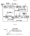
- FIG. 8 is a block diagram of a conventional servomotor control system.
- a control of the servomotor is generally performed in the following manner.
- the position of a mechanical system 6 detected by a position detector 8, such as an encoder, is fed back and the position feedback value is subtracted from a position command to obtain a position deviation by an error register 1.
- This position deviation is multiplied by a position gain Kp of an element 2 to obtain a speed command by a position loop process.
- a speed of a motor 5 detected by a speed detector 7 is fed back and the speed feedback value is subtracted from the speed command to obtain a speed deviation, so that a torque command (an electric current command) is obtained by a speed loop process such as a proportion-integration control.
- an electric current feedback value is subtracted from the torque command to obtain a voltage command by a current loop process, and the electric current is fed to a motor 5 by a servo amplifier 4 based on the voltage command.
- an element 3 performs a speed loop process and a current loop process.
- the position to be fed back is a position of a mechanical system 6 driven by the motor 5.
- FIGS. 9a-9c and 10a-10c respectively show relation between the position deviation and the speed command in the control system as shown in FIG. 8.
- FIGS. 9a-9c show a case in which the motor 5, the speed detector 7 and the position detector 8 operates in normal condition.
- the position of the mechanical system which is detected by the position detector 8, is fed back to a position command to obtain a position deviation, as shown in FIG. 9b.
- the speed command (FIG. 9c) is determined based on this position deviation and the motor is driven on the basis of the speed command to thereby reduce the position deviation.
- FIGS. 10a-10c show a case in which the motor 5, the speed detector 7 and the position detector 8 do not operate normally, to cause an anomalous running of the motor 5.
- the negative or positive sign of the feedback value which indicates the moving direction of the position of the mechanical system, is opposite to the sign indicating the direction of the position command.
- FIG. 10b although the actual position of the mechanical system approximates to the position command so that the actual position deviation decreases, a position deviation obtained by the error register 1 increases.
- the speed command increases in accordance with the increased position deviation, as shown in FIG. 10c, so that the motor is driven in accordance with the speed command. Thereby the motor is accelerated to cause an anomalous running.
- a cause for such anomalous running is exemplified by a misconnection of cables in attaching the speed detector and the position detector, by which the sign of detection signals outputted from the speed detector or the position detector is opposite to the direction of the position command.
- an anomalous running detector 10 which detects an anomalous running when the position deviation between the position command and the position feedback value exceeds a set value. Upon detection of an anomalous running, the anomalous running detector 10 issues an alarm or shuts off the energization of the motor.
- FIGS. 11a and 11b show the conventional anomalous running detecting method in which the position deviation is compared with a predetermined reference value a and the speed command is made zero when the position deviation exceeds the reference value ⁇ .
- the control system generally utilizes a pulse control.
- the pulse signals are depicted as continuous signals for the sake of explanation.
- a position loop of the control system for controlling a servomotor usually constitutes a first order delay system. Therefore, even when the servomotor operates normally, a position deviation determined by a feed speed and a position gain would practically exist.
- FIG. 12 is a diagram showing a position deviation produced in a first order delay system.
- a trapezoidal speed command indicated in a solid line is inputted, a time delay would occur in a resulting speed due to the first order delay of the position loop of the control system, thus producing a position deviation (indicated by hatching in FIG. 12), which corresponds to the integrated value.
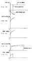
- FIGS. 13a-13h are diagrams for explaining the effect of a position deviation in detecting an anomalous running of the motor.
- FIGS. 13a-13d show the case in which the motor runs normally, while FIGS. 13e-13h show the case in which the motor runs an omalou sly .
- FIG. 13e shows the case where the direction of the position feedback is reversed with respect to the direction of the position command, to cause an anomalous running.
- the anomalous running detection is carried out using the reference value (chain line) of 1.5 ⁇ 0 which is determined by multiplying the position deviation ⁇ 0 by the coefficient of 1.5 as shown in FIG. 13f.
- the speed command is controlled to be zero (FIG. 13g). Since an anomalous running cannot be detected until the position deviation exceeds the reference value of 1.5 ⁇ 0 , the detection timing of the anomalous running is delayed.
- a method of detecting an anomalous running of a motor of the present invention is applied to a motor control system in which a position loop process is executed by feeding back a position of a mechanical system driven by the motor and a speed loop process is executed by feeding back the speed of the motor.
- This method of detecting an anomalous running of a motor comprises the steps of: comparing the speed feedback value of the motor with a reference value and discriminating whether or not the speed feedback value is larger than the reference value; comparing a sign of said speed feedback value with a sign of the position feedback value and discriminating whether or not the sign of the speed feedback value is identical with the sign of the position feedback value; and detecting the anomalous running of the motor based on the results of the two discriminations.
- the reference value to be compared with the speed feedback value may be set to a value which the motor speed reaches in compliance with a speed command produced in accordance with a position deviation which is determined based on a feed speed of the motor and a position gain in a position loop.
- the speed command value in the motor control system may be set to zero when the anomalous running of the motor is detected.
- the present invention provides an apparatus for detecting an anomalous running for carrying out the above method of detecting an anomalous running.
- This apparatus comprises: a first discriminator for comparing a speed feedback value of the motor with a reference value and discriminating whether or not the speed feedback value is larger than the reference value; a second discriminator for comparing a sign of the speed feedback value with a sign of the position feedback value and discriminating whether or not the sign of the speed feedback value is identical with the sign of the position feedback value; and an anomalous running detector for outputting an anomalous running detection signal when the feedback value is larger than the reference value and the sign of the speed feedback value is opposite to the sign of the position feedback value.
- a speed command value in the motor control system may be set to zero to stop the motor in response to the anomalous running detection signal outputted from the anomalous running detector.
- a position of mechanical system 6 detected by a position detector 8 such as an encoder is fed back and the position feedback value is subtracted from a position command to obtain a position deviation by an error register 1. This position deviation is multiplied by a position gain Kp of an element 2 to obtain a speed command by a position loop control.
- a speed of a motor 5 detected by a speed detector 7 is fed back and the speed feedback value is subtracted from the speed command to obtain a speed deviation so that a torque command (an electric current command) is obtained by a speed loop processing such as a proportional/integral control.
- a torque command an electric current command
- a voltage command is determined by a current loop process to control the motor 5 based on the voltage command through a servo amplifier 4.
- the speed feedback value from the speed detector 7 and the position feedback value from the position detector 8 are inputted to an anomalous running detector 9 for detecting the anomalous running of the motor 5 based on these inputted values.
- the output from the detector indicating the anomalous running is used as a control signal for setting the speed command for the motor control system to zero, or an alarm signal.
- FIG. 2 is a schematic diagram showing a relationship between the speed of the mechanical system 6 and the speed of the motor.
- the speed of the motor rises and then the speed of the mechanical system 6 rises after the lapse of delay time of the mechanical system 6.
- the delay time is determined in dependence on the characteristic of the mechanical system 6 connected to the motor 5.
- the position detector 8 is attached to the mechanical system 6 rather than the motor 5, the detected and fed back position is a position of the mechanical system 6 rather than a position of the motor 5. Therefore, an error is caused between the position feedback value obtained from the position detector 8 and the position of the motor 5 due to the delay.
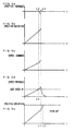
- FIGS. 3a-3d are diagrams showing response characteristics of the position and speed in the motor control system shown in FIG. 1.
- a motion command is distributed from a non-illustrated numerical control unit, and a position command in accordance with the motion command is inputted to the control system of FIG. 1.
- a position deviation is obtained from the difference between the position command the position feedback value, and a speed command is produced in accordance with the position deviation.
- a speed V 0 of the motor detected after lapse of the delay time t 0 of the mechanical system is the first available value for the detection performed by the anomalous running detector 9. Therefore, this speed V 0 is set to a base speed as a reference speed for detecting the anomalous running. This base speed is indicated in a chain line in FIG. 3d.
- the sign of the speed feedback value is identical with the sign of the position feedback value, it means that there is no inconsistency in the control direction of the motor, and the motor control is performed such that the position deviation and the speed deviation converge.
- the sign of the speed feedback value is opposite to the sign of the position feedback value, it means there is inconsistency in the control direction of the motor, and the motor control is performed such that the position deviation and the speed deviation diverge.
- a condition that the speed of the motor increases over the base speed and the control is performed so that the position deviation and the speed deviation are diverged is adopted as a reference for discriminating the anomalous running.
- FIGS. 4a-4e and 5a-5e are diagrams for explaining the state of the position and speed in detecting the anomalous running according to the present invention.
- the sign of the speed feedback value is negative and the sign of the position feedback value is positive.
- the speed feedback value is positive and the position feedback value is negative.
- FIGS. 4a, 4b, 4c and 4d respectively show variation of the position feedback, the position deviation, the speed command and the speed feedback and FIG. 4e show variation of the position deviation in the conventional method.
- the speed feedback value increases in negative towards the base speed V 0 of the negative value and reaches the base speed at the time t 0 .
- the anomalous running detector determines that an absolute value of the speed feedback value is not less than the base speed V 0 .
- the anomalous running detector subsequently determines that the speed feedback value is negative and the position feedback value is positive in sign, and hence they are reverse to each other in direction at time t 1 , to detect an anomalous running.
- FIG. 4e shows the detection of an anomalous running according to the conventional method in which a coefficient of 1.5 is multiplied by the position deviation quantity ⁇ 0 to obtain a reference for discrimination of the anomalous running.
- the anomalous running is detected at time t 2 later than the time t 1 .
- FIGS. 5a, 5b, 5c and 5d respectively show variation of the position feedback, the position deviation, the speed command and the speed feedback and FIG. 5e show variation of the position deviation in the convention method.
- the anomalous running detector determines that the absolute value of the speed feedback value is not less than the base speed V 0 .
- the anomalous running detector subsequently determines that the speed feedback value is positive and the position feedback value is negative in sign, and hence they are opposite to each other in direction at the time t 1 , to detect an anomalous running.
- FIG. 5e shows the detection of an anomalous running according to the conventional method in which a coefficient of 1.5 is multiplied by the position deviation quantity ⁇ 0 to obtain a reference for discrimination of the anomalous running.
- the anomalous running is detected at time t 2 later than the time t 1 .
- the anomalous running detection method of the present invention since a base speed is adopted, which is smaller than the speed level used in the conventional anomalous running detection, an anomalous running can be detected earlier than the conventional method.
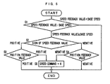
- Step S1 The speed feedback value from the speed detector 7 and the position feedback value are inputted to the anomalous running detector. First, the absolute value of the speed feedback value is compared with the base speed. If the absolute value of the speed feedback value is below the base speed, it is discriminated that the motor is not running anomalously, to terminate the processing. Contrary, if the speed feedback value is not less than the base speed, it is discriminated that there is a possibility of anomalous running of the motor, to proceed to the next Step S2.
- Step S2 The sign of the speed feedback value is determined. If the sign of the speed feedback value is positive, the processing proceeds to Step S3. Contrary, if the sign of the speed feedback value is negative, the processing proceeds to Step S4.
- Step S3 The sign of the position feedback value is determined. In this determination, if the sign of the position feedback value is negative, the sign of the speed feedback value and the sign of the position feedback value are opposite to each other. In this case, it is discriminated that the motor is running anomalously and the processing proceeds to Step S5 for restraining the anomalous running.
- Step S4 The sign of the position feedback value is determined. In this determination, if the sign of the position feedback value is negative, the sign of the speed feedback value and the sign of the position feedback value are opposite to each other. In this case, it is discriminated that the motor is running anomalously and the processing proceeds to Step S5 for restraining the anomalous running.
- Step S5 If it is discriminated that the motor is running anomalously, the processing such as stopping the motor by setting the speed command to zero in the control system or displaying an alarm is performed.
- the anomalous running of the motor can be detected by executing the foregoing processing in every predetermined period.
- the motor is prevented from the anomalous running due to an inverse-direction feedback signal which is caused by connecting the speed detector and/or the position detector, especially the position detector disposed separately from the control unit, in a wrong direction.
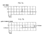
- FIGS. 7a and 7b The results of simulation of the anomalous running detecting method of the present invention are shown in FIGS. 7a and 7b.
- the base speed of 30 rpm is set.
- FIG. 7a shows the speed command and FIG. 7b shows the length of the anomalous running.
- the motor is stopped after running anomalously by 0.163 mm.
- FIGS. 14a and 14b show the result of simulation according to the conventional anomalous running detecting method under the same condition as that of the simulation shown in FIGS. 7a and 7b.
- FIG. 14a shows the speed command
- FIG. 14b shows the length of the anomalous running. In this simulation, the motor is stopped after running anomalously by 2.867 mm.
Landscapes
- Engineering & Computer Science (AREA)
- Human Computer Interaction (AREA)
- Manufacturing & Machinery (AREA)
- Physics & Mathematics (AREA)
- General Physics & Mathematics (AREA)
- Automation & Control Theory (AREA)
- Control Of Electric Motors In General (AREA)
- Control Of Position Or Direction (AREA)
Claims (6)
- Verfahren zum Erfassen eines anomalen Laufens eines Motors in einem Motor-Regelungssystem, in dem ein Positions-Schleifenregelungsprozess durch Rückkoppeln eines Positionssignals eines mechanischen Systems, das durch den Motor angetrieben wird, und ein Geschwindigkeits-Schleifenregelungsprozess durch Rückkoppeln eines Geschwindigkeitssignals des Motors ausgeführt werden, welches Verfahren Schritte umfasst zum(a) Vergleichen eines Geschwindigkeits-Rückkopplungssignalwerts des Motors mit einem Referenzwert und Unterscheiden, ob der Geschwindigkeits-Rückkopplungssignalwert größer als der Referenzwert ist oder nicht,(b) Vergleichen eines Vorzeichens des Geschwindigkeits-Rückkopplungssignalwerts mit einem Vorzeichen des Positions-Rückkopplungssignalwerts und Unterscheiden, ob das Vorzeichen des Geschwindigkeits-Rückkopplungssignalwerts mit dem Vorzeichen des Positions-Rückkopplungssignalwerts identisch ist oder nicht, und(c) Erfassen des anomalen Laufens des Motors auf der Grundlage des Ergebnisses der Unterscheidung in Schritt (a) und des Ergebnisses der Unterscheidung in Schritt (b).
- Verfahren zum Erfassen eines anomalen Laufens eines Motors nach Anspruch 1, wobei Schritt (c) einen Schritt zum Bestimmen enthält, dass der Motor anomal läuft, wenn in Schritt (a) ein Absolutwert des Geschwindigkeits-Rückkopplungssignalwerts größer als der Referenzwert ist und in Schritt (b) das Vorzeichen des Geschwindigkeits-Rückkopplungssignalwerts dem Vorzeichen des Positions-Rückkopplungssignalwerts entgegengesetzt ist.
- Verfahren zum Erfassen eines anomalen Laufens eines Motors nach Anspruch 1 oder 2, wobei der Referenzwert ein Wert ist, den die Motorgeschwindigkeit gemäß einem Geschwindigkeitsbefehl erreicht, der in Übereinstimmung mit einer Positionsabweichung erzeugt wird, die auf der Grundlage einer Vorschubgeschwindigkeit des Motors und eines Positionsübertragungsfaktors in der Positions-Regelungsschleife bestimmt ist.
- Verfahren zum Erfassen eines anomalen Laufens eines Motors nach Anspruch 1, 2 oder 3, das ferner einen Schritt umfasst zum Setzen eines Geschwindigkeitsbefehlswerts des Motor-Regelungssystems auf Null, wenn in Schritt (c) das anomale Laufen des Motors erfasst ist.
- Vorrichtung zum Erfassen eines anomalen Laufens eines Motors in einem Motor-Regelungssystem, in dem ein Positions-Schleifenregelungsprozess durch Rückkoppeln eines Positionssignals eines mechanischen Systems, das durch den Motor angetrieben wird, und ein Geschwindigkeits-Schleifenregelungsprozess durch Rückkoppeln eines Geschwindigkeitssignals des Motors ausgeführt werden, welche Vorrichtung umfasst:einen ersten Diskriminator zum Vergleichen eines Geschwindigkeits-Rückkopplungssignalwerts des Motors mit einem Referenzwert und Unterscheiden, ob der Geschwindigkeits-Rückkopplungssignalwert größer als der Referenzwert ist oder nicht,einen zweiten Diskriminator zum Vergleichen eines Vorzeichens des Geschwindigkeits-Rückkopplungssignalwerts mit einem Vorzeichen des Positions-Rückkopplungssignalwerts und Unterscheiden, ob das Vorzeichen des Geschwindigkeits-Rückkopplungssignalwerts mit dem Vorzeichen des Positions-Rückkopplungssignalwerts identisch ist oder nicht, undeinen Anomallauf-Detektor zum Ausgeben eines Anomallauf-Erfassungssignals, wenn der Rückkopplungssignalwert größer als der Referenzwert ist und das Vorzeichen des Geschwindigkeits-Rückkopplungssignalwerts dem Vorzeichen des Positions-Rückkopplungssignalwerts entgegengesetzt ist.
- Vorrichtung zum Erfassen eines anomalen Laufens eines Motors nach Anspruch 5, die ferner ein Mittel umfasst zum Setzen eines Geschwindigkeitsbefehlswerts des Motor-Regelungssystems auf Null, wenn das Anomallauf-Erfassungssignal von dem Anomallauf-Detektor ausgegeben ist.
Applications Claiming Priority (4)
| Application Number | Priority Date | Filing Date | Title |
|---|---|---|---|
| JP11655495 | 1995-04-19 | ||
| JP07116554A JP3091388B2 (ja) | 1995-04-19 | 1995-04-19 | モータの暴走検出方法および暴走検出装置 |
| JP116554/95 | 1995-04-19 | ||
| PCT/JP1996/001076 WO1996033549A1 (en) | 1995-04-19 | 1996-04-19 | Method and apparatus for detecting runaway of motor |
Publications (3)
| Publication Number | Publication Date |
|---|---|
| EP0782246A1 EP0782246A1 (de) | 1997-07-02 |
| EP0782246A4 EP0782246A4 (de) | 1998-12-16 |
| EP0782246B1 true EP0782246B1 (de) | 2003-10-08 |
Family
ID=14689997
Family Applications (1)
| Application Number | Title | Priority Date | Filing Date |
|---|---|---|---|
| EP96910211A Expired - Lifetime EP0782246B1 (de) | 1995-04-19 | 1996-04-19 | Verfahren und vorrichtung zur vermeidung des durchgehens eines motors |
Country Status (5)
| Country | Link |
|---|---|
| US (1) | US5767646A (de) |
| EP (1) | EP0782246B1 (de) |
| JP (1) | JP3091388B2 (de) |
| KR (1) | KR960039582A (de) |
| WO (1) | WO1996033549A1 (de) |
Families Citing this family (15)
| Publication number | Priority date | Publication date | Assignee | Title |
|---|---|---|---|---|
| RU2158467C2 (ru) * | 1998-05-20 | 2000-10-27 | Кубанский государственный технологический университет | Устройство управления электродвигателем постоянного тока |
| RU2158468C2 (ru) * | 1998-05-20 | 2000-10-27 | Кубанский государственный технологический университет | Электропривод постоянного тока |
| IL127370A (en) * | 1998-12-02 | 2004-05-12 | Yaskawa Eshed Technology Ltd | Control system and method for servo mechanism |
| JP2002199692A (ja) * | 2000-12-27 | 2002-07-12 | Minebea Co Ltd | ステッピングモータ及び、ステッピングモータ装置とその駆動方法 |
| JP4784025B2 (ja) * | 2001-09-19 | 2011-09-28 | パナソニック株式会社 | 位置決め制御方法および位置決め制御装置 |
| RU2249242C1 (ru) * | 2003-08-04 | 2005-03-27 | Кубанский государственный технологический университет | Система автоматического регулирования частоты вращения исполнительного органа механизма, упруго связанного с электродвигателем, одноконтурная астатическая второго порядка |
| JP4622448B2 (ja) * | 2004-10-19 | 2011-02-02 | 株式会社ジェイテクト | 車両用操舵装置 |
| JP4085112B2 (ja) | 2006-01-31 | 2008-05-14 | ファナック株式会社 | モータ制御方法およびモータ制御装置 |
| WO2008071538A1 (de) * | 2006-12-14 | 2008-06-19 | Continental Automotive Gmbh | Verfahren und vorrichtung zum verfolgen der position einer von einem elektromotor angetriebenen komponente |
| JP5273582B2 (ja) * | 2008-02-20 | 2013-08-28 | 日本精工株式会社 | サーボモータの制御方法 |
| RU2370878C1 (ru) * | 2008-03-24 | 2009-10-20 | Государственное образовательное учреждение высшего профессионального образования "Кубанский государственный технологический университет" (ГОУВПО "КубГТУ") | Программно-управляемый электропривод с идеальным валопроводом |
| JP5341534B2 (ja) * | 2009-01-23 | 2013-11-13 | セミコンダクター・コンポーネンツ・インダストリーズ・リミテッド・ライアビリティ・カンパニー | モータ速度制御装置 |
| RU2412525C1 (ru) * | 2010-01-11 | 2011-02-20 | Государственное образовательное учреждение высшего профессионального образования "Кубанский государственный технологический университет" (ГОУ ВПО "КубГТУ") | Программно-управляемый электропривод с идеальным валопроводом |
| CN104533881B (zh) * | 2014-12-04 | 2016-09-21 | 上海中联重科桩工机械有限公司 | 工程机械行走跑偏原因的判断系统及判断方法 |
| JP6100816B2 (ja) * | 2015-02-19 | 2017-03-22 | ファナック株式会社 | 位置偏差過大を抑制する速度制御を行う数値制御装置 |
Family Cites Families (22)
| Publication number | Priority date | Publication date | Assignee | Title |
|---|---|---|---|---|
| US3555252A (en) * | 1967-05-11 | 1971-01-12 | Leeds & Northrup Co | Learning control of actuators in control systems |
| JPS5091711A (de) * | 1973-12-18 | 1975-07-22 | ||
| JPS5846960B2 (ja) * | 1979-03-27 | 1983-10-19 | ファナック株式会社 | 電動機負荷の異常状態検出および保護装置 |
| JPS563587A (en) * | 1979-06-22 | 1981-01-14 | Yaskawa Electric Mfg Co Ltd | Electric motor speed monitoring device |
| US4484287A (en) * | 1980-09-30 | 1984-11-20 | Fujitsu Fanuc Limited | System for restoring numerically controlled machine tool to former condition |
| US4401930A (en) * | 1980-12-30 | 1983-08-30 | Toyota Jidosha Kogyo Kabushiki Kaisha | Method of sensing position of movable body and apparatus therefor |
| JPS59112308A (ja) * | 1982-12-20 | 1984-06-28 | Fanuc Ltd | 数値制御装置 |
| JPS59172993A (ja) * | 1983-03-23 | 1984-09-29 | Hitachi Ltd | 位置検出器付dcモ−トルの逆回転防止装置 |
| JPS6180403A (ja) * | 1984-09-28 | 1986-04-24 | Mitsubishi Electric Corp | デイジタル制御装置 |
| DE3590662T1 (de) * | 1984-12-22 | 1987-02-19 | ||
| JPS6232402A (ja) * | 1985-08-05 | 1987-02-12 | Nippon Sheet Glass Co Ltd | 合成樹脂球レンズの製造方法 |
| JPS6232402U (de) * | 1985-08-14 | 1987-02-26 | ||
| JPS6281492U (de) * | 1985-11-11 | 1987-05-25 | ||
| JPS6443084A (en) * | 1987-08-10 | 1989-02-15 | Hitachi Ltd | Servo abnormality detection |
| US4965504A (en) * | 1988-09-20 | 1990-10-23 | Hitachi, Ltd. | Control apparatus for inverter for driving AC motor |
| JP2511539B2 (ja) * | 1989-10-31 | 1996-06-26 | 三田工業株式会社 | モ―タ回転制御装置の異常検出装置 |
| JPH0454885A (ja) * | 1990-06-19 | 1992-02-21 | Mitsubishi Electric Corp | サーボモータ用監視装置 |
| JPH04165503A (ja) * | 1990-10-30 | 1992-06-11 | Komatsu Ltd | 駆動装置の制御方法およびその装置 |
| JPH04279906A (ja) * | 1991-02-18 | 1992-10-06 | Mitsubishi Electric Corp | サーボ制御装置 |
| JP3058360B2 (ja) * | 1991-07-12 | 2000-07-04 | 株式会社安川電機 | サーボモータの暴走検出・防止方法 |
| JP3174967B2 (ja) * | 1992-03-23 | 2001-06-11 | 株式会社日立製作所 | 電動機制御装置 |
| JPH06292377A (ja) * | 1993-04-02 | 1994-10-18 | Meidensha Corp | サーボ制御系の制御部 |
-
1995
- 1995-04-19 JP JP07116554A patent/JP3091388B2/ja not_active Expired - Lifetime
-
1996
- 1996-04-18 KR KR1019960011749A patent/KR960039582A/ko not_active Withdrawn
- 1996-04-19 EP EP96910211A patent/EP0782246B1/de not_active Expired - Lifetime
- 1996-04-19 WO PCT/JP1996/001076 patent/WO1996033549A1/ja not_active Ceased
- 1996-04-19 US US08/750,615 patent/US5767646A/en not_active Expired - Fee Related
Also Published As
| Publication number | Publication date |
|---|---|
| EP0782246A1 (de) | 1997-07-02 |
| EP0782246A4 (de) | 1998-12-16 |
| KR960039582A (ko) | 1996-11-25 |
| US5767646A (en) | 1998-06-16 |
| WO1996033549A1 (en) | 1996-10-24 |
| JP3091388B2 (ja) | 2000-09-25 |
| JPH08294295A (ja) | 1996-11-05 |
Similar Documents
| Publication | Publication Date | Title |
|---|---|---|
| EP0782246B1 (de) | Verfahren und vorrichtung zur vermeidung des durchgehens eines motors | |
| US5418440A (en) | Position control device for servomotor | |
| US5210476A (en) | Servo motor monitoring unit | |
| US5304906A (en) | Collision detecting method using an observer | |
| US5259473A (en) | Electric power steering apparatus | |
| US5823164A (en) | Throttle control device | |
| KR970002525A (ko) | 서보제어시스템의 이상검출ㆍ진단방법 및 자동적정화방법 | |
| JPH08238938A (ja) | 自動車の閉鎖部材の駆動装置 | |
| US4878077A (en) | Motor drive and control apparatus for a camera | |
| EP0534690A2 (de) | Einrichtung zur Steuerung eines Servo-Motors | |
| EP0464211A1 (de) | Verfahren zur Bestimmung eines Zusammenstosses unter Verwendung eines Beobachters | |
| US5020617A (en) | Method and apparatus for checking torque sensor in electric power steering system for vehicle | |
| US5046467A (en) | System for setting the throttle flap angle for an internal combustion engine | |
| EP0604663A1 (de) | Verfahren zur schätzung von trägheit und stör-drehmoment und verfahren zum erkennen einer unüblichen belastung | |
| JP2767693B2 (ja) | 自動ドアの開閉制御方法及び装置 | |
| KR0166915B1 (ko) | 모터의 속도 및 위상 제어장치 | |
| KR920019493A (ko) | 로보트시스템의 위치제어장치 및 그 제어방법 | |
| JPH037672A (ja) | 負荷駆動回路 | |
| JP2737967B2 (ja) | 無人搬送車の暴走検出方法 | |
| JPH06261574A (ja) | サーボモータの制御装置 | |
| JP2513978Y2 (ja) | 速度制御装置の異常速度検出器 | |
| JP2000134966A (ja) | モータ異常検出装置 | |
| KR20230139162A (ko) | 차량 및 차량의 제어 방법. | |
| JP2791094B2 (ja) | サーボ系の異常検出装置 | |
| JPS6020724A (ja) | 電動機駆動装置 |
Legal Events
| Date | Code | Title | Description |
|---|---|---|---|
| PUAI | Public reference made under article 153(3) epc to a published international application that has entered the european phase |
Free format text: ORIGINAL CODE: 0009012 |
|
| 17P | Request for examination filed |
Effective date: 19970114 |
|
| AK | Designated contracting states |
Kind code of ref document: A1 Designated state(s): GB IT |
|
| A4 | Supplementary search report drawn up and despatched |
Effective date: 19981104 |
|
| AK | Designated contracting states |
Kind code of ref document: A4 Designated state(s): GB IT |
|
| GRAH | Despatch of communication of intention to grant a patent |
Free format text: ORIGINAL CODE: EPIDOS IGRA |
|
| GRAS | Grant fee paid |
Free format text: ORIGINAL CODE: EPIDOSNIGR3 |
|
| GRAA | (expected) grant |
Free format text: ORIGINAL CODE: 0009210 |
|
| RBV | Designated contracting states (corrected) |
Designated state(s): IT |
|
| AK | Designated contracting states |
Kind code of ref document: B1 Designated state(s): IT |
|
| RAP2 | Party data changed (patent owner data changed or rights of a patent transferred) |
Owner name: FANUC LTD |
|
| PLBE | No opposition filed within time limit |
Free format text: ORIGINAL CODE: 0009261 |
|
| STAA | Information on the status of an ep patent application or granted ep patent |
Free format text: STATUS: NO OPPOSITION FILED WITHIN TIME LIMIT |
|
| 26N | No opposition filed |
Effective date: 20040709 |
|
| PGFP | Annual fee paid to national office [announced via postgrant information from national office to epo] |
Ref country code: IT Payment date: 20080424 Year of fee payment: 13 |
|
| PG25 | Lapsed in a contracting state [announced via postgrant information from national office to epo] |
Ref country code: IT Free format text: LAPSE BECAUSE OF NON-PAYMENT OF DUE FEES Effective date: 20090419 |