EP0769730B1 - Verfahren zum Betrieb einer Bilderwärmungsvorrichtung - Google Patents
Verfahren zum Betrieb einer Bilderwärmungsvorrichtung Download PDFInfo
- Publication number
- EP0769730B1 EP0769730B1 EP96116757A EP96116757A EP0769730B1 EP 0769730 B1 EP0769730 B1 EP 0769730B1 EP 96116757 A EP96116757 A EP 96116757A EP 96116757 A EP96116757 A EP 96116757A EP 0769730 B1 EP0769730 B1 EP 0769730B1
- Authority
- EP
- European Patent Office
- Prior art keywords
- temperature
- heating
- change rate
- heating member
- image
- Prior art date
- Legal status (The legal status is an assumption and is not a legal conclusion. Google has not performed a legal analysis and makes no representation as to the accuracy of the status listed.)
- Expired - Lifetime
Links
- 238000010438 heat treatment Methods 0.000 title claims description 64
- 238000000034 method Methods 0.000 title claims description 18
- 230000008859 change Effects 0.000 claims description 26
- 238000009826 distribution Methods 0.000 description 20
- 230000002950 deficient Effects 0.000 description 5
- XEEYBQQBJWHFJM-UHFFFAOYSA-N Iron Chemical compound [Fe] XEEYBQQBJWHFJM-UHFFFAOYSA-N 0.000 description 4
- 238000005259 measurement Methods 0.000 description 4
- 238000004140 cleaning Methods 0.000 description 3
- 239000000463 material Substances 0.000 description 3
- 230000004913 activation Effects 0.000 description 2
- XAGFODPZIPBFFR-UHFFFAOYSA-N aluminium Chemical compound [Al] XAGFODPZIPBFFR-UHFFFAOYSA-N 0.000 description 2
- 229910052782 aluminium Inorganic materials 0.000 description 2
- 229910052742 iron Inorganic materials 0.000 description 2
- 229920001296 polysiloxane Polymers 0.000 description 2
- 239000004810 polytetrafluoroethylene Substances 0.000 description 2
- 229920001343 polytetrafluoroethylene Polymers 0.000 description 2
- 230000009467 reduction Effects 0.000 description 2
- 230000004044 response Effects 0.000 description 2
- 229910001220 stainless steel Inorganic materials 0.000 description 2
- 239000010935 stainless steel Substances 0.000 description 2
- AZDRQVAHHNSJOQ-UHFFFAOYSA-N alumane Chemical group [AlH3] AZDRQVAHHNSJOQ-UHFFFAOYSA-N 0.000 description 1
- 238000004891 communication Methods 0.000 description 1
- 230000007812 deficiency Effects 0.000 description 1
- 230000001419 dependent effect Effects 0.000 description 1
- 230000008021 deposition Effects 0.000 description 1
- 238000011161 development Methods 0.000 description 1
- 230000018109 developmental process Effects 0.000 description 1
- 238000007786 electrostatic charging Methods 0.000 description 1
- 239000011810 insulating material Substances 0.000 description 1
- 230000004048 modification Effects 0.000 description 1
- 238000012986 modification Methods 0.000 description 1
- 239000012260 resinous material Substances 0.000 description 1
- 230000000630 rising effect Effects 0.000 description 1
- 238000004904 shortening Methods 0.000 description 1
- 229920002379 silicone rubber Polymers 0.000 description 1
- 239000004945 silicone rubber Substances 0.000 description 1
Images




Classifications
-
- G—PHYSICS
- G03—PHOTOGRAPHY; CINEMATOGRAPHY; ANALOGOUS TECHNIQUES USING WAVES OTHER THAN OPTICAL WAVES; ELECTROGRAPHY; HOLOGRAPHY
- G03G—ELECTROGRAPHY; ELECTROPHOTOGRAPHY; MAGNETOGRAPHY
- G03G15/00—Apparatus for electrographic processes using a charge pattern
- G03G15/20—Apparatus for electrographic processes using a charge pattern for fixing, e.g. by using heat
- G03G15/2003—Apparatus for electrographic processes using a charge pattern for fixing, e.g. by using heat using heat
- G03G15/2014—Apparatus for electrographic processes using a charge pattern for fixing, e.g. by using heat using heat using contact heat
- G03G15/2039—Apparatus for electrographic processes using a charge pattern for fixing, e.g. by using heat using heat using contact heat with means for controlling the fixing temperature
Definitions
- the present invention relates to a method of operating an image heating device for heating an image borne by a recording sheet.
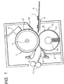
- a heating roller 1 is composed for example of a metallic core 11 such as of aluminum or iron, and a releasing resinous layer 12 such as of PFA or PTFE, and is heated internally by means of heater 4.
- the temperature of the heating roller 1 is detected as the surface temperature thereof by a temperature detecting element 3 maintained in contact with the heating roller 1, and the surface temperature is maintained at a predetermined temperature by intermittent activation of the heater 4 by means of a temperature control circuit (not shown).
- the temperature detecting element can be positioned within the passing area of the recording sheet in case of the image heating device equipped with cleaning means, but, in case of the image heating device lacking such cleaning means, it is generally provided in a non-image area in order to prevent smear on the image.
- a pressure roller 2, rotated in pressure contact with the heating roller 1, is composed of a metallic core 13 such as of aluminum or iron, a heat-resistant elastic layer 14 such as of silicone rubber or silicone sponge of a low hardness provided thereon, and a surfacial covering layer 15 composed of a releasing resinous material such as PFA or PTFE.
- the entrance guide 6 is generally composed of a controlled resistance material such as PBT (having a resistance of 10 8 to 10 10 ⁇ ), or has a metallic guide surface such as of stainless steel and employs the above-mentioned controlled resistance material at the junction with a fixing frame. This is avoid drawbacks such as toner scattering, caused by electrostatic charging of the guide surface resulting from the friction contact with the recording sheet if the entrance guide is composed of an insulating material.
- the heating roller 1 and the pressure roller 2 are customary with adequate inverse crowning in the longitudinal direction thereof and to adequately adjust the position of entry of the recording sheet into the nip between the heating roller and the pressure roller, by means of the entrance guide 6.
- the thickness of the heating roller 1 is often made equal to or less than 1.0 mm, in order to reduce the heat capacity of the heating roller, thereby shortening the warm-up time.
- the printing speed has to be significantly lowered in such printing with small-sized sheets.
- Fig. 2 shows the cross-sectional structure of such configuration
- Fig. 3 shows the heat distribution of the heaters and the arrangement of segments.
- the illustrated heat distribution of the heaters is designed for sheet transportation with the reference position at the center.
- a heater 4a is used for the printing of a small-sized sheet, and has heat distribution in a portion where the heat is absorbed by the sheet.
- the heater 4b is used, in combination with the heater 4a, for the printing of a large-sized sheet.
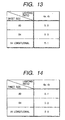
- Fig. 13 shows the heater lighting ratio for different sheet sizes.
- the heater 4b For the lighting of the heater 4a for 500 msec., the heater 4b is turned on for 500 msec in case of printing an A3-sized sheet, 300 msec in case of printing a B4-sized sheet and 100 msec in case of printing a longitudinally-oblong A4-sized sheet.
- Such lighting ratios are generally so selected as to obtain a substantially flat temperature distribution on the heating roller, for the sheets of a most frequently used weight range of 65 to 80 g/m 2 .
- the temperature distribution on the heating roller becomes different because of the difference in the heat amount carried away by the sheets, depending on the weight thereof.
- the temperature distribution (at the thirtieth sheet or thereafter) assumes the form shown in Fig. 4, and, even for the sheets of a same size, the image fixing ability may become deficient by the temperature decrease in the central area, particularly in case of thick recording sheets. This is because the longitudinal heat conduction in the metallic core of the thin heating roller cannot match the supplied heat amount. A similar phenomenon may be caused by a lowered voltage of the power supply.
- a lowering by 15% of the power supply voltage reduces the output of the heater to 78% of the rated power, so that the output of a heater of 800W is reduced to 623W.
- the image fixing ability may become deficient at the central area, even for a sheet weight of about 90 g/m 2 .
- Document EP-A-0 523 638 discloses an method for operating an image heating device as defined in the preambles of the independent claims 1 to 3.
- the power supply to a heater of the image heating device is controlled based on a rising speed of the temperature detected during a period from the time when the power supply to the heater is started till the time when the temperature reaches the predetermined temperature.
- the object of the present invention is to provide an method for operating an image heating device such that of satisfactory image fixation regardless of the kind of the recording sheet or the fluctuation in the power supply voltage is possible.
- Fig. 2 is a cross-sectional view of a fixing device, constituting an embodiment of the image heating device of the present invention
- Fig. 3 shows the heat distribution of heaters and the arrangement of segments thereof.
- the recording sheets up to A3 size (297 mm in width) are transported with a reference position at the center, so that the heat distribution of the heaters is made symmetrical with respect to the central reference position.
- Heaters (heat generating members) 4a, 4b have a rated power of 500 W upon receiving an input voltage of 100 V.
- a fixing roller (heating member) 1 has a diameter of 40 mm and a thickness of 1.0 mm, and is composed of an aluminum core 11 and a mold releasing PFA layer 12 at the surface.
- a pressure roller 2 constituting a backup member for forming a nip with the heating member, has a diameter of 30 mm and a hardness of 50°, is composed of a core 13 of stainless steel, an elastic layer 14 of silicone sponge and a surfacial releasing PFA layer 15, and is adapted to form a nip of a width of 5.0 mm in cooperation with the fixing roller under a pressure of 200 N.
- a temperature detecting element is provided in a non-image area (non-passing area of the sheets in the present embodiment) where the toner image does not come into contact with the fixing roller, so that the temperature detecting element is free from the toner deposition and the cleaning means can therefore be dispensed with.
- Such configuration allows printing operation of 30 sheets/minute, with A4-sized sheets transported in the transversally oblong position.
- the stand-by temperature is set equal to or lower than the minimum allowable fixing temperature, based on a fact that the image fixation in the initial period of the printing operation can be achieved at a temperature lower than in a continuous printing operation, utilizing the heat capacity of the fixing device.
- Such setting is selected in order to measure the temperature change rate, by preparing a certain period for reaching the fixing temperature from the stand-by temperature.
- An experimental measurement indicates that the temperature change rate can be exactly measured and judged if the measuring period is as long as about 5 seconds. Consequently, in the present embodiment, the temperature change rate is measured from the first to third sheets in the continuous printing operation. It is naturally possible also to complete the measurement in the first sheet.
- a pre-rotation step initiated in response to a print signal, and the image forming apparatus enters the printing operation from the stand-by state, through the pre-rotation step.
- a sheet enters the nip after the release of an image writing signal (VSYNC signal) from a video controller (not shown) but before the detected temperature reaches the controlled temperature.
- the printing operation for the 1st sheet is initiated, after the release of the VSYNC signal, with a predetermined lighting ratio of the heaters until the detected temperature reaches the controlled temperature, and the temperature increase rate is measured in the course of the continuous printing operation. More specifically, in the present embodiment, the two heaters are fully turned on (communication duty 100%) from the stand-by temperature to the controlled temperature, and the temperature increase rate is measured with the thermistor.
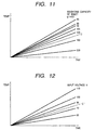
- Fig. 11 shows the temperature increase rate for different paper weights, for an input voltage of 100 V.
- the image heating condition in the continuous printing operation is switched according to whether the temperature increase rate is larger or smaller than a broken line C in Fig. 11.
- Such switching is made by a CPU constituting heating condition determination means. More specifically, if the temperature increase rate is smaller than the broken line C, the interval of sheets in the continuous printing operation is made larger than that in the normal operation, thereby preventing the decrease of temperature in the central portion of the fixing roller.
- the minimum temperature in case of continuous printing of the sheets of 200 g/m 2 could be brought into the allowable fixing temperature range, by reducing the throughput for the A4-sized sheets (transported in transversally oblong position) by 20%, from 30 sheets/minute in the normal state to 24 sheets/minute (starting from the fourth sheet in the continuous printing operation).
- the present embodiment employs two different intervals of sheets according to the temperature increase rate, but it is also possible to adopt three or more sheet intervals depending on the temperature increase rate.
- the productivity of the device can be improved by selecting the sheet interval in finer manner.
- the temperature distribution as shown in Fig. 4 results from the deficiency in heat supply in the central area. Therefore, if a thick sheet is identified from the measurement of the temperature increase rate, conducted for 5 seconds after the entry of the leading end of the sheet into the nip (namely if the slope of temperature increase being smaller than the line C in Fig. 11), the lighting ratio of the heaters is modified as shown in Fig. 14, in order to alter the image heating condition. After the measurement of the temperature increase rate, the ratio of lighting of the heater 4a is increased in the 4th and subsequent sheets in the continuous printing operation, thereby increasing the heat supply to the central part of the fixing roller and bringing the minimum temperature in such central part within the allowable fixing temperature range as shown in Fig. 5.
- the lighting ratio is varied in only one step, but it is also possible to detect the sheet weight from the actual temperature slope and to modify the lighting ratio in plural steps so as to optimize the temperature distribution of the fixing roller to the sheet weight.
- the fixing ability may not be ensured by the present embodiment only, for example in case of a lowered power supply voltage.
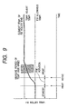
- the control temperature cannot be maintained (the detected temperature does not reach the control temperature or continues to decrease) even with the modification of the lighting ratio of the heaters, the fixing ability is secured by a reduction of the throughput as shown in Fig. 10.
- the throughput is reduced if the control temperature is not reached after the printing of a predetermined number of sheets after the release of the VSYNC signal, but it is also possible to utilize a timer and to reduce the throughput in case the control temperature is not reached after a predetermined time.
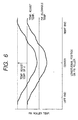
- a third embodiment of the present invention in which, in case the fixing roller assumes the temperature distribution as shown in Fig. 4 because of the high sheet weight and the temperature in the central part of the fixing roller does not reach the allowable fixing temperature, the deficient heat required in the central part as shown in Fig. 6 is secured by an increase in the controlled temperature for fixing.
- the lighting ratio of the heaters is weighted at the center, for example in case of the longitudinally oblong A4-sized sheets, the change in the lighting ratio can only scarcely increase the heat supply in the center, in response to an increase in the sheet weight.
- the change from the condition shown in Fig. 13 to that shown in Fig. 14 can only provide a change from 5:1 to 5:0.
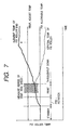
- the sheet weight is identified from the slope of the temperature increase in the first printed sheet and the controlled temperature is raised by d if the slope is smaller than an increase rate C.
- the increase rate C for switching the control is preferably selected for each sheet size, since the temperature increase rate varies depending on the sheet size.
- the control is carried out with respect to the temperature increase rate as a function of the sheet weight, but the present invention is applicable also to the fluctuation in the input voltage, as explained in the following.
- Figs. 12 and 8 respectively show the temperature increase rate in the initial stage of printing operation and the temperature distribution on the fixing roller, for different input voltages in a printing operation on the sheets of 128 g/m 2 .
- a control as explained in the foregoing is possible by switching the control according to a temperature slope C' corresponding to about 93 V. If the image forming apparatus itself is provided with a device for detecting the power supply voltage, it is possible to set the control parameters respectively for the input voltage and for the sheet weight.
- the stable fixing ability can be constantly secured even for simultaneous fluctuations in the input voltage and in the sheet weight, by adopting a temperature increase rate capable of securing the fixing ability, for the criterion of judgment.
- the control is switched solely depending on the sheet weight, and, if the input voltage is lower than the rated voltage, the control is switched depending on both the input voltage and the sheet weight, according to the larger one of C corresponding to the sheet size and C'.
Landscapes
- Physics & Mathematics (AREA)
- General Physics & Mathematics (AREA)
- Fixing For Electrophotography (AREA)
- Control Or Security For Electrophotography (AREA)
Claims (6)
- Verfahren zum Betrieb einer Bilderheizvorrichtung mit einem Heizteil (1) und einem Stützteil (2) zur Ausbildung eines Spalts zusammen mit dem Heizteil (1), wobei das Verfahren den Schritt
Erfassen einer Temperatur des Heizteils (1) aufweist,
dadurch gekennzeichnet, dass
während des Erfassungsschritts eine Temperaturänderungsrate erfasst wird, während ein Aufzeichnungsblatt in der Spalte gehalten wird, wobei die Temperaturänderungsrate durch das Heizteil verursacht wird,
und das Verfahren weiterhin den Schritt aufweist:Bestimmen einer Heizbedingung entsprechend der erfassten Temperaturänderungsrate und Schalten des Betriebs der Bildheizvorrichtung auf die bestimmte Heizbedingung, wobeidie Heizbedingung ein Durchlassintervall der Aufzeichnungsblätter in dem Spalt ist. - Verfahren zum Betrieb einer Bilderheizvorrichtung mit einem Heizteil (1) und einem Stützteil (2) zur Ausbildung eines Spalts zusammen mit dem Heizteil (1), wobei das Verfahren den Schritt
Erfassen einer Temperatur des Heizteils (1) aufweist,
dadurch gekennzeichnet, dass
während des Erfassungsschritts eine Temperaturänderungsrate erfasst wird, während ein Aufzeichnungsblatt in der Spalte gehalten wird, wobei die Temperaturänderungsrate durch das Heizteil verursacht wird,
und das Verfahren weiterhin den Schritt aufweist:Bestimmen einer Heizbedingung entsprechend der erfassten Temperaturänderungsrate und Schalten des Betriebs der Bildheizvorrichtung auf die bestimmte Heizbedingung, wobeidie Heizbedingung eine gesteuerte Temperatur des Heizteils ist. - Verfahren zum Betrieb einer Bilderheizvorrichtung mit einem Heizteil (1) und einem Stützteil (2) zur Ausbildung eines Spalts zusammen mit dem Heizteil (1), wobei das Verfahren die Schritt
Erfassen einer Temperatur des Heizteils (1) aufweist,
dadurch gekennzeichnet, dass
während des Erfassungsschritts eine Temperaturänderungsrate erfasst wird, während ein Aufzeichnungsblatt in der Spalte gehalten wird, wobei die Temperaturänderungsrate durch das Heizteil verursacht wird,
und das Verfahren weiterhin den Schritt aufweist:Bestimmen einer Heizbedingung entsprechend der erfassten Temperaturänderungsrate und Schalten des Betriebs der Bildheizvorrichtung auf die bestimmte Heizbedingung, wobeidas Heizteil (1) mehrere Wärmeerzeugungsteile (4a, 4b) zur Erzeugung der Wärme mittels Stromzufuhr aufweist, unddie Heizbedingung das Stromzufuhrverhältnis zu den mehreren Wärmeerzeugungsteilen ist. - Verfahren nach Anspruch 2 oder 3,
dadurch gekennzeichnet, dass
in dem Bestimmungsschritt ein Durchlassintervall der Aufzeichnungsblätter in dem Spalt entsprechend der Änderungsrate der erfassten Temperatur bestimmt wird. - Verfahren nach Anspruch 1 oder 3,
dadurch gekennzeichnet, dass
in dem Bestimmungsschritt eine gesteuerte Temperatur des Heizteils entsprechend der Änderungsrate der erfassten Temperatur bestimmt wird. - Verfahren nach Anspruch 1 oder 2,
dadurch gekennzeichnet, dass
das Heizteil (1) mehrere Wärmeerzeugungsteile (4a, 4b) zur Erzeugung der Wärme mittels Stromzufuhr aufweist, und
in dem Bestimmungsschritt das Stromzufuhrverhältnis zu den mehreren Wärmeerzeugungsteilen entsprechend der Änderungsrate der erfassten Temperatur bestimmt wird.
Applications Claiming Priority (3)
| Application Number | Priority Date | Filing Date | Title |
|---|---|---|---|
| JP271263/95 | 1995-10-19 | ||
| JP27126395 | 1995-10-19 | ||
| JP27126395A JP3210223B2 (ja) | 1995-10-19 | 1995-10-19 | 像加熱装置 |
Publications (2)
| Publication Number | Publication Date |
|---|---|
| EP0769730A1 EP0769730A1 (de) | 1997-04-23 |
| EP0769730B1 true EP0769730B1 (de) | 2003-01-08 |
Family
ID=17497650
Family Applications (1)
| Application Number | Title | Priority Date | Filing Date |
|---|---|---|---|
| EP96116757A Expired - Lifetime EP0769730B1 (de) | 1995-10-19 | 1996-10-18 | Verfahren zum Betrieb einer Bilderwärmungsvorrichtung |
Country Status (4)
| Country | Link |
|---|---|
| US (1) | US5904871A (de) |
| EP (1) | EP0769730B1 (de) |
| JP (1) | JP3210223B2 (de) |
| DE (1) | DE69625663T2 (de) |
Families Citing this family (25)
| Publication number | Priority date | Publication date | Assignee | Title |
|---|---|---|---|---|
| JP3420517B2 (ja) * | 1998-12-18 | 2003-06-23 | キヤノン株式会社 | 画像形成装置 |
| US6122476A (en) * | 1999-10-01 | 2000-09-19 | Xerox Corporation | "Green" rapid recovery fusing apparatus |
| JP3991530B2 (ja) * | 1999-10-25 | 2007-10-17 | 富士ゼロックス株式会社 | 画像形成装置 |
| JP4478342B2 (ja) | 2000-01-25 | 2010-06-09 | キヤノン株式会社 | 定着装置 |
| US6353718B1 (en) | 2000-11-17 | 2002-03-05 | Xerox Corporation | Xerographic fusing apparatus with multiple heating elements |
| JP3814542B2 (ja) | 2001-02-20 | 2006-08-30 | キヤノン株式会社 | 像加熱装置 |
| JP4933002B2 (ja) | 2001-07-26 | 2012-05-16 | キヤノン株式会社 | 加熱定着装置および加熱用金属製スリーブ |
| JP3970122B2 (ja) | 2001-08-10 | 2007-09-05 | キヤノン株式会社 | ヒータに接触する金属製回転体を有する像加熱装置及びこの回転体及びこの回転体の製造方法 |
| JP4950395B2 (ja) * | 2001-08-24 | 2012-06-13 | キヤノン株式会社 | 画像形成装置 |
| JP2004013045A (ja) * | 2002-06-11 | 2004-01-15 | Canon Inc | 像加熱装置及び画像形成装置 |
| JP4311706B2 (ja) * | 2002-07-31 | 2009-08-12 | キヤノン株式会社 | 画像形成装置 |
| JP3977200B2 (ja) * | 2002-08-23 | 2007-09-19 | キヤノン株式会社 | 像加熱装置 |
| JP2004170950A (ja) * | 2002-11-06 | 2004-06-17 | Canon Inc | 像加熱装置 |
| KR20040043474A (ko) * | 2002-11-18 | 2004-05-24 | 삼성전자주식회사 | 화상형성장치의 정착온도 제어방법 |
| JP2004205988A (ja) * | 2002-12-26 | 2004-07-22 | Canon Inc | 加熱装置 |
| JP2004317654A (ja) * | 2003-04-14 | 2004-11-11 | Canon Inc | 画像形成装置 |
| US7283145B2 (en) * | 2004-06-21 | 2007-10-16 | Canon Kabushiki Kaisha | Image heating apparatus and heater therefor |
| JP4804038B2 (ja) | 2004-06-21 | 2011-10-26 | キヤノン株式会社 | 像加熱装置及びこの装置に用いられるヒータ |
| JP4579626B2 (ja) * | 2004-09-01 | 2010-11-10 | キヤノン株式会社 | 定着装置 |
| JP2006251285A (ja) * | 2005-03-10 | 2006-09-21 | Oki Data Corp | 画像記録装置 |
| KR100717029B1 (ko) * | 2005-09-16 | 2007-05-10 | 삼성전자주식회사 | 정착 제어방법 및 장치 |
| JP4382050B2 (ja) * | 2006-03-16 | 2009-12-09 | シャープ株式会社 | 定着装置及びそれを備えた画像形成装置 |
| US7738806B2 (en) * | 2008-06-25 | 2010-06-15 | Xerox Corporation | Fuser assemblies, xerographic apparatuses and methods of fusing toner on media |
| JP5761983B2 (ja) * | 2010-12-15 | 2015-08-12 | キヤノン株式会社 | 画像形成装置 |
| CN115509104B (zh) * | 2022-10-27 | 2025-08-26 | 珠海奔图电子有限公司 | 加热控制方法及图像形成装置 |
Family Cites Families (16)
| Publication number | Priority date | Publication date | Assignee | Title |
|---|---|---|---|---|
| US4551007A (en) * | 1984-05-11 | 1985-11-05 | Xerox Corporation | Controller for a fusing device of an electrophotographic printing machine |
| US4684784A (en) * | 1986-04-24 | 1987-08-04 | Eastman Kodak Company | Fuser temperature control |
| JPH0262575A (ja) * | 1988-08-29 | 1990-03-02 | Minolta Camera Co Ltd | 定着装置 |
| US5331384A (en) * | 1989-01-25 | 1994-07-19 | Canon Kabushiki Kaisha | Fixing apparatus having temperature controller which controls temperature according to width size and number of recording sheets |
| JP2872389B2 (ja) * | 1990-11-13 | 1999-03-17 | キヤノン株式会社 | 画像形成装置 |
| US5444521A (en) * | 1991-07-15 | 1995-08-22 | Canon Kabushiki Kaisha | Image fixing device capable of controlling heating overshoot |
| JP2925366B2 (ja) * | 1991-07-17 | 1999-07-28 | キヤノン株式会社 | 画像形成装置 |
| US5191375A (en) * | 1992-02-14 | 1993-03-02 | Lexmark International, Inc. | Fuser low power control |
| EP0564420B1 (de) * | 1992-03-31 | 2002-08-28 | Canon Kabushiki Kaisha | Bildheizgerät mit Steuerung der Betätigung mehrerer Heizelemente |
| JP3142972B2 (ja) * | 1992-12-25 | 2001-03-07 | キヤノン株式会社 | 画像形成装置 |
| JP3244838B2 (ja) * | 1993-02-16 | 2002-01-07 | キヤノン株式会社 | 定着装置 |
| JPH06314008A (ja) * | 1993-04-28 | 1994-11-08 | Canon Inc | 定着装置 |
| US5512992A (en) * | 1993-05-31 | 1996-04-30 | Samsung Electronics Co., Ltd. | Apparatus and method for controlling fusing temperature |
| JP3225156B2 (ja) * | 1994-02-25 | 2001-11-05 | 京セラミタ株式会社 | 画像形成装置の定着部温度制御装置 |
| US5671462A (en) * | 1994-07-22 | 1997-09-23 | Canon Kabushiki Kaisha | Fixing device having a power supply control element for controlling a temperature of a heat member |
| US5493378A (en) * | 1994-07-27 | 1996-02-20 | Eastman Kodak Company | Image forming apparatus having a multispeed heated pressure fuser and method of use |
-
1995
- 1995-10-19 JP JP27126395A patent/JP3210223B2/ja not_active Expired - Fee Related
-
1996
- 1996-10-17 US US08/733,328 patent/US5904871A/en not_active Expired - Lifetime
- 1996-10-18 EP EP96116757A patent/EP0769730B1/de not_active Expired - Lifetime
- 1996-10-18 DE DE69625663T patent/DE69625663T2/de not_active Expired - Lifetime
Also Published As
| Publication number | Publication date |
|---|---|
| DE69625663T2 (de) | 2003-09-25 |
| JPH09114309A (ja) | 1997-05-02 |
| DE69625663D1 (de) | 2003-02-13 |
| US5904871A (en) | 1999-05-18 |
| EP0769730A1 (de) | 1997-04-23 |
| JP3210223B2 (ja) | 2001-09-17 |
Similar Documents
| Publication | Publication Date | Title |
|---|---|---|
| EP0769730B1 (de) | Verfahren zum Betrieb einer Bilderwärmungsvorrichtung | |
| US6055390A (en) | Fixing device and method for controlling fixing temperature in a stable manner | |
| EP0564420B1 (de) | Bildheizgerät mit Steuerung der Betätigung mehrerer Heizelemente | |
| US5289247A (en) | Image forming apparatus with changeable feed interval for continuous feed | |
| EP0878749B1 (de) | Bilderwärmungsgerät | |
| US6298213B1 (en) | Image forming apparatus with image fixing means of low heat capacity | |
| US5671462A (en) | Fixing device having a power supply control element for controlling a temperature of a heat member | |
| EP0632345B1 (de) | Bilderzeugungsgerät | |
| WO1998014837A1 (fr) | Dispositif de fixation a bande | |
| JP2009075443A (ja) | 定着装置及び画像形成装置 | |
| US6118955A (en) | Image forming apparatus and fixing apparatus | |
| JP2007025237A (ja) | 定着装置及び画像形成装置 | |
| US7130553B2 (en) | Heating apparatus with conveyance interval controller and control of electric power in conformity with detected temperature | |
| EP0915394B1 (de) | Bildfixiergerät | |
| US7593658B2 (en) | Image forming apparatus | |
| EP0510896B1 (de) | Bildfixiervorrichtung | |
| JP3796337B2 (ja) | 画像形成装置 | |
| JP3121495B2 (ja) | 定着装置 | |
| JP2019101251A (ja) | 像加熱装置 | |
| JPH0627855A (ja) | 定着装置 | |
| JPH07114294A (ja) | 定着装置 | |
| JPH1165362A (ja) | 定着装置 | |
| JP4819238B2 (ja) | 画像形成装置 | |
| JP3886399B2 (ja) | 定着制御装置及び画像形成装置 | |
| JP3004878B2 (ja) | 定着装置 |
Legal Events
| Date | Code | Title | Description |
|---|---|---|---|
| PUAI | Public reference made under article 153(3) epc to a published international application that has entered the european phase |
Free format text: ORIGINAL CODE: 0009012 |
|
| AK | Designated contracting states |
Kind code of ref document: A1 Designated state(s): DE FR GB IT |
|
| 17P | Request for examination filed |
Effective date: 19970909 |
|
| 17Q | First examination report despatched |
Effective date: 20000405 |
|
| RTI1 | Title (correction) |
Free format text: METHOD FOR OPERATING AN IMAGE HEATING DEVICE |
|
| GRAG | Despatch of communication of intention to grant |
Free format text: ORIGINAL CODE: EPIDOS AGRA |
|
| RTI1 | Title (correction) |
Free format text: METHOD FOR OPERATING AN IMAGE HEATING DEVICE |
|
| GRAG | Despatch of communication of intention to grant |
Free format text: ORIGINAL CODE: EPIDOS AGRA |
|
| GRAH | Despatch of communication of intention to grant a patent |
Free format text: ORIGINAL CODE: EPIDOS IGRA |
|
| GRAH | Despatch of communication of intention to grant a patent |
Free format text: ORIGINAL CODE: EPIDOS IGRA |
|
| GRAA | (expected) grant |
Free format text: ORIGINAL CODE: 0009210 |
|
| AK | Designated contracting states |
Kind code of ref document: B1 Designated state(s): DE FR GB IT |
|
| REG | Reference to a national code |
Ref country code: GB Ref legal event code: FG4D |
|
| REF | Corresponds to: |
Ref document number: 69625663 Country of ref document: DE Date of ref document: 20030213 Kind code of ref document: P |
|
| ET | Fr: translation filed | ||
| PLBE | No opposition filed within time limit |
Free format text: ORIGINAL CODE: 0009261 |
|
| STAA | Information on the status of an ep patent application or granted ep patent |
Free format text: STATUS: NO OPPOSITION FILED WITHIN TIME LIMIT |
|
| 26N | No opposition filed |
Effective date: 20031009 |
|
| PGFP | Annual fee paid to national office [announced via postgrant information from national office to epo] |
Ref country code: IT Payment date: 20081020 Year of fee payment: 13 |
|
| PGFP | Annual fee paid to national office [announced via postgrant information from national office to epo] |
Ref country code: FR Payment date: 20081024 Year of fee payment: 13 |
|
| REG | Reference to a national code |
Ref country code: FR Ref legal event code: ST Effective date: 20100630 |
|
| PG25 | Lapsed in a contracting state [announced via postgrant information from national office to epo] |
Ref country code: FR Free format text: LAPSE BECAUSE OF NON-PAYMENT OF DUE FEES Effective date: 20091102 |
|
| PG25 | Lapsed in a contracting state [announced via postgrant information from national office to epo] |
Ref country code: IT Free format text: LAPSE BECAUSE OF NON-PAYMENT OF DUE FEES Effective date: 20091018 |
|
| PGFP | Annual fee paid to national office [announced via postgrant information from national office to epo] |
Ref country code: GB Payment date: 20141021 Year of fee payment: 19 Ref country code: DE Payment date: 20141031 Year of fee payment: 19 |
|
| REG | Reference to a national code |
Ref country code: DE Ref legal event code: R119 Ref document number: 69625663 Country of ref document: DE |
|
| GBPC | Gb: european patent ceased through non-payment of renewal fee |
Effective date: 20151018 |
|
| PG25 | Lapsed in a contracting state [announced via postgrant information from national office to epo] |
Ref country code: GB Free format text: LAPSE BECAUSE OF NON-PAYMENT OF DUE FEES Effective date: 20151018 Ref country code: DE Free format text: LAPSE BECAUSE OF NON-PAYMENT OF DUE FEES Effective date: 20160503 |