US5493378A - Image forming apparatus having a multispeed heated pressure fuser and method of use - Google Patents
Image forming apparatus having a multispeed heated pressure fuser and method of use Download PDFInfo
- Publication number
- US5493378A US5493378A US08/281,281 US28128194A US5493378A US 5493378 A US5493378 A US 5493378A US 28128194 A US28128194 A US 28128194A US 5493378 A US5493378 A US 5493378A
- Authority
- US
- United States
- Prior art keywords
- receiving sheet
- fusing
- speed
- image
- nip
- Prior art date
- Legal status (The legal status is an assumption and is not a legal conclusion. Google has not performed a legal analysis and makes no representation as to the accuracy of the status listed.)
- Expired - Lifetime
Links
Images

Classifications
-
- G—PHYSICS
- G03—PHOTOGRAPHY; CINEMATOGRAPHY; ANALOGOUS TECHNIQUES USING WAVES OTHER THAN OPTICAL WAVES; ELECTROGRAPHY; HOLOGRAPHY
- G03G—ELECTROGRAPHY; ELECTROPHOTOGRAPHY; MAGNETOGRAPHY
- G03G15/00—Apparatus for electrographic processes using a charge pattern
- G03G15/20—Apparatus for electrographic processes using a charge pattern for fixing, e.g. by using heat
- G03G15/2003—Apparatus for electrographic processes using a charge pattern for fixing, e.g. by using heat using heat
- G03G15/2014—Apparatus for electrographic processes using a charge pattern for fixing, e.g. by using heat using heat using contact heat
- G03G15/2064—Apparatus for electrographic processes using a charge pattern for fixing, e.g. by using heat using heat using contact heat combined with pressure
-
- G—PHYSICS
- G03—PHOTOGRAPHY; CINEMATOGRAPHY; ANALOGOUS TECHNIQUES USING WAVES OTHER THAN OPTICAL WAVES; ELECTROGRAPHY; HOLOGRAPHY
- G03G—ELECTROGRAPHY; ELECTROPHOTOGRAPHY; MAGNETOGRAPHY
- G03G2215/00—Apparatus for electrophotographic processes
- G03G2215/20—Details of the fixing device or porcess
- G03G2215/2003—Structural features of the fixing device
- G03G2215/2045—Variable fixing speed
-
- G—PHYSICS
- G03—PHOTOGRAPHY; CINEMATOGRAPHY; ANALOGOUS TECHNIQUES USING WAVES OTHER THAN OPTICAL WAVES; ELECTROGRAPHY; HOLOGRAPHY
- G03G—ELECTROGRAPHY; ELECTROPHOTOGRAPHY; MAGNETOGRAPHY
- G03G2215/00—Apparatus for electrophotographic processes
- G03G2215/20—Details of the fixing device or porcess
- G03G2215/207—Type of toner image to be fixed
- G03G2215/2074—Type of toner image to be fixed colour
Definitions
- This invention relates to a method and apparatus for the formation of fused toner images on a receiving sheet. Although not limited thereto, it is particularly usable in forming fused toner images on particularly thick receiving sheets.
- the total heat imparted to the toner image controls the amount of gloss of the image. Whatever the gloss of the image, it is most important that it be consistent across the image.
- the Ohgita approach may work well using small rollers that turn many times in the course of handling a single sheet.
- a visible change in gloss still occurs as the roller contacting the toner image starts its second turn. This creates a sawtooth effect in the gloss of the final image.
- a method of forming a fixed toner image on a receiving sheet which includes forming an unfixed toner image on a receiving sheet.
- the receiving sheet is fed into a nip formed by first and second fusing members, at least one of which is heated, with the first fusing member having an endless surface with a predetermined circumference, which surface contacts the toner image in the nip.
- the fusing members are driven to move the receiving sheet through the nip at a first speed until the endless surface begins to contact the toner image for the second time.
- the fuser members are then driven at a second speed less than the first.
- the process can be repeated for a third and subsequent revolutions.
- the rather abrupt change in temperature of the roller associated with the completion of the first revolution is compensated for by a complementary change in speed of the fuser.
- the lower speed of the fuser allows more heat to be absorbed by the toner despite the lower temperature of the roller on its second revolution.
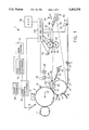
- FIG. 1 is a schematic side view of an image forming apparatus.
- FIG. 2 is a top view of an image bearing receiving sheet and a receiving sheet engaging device.
- an image forming apparatus 1 includes an image member, for example, a photoconductive drum 3, on which toner images are formed conventionally. More specifically, the surface of drum 3 is uniformly charged by a charger 5 and imagewise exposed by exposing means, for example, a laser 6 to create a series of electrostatic images. Each of the electrostatic images is toned by the application of a different colored toner using a toning device 7 which contains four toning stations indexible through toning relation with image member 3.
- a toning device 7 which contains four toning stations indexible through toning relation with image member 3.
- Transfer member 11 is shown as a drum, but could also be an endless belt, both of which are well known in the art for this application.
- the leading edge of the receiving sheet 31 is gripped by a suitable holding means, for example, gripping fingers 13.
- a vacuum or electrostatics could also be used.
- an electric field created by a transfer corona 17 or other field generating means transfers one of the toner images to the receiving sheet.
- transfer member 11 is continually rotated, the series of different color toner images are transferred in registration to the receiving sheet to create a multicolor image on the sheet.
- the receiving sheet is separated from the transfer member 11 by a pivotable skive 19 which is moved into a position against transfer member 11 by a solenoid 20.
- Image member 3 is continually cleaned by a cleaning device 8 so that the process is continuous.
- the receiving sheet 31 with the toner image on one side is now fed to a fuser 40 where a pair of fusing members 44 and 45, for example, conventional rollers internally heated by heaters 48 and 49, apply both pressure and heat to the image to at least partially fix it to the receiving sheet.
- a pair of fusing members 44 and 45 for example, conventional rollers internally heated by heaters 48 and 49, apply both pressure and heat to the image to at least partially fix it to the receiving sheet.
- a photographic picture can be scanned and combined with graphics already in memory or composed on a screen and a typed in message to form a combined image using a printer also comparable to the color copier identified above.
- One of the applications suggested for this system is the formation of customized greeting cards in which a portion of an image can come from the scanning of a photograph, another portion can come from suitable background or other graphics stored in memory particularly suitable to greeting cards, and still another portion can be typed in (or graphics composed) at a workstation.
- This patent application is hereby incorporated by reference herein.
- sheet engaging devices 29 and 30 preferably include a shaft 32 carrying a pair of rollers 35 which engage the toner side of the sheet in margins 34 designed to permit such engagement without adverse affect on a loose toner image. More specifically, a proposed toner image 33 is sized to fit on a receiving sheet 31 with significant margins 34 at each intrack side. Thus, if the receiving sheet is moved in the intrack direction of the arrow in FIG. 2, the rollers 35 can engage the toner side of the sheet in the margins 34 (generally parallel to the intrack direction) without disturbing toner image 33 which has not yet been fixed.
- First sheet engaging device 29 is positioned just downstream of a set of corona chargers 23 (whose function will be described below). When a normal stiffness receiving sheet is separated by separation skive 19 from transfer member 11, it substantially follows the path of the upper surface of skive 19 toward fuser 40 because it is peeled off transfer member 11. However, a stiff receiving sheet has a tendency when separated by skive 19 to rotate upward toward corona charger 23. Any contact with charger 23 can disturb the image. Accordingly, first sheet engaging device 29 is positioned to intercept the leading portion of a stiff receiving sheet and prevent it from engaging charger 23. Because of the configuration of the image on the sheet providing margins 34, engaging device 29 does not affect the image. Engaging device 29 need not have a pair of rollers but could be stationary, non-rotatable guide pieces that are positioned to also engage margins 34.
- Second sheet engaging devices 30 are positioned upstream of transfer corona 17 to urge the receiving sheet against transfer member 11 as it approaches the transfer area. Unlike the first sheet engaging device 29, the second sheet engaging device 30 is spring urged into contact with the transfer member.
- any immediate separation by the separation skive 19 is assisted by the beam strength of the sheet and the sheet has the tendency mentioned above of flapping up into the charger 23.
- separation can extend back into the transfer nip. It, thus, becomes desirable to attempt to hold the sheet to the transfer member rather than encourage its release.
- the AC corona is eliminated and a DC potential of the same polarity as the transfer corona 17 and of polarity opposite that of the toner image is applied by both chargers 22 and 23.
- a logic and control 100 is programmed to provide this adjustment between the two conditions of the chargers 22 and 23.
- Paper supply 15 can be loaded by cartridge, with a machine readable coding 54 indicative of the stiffness of the receiving sheets in the cartridge. Coding 54 actuates a sensor 56 which signals logic and control 100 that stiff paper is in paper supply 15. Logic and control 100 then removes the AC voltage from the chargers 22 and 23 during separation of the sheet from transfer member 11 and inverts the polarity of the DC voltage applied by these chargers.
- fuser 40 includes a first fusing member 44 which contacts the toner image to be fused and a second fusing member 45 which forms a heated pressure nip with the first fusing member 44.
- Both members are, in fact, rollers which are internally heated by a heating means 48 and 49. They are driven by a conventional motor 42 which has at least two speeds. Typically, a two speed motor is used in such fuser so that the fuser can be slowed for fusing transparency stock where more heat is necessary.
- a heavier weight receiving sheet coming from transfer member 11 reduces the temperature in the nip upon contact with the rollers substantially more than a normal sheet of paper would reduce it. This effect is pronounced in paper receiving sheets in excess of 40 pound bond weight (150 grams per square meter), especially 60 pound (225 grams per square meter) stock or thicker.
- the reduction in temperature sends a signal to the logic and control 100 to apply heat through heating means 48 and 49 according to a program adapted to the particular fuser 40 being used.
- the amount of heat added and temperature set points can be adjusted for the heavier stock.
- there is a lag in the recovery that is quite substantial with a thick receiving sheet.
- This problem is alleviated by utilizing the two speed drive embodied in motor 42 to drive the fusing rollers 44 and 45 at a first speed for the first revolution of the fusing roller contacting the image, first roller 44.
- the speed of the fuser is abruptly reduced to compensate for the now cooled portion of the fusing roller beginning to contact the toner image.
- the reduction in speed greatly increases the heat applied to the toner which compensates for the cooling of the surface by the first rotation in contact with the thick receiving sheet.
- Timing can be accomplished in a number of ways.
- a sensor 50 can be positioned a distance downstream of the nip equal to the circumference of first fusing roller 44. Actuation of the sensor 50 causes an immediate reduction in the speed of the motor 42. The reduction in speed could also be controlled in response to the abrupt reduction in temperature combined with knowledge of the rotation of roller 44.
- a preferred timing approach is to utilize a sensor 52 already in the nip to provide jam detection. The speed is then reduced a predetermined time after actuation of sensor 52. The time is, of course, dependent on the first speed and the circumference of roller 44.
- the speed of the fuser (both fast and slow) can be adjusted according to the weight of the paper.
- the sensing device 56 can again be used to slow the fuser when going between regular 20 pound bond paper and 60 pound bond paper.
- image forming apparatus 1 for making greeting cards, it is assumed that the copy after appropriate trimming will be folded. For example, it may be folded in the center, making a four page card which would commonly have greetings, messages and pictures on the first three pages. With the use of photos and other extensive broad coloring for such cards, it is common that one of the pages will have a substantially more dense image than the page adjacent it on the other side of the fold. It is desirable that the more dense portion of the image receive the most reliable heavy fusing to provide the gloss desired for it, as well as to make sure that toner stacks are fully fused. Reliability in this respect can be assisted by feeding the sheet into the fuser with the most dense portion leading. The most dense portion of the image then is less affected by the cooling of the fusing rollers from contact with the sheet. Such image orientation can be accomplished by rotating both images electronically or by hand at the composing stage.
- a receiving sheet In duplex copying with a receiving sheet path such as that shown in FIG. 1, a receiving sheet must pass through the fuser 40 twice.
- the first toner image passes through the fuser twice while the second toner image only passes through once. It is generally known to reduce the amount of heat used in the first passage, for example, by speeding up the fuser, to a minimum amount to allow the sheet to be handled without smearing of the image.
- the heat is then increased for the second pass to finish the fusing of the first image and complete the entire fusing of the second image.
- the first image will receive more heat in its two passes through the fuser than will the second image. Assuming that the texture of the surfaces of the rollers 44 and 45 are comparable, the first image will have a higher gloss than the second image.
- This aspect of the FIG. 1 apparatus can be managed and even taken advantage of in forming the images.
- greetings cards are a particularly good example.
- Particularly sophisticated customized greeting cards may use more than one photo.
- customization is also useful when no photos are being used.
- a very common and attractive utilization of customization in greeting cards involves the combination of a single photo with other greeting card graphics, including a customized message, a background and perhaps other decoration or drawings.
- the other image may be indifferent to gloss or even prefer a more matte finish.
- the image forming apparatus shown in FIG. 1 in which one toner image receives more fusing heat than does the other toner image, it is important to choose which image to form first.
- this feature can be utilized in an image forming apparatus that does not have a duplex path such as path 60 but in which duplex images are made by hand refeeding of the receiving sheet.
- the operator is given instructions to choose the image the operator prefers to be most glossy to form first.
- the receiving sheet is removed from output tray 64 and placed in the top of paper supply 15 with the first image up.
- the receiving sheet then passes through the system again receiving the second image on the second side (downside in the paper supply) and the first image receives a second fusing that improves its gloss when it passes through the fuser.
- OCP 90 operator control panel
- present operator control panels include display screens which will step-by-step lead an operator through a complex process with a copier or printer. If the operator decides to do duplex color with image forming apparatus 1, that information is input through OCP 90. OCP 90 then instructs the operator to compose first the image to have the highest gloss. After that image has been formed and fused, the operator is instructed to remove it from the output hopper 64 and place it first imageside faceup in paper supply 15 for copying a second side which the operator is advised is the "more matte" side.
- This basic instruction can be modified in many ways. For example, instead of suggesting that the glossy side be done first, the operator can be instructed to do the side with the photographic image first. The detail of the instruction would clearly depend on the expected sophistication of the operator.
- FIG. 1 illustrates several alternative approaches to electronic image formation, each of which can be adapted to the other features of the apparatus.
- the front end electronics are essentially the same as that on the Kodak ColorEdge 1550 Plus color is copier, referred to above, and on other available commercial image forming apparatus.
- the image is composed by hand for a color scanner 95, the output of which is used with minimal electronic manipulation to control laser 6 in image formation.
- a greeting card with a combination of photo, message and other graphics can be made on such apparatus by cutting and pasting with one side being input through color scanner 95 in a single operation.
- the prompting from OCP 90 mentioned above is appropriate to such an apparatus.
- FIG. 1 A more sophisticated approach is also shown in FIG. 1 using a workstation 74 and page composition electronics 72 for composing each multicolor image for feeding to laser control electronics 70.
- the image combining techniques disclosed in the above U.S. patent application to Watkins et al are particularly usable to form images that combine messages, other graphics and photographic images into a single multicolor image.
- suitable prompts to the operator at the workstation 74 suggesting that the image that is preferably most glossy be formed first, will assure the desired result with that image passing through fuser 40 twice.
- a preferred approach to such prompts would give the operator a choice between a glossy or a matte finish for the sides in question.
- One aspect of customization is to provide the customer with what he desires. In this instance, the customer may prefer to have the photographic image more matte and the other image more glossy. In such a case, the photographic side would be made last.
- the page composition electronics necessarily contains information associated with the makeup of each of both images. If only one of the images contains information from color scanner 95, that fact is necessarily known to page composition electronics 72. Page composition electronics 72 can then feed that page to laser control electronics 70 first. Other priorities can also be used. If both images contain material from color scanner 95, page composition electronics can be programmed to determine which material from color scanner 95 makes up the largest portion of its image.
- Another preference useful in some situations is to determine which image has the most large areas of a single color without detail.
- the extra fusing in making the first image glossy helps hide any grain shown in such areas.
- image analysis for such a characteristic is used to determine which image should be formed first.
- Sophisticated electronics is also available and can analyze a color image and distinguish the portion which has a photographic origin from the portion which is text or other graphics.
- Such image analysis could be used, not only in the more sophisticated approach using workstation 74 and page composition electronics 72, but also in the more basic approach in which the output of color scanner 95 is fed directly to laser control electronics and page composition is accomplished by cut and paste.
Abstract
Description
Claims (10)
Priority Applications (1)
| Application Number | Priority Date | Filing Date | Title |
|---|---|---|---|
| US08/281,281 US5493378A (en) | 1994-07-27 | 1994-07-27 | Image forming apparatus having a multispeed heated pressure fuser and method of use |
Applications Claiming Priority (1)
| Application Number | Priority Date | Filing Date | Title |
|---|---|---|---|
| US08/281,281 US5493378A (en) | 1994-07-27 | 1994-07-27 | Image forming apparatus having a multispeed heated pressure fuser and method of use |
Publications (1)
| Publication Number | Publication Date |
|---|---|
| US5493378A true US5493378A (en) | 1996-02-20 |
Family
ID=23076651
Family Applications (1)
| Application Number | Title | Priority Date | Filing Date |
|---|---|---|---|
| US08/281,281 Expired - Lifetime US5493378A (en) | 1994-07-27 | 1994-07-27 | Image forming apparatus having a multispeed heated pressure fuser and method of use |
Country Status (1)
| Country | Link |
|---|---|
| US (1) | US5493378A (en) |
Cited By (23)
| Publication number | Priority date | Publication date | Assignee | Title |
|---|---|---|---|---|
| US5629762A (en) * | 1995-06-07 | 1997-05-13 | Eastman Kodak Company | Image forming apparatus having a duplex path and/or an inverter |
| US5729820A (en) * | 1996-06-11 | 1998-03-17 | Eastman Kodak Company | Method and apparatus for producing high quality greeting cards or the like |
| US5809368A (en) * | 1996-01-12 | 1998-09-15 | Canon Kabushiki Kaisha | Image forming apparatus capable of forming an image having a plurality of colors on a light-transmitting recording material |
| US5853892A (en) * | 1996-06-28 | 1998-12-29 | Eastman Kodak Company | Amorphous fluoropolymer coated fusing belt |
| EP0892323A2 (en) * | 1997-07-14 | 1999-01-20 | Seiko Epson Corporation | Image forming apparatus |
| US5904871A (en) * | 1995-10-19 | 1999-05-18 | Canon Kabushiki Kaisha | Image heating device |
| US5956543A (en) * | 1998-11-20 | 1999-09-21 | Eastman Kodak Company | Fusing apparatus providing tuning of image gloss to match gloss of receiver member |
| US6061544A (en) * | 1998-11-20 | 2000-05-09 | Eastman Kodak Company | Maximizing image gloss uniformity by minimizing the effect of temperature droop in a fuser for reproduction apparatus |
| US6088567A (en) * | 1997-08-04 | 2000-07-11 | Canon Kabushiki Kaisha | Image forming device with different fixing speeds |
| US6101345A (en) * | 1997-03-14 | 2000-08-08 | Agfa-Gevaert | Method for gloss control in an electrographic apparatus |
| US6438336B1 (en) * | 2001-02-02 | 2002-08-20 | Hewlett-Packard Company | Method and apparatus for varying gloss level for individual elements printed on a single page |
| US20040022551A1 (en) * | 2002-07-31 | 2004-02-05 | Canon Kabushiki Kaisha | Printing apparatus |
| US20050084276A1 (en) * | 2003-10-20 | 2005-04-21 | Mark Hirst | Indicating system |
| US20050158087A1 (en) * | 2004-01-16 | 2005-07-21 | Eastman Kodak Company | Heater roller cleaner, method and apparatus for a fuser assembly |
| US20050214010A1 (en) * | 2004-03-25 | 2005-09-29 | Kietzman John W | Method of determining a relative speed between independently driven members in an image forming apparatus |
| US20050254848A1 (en) * | 2004-05-13 | 2005-11-17 | Lexmark International, Inc. | Method of operating an image forming apparatus using information stored in a fuser memory |
| US20120114356A1 (en) * | 2010-11-09 | 2012-05-10 | Fuji Xerox Co., Ltd. | Image forming apparatus |
| US20120321333A1 (en) * | 2011-06-16 | 2012-12-20 | Fuji Xerox Co., Ltd. | Fixing device, heating device, and image forming apparatus |
| CN103692799A (en) * | 2012-09-27 | 2014-04-02 | 图像电子公司 | Method and apparatus for variable gloss reduction |
| CN103692799B (en) * | 2012-09-27 | 2016-11-30 | 图像电子公司 | Method and apparatus for variable gloss reduction |
| US10088793B2 (en) * | 2017-01-16 | 2018-10-02 | Kabushiki Kaisha Toshiba | Post-processing apparatus and control method for controlling the post-processing apparatus |
| US10114307B2 (en) | 2012-09-27 | 2018-10-30 | Electronics For Imaging, Inc. | Method and apparatus for variable gloss reduction |
| JP2018205639A (en) * | 2017-06-08 | 2018-12-27 | 株式会社リコー | Fixing device and image forming apparatus |
Citations (6)
| Publication number | Priority date | Publication date | Assignee | Title |
|---|---|---|---|---|
| US4319874A (en) * | 1980-10-28 | 1982-03-16 | Xerox Corporation | Fuser apparatus and control therefore |
| US4595279A (en) * | 1983-10-06 | 1986-06-17 | Konishiroku Photo Ind. Co., Ltd. | Recording apparatus with speed control |
| US5249024A (en) * | 1990-07-05 | 1993-09-28 | Canon Kabushiki Kaisha | Image forming apparatus including fixing means with variable fixing speed |
| US5260751A (en) * | 1991-10-09 | 1993-11-09 | Canon Kabushiki Kaisha | Image forming apparatus with variable speed recording material carrying means |
| US5300995A (en) * | 1991-06-06 | 1994-04-05 | Sharp Kabushiki Kaisha | Fixing unit for controlling the moving speed of the fixing section |
| US5331384A (en) * | 1989-01-25 | 1994-07-19 | Canon Kabushiki Kaisha | Fixing apparatus having temperature controller which controls temperature according to width size and number of recording sheets |
-
1994
- 1994-07-27 US US08/281,281 patent/US5493378A/en not_active Expired - Lifetime
Patent Citations (6)
| Publication number | Priority date | Publication date | Assignee | Title |
|---|---|---|---|---|
| US4319874A (en) * | 1980-10-28 | 1982-03-16 | Xerox Corporation | Fuser apparatus and control therefore |
| US4595279A (en) * | 1983-10-06 | 1986-06-17 | Konishiroku Photo Ind. Co., Ltd. | Recording apparatus with speed control |
| US5331384A (en) * | 1989-01-25 | 1994-07-19 | Canon Kabushiki Kaisha | Fixing apparatus having temperature controller which controls temperature according to width size and number of recording sheets |
| US5249024A (en) * | 1990-07-05 | 1993-09-28 | Canon Kabushiki Kaisha | Image forming apparatus including fixing means with variable fixing speed |
| US5300995A (en) * | 1991-06-06 | 1994-04-05 | Sharp Kabushiki Kaisha | Fixing unit for controlling the moving speed of the fixing section |
| US5260751A (en) * | 1991-10-09 | 1993-11-09 | Canon Kabushiki Kaisha | Image forming apparatus with variable speed recording material carrying means |
Non-Patent Citations (1)
| Title |
|---|
| U.S. patent application Ser. No. 08/231,073, Watkins et al., filed Apr. 22, 1994. * |
Cited By (38)
| Publication number | Priority date | Publication date | Assignee | Title |
|---|---|---|---|---|
| US5629762A (en) * | 1995-06-07 | 1997-05-13 | Eastman Kodak Company | Image forming apparatus having a duplex path and/or an inverter |
| US5904871A (en) * | 1995-10-19 | 1999-05-18 | Canon Kabushiki Kaisha | Image heating device |
| US5809368A (en) * | 1996-01-12 | 1998-09-15 | Canon Kabushiki Kaisha | Image forming apparatus capable of forming an image having a plurality of colors on a light-transmitting recording material |
| AU721416B2 (en) * | 1996-06-11 | 2000-07-06 | Eastman Kodak Company | Method and apparatus for producing high quality greeting cards or the like |
| US5729820A (en) * | 1996-06-11 | 1998-03-17 | Eastman Kodak Company | Method and apparatus for producing high quality greeting cards or the like |
| US5853892A (en) * | 1996-06-28 | 1998-12-29 | Eastman Kodak Company | Amorphous fluoropolymer coated fusing belt |
| US6101345A (en) * | 1997-03-14 | 2000-08-08 | Agfa-Gevaert | Method for gloss control in an electrographic apparatus |
| EP0892323A2 (en) * | 1997-07-14 | 1999-01-20 | Seiko Epson Corporation | Image forming apparatus |
| EP0892323A3 (en) * | 1997-07-14 | 2002-06-19 | Seiko Epson Corporation | Image forming apparatus |
| US6088567A (en) * | 1997-08-04 | 2000-07-11 | Canon Kabushiki Kaisha | Image forming device with different fixing speeds |
| US5956543A (en) * | 1998-11-20 | 1999-09-21 | Eastman Kodak Company | Fusing apparatus providing tuning of image gloss to match gloss of receiver member |
| US6061544A (en) * | 1998-11-20 | 2000-05-09 | Eastman Kodak Company | Maximizing image gloss uniformity by minimizing the effect of temperature droop in a fuser for reproduction apparatus |
| US6438336B1 (en) * | 2001-02-02 | 2002-08-20 | Hewlett-Packard Company | Method and apparatus for varying gloss level for individual elements printed on a single page |
| US20040022551A1 (en) * | 2002-07-31 | 2004-02-05 | Canon Kabushiki Kaisha | Printing apparatus |
| US6885834B2 (en) * | 2002-07-31 | 2005-04-26 | Canon Kabushiki Kaisha | Printing apparatus |
| US7103292B2 (en) | 2003-10-20 | 2006-09-05 | Hewlett-Packard Development Company, L.P. | Heat indicating system |
| US20050084276A1 (en) * | 2003-10-20 | 2005-04-21 | Mark Hirst | Indicating system |
| US20050158087A1 (en) * | 2004-01-16 | 2005-07-21 | Eastman Kodak Company | Heater roller cleaner, method and apparatus for a fuser assembly |
| US7248826B2 (en) | 2004-01-16 | 2007-07-24 | Eastman Kodak Company | Heater roller cleaner, method and apparatus for a fuser assembly |
| US20050214010A1 (en) * | 2004-03-25 | 2005-09-29 | Kietzman John W | Method of determining a relative speed between independently driven members in an image forming apparatus |
| US7050734B2 (en) | 2004-03-25 | 2006-05-23 | Lexmark International, Inc. | Method of determining a relative speed between independently driven members in an image forming apparatus |
| US20050254848A1 (en) * | 2004-05-13 | 2005-11-17 | Lexmark International, Inc. | Method of operating an image forming apparatus using information stored in a fuser memory |
| US7149449B2 (en) | 2004-05-13 | 2006-12-12 | Lexmark International, Inc. | Method of determining a relative speed between independently driven members in an image forming apparatus |
| US20050254847A1 (en) * | 2004-05-13 | 2005-11-17 | Kietzman John W | Method of determining a relative speed between independently driven members in an image forming apparatus |
| US7035564B2 (en) | 2004-05-13 | 2006-04-25 | Lexmark International, Inc. | Method of operating an image forming apparatus using information stored in a fuser memory |
| US20120114356A1 (en) * | 2010-11-09 | 2012-05-10 | Fuji Xerox Co., Ltd. | Image forming apparatus |
| US8655212B2 (en) * | 2010-11-09 | 2014-02-18 | Fuji Xerox Co., Ltd. | Image forming apparatus that controls a transporting velocity of a transporter |
| US8805226B2 (en) * | 2011-06-16 | 2014-08-12 | Fuji Xerox Co., Ltd. | Fixing device having fixing-member moving unit, heating device having fixing-member moving unit, and image forming apparatus having fixing-member moving unit |
| US20120321333A1 (en) * | 2011-06-16 | 2012-12-20 | Fuji Xerox Co., Ltd. | Fixing device, heating device, and image forming apparatus |
| CN103692799B (en) * | 2012-09-27 | 2016-11-30 | 图像电子公司 | Method and apparatus for variable gloss reduction |
| CN103692799A (en) * | 2012-09-27 | 2014-04-02 | 图像电子公司 | Method and apparatus for variable gloss reduction |
| US9952539B2 (en) * | 2012-09-27 | 2018-04-24 | Electronics For Imaging, Inc. | Method and apparatus for variable gloss reduction |
| US10114307B2 (en) | 2012-09-27 | 2018-10-30 | Electronics For Imaging, Inc. | Method and apparatus for variable gloss reduction |
| US11022906B2 (en) | 2012-09-27 | 2021-06-01 | Electronics For Imaging, Inc. | Method and apparatus for variable gloss reduction |
| US11086246B2 (en) | 2012-09-27 | 2021-08-10 | Electronics For Imaging, Inc. | Method and apparatus for variable gloss reduction |
| US11169462B2 (en) | 2012-09-27 | 2021-11-09 | Electronics For Imaging, Inc. | Method and apparatus for variable gloss reduction |
| US10088793B2 (en) * | 2017-01-16 | 2018-10-02 | Kabushiki Kaisha Toshiba | Post-processing apparatus and control method for controlling the post-processing apparatus |
| JP2018205639A (en) * | 2017-06-08 | 2018-12-27 | 株式会社リコー | Fixing device and image forming apparatus |
Similar Documents
| Publication | Publication Date | Title |
|---|---|---|
| US5493378A (en) | Image forming apparatus having a multispeed heated pressure fuser and method of use | |
| US5126797A (en) | Method and apparatus for laminating toner images on receiving sheets | |
| US5581339A (en) | Method of forming duplex toner images | |
| JPH0772695A (en) | Creation apparatus of pseudophotographic print | |
| JPS60243686A (en) | Controller for fixing apparatus of electrographic type printing press | |
| EP1793284B1 (en) | Image forming apparatus including heating and cooling devices for fixing a toner image on a recording sheet | |
| US5392104A (en) | Method and apparatus for creating colorgraphs having a photographic look and feel from images created electrostatographically | |
| JPS61122667A (en) | Fixing device for picture formation device | |
| JPH0756409A (en) | Formation of pseudo-photographic print | |
| AU721416B2 (en) | Method and apparatus for producing high quality greeting cards or the like | |
| US5585910A (en) | Image forming apparatus including relatively stiff receiving sheet control device | |
| JP4595683B2 (en) | Image forming apparatus | |
| US20120148274A1 (en) | Providing desired gloss to mixed media sheets | |
| JPH0656536B2 (en) | Heat fixing device | |
| EP0208324B1 (en) | Apparatus for producing tabs | |
| EP0917013B1 (en) | Image forming apparatus with improved sheet separation by control of the fogging amount of a back side printing | |
| EP0864943A1 (en) | Single-pass fusing of multi-layer duplex copies | |
| JPH05181339A (en) | Fixing device | |
| JP2003167450A (en) | Image forming apparatus | |
| JPH1048901A (en) | Image formation device | |
| US3958989A (en) | Transparency support material for electrophotographic process | |
| JPH05181383A (en) | Fixing device | |
| JPH07219292A (en) | Image forming device | |
| EP0644464A2 (en) | Simulated photographic prints using xerography | |
| JP3469184B2 (en) | Fixing unit temperature control device and image forming apparatus |
Legal Events
| Date | Code | Title | Description |
|---|---|---|---|
| AS | Assignment |
Owner name: EASTMAN KODAK COMPANY, NEW YORK Free format text: ASSIGNMENT OF ASSIGNORS INTEREST;ASSIGNORS:JAMZADEH, FERAYDOON S.;FLICK, JAMES R.;REED, DAVID J.;REEL/FRAME:007088/0812 Effective date: 19940727 |
|
| FEPP | Fee payment procedure |
Free format text: PAYOR NUMBER ASSIGNED (ORIGINAL EVENT CODE: ASPN); ENTITY STATUS OF PATENT OWNER: LARGE ENTITY |
|
| FEPP | Fee payment procedure |
Free format text: PAYER NUMBER DE-ASSIGNED (ORIGINAL EVENT CODE: RMPN); ENTITY STATUS OF PATENT OWNER: LARGE ENTITY Free format text: PAYOR NUMBER ASSIGNED (ORIGINAL EVENT CODE: ASPN); ENTITY STATUS OF PATENT OWNER: LARGE ENTITY |
|
| STCF | Information on status: patent grant |
Free format text: PATENTED CASE |
|
| FPAY | Fee payment |
Year of fee payment: 4 |
|
| FPAY | Fee payment |
Year of fee payment: 8 |
|
| FPAY | Fee payment |
Year of fee payment: 12 |
|
| AS | Assignment |
Owner name: CITICORP NORTH AMERICA, INC., AS AGENT, NEW YORK Free format text: SECURITY INTEREST;ASSIGNORS:EASTMAN KODAK COMPANY;PAKON, INC.;REEL/FRAME:028201/0420 Effective date: 20120215 |
|
| AS | Assignment |
Owner name: WILMINGTON TRUST, NATIONAL ASSOCIATION, AS AGENT, MINNESOTA Free format text: PATENT SECURITY AGREEMENT;ASSIGNORS:EASTMAN KODAK COMPANY;PAKON, INC.;REEL/FRAME:030122/0235 Effective date: 20130322 Owner name: WILMINGTON TRUST, NATIONAL ASSOCIATION, AS AGENT, Free format text: PATENT SECURITY AGREEMENT;ASSIGNORS:EASTMAN KODAK COMPANY;PAKON, INC.;REEL/FRAME:030122/0235 Effective date: 20130322 |
|
| AS | Assignment |
Owner name: BARCLAYS BANK PLC, AS ADMINISTRATIVE AGENT, NEW YORK Free format text: INTELLECTUAL PROPERTY SECURITY AGREEMENT (SECOND LIEN);ASSIGNORS:EASTMAN KODAK COMPANY;FAR EAST DEVELOPMENT LTD.;FPC INC.;AND OTHERS;REEL/FRAME:031159/0001 Effective date: 20130903 Owner name: JPMORGAN CHASE BANK, N.A., AS ADMINISTRATIVE, DELAWARE Free format text: INTELLECTUAL PROPERTY SECURITY AGREEMENT (FIRST LIEN);ASSIGNORS:EASTMAN KODAK COMPANY;FAR EAST DEVELOPMENT LTD.;FPC INC.;AND OTHERS;REEL/FRAME:031158/0001 Effective date: 20130903 Owner name: BARCLAYS BANK PLC, AS ADMINISTRATIVE AGENT, NEW YO Free format text: INTELLECTUAL PROPERTY SECURITY AGREEMENT (SECOND LIEN);ASSIGNORS:EASTMAN KODAK COMPANY;FAR EAST DEVELOPMENT LTD.;FPC INC.;AND OTHERS;REEL/FRAME:031159/0001 Effective date: 20130903 Owner name: JPMORGAN CHASE BANK, N.A., AS ADMINISTRATIVE, DELA Free format text: INTELLECTUAL PROPERTY SECURITY AGREEMENT (FIRST LIEN);ASSIGNORS:EASTMAN KODAK COMPANY;FAR EAST DEVELOPMENT LTD.;FPC INC.;AND OTHERS;REEL/FRAME:031158/0001 Effective date: 20130903 Owner name: PAKON, INC., NEW YORK Free format text: RELEASE OF SECURITY INTEREST IN PATENTS;ASSIGNORS:CITICORP NORTH AMERICA, INC., AS SENIOR DIP AGENT;WILMINGTON TRUST, NATIONAL ASSOCIATION, AS JUNIOR DIP AGENT;REEL/FRAME:031157/0451 Effective date: 20130903 Owner name: EASTMAN KODAK COMPANY, NEW YORK Free format text: RELEASE OF SECURITY INTEREST IN PATENTS;ASSIGNORS:CITICORP NORTH AMERICA, INC., AS SENIOR DIP AGENT;WILMINGTON TRUST, NATIONAL ASSOCIATION, AS JUNIOR DIP AGENT;REEL/FRAME:031157/0451 Effective date: 20130903 Owner name: BANK OF AMERICA N.A., AS AGENT, MASSACHUSETTS Free format text: INTELLECTUAL PROPERTY SECURITY AGREEMENT (ABL);ASSIGNORS:EASTMAN KODAK COMPANY;FAR EAST DEVELOPMENT LTD.;FPC INC.;AND OTHERS;REEL/FRAME:031162/0117 Effective date: 20130903 |
|
| AS | Assignment |
Owner name: EASTMAN KODAK COMPANY, NEW YORK Free format text: RELEASE BY SECURED PARTY;ASSIGNOR:BARCLAYS BANK PLC;REEL/FRAME:041656/0531 Effective date: 20170202 |
|
| AS | Assignment |
Owner name: KODAK PORTUGUESA LIMITED, NEW YORK Free format text: RELEASE BY SECURED PARTY;ASSIGNOR:JP MORGAN CHASE BANK, N.A., AS ADMINISTRATIVE AGENT;REEL/FRAME:049814/0001 Effective date: 20190617 Owner name: PAKON, INC., NEW YORK Free format text: RELEASE BY SECURED PARTY;ASSIGNOR:JP MORGAN CHASE BANK, N.A., AS ADMINISTRATIVE AGENT;REEL/FRAME:049814/0001 Effective date: 20190617 Owner name: KODAK (NEAR EAST), INC., NEW YORK Free format text: RELEASE BY SECURED PARTY;ASSIGNOR:JP MORGAN CHASE BANK, N.A., AS ADMINISTRATIVE AGENT;REEL/FRAME:049814/0001 Effective date: 20190617 Owner name: KODAK AMERICAS, LTD., NEW YORK Free format text: RELEASE BY SECURED PARTY;ASSIGNOR:JP MORGAN CHASE BANK, N.A., AS ADMINISTRATIVE AGENT;REEL/FRAME:049814/0001 Effective date: 20190617 Owner name: QUALEX, INC., NEW YORK Free format text: RELEASE BY SECURED PARTY;ASSIGNOR:JP MORGAN CHASE BANK, N.A., AS ADMINISTRATIVE AGENT;REEL/FRAME:049814/0001 Effective date: 20190617 Owner name: FPC, INC., NEW YORK Free format text: RELEASE BY SECURED PARTY;ASSIGNOR:JP MORGAN CHASE BANK, N.A., AS ADMINISTRATIVE AGENT;REEL/FRAME:049814/0001 Effective date: 20190617 Owner name: KODAK REALTY, INC., NEW YORK Free format text: RELEASE BY SECURED PARTY;ASSIGNOR:JP MORGAN CHASE BANK, N.A., AS ADMINISTRATIVE AGENT;REEL/FRAME:049814/0001 Effective date: 20190617 Owner name: NPEC, INC., NEW YORK Free format text: RELEASE BY SECURED PARTY;ASSIGNOR:JP MORGAN CHASE BANK, N.A., AS ADMINISTRATIVE AGENT;REEL/FRAME:049814/0001 Effective date: 20190617 Owner name: KODAK AVIATION LEASING LLC, NEW YORK Free format text: RELEASE BY SECURED PARTY;ASSIGNOR:JP MORGAN CHASE BANK, N.A., AS ADMINISTRATIVE AGENT;REEL/FRAME:049814/0001 Effective date: 20190617 Owner name: KODAK IMAGING NETWORK, INC., NEW YORK Free format text: RELEASE BY SECURED PARTY;ASSIGNOR:JP MORGAN CHASE BANK, N.A., AS ADMINISTRATIVE AGENT;REEL/FRAME:049814/0001 Effective date: 20190617 Owner name: KODAK PHILIPPINES, LTD., NEW YORK Free format text: RELEASE BY SECURED PARTY;ASSIGNOR:JP MORGAN CHASE BANK, N.A., AS ADMINISTRATIVE AGENT;REEL/FRAME:049814/0001 Effective date: 20190617 Owner name: LASER PACIFIC MEDIA CORPORATION, NEW YORK Free format text: RELEASE BY SECURED PARTY;ASSIGNOR:JP MORGAN CHASE BANK, N.A., AS ADMINISTRATIVE AGENT;REEL/FRAME:049814/0001 Effective date: 20190617 Owner name: CREO MANUFACTURING AMERICA LLC, NEW YORK Free format text: RELEASE BY SECURED PARTY;ASSIGNOR:JP MORGAN CHASE BANK, N.A., AS ADMINISTRATIVE AGENT;REEL/FRAME:049814/0001 Effective date: 20190617 Owner name: FAR EAST DEVELOPMENT LTD., NEW YORK Free format text: RELEASE BY SECURED PARTY;ASSIGNOR:JP MORGAN CHASE BANK, N.A., AS ADMINISTRATIVE AGENT;REEL/FRAME:049814/0001 Effective date: 20190617 Owner name: EASTMAN KODAK COMPANY, NEW YORK Free format text: RELEASE BY SECURED PARTY;ASSIGNOR:JP MORGAN CHASE BANK, N.A., AS ADMINISTRATIVE AGENT;REEL/FRAME:049814/0001 Effective date: 20190617 |
|
| AS | Assignment |
Owner name: FPC INC., NEW YORK Free format text: RELEASE BY SECURED PARTY;ASSIGNOR:BARCLAYS BANK PLC;REEL/FRAME:052773/0001 Effective date: 20170202 Owner name: KODAK PHILIPPINES LTD., NEW YORK Free format text: RELEASE BY SECURED PARTY;ASSIGNOR:BARCLAYS BANK PLC;REEL/FRAME:052773/0001 Effective date: 20170202 Owner name: FAR EAST DEVELOPMENT LTD., NEW YORK Free format text: RELEASE BY SECURED PARTY;ASSIGNOR:BARCLAYS BANK PLC;REEL/FRAME:052773/0001 Effective date: 20170202 Owner name: KODAK REALTY INC., NEW YORK Free format text: RELEASE BY SECURED PARTY;ASSIGNOR:BARCLAYS BANK PLC;REEL/FRAME:052773/0001 Effective date: 20170202 Owner name: NPEC INC., NEW YORK Free format text: RELEASE BY SECURED PARTY;ASSIGNOR:BARCLAYS BANK PLC;REEL/FRAME:052773/0001 Effective date: 20170202 Owner name: KODAK (NEAR EAST) INC., NEW YORK Free format text: RELEASE BY SECURED PARTY;ASSIGNOR:BARCLAYS BANK PLC;REEL/FRAME:052773/0001 Effective date: 20170202 Owner name: LASER PACIFIC MEDIA CORPORATION, NEW YORK Free format text: RELEASE BY SECURED PARTY;ASSIGNOR:BARCLAYS BANK PLC;REEL/FRAME:052773/0001 Effective date: 20170202 Owner name: QUALEX INC., NEW YORK Free format text: RELEASE BY SECURED PARTY;ASSIGNOR:BARCLAYS BANK PLC;REEL/FRAME:052773/0001 Effective date: 20170202 Owner name: KODAK AMERICAS LTD., NEW YORK Free format text: RELEASE BY SECURED PARTY;ASSIGNOR:BARCLAYS BANK PLC;REEL/FRAME:052773/0001 Effective date: 20170202 Owner name: EASTMAN KODAK COMPANY, NEW YORK Free format text: RELEASE BY SECURED PARTY;ASSIGNOR:BARCLAYS BANK PLC;REEL/FRAME:052773/0001 Effective date: 20170202 |