EP0741020B1 - Machine d'impression rotative comprenant un appareil de pliage à assemblage libre - Google Patents
Machine d'impression rotative comprenant un appareil de pliage à assemblage libre Download PDFInfo
- Publication number
- EP0741020B1 EP0741020B1 EP96810254A EP96810254A EP0741020B1 EP 0741020 B1 EP0741020 B1 EP 0741020B1 EP 96810254 A EP96810254 A EP 96810254A EP 96810254 A EP96810254 A EP 96810254A EP 0741020 B1 EP0741020 B1 EP 0741020B1
- Authority
- EP
- European Patent Office
- Prior art keywords
- folder
- rotary printing
- printing press
- press according
- cylinder
- Prior art date
- Legal status (The legal status is an assumption and is not a legal conclusion. Google has not performed a legal analysis and makes no representation as to the accuracy of the status listed.)
- Expired - Lifetime
Links
- 230000008878 coupling Effects 0.000 description 4
- 238000010168 coupling process Methods 0.000 description 4
- 238000005859 coupling reaction Methods 0.000 description 4
- 230000008901 benefit Effects 0.000 description 3
- 230000008859 change Effects 0.000 description 3
- 238000010276 construction Methods 0.000 description 3
- 238000009434 installation Methods 0.000 description 2
- 230000007246 mechanism Effects 0.000 description 2
- 230000009467 reduction Effects 0.000 description 2
- 230000001360 synchronised effect Effects 0.000 description 2
- 210000001520 comb Anatomy 0.000 description 1
- 238000000034 method Methods 0.000 description 1
Images


Classifications
-
- B—PERFORMING OPERATIONS; TRANSPORTING
- B65—CONVEYING; PACKING; STORING; HANDLING THIN OR FILAMENTARY MATERIAL
- B65H—HANDLING THIN OR FILAMENTARY MATERIAL, e.g. SHEETS, WEBS, CABLES
- B65H45/00—Folding thin material
- B65H45/12—Folding articles or webs with application of pressure to define or form crease lines
- B65H45/22—Longitudinal folders, i.e. for folding moving sheet material parallel to the direction of movement
- B65H45/221—Longitudinal folders, i.e. for folding moving sheet material parallel to the direction of movement incorporating folding triangles
- B65H45/225—Arrangements of folding triangles
-
- B—PERFORMING OPERATIONS; TRANSPORTING
- B41—PRINTING; LINING MACHINES; TYPEWRITERS; STAMPS
- B41F—PRINTING MACHINES OR PRESSES
- B41F13/00—Common details of rotary presses or machines
- B41F13/0008—Driving devices
-
- B—PERFORMING OPERATIONS; TRANSPORTING
- B41—PRINTING; LINING MACHINES; TYPEWRITERS; STAMPS
- B41F—PRINTING MACHINES OR PRESSES
- B41F13/00—Common details of rotary presses or machines
- B41F13/008—Mechanical features of drives, e.g. gears, clutches
-
- B—PERFORMING OPERATIONS; TRANSPORTING
- B41—PRINTING; LINING MACHINES; TYPEWRITERS; STAMPS
- B41F—PRINTING MACHINES OR PRESSES
- B41F13/00—Common details of rotary presses or machines
- B41F13/54—Auxiliary folding, cutting, collecting or depositing of sheets or webs
- B41F13/56—Folding or cutting
- B41F13/60—Folding or cutting crosswise
Definitions
- the invention relates to a rotary printing press with a Folding apparatus according to the preamble of claim 1.
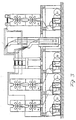
- FIG. 1 An example of a known drive, for example after DE 41 27 321 A1 is shown schematically in FIG. 1.
- the coupling from the longitudinal shaft 1.10 to the Folding apparatus comprising a knife cylinder 2, a collecting cylinder 3 and a jaw cylinder 4, mechanically a longitudinal shaft gear box 1, different tooth levels 1.20, a shaft 1.23 on a coupled with a bevel gear 1.24 Intermediate gear 1.3 or alternatively with a bevel gear 1.24 coupled knife cylinder 2.
- the cylinders 2, 3 and 4 are mechanically coupled with each other via spur gears.
- the disadvantage here is that the Cylinders 2, 3 and 4 to each other and to the longitudinal shaft 1.10 in the area of the backlash can take any position. The reason for this are effective on the cylinders Moments such as Curve controls or cutting stroke. Not through this avoidable irregularities are noticeable in the folding tolerances.
- a rotary printing press with at least one folder which is equipped with at least one own drive motor mechanically independent of at least printing units the printing press is driven from EP 0 567 741 A1, DE-A 2 046 131, GB 2 149 149 A, from "Deutscher Drucker” No. 14-15 from April 13, 1995, pages w46 ff, and from "Zeitungstechnik", December 1991, pages 78-80.
- the single drive from Finally, folding apparatus is also known from the subsequently published EP 0 699 524 A2.
- the invention has set itself the task of flexibility in terms of Configurability of a rotary printing press, as far as cutting, folding and laying out is affected to increase.
- the register setting should be prevented, at least at the same time Reduction of the folding inaccuracies due to the tooth play of the gears in the Drive train of the folder can be made individually for the folder can.
- the invention relates to a rotary printing press with at least one folder, the comprises at least one knife and one jaw cylinder and by equipment with at least one own drive motor mechanically independent of at least printing units the printing press is driven and can be independently set up and registered.
- the folder is arranged according to the invention at the roll changer level.
- the free one is Arrangement or adjustability of the folder to the printing units and advantageously also for a fold structure and a fold superstructure without incurring additional costs, possible.
- a first folder can be placed on the plant level, while a second folder is offset in the machine basement. As a result, short web transfer paths and unhindered access to the folders are achieved. If a fold structure and a fold superstructure are set up on the machine table, ie on the system level, the overall height is low.
- Both folders can also be set up in the basement as a double folder with a separate structure mounted on the machine table or as a double folder in a common superstructure. Both variants stand out because of the arrangement in the reel changer level due to its low overall height above the machine level out. Furthermore, because they are arranged on one level, they are particularly easy to use.
- the folder itself is movable. Will the fold structure and the superstructure is placed on a yoke, so a back-up folder, if such is intended to be inserted instead of the main folder if necessary.
- a back-up folder if such is intended to be inserted instead of the main folder if necessary.
- no additional space in the System needed. If the machine table itself is used as a yoke construction, and will be the folders in the basement, this also results in a low overall height.
- the fold structure and the fold superstructure on a yoke construction be movably arranged.
- the invention can be used particularly advantageously with the one disclosed in EP 0 644 048 A2 Combine drive and control concept.
- this document teaches that a pair of a printing and a Impression cylinder of a printing unit mechanically independent of other pairs of Printing and impression cylinders of the same printing unit and one printing cylinder each from its impression cylinder or impression cylinders mechanically independent should be driven.
- a drive motor drives via a mechanical one Coupling, preferably a motor-side pinion and a cylinder-side spur gear on the Jaw cylinder.
- a mechanical one Coupling preferably a motor-side pinion and a cylinder-side spur gear on the Jaw cylinder.
- Another variant is the drive motor there to arrange where, according to the prior art, the longitudinal shaft gear box sits.
- the Drive motor via a toothed belt on the knife cylinder.
- the mass of the knife cylinder can be low of the drive motor can be added, which increases the control dynamics can be improved.
- This can include a translation between drive motor and knife cylinder in more than one stage.
- the drive from the motor via a toothed belt is also preferred on the collecting cylinder.
- the mass of the Collecting cylinder which is larger than that of the knife cylinder, be added to the low own mass of the drive motor, which, as already mentioned, improves the control dynamics. In turn can a multi-stage translation between the drive motor and Collection cylinders may be preferred.
- Such a toothed belt can also be used on the jaw cylinder to be driven.
- the Drive drives the drive motor to any one via a toothed belt Gear in the entire drive train between the knife cylinder and delivery, for example a paddle wheel.
- the Drive also in operative connection with the drive train stationary idler gear. The required gear ratio from the drive motor to the gear is advantageous single-stage, so that again a space-saving solution is created.
- a printing web B runs through a capping device 20, a pair of pulling rollers 21 arranged behind, via a Collection cylinder 3 with assigned knife cylinder 2, there cut crosswise and then from the collecting cylinder 3 to the Folding jaw cylinder 4 and from there to a delivery device serve serving paddle wheel 5.
- the paddle wheel 5 can also be a means of transport that rotates endlessly between two rollers provided with grippers for the folded printed copies his.
- the jaw cylinder 4 driven directly by a drive motor 10.
- the mechanical coupling between the drive motor 10 and the The jaw cylinder 4 is driven by a pinion 10.1 and a cylinder-side spur gear 4.1 is formed.
- a printing press is shown, which is an example for gaining flexibility in terms of installation options of the self-powered folder.
- An exemplary embodiment is a folder F1 in the machine basement on the same level as reel changers R1, R2, R3 and R4 set up, while printing units Dl, D2 and D3 on one above horizontal plant level 100 are aligned one behind the other.
- a folder structure or folder superstructure 30 that opens one or more levels has at least one funnel, arranged and stored on the folder.
- the rebate superstructures 30, 40 are between the two printing units D2 and D3 arranged so that the printing webs run in from two sides.
- a second folder can be provided.
- This second folder is preferred also at the reel changer level or at the plant level 100, preferably approximately in alignment with the lower fold superstructure 30 arranged.
- the printing webs can optionally be fed to one of the folders become. In the example of Fig. 3, only that is in the engine room standing folder F1 in operation. If two Folders are provided, some of which are behind the Printing units further promoted printing webs, the folding structure, as shown by dashed lines as an example. From upper funnel of the folding structure 30 reach the longitudinally folded Printing webs then to the second folder, while the in lower hopper of the folding structure 30 folded printing webs continue to be fed to the first folder F1.
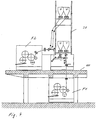
- Fig. 4 shows the installation of the second folder mentioned F2 at plant level 100.
- the first folder is again F1 in the machine cellar, on the same level as the not shown role changers placed while the second Laying out the F2 folder on one side of the machine next to the machine is arranged.
- the folding superstructure 30 and 40 with two vertically stacked double funnels T is in one Yoke J stored.
- the yoke J is itself in Fig. 4 on the Plant level 100 or the machine table above the first folder F1 and stored independently.
- Between the first Folder F1 and its part 30 of the folder superstructure is his Part of the folding structure with deflection and pull rollers in the same Yoke J added.
- the corresponding rebate component for the second folder F2 is located between the yoke J and the second folder F2.
- the Fold over component 40 for this second folder F2 added is located between the upper part of the yoke J.
- Fig. 5 shows two side by side on one level - on the machine table (not according to the invention) or folders arranged in the machine cellar F1, F2. Only the. first folder F1 is in operation while the second folder serves as a backup.
- the feeding of the printing web or webs to the folder F1 takes place again via a fold structure supported on a yoke J 30.
- the yoke J is independent of the folders F1 and F2 stored, thereby replacing the first folder F1 against the back-up folder F2 is made possible.
- the replacement of the folder F1 against is simple the back-up folder F2 if the two folders can be moved are (F1 ⁇ F1 'or F2 ⁇ F2').
- the printing press has six printing units D1 to D6 on, of which three printing units each seen in the web conveying direction arranged one behind the other and two such rows of three next to each other are set up.
- Left and right of the last one Printing unit D1 or D4 of the two rows of printing units are Folders F1, F2 and F3 placed so that one of the folders, F2, between the last two printing units D1 and D4 is arranged so that printing webs from these two printing units the one in the middle, in this case common Folder F2 can be fed.
- the two other folders F1, F2 and F3 are to the still free outsides of each of the Printing units D1 and D4 arranged.
- each of the folders F1, F2 and F3 is a assigned fold structure 30 with formers or formers, while above the two next to the folders F1 and F3 standing last printing units D1 and D4 the required deflection rollers and turning bars for feeding the printing webs are arranged.
- the folded printed copies can be displayed done uniformly in the machine longitudinal direction. But it can also, which in turn is the flexibility of the solution according to the invention demonstrated, in the case of the two outer folders F1 and F3 to the sides.
Landscapes
- Engineering & Computer Science (AREA)
- Mechanical Engineering (AREA)
- Folding Of Thin Sheet-Like Materials, Special Discharging Devices, And Others (AREA)
Claims (11)
- Machine d'impression rotative ayant au moins un appareil (F1, F2, F3) de pliage qui comporte au moins un cylindre (2) de coupe et un cylindre (4) de volet de pliage et, en étant équipée d'au moins un moteur (10) d'entraínement qui lui est propre, est entraínée mécaniquement indépendamment d'au moins des éléments (D1 à D6) d'imprimerie de la machine d'impression et peut être mise en place et indexée indépendamment de ceux-ci,
caractérisée en ce que
l'appareil (F1, F2, F3) de pliage est dans le plan de changeur de galets. - Machine d'impression rotative suivant la revendication 1, caractérisée en ce que la machine comporte un autre appareil (F2) de pliage et cet autre appareil (F2) de pliage est disposé dans un plan d'installation.
- Machine d'impression rotative suivant la revendication 1, caractérisée en ce qu'un premier appareil (F1) de pliage et un deuxième appareil (F2) de pliage sont disposés dans le plan de changeur de galets.
- Machine d'impression rotative suivant l'une des revendications précédentes, caractérisée en ce que la machine comporte un autre appareil de pliage et au moins l'un des appareils (F1, F2, F3) de pliage est mobile.
- Machine d'impression rotative suivant l'une des revendications précédentes, caractérisée en ce qu'une structure (30) de pliage est entraínée mécaniquement d'une manière indépendante de l'appareil (F1, F2, F3) de pliage.
- Machine d'impression rotative suivant la revendication précédente, caractérisée en ce qu'une structure (30) de pliage est entraínée mécaniquement d'une manière indépendante des éléments (D1 à D6) d'imprimerie.
- Machine d'impression rotative suivant l'une des revendications précédentes, caractérisée en ce qu'une structure (30) de pliage est montée indépendamment de son appareil (F1, F2) de pliage en aval.
- Machine d'impression rotative suivant la revendication précédente, caractérisée en ce que la structure (30) de pliage est montée dans le plan de la machine ou est surélevée sur un pont (J).
- Machine d'impression rotative suivant l'une des revendications précédentes, caractérisée en ce que la machine comprend un autre appareil de pliage et il est prévu une structure (30) de pliage pour plus d'un appareil (F1, F2, F3) de pliage.
- Machine d'impression rotative suivant l'une des revendications précédentes, caractérisée en ce qu'une paire d'un cylindre de pression et d'un cylindre de contrepression d'un élément (D1 à D6) d'imprimerie est entraínée mécaniquement d'une manière indépendante d'autres paires de cylindres de pression et de cylindres de contrepression du même élément (D1 à D6) d'imprimerie.
- Machine d'impression rotative suivant la revendication précédente, caractérisée en ce qu'un cylindre de pression est entraíné d'une manière mécaniquement indépendante également par son cylindre de contrepression ou par ses cylindres de contrepression.
Applications Claiming Priority (2)
| Application Number | Priority Date | Filing Date | Title |
|---|---|---|---|
| DE19516445A DE19516445A1 (de) | 1995-05-04 | 1995-05-04 | Rotationsdruckmaschine mit frei aufstellbarem Falzapparat |
| DE19516445 | 1995-05-04 |
Publications (4)
| Publication Number | Publication Date |
|---|---|
| EP0741020A2 EP0741020A2 (fr) | 1996-11-06 |
| EP0741020A3 EP0741020A3 (fr) | 1997-10-01 |
| EP0741020B1 true EP0741020B1 (fr) | 2000-06-28 |
| EP0741020B2 EP0741020B2 (fr) | 2005-11-16 |
Family
ID=7761111
Family Applications (1)
| Application Number | Title | Priority Date | Filing Date |
|---|---|---|---|
| EP96810254A Expired - Lifetime EP0741020B2 (fr) | 1995-05-04 | 1996-04-19 | Machine d'impression rotative comprenant un appareil de pliage à assemblage libre |
Country Status (4)
| Country | Link |
|---|---|
| US (1) | US5676056B1 (fr) |
| EP (1) | EP0741020B2 (fr) |
| DE (2) | DE19516445A1 (fr) |
| ES (1) | ES2150654T3 (fr) |
Cited By (1)
| Publication number | Priority date | Publication date | Assignee | Title |
|---|---|---|---|---|
| DE102006010602A1 (de) * | 2006-03-06 | 2007-09-20 | Maschinenfabrik Wifag | Falzvorrichtung mit auf unterschiedlichen Höhen angeordneten Falzapparaten |
Families Citing this family (33)
| Publication number | Priority date | Publication date | Assignee | Title |
|---|---|---|---|---|
| DE20221937U1 (de) | 1991-01-23 | 2009-06-18 | Koenig & Bauer Aktiengesellschaft | Rollenrotationsdruckmaschine |
| DE19719553A1 (de) * | 1997-05-09 | 1998-11-12 | Koenig & Bauer Albert Ag | Falzapparat |
| FR2774024B1 (fr) * | 1998-01-27 | 2000-04-14 | Heidelberger Druckmasch Ag | Plieuse d'une machine rotative a imprimer |
| US6306480B1 (en) * | 1998-03-27 | 2001-10-23 | Fort James Corporation | Single-ply dispenser napkin |
| US6422552B1 (en) | 1999-07-26 | 2002-07-23 | Heidelberger Druckmaschinen Ag | Movable folders and former board arrangement |
| US6152034A (en) * | 1999-07-26 | 2000-11-28 | Heidelberger Druckmaschinen, Ag | Former board arrangement in a web-fed rotary newspaper printing press |
| DE19959152A1 (de) * | 1999-12-08 | 2001-06-13 | Heidelberger Druckmasch Ag | Einrichtung zur Führung von Materialbahnen in Rotationsdruckmaschinen |
| DE10124977A1 (de) * | 2001-05-21 | 2002-11-28 | Roland Man Druckmasch | Antrieb für einen Zylinder einer Rotationsdruckmaschine |
| DE10131976B4 (de) | 2001-07-02 | 2005-12-29 | Koenig & Bauer Ag | Druckmaschine mit mehreren Sektionen |
| ATE452758T1 (de) * | 2001-10-05 | 2010-01-15 | Koenig & Bauer Ag | Vorrichtung zur verarbeitung einer bahn, verfahren zur erzeugung eines falzproduktes in einer rollenrotationsdruckmaschine und eine rollenrotationsdruckmaschine |
| DE10236864B4 (de) | 2002-08-12 | 2007-02-01 | Koenig & Bauer Ag | Heatset-Druckmaschine |
| DE10238010B4 (de) * | 2002-08-20 | 2006-04-13 | Man Roland Druckmaschinen Ag | Falzeinheit für Rollenrotationsdruckmaschinen mit kombinierter Zeitungs- und Selected Commercial-Produktion |
| DE502004008084D1 (de) * | 2003-04-23 | 2008-10-30 | Koenig & Bauer Ag | Rollenrotationsdruckmaschine |
| EP1708945B1 (fr) * | 2004-01-31 | 2012-07-04 | Koenig & Bauer AG | Presse comprenant au moins un element d'impression pour imprimer en offset une bande de matiere a imprimer avec une longueur de decoupe variable et une plieuse |
| DE102004021608A1 (de) * | 2004-01-31 | 2005-09-08 | Koenig & Bauer Ag | Druckmaschine mit zumindest einer Druckeinheit zum Bedrucken einer Bedruckstoffbahn im Offsetdruck mit variabler Abschnittslänge |
| DE102004051263A1 (de) * | 2004-10-21 | 2006-04-27 | Man Roland Druckmaschinen Ag | Druckmaschinenanordnung |
| DE102004060725A1 (de) * | 2004-12-17 | 2006-06-22 | Man Roland Druckmaschinen Ag | Wendestangeneinheit für eine Rollenrotationsdruckmaschine |
| EP1888337A1 (fr) * | 2005-04-19 | 2008-02-20 | Koenig & Bauer AG | Installation de machines a imprimer |
| DE102005037730B4 (de) * | 2005-04-19 | 2007-02-15 | Koenig & Bauer Ag | Druckmaschinen |
| WO2006111521A1 (fr) * | 2005-04-19 | 2006-10-26 | Koenig & Bauer Aktiengesellschaft | Installations de machines a imprimer et machines a imprimer |
| DE102005024282B4 (de) * | 2005-05-27 | 2012-11-08 | Koenig & Bauer Aktiengesellschaft | Rollenrotationsdruckmaschine |
| CN101213079B (zh) * | 2005-08-18 | 2010-06-09 | 柯尼格及包尔公开股份有限公司 | 印刷机设备 |
| CN101213080B (zh) * | 2005-08-18 | 2010-05-19 | 柯尼格及包尔公开股份有限公司 | 印刷机设备 |
| DE102005039395A1 (de) * | 2005-08-20 | 2007-02-22 | Man Roland Druckmaschinen Ag | Falzapparat einer Rollendruckmaschine |
| DE102006038638A1 (de) | 2005-12-15 | 2007-06-28 | Koenig & Bauer Aktiengesellschaft | Druckmaschinenanlage |
| US7926421B2 (en) | 2005-12-15 | 2011-04-19 | Koenig & Bauer Aktiengesellschaft | Printing press system |
| DE102007000517A1 (de) | 2007-10-17 | 2009-04-23 | Koenig & Bauer Aktiengesellschaft | Rotationsdruckmaschine |
| BRPI0910414B1 (pt) * | 2008-03-27 | 2019-05-14 | Pressline Services, Inc | Método para reduzir comprimento de corte de um jornal |
| US8210103B2 (en) * | 2008-05-23 | 2012-07-03 | Goss International Americas, Inc. | Apparatus and method for supplying ribbons to a former |
| WO2009150054A1 (fr) * | 2008-05-28 | 2009-12-17 | Koenig & Bauer Aktiengesellschaft | Presse offset rotative et procédé pour faire fonctionner la presse offset rotative |
| DE202009007737U1 (de) | 2009-05-30 | 2009-08-27 | Manroland Ag | Kompakte Rollenrotationsdruckanlage |
| DE102009045602A1 (de) | 2009-09-04 | 2011-03-10 | Manroland Ag | Kompakte Rollenrotationsdruckanlage |
| DE102009029572B4 (de) | 2009-09-18 | 2022-09-08 | Manroland Goss Web Systems Gmbh | Rollenrotationsdruckanlage für mehrfachbreite Bahnen mit einfachbreitem Falzapparat |
Family Cites Families (19)
| Publication number | Priority date | Publication date | Assignee | Title |
|---|---|---|---|---|
| DE1919695A1 (de) † | 1969-04-18 | 1970-11-05 | Koenig & Bauer Schnellpressfab | Austauschbares Falzwerk fuer variable Rollen-Rotationsdruckmaschinen |
| JPS5019971B1 (fr) * | 1970-01-14 | 1975-07-11 | ||
| SE7504029L (sv) * | 1975-04-08 | 1976-10-09 | Wifag Maschf | Falsapparat med sasom kasett utbytbar falsmekanism |
| SE7702541L (sv) * | 1977-03-07 | 1978-09-08 | Wifag Maschf | Sett och anordning att endra pappersformatet pa tryckmaskiner |
| CH628855A5 (fr) * | 1978-04-03 | 1982-03-31 | Fobelmac Sprl | Procede pour acheminer et traiter ou travailler en continu une bande souple pour produire des documents et installation pour sa mise en oeuvre. |
| DE2846191C3 (de) * | 1978-10-24 | 1981-08-13 | Koenig & Bauer AG, 8700 Würzburg | Falzapparat für Rollenrotationsdruckmaschinen |
| DE3237504C2 (de) † | 1982-10-09 | 1985-07-11 | Koenig & Bauer AG, 8700 Würzburg | Papierbahnführung in Rollenrotationsdruckmaschinen |
| DE3422755C2 (de) * | 1984-06-20 | 1986-06-19 | Koenig & Bauer AG, 8700 Würzburg | Falzapparat für Buchfalzungen an einer Rollenrotationsdruckmaschine |
| GB8611722D0 (en) * | 1986-05-14 | 1986-06-25 | Drg Uk Ltd | Processing paper & other webs |
| US4671501A (en) † | 1986-06-23 | 1987-06-09 | Kabushiki Kaisha Tokyo Kikai Seisakusho | Turning-bar-less folding machine of W-width rotary press |
| DE3626287C3 (de) * | 1986-08-02 | 1997-04-03 | Koenig & Bauer Albert Ag | Falzapparat |
| DE4012396A1 (de) † | 1990-04-19 | 1991-10-31 | Roland Man Druckmasch | Druckmaschinenanlage |
| DE4127321C2 (de) * | 1991-08-17 | 1999-01-07 | Roland Man Druckmasch | Antrieb für eine Rollen-Rotationsdruckmaschine |
| FR2680480B1 (fr) * | 1991-08-19 | 1993-11-26 | Harris Marinoni Sa | Machine a couper et a plier une bande de papier imprime. |
| DE4214394C2 (de) * | 1992-04-30 | 1998-08-20 | Asea Brown Boveri | Antriebsvorrichtung für eine längswellenlose Rotationsdruckmaschine |
| JP3197974B2 (ja) * | 1993-03-19 | 2001-08-13 | 東芝機械株式会社 | 可変サイズ折機 |
| US5405127A (en) * | 1993-04-14 | 1995-04-11 | Didde Web Press Corporation | Signature folder apparatus for web fed printing press with sheet stop adjustment |
| DE4318299A1 (de) * | 1993-06-02 | 1994-12-08 | Roland Man Druckmasch | Einziehvorrichtung und Verfahren zum Einzug von Materialbahnen in eine Druckmaschine |
| DE4430693B4 (de) * | 1994-08-30 | 2005-12-22 | Man Roland Druckmaschinen Ag | Antriebe für eine Rollenrotations-Offsetdruckmaschine |
-
1995
- 1995-05-04 DE DE19516445A patent/DE19516445A1/de not_active Withdrawn
-
1996
- 1996-04-19 EP EP96810254A patent/EP0741020B2/fr not_active Expired - Lifetime
- 1996-04-19 ES ES96810254T patent/ES2150654T3/es not_active Expired - Lifetime
- 1996-04-19 DE DE59605480T patent/DE59605480D1/de not_active Expired - Lifetime
- 1996-05-03 US US08642465 patent/US5676056B1/en not_active Expired - Fee Related
Non-Patent Citations (2)
| Title |
|---|
| BORIS FUCHS: "Rotationsmaschinenantrieb ohne Längswelle - eine Wiederentdeckung von Hamada", ZEITUNGSTECHNIK, 31 December 1991 (1991-12-31), pages 78 - 80 * |
| DIPL.-ING. BORIS FUCHS: "Color-Management-Systeme, Computer-to-plate und wellenlos angetriebene Achtertürme ...", DEUTSCHER DRUCKER, vol. 14-15, 13 April 1995 (1995-04-13), pages W46 - W53 * |
Cited By (1)
| Publication number | Priority date | Publication date | Assignee | Title |
|---|---|---|---|---|
| DE102006010602A1 (de) * | 2006-03-06 | 2007-09-20 | Maschinenfabrik Wifag | Falzvorrichtung mit auf unterschiedlichen Höhen angeordneten Falzapparaten |
Also Published As
| Publication number | Publication date |
|---|---|
| EP0741020B2 (fr) | 2005-11-16 |
| EP0741020A2 (fr) | 1996-11-06 |
| EP0741020A3 (fr) | 1997-10-01 |
| ES2150654T3 (es) | 2000-12-01 |
| DE59605480D1 (de) | 2000-08-03 |
| US5676056A (en) | 1997-10-14 |
| US5676056B1 (en) | 2000-07-11 |
| DE19516445A1 (de) | 1996-11-07 |
Similar Documents
| Publication | Publication Date | Title |
|---|---|---|
| EP0741020B1 (fr) | Machine d'impression rotative comprenant un appareil de pliage à assemblage libre | |
| EP0741019B1 (fr) | Appareil de pliage entraíné individuellement pour une machine d'impression rotative | |
| DE4405658C2 (de) | Antrieb für Zylinder einer Rollenrotationsdruckmaschine | |
| DE19852438A1 (de) | Druckwerk für eine Rollenrotationsdruckmaschine | |
| EP1493563A2 (fr) | Machine d'impression offset | |
| EP0059357A1 (fr) | Plieuse | |
| EP0469311B1 (fr) | Appareil de pliage pour machine d'impression rotative | |
| DE19856422C2 (de) | Warenbahnzuführung zu einem Falzwerk | |
| EP1007461B1 (fr) | Plieuse a poches comportant deux ou trois poches de pliage | |
| EP0332794B1 (fr) | Dispositif pour amener des feuilles de papier individuelles au cylindre de pression d'une machine de bureau, notamment d'une imprimante à matrice | |
| DD142435A5 (de) | Mehrfarbendruckmaschine | |
| DE19610900A1 (de) | Falzapparat mit einem heftebildenden Zusatzmodul | |
| DE4344896C5 (de) | Antrieb für Zylinder einer Rollenrotationsdruckmaschine | |
| DE10163209B4 (de) | Vorrichtung zur Herstellung von Falzprodukten | |
| DE2725030A1 (de) | Antriebsvorrichtung fuer ein umstellbares satellitendruckwerk | |
| DE1752276A1 (de) | Einrichtung zum Zufuehren eines Bandes od.dgl.zu einer Bearbeitungsmaschine,wie insbesondere einer Presse od.dgl. | |
| EP1351872B1 (fr) | Dispositif pour distribuer ou recevoir des feuillets individuels | |
| DE9312170U1 (de) | Falzapparat für Rollenrotationsdruckmaschinen | |
| WO1992001620A1 (fr) | Canal de guidage | |
| CH686426A5 (de) | Druckpresse mit aneinander anstellbaren Drucktuchzylindern. | |
| DD153473A3 (de) | Vorrichtung zur steuerung der falzklappen eines falzklappenzylinders | |
| DE19943031C5 (de) | Getriebe zum Antrieb einer Druckmaschine | |
| DE4036023C2 (fr) | ||
| DE688907C (de) | Stauchfalzmaschine zum Parallelfalzen | |
| DE452779C (de) | Lagerung der Zylinder einer Rotationsdruckmaschine |
Legal Events
| Date | Code | Title | Description |
|---|---|---|---|
| PUAI | Public reference made under article 153(3) epc to a published international application that has entered the european phase |
Free format text: ORIGINAL CODE: 0009012 |
|
| AK | Designated contracting states |
Kind code of ref document: A2 Designated state(s): BE CH DE ES FI FR GB IT LI NL SE |
|
| PUAL | Search report despatched |
Free format text: ORIGINAL CODE: 0009013 |
|
| AK | Designated contracting states |
Kind code of ref document: A3 Designated state(s): BE CH DE ES FI FR GB IT LI NL SE |
|
| 17P | Request for examination filed |
Effective date: 19980303 |
|
| 17Q | First examination report despatched |
Effective date: 19980708 |
|
| GRAG | Despatch of communication of intention to grant |
Free format text: ORIGINAL CODE: EPIDOS AGRA |
|
| GRAG | Despatch of communication of intention to grant |
Free format text: ORIGINAL CODE: EPIDOS AGRA |
|
| GRAH | Despatch of communication of intention to grant a patent |
Free format text: ORIGINAL CODE: EPIDOS IGRA |
|
| GRAH | Despatch of communication of intention to grant a patent |
Free format text: ORIGINAL CODE: EPIDOS IGRA |
|
| GRAA | (expected) grant |
Free format text: ORIGINAL CODE: 0009210 |
|
| AK | Designated contracting states |
Kind code of ref document: B1 Designated state(s): BE CH DE ES FI FR GB IT LI NL SE |
|
| PG25 | Lapsed in a contracting state [announced via postgrant information from national office to epo] |
Ref country code: NL Free format text: LAPSE BECAUSE OF FAILURE TO SUBMIT A TRANSLATION OF THE DESCRIPTION OR TO PAY THE FEE WITHIN THE PRESCRIBED TIME-LIMIT Effective date: 20000628 |
|
| REG | Reference to a national code |
Ref country code: CH Ref legal event code: EP |
|
| GBT | Gb: translation of ep patent filed (gb section 77(6)(a)/1977) |
Effective date: 20000630 |
|
| REF | Corresponds to: |
Ref document number: 59605480 Country of ref document: DE Date of ref document: 20000803 |
|
| ET | Fr: translation filed | ||
| ITF | It: translation for a ep patent filed | ||
| REG | Reference to a national code |
Ref country code: ES Ref legal event code: FG2A Ref document number: 2150654 Country of ref document: ES Kind code of ref document: T3 |
|
| PLBI | Opposition filed |
Free format text: ORIGINAL CODE: 0009260 |
|
| PLBQ | Unpublished change to opponent data |
Free format text: ORIGINAL CODE: EPIDOS OPPO |
|
| PLAB | Opposition data, opponent's data or that of the opponent's representative modified |
Free format text: ORIGINAL CODE: 0009299OPPO |
|
| PLBF | Reply of patent proprietor to notice(s) of opposition |
Free format text: ORIGINAL CODE: EPIDOS OBSO |
|
| 26 | Opposition filed |
Opponent name: HEIDELBERGER DRUCKMASCHINEN AG Effective date: 20010328 Opponent name: MAN ROLAND DRUCKMASCHINEN AG Effective date: 20010328 Opponent name: KOENIG & BAUER AKTIENGESELLSCHAFT -LIZENZEN-PATENT Effective date: 20010327 |
|
| R26 | Opposition filed (corrected) |
Opponent name: KOENIG & BAUER AKTIENGESELLSCHAFT -LIZENZEN-PATENT Effective date: 20010327 |
|
| NLR1 | Nl: opposition has been filed with the epo |
Opponent name: HEIDELBERGER DRUCKMASCHINEN AG Opponent name: MAN ROLAND DRUCKMASCHINEN AG Opponent name: KOENIG & BAUER AKTIENGESELLSCHAFT -LIZENZEN-PATENT |
|
| PLBF | Reply of patent proprietor to notice(s) of opposition |
Free format text: ORIGINAL CODE: EPIDOS OBSO |
|
| PLBF | Reply of patent proprietor to notice(s) of opposition |
Free format text: ORIGINAL CODE: EPIDOS OBSO |
|
| REG | Reference to a national code |
Ref country code: GB Ref legal event code: IF02 |
|
| PLAW | Interlocutory decision in opposition |
Free format text: ORIGINAL CODE: EPIDOS IDOP |
|
| APAC | Appeal dossier modified |
Free format text: ORIGINAL CODE: EPIDOS NOAPO |
|
| APAC | Appeal dossier modified |
Free format text: ORIGINAL CODE: EPIDOS NOAPO |
|
| APAC | Appeal dossier modified |
Free format text: ORIGINAL CODE: EPIDOS NOAPO |
|
| PLAB | Opposition data, opponent's data or that of the opponent's representative modified |
Free format text: ORIGINAL CODE: 0009299OPPO |
|
| PLBQ | Unpublished change to opponent data |
Free format text: ORIGINAL CODE: EPIDOS OPPO |
|
| PLAB | Opposition data, opponent's data or that of the opponent's representative modified |
Free format text: ORIGINAL CODE: 0009299OPPO |
|
| PLBQ | Unpublished change to opponent data |
Free format text: ORIGINAL CODE: EPIDOS OPPO |
|
| R26 | Opposition filed (corrected) |
Opponent name: HEIDELBERGER DRUCKMASCHINEN AG Effective date: 20010328 Opponent name: MAN ROLAND DRUCKMASCHINEN AG Effective date: 20010328 Opponent name: KOENIG & BAUER AKTIENGESELLSCHAFT -LIZENZEN-PA Effective date: 20010327 |
|
| APAA | Appeal reference recorded |
Free format text: ORIGINAL CODE: EPIDOS REFN |
|
| R26 | Opposition filed (corrected) |
Opponent name: HEIDELBERGER DRUCKMASCHINEN AG Effective date: 20010328 Opponent name: MAN ROLAND DRUCKMASCHINEN AG Effective date: 20010328 Opponent name: KOENIG & BAUER AKTIENGESELLSCHAFT -LIZENZEN-PA Effective date: 20010327 |
|
| NLR1 | Nl: opposition has been filed with the epo |
Opponent name: HEIDELBERGER DRUCKMASCHINEN AG Opponent name: MAN ROLAND DRUCKMASCHINEN AG Opponent name: KOENIG & BAUER AKTIENGESELLSCHAFT -LIZENZEN-PATENT |
|
| APBU | Appeal procedure closed |
Free format text: ORIGINAL CODE: EPIDOSNNOA9O |
|
| PGFP | Annual fee paid to national office [announced via postgrant information from national office to epo] |
Ref country code: NL Payment date: 20050418 Year of fee payment: 10 |
|
| PGFP | Annual fee paid to national office [announced via postgrant information from national office to epo] |
Ref country code: FI Payment date: 20050421 Year of fee payment: 10 Ref country code: ES Payment date: 20050421 Year of fee payment: 10 Ref country code: BE Payment date: 20050421 Year of fee payment: 10 |
|
| PGFP | Annual fee paid to national office [announced via postgrant information from national office to epo] |
Ref country code: SE Payment date: 20050422 Year of fee payment: 10 |
|
| PUAH | Patent maintained in amended form |
Free format text: ORIGINAL CODE: 0009272 |
|
| STAA | Information on the status of an ep patent application or granted ep patent |
Free format text: STATUS: PATENT MAINTAINED AS AMENDED |
|
| APAH | Appeal reference modified |
Free format text: ORIGINAL CODE: EPIDOSCREFNO |
|
| 27A | Patent maintained in amended form |
Effective date: 20051116 |
|
| AK | Designated contracting states |
Kind code of ref document: B2 Designated state(s): BE CH DE ES FI FR GB IT LI NL SE |
|
| REG | Reference to a national code |
Ref country code: CH Ref legal event code: AEN Free format text: AUFRECHTERHALTUNG DES PATENTES IN GEAENDERTER FORM |
|
| NLR2 | Nl: decision of opposition |
Effective date: 20051116 |
|
| PG25 | Lapsed in a contracting state [announced via postgrant information from national office to epo] |
Ref country code: ES Free format text: LAPSE BECAUSE OF FAILURE TO SUBMIT A TRANSLATION OF THE DESCRIPTION OR TO PAY THE FEE WITHIN THE PRESCRIBED TIME-LIMIT Effective date: 20060227 |
|
| GBTA | Gb: translation of amended ep patent filed (gb section 77(6)(b)/1977) | ||
| PG25 | Lapsed in a contracting state [announced via postgrant information from national office to epo] |
Ref country code: BE Free format text: LAPSE BECAUSE OF NON-PAYMENT OF DUE FEES Effective date: 20060430 |
|
| PGFP | Annual fee paid to national office [announced via postgrant information from national office to epo] |
Ref country code: IT Payment date: 20060430 Year of fee payment: 11 |
|
| NLV1 | Nl: lapsed or annulled due to failure to fulfill the requirements of art. 29p and 29m of the patents act | ||
| ET3 | Fr: translation filed ** decision concerning opposition | ||
| BERE | Be: lapsed |
Owner name: MASCHINENFABRIK *WIFAG Effective date: 20060430 |
|
| PG25 | Lapsed in a contracting state [announced via postgrant information from national office to epo] |
Ref country code: FI Free format text: LAPSE BECAUSE OF NON-PAYMENT OF DUE FEES Effective date: 20060419 |
|
| PG25 | Lapsed in a contracting state [announced via postgrant information from national office to epo] |
Ref country code: SE Free format text: LAPSE BECAUSE OF NON-PAYMENT OF DUE FEES Effective date: 20060420 |
|
| PG25 | Lapsed in a contracting state [announced via postgrant information from national office to epo] |
Ref country code: IT Free format text: LAPSE BECAUSE OF NON-PAYMENT OF DUE FEES Effective date: 20070419 |
|
| PGFP | Annual fee paid to national office [announced via postgrant information from national office to epo] |
Ref country code: GB Payment date: 20090424 Year of fee payment: 14 |
|
| GBPC | Gb: european patent ceased through non-payment of renewal fee |
Effective date: 20100419 |
|
| PG25 | Lapsed in a contracting state [announced via postgrant information from national office to epo] |
Ref country code: GB Free format text: LAPSE BECAUSE OF NON-PAYMENT OF DUE FEES Effective date: 20100419 |
|
| REG | Reference to a national code |
Ref country code: FR Ref legal event code: PLFP Year of fee payment: 20 |
|
| PGFP | Annual fee paid to national office [announced via postgrant information from national office to epo] |
Ref country code: DE Payment date: 20150422 Year of fee payment: 20 Ref country code: CH Payment date: 20150402 Year of fee payment: 20 |
|
| PGFP | Annual fee paid to national office [announced via postgrant information from national office to epo] |
Ref country code: FR Payment date: 20150422 Year of fee payment: 20 |
|
| REG | Reference to a national code |
Ref country code: DE Ref legal event code: R071 Ref document number: 59605480 Country of ref document: DE |
|
| REG | Reference to a national code |
Ref country code: CH Ref legal event code: PL |