EP0730973A2 - Appareil et méthode d'enregistrement - Google Patents
Appareil et méthode d'enregistrement Download PDFInfo
- Publication number
- EP0730973A2 EP0730973A2 EP96301499A EP96301499A EP0730973A2 EP 0730973 A2 EP0730973 A2 EP 0730973A2 EP 96301499 A EP96301499 A EP 96301499A EP 96301499 A EP96301499 A EP 96301499A EP 0730973 A2 EP0730973 A2 EP 0730973A2
- Authority
- EP
- European Patent Office
- Prior art keywords
- recording
- image
- scan
- sub
- scan direction
- Prior art date
- Legal status (The legal status is an assumption and is not a legal conclusion. Google has not performed a legal analysis and makes no representation as to the accuracy of the status listed.)
- Granted
Links
Images


Classifications
-
- B—PERFORMING OPERATIONS; TRANSPORTING
- B41—PRINTING; LINING MACHINES; TYPEWRITERS; STAMPS
- B41J—TYPEWRITERS; SELECTIVE PRINTING MECHANISMS, i.e. MECHANISMS PRINTING OTHERWISE THAN FROM A FORME; CORRECTION OF TYPOGRAPHICAL ERRORS
- B41J2/00—Typewriters or selective printing mechanisms characterised by the printing or marking process for which they are designed
- B41J2/005—Typewriters or selective printing mechanisms characterised by the printing or marking process for which they are designed characterised by bringing liquid or particles selectively into contact with a printing material
- B41J2/01—Ink jet
- B41J2/21—Ink jet for multi-colour printing
- B41J2/2132—Print quality control characterised by dot disposition, e.g. for reducing white stripes or banding
-
- G—PHYSICS
- G06—COMPUTING; CALCULATING OR COUNTING
- G06K—GRAPHICAL DATA READING; PRESENTATION OF DATA; RECORD CARRIERS; HANDLING RECORD CARRIERS
- G06K15/00—Arrangements for producing a permanent visual presentation of the output data, e.g. computer output printers
- G06K15/02—Arrangements for producing a permanent visual presentation of the output data, e.g. computer output printers using printers
- G06K15/10—Arrangements for producing a permanent visual presentation of the output data, e.g. computer output printers using printers by matrix printers
- G06K15/102—Arrangements for producing a permanent visual presentation of the output data, e.g. computer output printers using printers by matrix printers using ink jet print heads
- G06K15/105—Multipass or interlaced printing
- G06K15/107—Mask selection
-
- G—PHYSICS
- G06—COMPUTING; CALCULATING OR COUNTING
- G06K—GRAPHICAL DATA READING; PRESENTATION OF DATA; RECORD CARRIERS; HANDLING RECORD CARRIERS
- G06K2215/00—Arrangements for producing a permanent visual presentation of the output data
- G06K2215/0082—Architecture adapted for a particular function
- G06K2215/0094—Colour printing
Definitions
- the present invention relates to recording apparatus and method.
- An ink jet recording apparatus for printing (recording) an image by discharging ink to a recording medium has been known as an image recording apparatus.
- the ink jet recording apparatus is a non-impact type recording apparatus and characterized by small noise and easiness of recording a color image by the use of multiple colors, and it has been recently becoming popular rapidly.
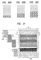
- Fig. 38 shows a schematic perspective view of a prior art ink jet recording apparatus.
- a rolled recording medium 5 is fed past convey rollers 1 and 2 and pinched by a feed roller 3 and fed in a direction f as a sub-scan motor 15 coupled to the feed motor 3 is driven.
- Guide rails 6 and 7 are arranged in parallel across the recording medium 5 and a recording head 9 mounted on a carriage 8 scans laterally.
- Four color heads 9Y, 9M, 9C and 9Bk for yellow, magenta, cyan and black each having a plurality of ink discharge ports arranged are mounted on the carriage 8 and four color ink tanks are arranged correspondingly thereto.
- the recording medium 5 is intermittently fed by a recording width of the recording head 9, and recording head 9 scans in a direction P to discharge ink droplets in accordance with a binary image signal while the recording material 5 stops.
- a characteristic of the recording medium is important, and particularly a spread or blur characteristic of the ink on the recording medium imparts a significant affect to an image quality.
- the spread factor of that recording medium is 3.0.
- the recording head 9 having a plurality of ink discharge ports arranged is scanned in a direction A to sequentially repeat the image recording of a width d in the order of (1), (2) and (3) as shown in each of Figs. 39A and 39B.
- the absorption of the ink by the recording medium is sufficient and the width of the recorded image is substantially equal to the record width d.
- the joint for each record scan does not cause a problem on the image as shown in Fig. 39A.
- the spread ⁇ d of the image width in the high density area changes with the spread factor of the recording medium and the amount of ink discharged to the recording medium, and the larger the spread factor is or the larger the amount of ink is, the larger is ⁇ d. Accordingly, in order to prevent the black stripe from appearing, it is necessary to use the recording medium having a small spread factor or reduce the amount of ink used for recording. In this case, however, the image quality is lowered and the massive and high quality image is not attained.
- a multi-scan system may be used to eliminate the black stripe.
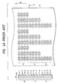
- a printing method representing the feature of the multi-scan system is shown in Fig. 40.
- a head 1 comprises three parts X, Y and Z having nozzles X-1 to X-4, Y-1 to Y-4 and Z-1 to Z-4, respectively.
- an image is printed with the 1/3 thinning in an area Z' on a sheet by the part Z of the head 1.
- the sheet is sub-scanned by d in the direction B and dots thinned by 1/3 and thinned by the part Z are printed by the part Y of the head in an area Y'.
- the sheet is sub-scanned by d in the direction B and dots thinned by the parts Y and Z are printed in an area X'. Since the printing is made such that the dots printed by the same nozzle do not continuously appear in the direction A, the disturbance of the image caused by the fluctuation of the ink droplets when they are discharged is not prominent.
- the term record as used herein includes the imparting of ink (printing, image forming and dying) to any ink support member to which ink is imparted such as cloth, string, paper or sheet, and the present invention is applicable not only to information processing industries but also to a wide variety of industrial fields including apparel industries in which the ink support members to which ink is imparted such as cloth, string, paper and sheet are used.
- image is used in its broad sense and represents characters, pictures, photographs, patterns and marks.
- Fig. 1 shows a state of recording scan of a color image of an image recording apparatus in one embodiment of the present invention.
- a record sheet passes through convey rollers 41 and 42 and is pinched by a feed roller 43.
- the feed roller (sheet feed roller) 43 is rotationally driven by a sheet feed motor 52 to feed a recording sheet 40 in a direction 44 as the sheet feed motor 52 is rotated by a sheet feed motor driver 61 in accordance with as sheet feed signal 62 from a control circuit 53.
- a guide shaft 46 is arranged in parallel to the recording sheet 40 across a portion 45 of the recording sheet 40 and a head unit 49 comprising a plurality (four) of recording heads mounted on a carriage 48 is laterally reciprocated as a carriage motor driver 58 rotatably drive the carriage motor 51 in accordance with a scan signal 59 from the control circuit 53 so that the recording scan is performed.
- the carriage 48 is reciprocally moved through a timing belt 47 by the carriage motor (pulse motor) 51.
- the head unit 49 on the carriage 48 has a cyan head 49C having cyan ink, a magenta head 49M having magenta ink, a yellow head 49Y having yellow ink and a black head 49Bk having black ink and an ink tank of a corresponding ink is connected to each of the heads.
- each head is of a type in which ink droplets are discharged by causing a change in status of ink by using a thermal energy.
- the recording sheet 45 is intermittently fed and while the recording sheet stops, the recording head 49 (carriage 48) discharges ink droplets in accordance with an image signal while it scans in a direction P.
- the control circuit 53 for controlling the recording operation outputs a reader control signal 55 for a reader unit (or a computer) 54.
- the reader unit 54 reads the image signal to be printed out in accordance with a request from the control circuit 53 and outputs it to an image processing circuit 56 as Y, M and C image signals.
- the image processing circuit 56 applies a predetermined image process to the Y, M and C image signals and outputs them as corresponding Y, M, C and Bk image signals.
- the control circuit 53 receives the image signals from the image processing circuit 56 as density signals to be outputted by the recording apparatus and the data is sent to a nozzle selection unit 70 through the control circuit 53 and the image signals are sent to the recording head 49.
- Fig. 2 shows a block diagram of a detailed configuration of the nozzle selection unit 70 of the present embodiment shown in Fig. 1.
- the image signal 106 sent from the control circuit 53 is sent to a nozzle selection circuit 105 where it is divided into a nozzle signal 107 which is an image signal corresponding to nozzle portions not conducting the multi-scan and nozzle signals 108 and 109 which are image signals corresponding to nozzle portions conducting the multi-scan.
- the nozzle signal 108 which is the image signal corresponding to the nozzle portions conducting the multi-scan is an image signal of a Z block which conducts the multi-scan
- the nozzle signal 109 is an image signal of an X block.
- the nozzle signal 107 which is the image signal of a Y block not conducting the multi-scan is supplied to the head 49.
- the nozzle signal 108 which is the image signal of the Z block conducting the multi-scan is outputted to an AND circuit 104 and the nozzle signal 109 which is the image signal of the X block is outputted to an NAND circuit 102.
- a pattern generation unit 71 thins the image signal and generates interpolation data and conducts those processes by using a filter table 101 to be described later.
- the filter table used by the pattern generation unit 71 is explained below.
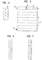
- Fig. 3 shows a model of the filter table 101 used by the pattern generation unit 71.
- the table provides an effect of a filter to attain dot arrangement which does not cause a black stripe.
- data is sequentially read by the filter table 101 by using a pattern 81.
- the image signal 108 synchronized with a clock signal 100 is also sequentially outputted and it is outputted to the head as the image signal 110 through the AND circuit 104.
- the pattern 81 is applied to the nozzles of the Z block for which the thinning is to be conducted
- '0' is sent from the filter table 101 to the AND circuit 104.
- the image signal 110 to the recording head 49 is '0' without regard to the image signal 108 and the printing is not conducted.
- the AND circuit 104 since the AND circuit 104 is used, the first three pixels are eliminated and the printing is conducted at the fourth pixel.
- the nozzles of the X block which conduct the interpolation of scan use the same filter as that used for the thinning and the image signal for the interpolation can be readily attained by the use of the NAND circuit 102.
- the data corresponding to the pattern 81 is applied to the NAND circuit 102 for the nozzles of the X block so that the printing is conducted by the Z-1 to Z-3 nozzles and the printing by the Z-4 nozzle is not conducted.
- Fig. 4 shows the order of use of the nozzles in the present embodiment.
- the printing is conducted in the X block to interpolate the dots thinned to one half in the pre-scan.
- the multi-scan is not conducted and the image is printed as it is.
- the dots are thinned to one half and printed.
- the sheet feed motor 52 is driven to feed the sheet by e (eight-nozzle length). By repeating the above, the image is formed.
- the number of nozzles for the multi-scan is not limited.
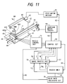
- Fig. 5 shows scan of the head when one image is formed.
- an arrow 30 indicates a scan direction of the head 35
- an arrow 31 indicates a feed direction of the sheet
- the Z block conducts the thinning at a position 32 shown by 0 and the interpolation by the X block is not conducted but the image data sent is printed as it is.
- the printing since the printing may be conducted without using specific nozzles, the discharge is free from fluctuation and a high quality of image is attained. Further, by conducting the recording scan by the four inks, cyan, magenta, yellow and black, a color image free from a black stripe can be formed.
- the second embodiment is intended to attain a higher quality of image than that attainable by the first embodiment described above.
- a plurality of filters for generating thinning and interpolation patterns are provided and a plurality of selectors are sequentially switched in the direction of scan to select the filters.
- a complex dot arrangement is attained with a number of filters.
- a filter table 101 which uses a filter as shown in Fig. 6 or Fig. 7 in the pattern generation unit 71 is used and they are sequentially switched in the scan direction so that the recording dots are arranged in a zig-zag (or checker) pattern and the adjacent pixels are printed in a plurality of runs.
- the plurality of filters are switched to generate the thinning and interpolation patterns so that an optimum pattern which eliminates the black stripe is formed. Even if a fluctuation occurs in the discharge in a particular nozzle, the continuous printing by one nozzle may be prevented by simply changing the filter and a high quality of image is attained.
- the third embodiment is intended to attain a higher quality of image than that attainable in the second embodiment.
- the third embodiment is the same configuration as that of the first embodiment shown in Fig. 1 except the construction of the nozzle selection unit 70 of Fig. 1.
- Fig. 8 shows a detailed block diagram of the nozzle selection unit 70 of the third embodiment of the present invention.
- the selector 103 is switched by using a synchronization signal 200 outputted from the control circuit 53.
- the filters since the data sent from the filter table 101 is sent in synchronism with the external clock signal 100, the filters, if there are a plurality of filters, are sequentially selected whether the image data is present or not and the same filter may be used by the adjacent pixels.
- the image synchronization signal 200 is used to control the switching of the selector 103.
- Fig. 9 shows an arrangement of patterns in the third embodiment.
- the selector is not switched at a portion 120 in which no image signal is present but it is switched when the next image signal is sent for printing out.
- the adjacent pixels are always outputted by using different filters and the formation of the adjacent pixels by the same nozzle does not occur. Therefore, even if the failure of discharge or fluctuation of discharge occurs in a particular nozzle, it does not affect to the image and a high quality of image is attained.
- a fourth embodiment attains a high quality printout by conducting the multi-scan of the nozzles at the end of the head as well as the multi-scan at the end of the image.
- a digital copying apparatus has a variety of edit functions.
- the image signals sent in two runs are printed by dividing one scan area into two parts.
- a diagram of the print control in the fourth embodiment is same as that shown in Fig. 1.
- a part 1 shown in Fig. 10 is printed in a first scan and a part 2 is printed in a second scan, and there is no gap between the two scanned images and a stripe 300 appears at the joint of the first scan and the second scan.
- Neighboring image data is eliminated immediately after the completion of the first scan and the image data at the start of the second scan is printed to interpolate the image data of the first scan. In this manner, the high quality of image free from the black stripe is attained.
- a white stripe may appear or a black stripe may not be eliminated depending on the spread factor of the recording medium.
- the filters for the thinning are prepared to fit to the recording media and they are selected so that the high quality of image free from the stripe for any recording medium is attained.
- the fifth embodiment is now explained.
- the high quality of image is attained by using means for detecting the spread.
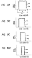
- Fig. 11 shows a perspective view of a color ink jet recording apparatus and a control unit therefor in the fifth embodiment of the present invention.
- the like elements to those of the first embodiment shown in Fig. 1 are designated by the like numerals and the detailed explanation thereof is omitted.
- a spread factor calculation circuit 75 for calculating a spread factor of ink when the ink is discharged to the recording medium is provided. The ink spread factor is calculated in the following manner.
- Fig. 11 record patterns 80 for calibrating parameters having different widths at several densities are printed on a recording sheet 81 fed by the feed roller 43.
- Fig. 12 shows an example of the record pattern for calibrating the parameters recorded on the recording sheet 81.
- the recording sheet 81 is mounted on a read position of the reader unit 54 and the read operation is started in the direction of 82, 83, 84 and 85.
- Figs. 13A to 13D show relations of the record pattern for calibrating the parameters to the input signal in the scan direction.
- Numerals 91a, 91b, 91c and 91d denote signals when the recording is made on a recording sheet which causes the spread or bleeding.
- a boundary line between the non-printed area and the printed area is broader.
- X1 denotes a signal read from the recording sheet having no spread.
- the spread parameter is calculated by the spread factor calculation circuit 75 and depending on the result thereof, a control signal 63 for selecting an optimum filter which allows the thinning method without causing the stripe from the plurality of filters is outputted so that the high quality of image free from the stripe is attained even if a change in the appearance of the stripe occurs due to a change in the spread by the change of an absorbing speed of the ink by the recording sheet or a change in the environment.
- thinning method which do not cause the stripe are shown in Figs. 14A to 14C.
- control is made such that the area of thinning is gradually changed as the spread of the recording medium increases.
- a higher quality of image may be attained.
- the appearance of the white stripe or the non-elimination of the white stripe is prevented even if the way of spread of the recording medium changes and the high quality of image free from the stripe is attained for any recording medium.
- the filters for thinning are automatically changed although the present embodiment is not limited thereto but more appropriate filters for the recording medium may be provided and they may be manually switched to attain the high quality of image free from the stripe for any recording medium.
- filters for the recording medium may be provided and they may be manually switched to attain the high quality of image free from the stripe for any recording medium.
- a filter is generated by using a spread parameter so that printout is attained by using an optimum filter without having a memory circuit for holding the filter table.
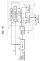
- Fig. 15 shows a block diagram of a detailed configuration of the nozzle selection unit 70 in the sixth embodiment.
- a filter generation circuit 111 is provided in the sixth embodiment.
- Other configuration is similar to that of the fifth embodiment shown in Fig. 11 and the detailed explanation thereof is omitted.
- a spread parameter signal 63 from the spread factor calculation circuit 75 is sent to the filter generation circuit 111 which generates an optimum filter having a characteristic as shown in Figs. 14A to 14C.
- the multi-scan may be conducted by using the generated optimum filter and the high quality of image is attained.
- the black stripe at the end due to the spread of ink is eliminated even if the manner of spread is different from recording medium to recording medium and the high quality of image is stably attained.
- the multi-scan is conducted only for the nozzles at the end for each scan.
- a difference in the density may appear between an area (a) in which normal printing is conducted and an area (b) in which the end multi-scan is conducted as shown in Fig. 16.
- This difference in the density is caused by a change in a depthwise position for holding the ink dye because of a difference in implantation time of the ink to the recording medium. Because of this phenomenon, the high quality of image is not attained although the end black stripe is eliminated.
- Fig. 17 shows a perspective view of a color ink jet recording apparatus and a control unit therefor of the seventh embodiment of the present invention.
- the like elements to those of the first embodiment shown in Fig. 1 are designated by the like numerals and the detailed explanation thereof is omitted.
- a table 73 which stores control data for controlling the image output signal to reduce the image density of the multi-scan area is provided.
- the order of use of the recording head 49 in the seventh embodiment is essentially same as that of the first embodiment shown in Fig. 4 and the scan of the head is that shown in Fig. 5. Further, the detailed configuration of the nozzle control unit 70 in the seventh embodiment is same as that of the third embodiment shown in Fig. 8. Thus, the explanation thereof is omitted and only the portions different from the above embodiments are explained below.
- Fig. 18 shows an example of model of the table 73 of the seventh embodiment.
- the table 73 provides an effect of filter for arranging dots such that a black stripe does not appear.
- the image processing circuit 56 controls the image output signal to lower the image density of the multi-scan area.
- the image signal is sent from the table 73 to the image processing circuit 56.
- a relation of the image input signal and the output signal as shown in Fig. 18 is applied only to the multi-scan area, and when the density of the end multi-scan area is high, the table (c) is used to conduct the printing with a lower density.
- the table 73 serves to reduce the change in the density due to the change in the absorption property of the ink and contains data of frequently used recording sheets.
- an optimum table is selected from the tables registered in the table 72 and the image data for recording is generated by using the image input/output signal from the selected table 73 and it is sent to the control circuit 53 so that the high quality of image free from end density irregularity is attained without lowering the print speed.
- the black stripe at the end due to the spread of the ink may be eliminated. Further, the irregularity of density caused by the partial multi-scan is suppressed and the stable high quality of image is attained.
- a pulse for a discharge heater is controlled to control the amount of discharge of ink so that the density is varied to attain a similar effect to that of the seventh embodiment.
- Fig. 19 shows a color ink jet recording apparatus and a control unit therefor of the eighth embodiment of the present invention.
- the like elements to those of the first embodiment shown in Fig. 1 are designated by the like numerals and the detailed explanation thereof is omitted.
- a pulse width control circuit 72 is provided between the nozzle control unit 70 and the recording head 49 in order to lower the image density of the multi-scan area.
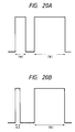
- Figs. 20A and 20B show timings for applying a drive pulse to the recording head 49.
- the head drive pulse in the print mode comprises a main pulse (b) for discharging and a sub-pulse (a) as shown in Fig. 20A.
- the width of the sub-pulse (a) is varied for the nozzle which conducts the end multi-scan in order to vary the amount of ink discharged to vary the density.
- the control signal 71 is sent from the nozzle control circuit 70 to the pulse width control circuit 72 and the printing is conducted in accordance with the control signal 71.
- the pulse width control circuit 72 when the end multi-scan is conducted, the sub-pulse (c) of Fig. 20B ((c) ⁇ (a)) by the pulse width control circuit 72 to reduce the density and suppress the irregularity of density in the multi-scan area.
- a ninth embodiment is constructed to effectively suppress the occurrence of the irregularity of density in the end multi-scan area depending on the recording medium, as compared with the seventh and eighth embodiments described above.
- Fig. 21 shows a perspective view of a color ink jet recording apparatus and a control unit therefor of the ninth embodiment of the present invention.
- the like elements to those of the eighth embodiment shown in Fig. 19 are designated by the like numerals and the detailed explanation thereof is omitted.
- a table 73 which holds a table shown in Fig. 18 and having the same function as that in the seventh embodiment and a medium detection unit 83 for detecting a medium by using an optical characteristic or a manual medium selection unit (not shown) are provided.
- a type signal 84 representing the medium type is sent from the medium detection unit 83 or the manual medium selection unit to the table 73, the table is selected in accordance with the signal, and the image signal 74 which suppress the irregularity of density is selected and fed back to the image processing circuit 56 to conduct the printing.
- the input/output image signal shown by (c) in Fig. 16 is selected, and when a medium which causes a low density is selected, the image input/output signal (a) is selected so that the high quality of image free from irregularity is stably attained without regard to the medium.
- the table to be selected are prepared for several types of sheets which are frequently used and a plurality of tables are prepared so that the irregularity of density is corrected even if there is a difference in the absorption of the respective sheets. By selecting those, the high quality of image free from irregularity of density is attained.
- control to suppress the irregularity of density for each medium is added to the eighth embodiment to attain the high quality of image free from the irregularity of density.
- Fig. 22 shows a perspective view of a color ink jet recording apparatus and a control unit therefor of the tenth embodiment of the present invention.
- the like elements to those of the eighth embodiment shown in Fig. 19 and the ninth embodiment shown in Fig. 21 are designated by the like numerals and the detailed explanation thereof is omitted.
- a table 73 similar to that of the seventh embodiment shown in Fig. 21 and a medium detection unit 83 for detecting a medium by using an optical characteristic or a manual medium detection unit (not shown) are provided.
- a type signal 84 representing a type of the medium is sent from the medium detection unit 83 or the manual medium detection unit (not shown) to the table 73, the table is selected in accordance with the signal, an image signal which suppresses the irregularity of density is selected, and the signal 76 is fed back to the pulse width control circuit 72 rather than to the image processing circuit 56 to control the drive pulse width for the recording head 59 for printing.
- the table 73 selects the pulse for suppressing the irregularity of density in accordance with the table selected by the type signal 84 of the recording medium from the medium detection unit 83 or the manual medium detection unit (not shown), and the selected signal 76 is sent to the pulse width control circuit 72 and the recording head 59 is driven in accordance with the selected pulse width for printing.
- Fig. 23 shows a relation between the pulse width of the drive pulse applied to the recording head 49 and the print density.
- the pulse width and the density exhibit a relation as shown in Fig. 22, and the calculation is made in accordance with the relation, the pulse width is set to attain the density which fits to the selected medium, and the output signal is applied to the heater of the nozzle in the multi-scan area to suppress the irregularity of density.
- a basic configuration is similar to that of the first embodiment shown in Fig. 1 except the configuration of the nozzle selection unit 70 of Fig. 1.
- Fig. 24 shows a block diagram of the nozzle control circuit 70 of the present embodiment.
- the image signal 106 sent from the control circuit 53 is divided by the nozzle selection circuit 105 to image signals 107 and 109 for the nozzles which conduct the multi-scan and an image signal 108 for the nozzle which do not conduct the multi-scan.
- the image signal 106 for the nozzles which does not conduct the multi-scan is supplied to the head, the image signal 107 of the nozzles of the Z block which conduct the multi-scan is supplied to the AND circuit 104, and the image signal 109 for the nozzles of the X block which conduct the multi-scan is supplied to the NAND circuit 102.
- Numeral 71 denotes a pattern generation unit for generating the thinning and interpolation data of the image signal and has a plurality of filter tables 101 as will be described later.
- Numeral 300 denotes a manual switching circuit for generating a signal 301 to select the filter table. It generates the signal 301 for selecting the filter table in accordance with a manual input from a key.
- FIG. 3 shows a model of the filter table 101.
- This table provides an effect of filter which arrange dots in a manner to prevent the occurrence of a black stripe.
- a pattern 81 shown in Figs. 25A to 25C comprises a data pattern of '0', '0', '0' and '1' from the top to the bottom, and the data is sequentially read from the top and outputted to the circuit 102 and 104.
- the image signal synchronized with the clock signal is sequentially outputted to the AND circuit 102 and it is outputted as the image signal for the nozzles of the Z block through the AND circuit 104.
- the data is sequentially read from the pattern 81, and when the data is '0', the image signal is not outputted from the AND circuit 104 and the nozzles in the Z block do not discharge the ink.
- the data is '1', the image signal is outputted from the AND circuit 104 and the nozzles of the Z block discharge the ink to record the image. Accordingly, by using the pattern 81, the image formed by the nozzles of the Z block is thinned by the three pixels in the scan direction of the head and the recording is made at the fourth pixel, and it is repeated.
- the signal read from the pattern 81 is applied to the NAND circuit together with the image signal 109 for the nozzles of the X block so that the image formed by the nozzles of the X block is recorded by three pixels in the scan direction of the head and the fourth pixel is eliminated. Namely, the dot eliminated by the nozzles of the Z block is interpolated.
- a white stripe may appear on the recorded image or a black stripe may not be eliminated and the effect by the multi-scan may not be attained.
- the multi-scan is conducted by using the same filter table 101 as that use when the image data having a low density is inputted, the effect is not attained sufficiently.
- the selector circuit 103 switches the filter table 101 in accordance with the signal sent from the manual switching circuit 200 of Fig. 24.
- the filter table 101 which is switched in accordance with the density of the document sheet may be set such that the thinning area increases as the image density increases, as shown in Figs. 25A to 25C.
- the dots are eliminated in the direction of arrangement (direction of nozzle column) as they are in a twelfth embodiment to be described later.
- dots are thinned in the direction of nozzles of the head while in the eleventh embodiment described above, the dots are thinned in the direction of scan of the head.
- the pattern 81 of Fig. 3 is used as the table of the filter table 101 as it is in the eleventh embodiment and the data of the pattern 81 is sequentially read from the top and it is applied to the circuits 104 and 102 of Fig. 24.
- the image signals 107 of the nozzles Z-1, Z-2, Z-3 and Z-4 of the Z block are applied, the data '0', '0', '0' and '1' are read from the table 101.
- the data '0' is sent from the filter table 101 to the AND circuit 104 so that the image signal of the Z-1 nozzle is '0' and the recording is not made by the Z-1 nozzle.
- the Z-2, Z-3 and Z-4 nozzles are sent from the nozzle selection circuit 105.
- the data '1' is sent from the filter table 101 to the AND circuit 104 and the Z-4 nozzle conducts the recording in accordance with the image signal. Because of the AND circuit 104, the first three pixels are eliminated in the direction of the column of the nozzles and the recording is made at the fourth pixel.
- the filter table 101 used for thinning the image data for the nozzles of the Z block is used and the data read from the table 101 and the image signal 109 of the nozzles of the X block are applied to the NAND circuit 102 so that the interpolation signal is readily derived.
- the filter table 101 is used and means for detecting the density from the image data is used to change the filter table 101 in accordance with the image data to attain the high quality of image.
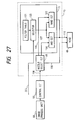
- Fig. 26 shows a color ink jet recording apparatus and a control unit therefor of the thirteenth embodiment of the present invention.
- Fig. 26 one scan of image data sent from a host computer or the reader unit 54 is temporarily stored in a buffer memory 30.
- the record density is calculated by the image processing circuit 56 based on the image data for the nozzles in the vicinity of the end of the head and the signal 201 reflecting the calculation is sent to the nozzle control circuit 70 and the filter table 101 in the nozzle control circuit 70 is selected.
- Fig. 27 shows a block diagram of the nozzle control circuit of the present embodiment.
- the signal 201 sent from the image processing circuit 56 is sent to the selector 103 and the selector 103 selects the filter to be used from the filter table 101 and the signal from the selected filter is sent to the AND circuit 104 and the NAND circuit 102.
- the high quality of image is attained by selecting the optimum filter on real time basis even if the density of the image data changes.
- the dots injected into the matrix are randomly eliminated to attain a high quality of image.
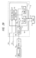
- Fig. 28 shows a color ink jet recording apparatus and a control unit therefor of the present embodiment.
- Fig. 28 one scan of image data sent from the host computer or the reader unit 54 is temporarily stored in the buffer memory 30.
- the record density is calculated by the image processing circuit 56 based on the image data for the nozzles in the vicinity of the end of the recording head 49 and a matrix to be described later is assembled by a matrix generation circuit 31 based on the calculation result and the content thereof is outputted as a signal 202.
- the circuit 31 also generates a random number and sends it to the nozzle control circuit 70 together with the signal 202.
- Fig. 29 shows a block diagram of the nozzle control circuit 70.
- the signal 202 sent from the matrix generation circuit 31 is applied to the filter table 101 and the matrix for the signal 202 and the filter of the filter table 101 are combined in a manner to be described later and the combined content is outputted to the selector 103.
- the selector 103 switches the filter in accordance with the image density data by the signal 201 sent from the image processing circuit 56.
- a matrix of 2 x 2 (dots) is assembled.
- two 2 x 2 (dots) matrices are arranged in the direction of the column of nozzles.
- the high quality of image is attained by the effect of the multi-scan even when the image data of a higher density than that of a normal image such as CG data is sent.
- Fig. 31 illustrates a recording operation in a copying apparatus to which the present invention is applied.
- a recording head 1203 is a color recording head and comprises four heads for yellow (Y), magenta (M), cyan (C) and black (Bk).
- a length of the recording head 1203 in the sub-scan direction is given by A which is equal to a record width A' recorded in one scan.
- the recording head 1203 repeats the discharge and the non-discharge of the ink in accordance with the image signal sent from the image processing unit while it is moved in the direction X. Accordingly, as the recording head moves, a band (an area A) is recorded on a recording sheet 1204.
- each of a plurality of lines coated at an end of one band is recorded by a plurality of nozzles.
- a multi-scan system a multi-scan system.
- a lower end of the first band (the area A in Fig. 31) is recorded with three lower nozzles along the sub-scan direction of the recording head 1203 being assembled in set for every ninth pixel and each set repeating the discharge and the non-discharge of the ink and the pixels being arranged in a zig-zag pattern.
- the second band At the lower end of the second band (area D), three lower nozzles along the sub-scan direction of the recording head 1203 are assembled to set for every ninth pixel as they are in the first band, and the discharge and the non-discharge of the ink are repeated for each set to make the zig-zag pattern recording.
- the first to third pixels arranged in the sub-scan direction from the zig-zag pattern and the fourth to 509th pixels form the area recorded by the normal image recording, and the 510th to 512nd pixels form the zig-zag pattern.
- the zig-zag pattern recording is conducted only when the area corresponding to the upper three nozzles (the area D) is recorded and the area corresponding to the lower three nozzles is recorded with the normal record.
- the recording head uses the electro-thermal transducer element which cause film boiling in the ink as energy generation means for discharging the ink.
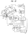
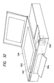
- Fig. 32 shows a perspective view for illustrating a general configuration of a copying apparatus to which the present invention is applied.
- a document sheet is mounted on a document sheet mount glass 1202 and it is illuminated by an illumination lamp (not shown) through bottom plane of the glass and a reflected light is sensed by a photo-electric conversion sensor 1201 to convert it to an electrical signal.
- the photo-electric sensor 1201 has the same resolution as that of the recording head (400 dots/inch) and can read 512 pixels corresponding to the width of one band of the image at a time. (Accordingly, the read width is 512-pixel width.)
- the reading of the image is the repetition of reading one band along the main scan direction, moving the sensor 1201 by the distance equal to the read width in the sub-scan direction and resuming the reading.
- the read image data is processed by the image processing unit to be described later and converted to the record signal and sent to the recording head 1203.
- the recording method of the recording head 1203 and the feed method of the recording sheet 1204 are similar to those for the previous embodiment.
- the recording sheet 1204 is fed by a sheet feed mechanism from a recording sheet cassette at the bottom of the copying apparatus 1200.
- Figs. 33A and 33B show block diagrams for explaining the configuration of the controller and the image processing unit of the copying apparatus of the present embodiment.
- a photo-electric conversion sensor for full color (full color sensor) 1201 comprises a CCD (charge coupled device) sensor, and red, green and blue filters are attached to three such sensors to form the sensors for red, green and blue. Accordingly, they are constructed to produce three signals for red, green and blue colors, respectively, namely, three output signals represent one pixel.
- CCD charge coupled device
- the image signal is photo-electrically converted by the full color sensor 1201 and converted to a digital signal by an A/D conversion circuit 1302.
- the digital image signal is sequentially sent to a shading correction circuit 1303 for correcting the irregularity of a sensitivity, a brilliance-density conversion circuit for converting the brilliance to the density, a black extraction circuit 1305 for generating a black signal from the color signal and a read area control circuit 1306 for controlling the read area of the document sheet.
- a coordinate may be specified by an editor (not shown) and the document area may be recognized by detecting the document sheet.
- the read area control circuit 1306 may control the read area and the image signal may be transferred downward or stopped.
- the area-controlled image signal is digitally magnified or reduced by a variable magnification circuit 1307 in accordance with a magnification factor specified by a console unit (not shown).
- a head shading circuit 1308 records various density patterns generated by the image processing circuit on a recording sheet.
- the recording sheet is then mounted on the document sheet table and the density patterns recorded on the recording sheet are read by the sensor 1201.
- the node is converted such that an area of the read pattern having a low density is given a high density and an area having a high density is given a low density to correct the image data so that the record for a given density appears in a uniform density.
- the recorded pattern is read by using the multi-scan to prepare the correction data.
- the density compensation which complies with the characteristic of the printer is conducted by the density correction circuit 1309.
- the density-corrected image signal is binarized (based on an error diffusion method) by a binarization circuit 1310 and the results are stored in the image memories 1311 to 1312 of the respective colors.
- the recorded image signal is sequentially read in synchronism by the print control circuit 1315.
- the record pattern is controlled by the print control circuit 1315 and whether the recording is made in the zig-zag pattern shown in Fig. 31 or not is determined.
- the print control circuit 1315 drives the heads 1203-1 to 1203-4 for the respective colors based on the received image signal and controls the discharge and the non-discharge of the ink to record the image (the reproduced image of the read original image) on the recording sheet.
- the control of the flow of the image signal and the control of the units of the copying apparatus are conducted by a microprocessor (CPU 1320) based on a control program stored in a memory (ROM 1327, RAM 1328) and the drive of a motor 1324, a sensor 1326 and other output means 1325 is controlled through input/output circuits 1321 and 1323.
- a microprocessor CPU 1320
- ROM 1327, RAM 1328 a control program stored in a memory
- a sensor 1326 and other output means 1325 is controlled through input/output circuits 1321 and 1323.
- the settings for operating the copying apparatus selection of recording sheet, magnification, continuous copy and etc.
- the start of the copy operation may be manually set on a console panel of a console unit 1322 connected to the CPU 1320.
- Fig. 34 shows a flow chart of a series of operations from the start of copy operation to the output of the reproduced image.
- An operator sets a document sheet on the document sheet table and instructs the start of copy operation through the console panel.
- the operations of the respective units of the copying apparatus are started (S401), a lamp to illuminate the document sheet is turned on, a correction sheet is read and shading correction data for the sensor is read (S402).
- the recording sheet is fed from the recording sheet cassette and it is fed to the recording unit (S403).
- the record pattern data is written into the record control circuit 1315 (S404). The band determination is required because the nozzles to be used are different depending on whether it is the first band or the last band in the multi-scan.
- the memory start positions of the memories 1311 to 1314 are calculated (S405). This is needed because in conducting the multi-scan to record a plurality of lines located at the end of the band by a plurality of nozzles, when the upper end portion (facing the first nozzle) of the band is to be recorded in the zig-zag pattern, the portion corresponding to the three lower nozzles of the image data read and recorded in the previous run is also to be recorded in the zig-zag pattern.
- the image signal read by the sensor and binarized is outputted in the following manner for the synchronous reading. First, several pixels of image is recorded in the memory and the reading is started while new pixels are written into the memory and read.
- the sensor and the head are returned to the start position for reading and recording, respectively (S408).
- the distance equal to the record width less the width corresponding to the end (the multi-scan distance) in the sub-scan direction of the recording sheet is calculated as the recording sheet feed distance.
- the start position of the next reading is calculated (S409).
- the four colors, cyan, magenta, yellow and black are multi-scanned by the same record pattern using one recording control circuit although a plurality of recording control circuits, one for each color, may be provided and the multi-scan may be conducted with different record patterns.
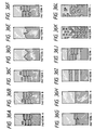
- Fig. 35 shows an example of the multi-scan with different record patterns.
- the cyan record pattern and the magenta record pattern are different from each other. Namely, the numbers of nozzles for the multi-scan are different and the grid intervals of the zig-zag pattern are different.
- Figs. 36A to 36L illustrate various multi-scan patterns. Rectangular pixels forming each pattern correspond to the nozzles, and the pixels represented by mesh correspond to the pattern recorded in the first scan and the pixels represented by hatching correspond to the pattern recorded in the second scan. The sizes and the number of times of repetition are not limited to those shown in Fig. 35 or Figs. 36A to 36L.
- each pattern is recorded in the following manner.
- pixels are recorded alternately in a short dot line pattern.
- a pattern B pixels are recorded with slight overlap of dots of the dotted line of the pattern A to make the separation of dots unclear.
- a boundary of a portion in which the entire area is recorded at a time without the multi-scan and a portion in which the multi-scan is conducted is recorded in a discrete pattern.
- the multi-scan is conducted in a triangle shape.
- a pattern E it is conducted in a sawtooth shape.
- a pattern F the manner of recording of the multi-scan portion of the pattern A is reversed.
- a pattern H the multi-scan pattern is not conducted.
- a pattern J the pattern I is modified.
- the amount of printing in the boundary area is gradually reduced or increased.
- the boundary area is blanked in wedge shape.
- the record patterns A to L may be changed for each color to be recorded.
- the pattern A may be used for cyan and the pattern F may be used for magenta.
- the number of lines for the multi-scan may be changed for each color to be recorded.
- the cyan recording may use the pattern C with the 9-line multi-scan
- the yellow recording may use the pattern H without the multi-scan
- the black recording may use the pattern G with the 3-line multi-scan.
- the pattern may not be changed but only the number of lines for the multi-scan may be changed.
- the number of lines is not limited to the specific number.
- the pattern for the multi-scan may be changed with the amount of record. For example, when the amount of record is large, the pattern A may be used and when the amount of record is small, the pattern G or H may be used. In the latter case, the recording speed is higher than that of the former case.
- the record pattern may be selected by taking the property of the ink into account. For example, when the ink which is readily affected by other inks is used, the record pattern of other color may be used depending on the count of the ink.
- whether the multi-scan is to be conducted or not may be determined by a ratio of the count to the total number of pixels. For example, when the count is lower than a predetermined count, the multi-scan may not be conducted.
- a switch for selecting the multi-scan may be provided on the console unit. For example, for a document sheet having many fine patterns and non-prominent irregularity, the multi-scan is not conducted. For a document sheet having many uniform images, the multi-scan may be conducted.
- the area to be multi-scanned is recorded in two scans although it is not restrictive but three or more scans may be used. Further, the area to be multi-scanned may be divided into the 2-scan area and the 3-scan area.
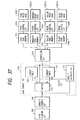
- Fig. 37 shows a diagram of a configuration of an image processing unit having an end correction circuit built therein.
- the image data having processed by the head shading circuit 1308 and the density correction circuit 1309 is applied to the end correction circuit 1700.
- the density of the image is matrix-calculated by the density calculation circuit 1703.
- the table circuits 1703 and 1704 including a plurality of conversion tables are selected. The conversion of the density of the image is conducted by the selected tables.
- the switch 1701 determined whether the recording is toward the boundary of bands or away from the boundary depending on the location of nozzle by which the image signal is recorded. Based on the decision, the table is switched. Namely, whether the table 1703 having the gradually descending density gradient is to be used or the table 1704 having the reverse density gradient is to be used is determined. For the image signal corresponding to zero nozzle at the boundary, it is not passed to the conversion table. In this case, the density correction is made for ten nozzles at the boundary of bands.
- the image signal from the end correction circuit is binarized by the binarization circuit 1310 and temporarily stored in the synchronization memories 1705 to 1708 for the respective colors.
- the synchronization memories correct the head distance and synchronize the signal.
- This memory is of smaller capacity than that shown in Figs. 33A and 33B because in Figs. 33A and 33B, the image signal not recorded by the record control circuit is read from the memory and recorded in the next band recording and hence one extra band need be stored while in Fig. 37, the multi-scan is conducted at the end and the record of the first band and the record of the second band use different correction tables, and hence the multi-scan area need be read again and passed through the correction table.
- the control such as the movement of the sensor so that the multi-scan area is read again by the image read control.
- select the start location of the nozzle for the end correction and the correction table may be changed depending on the multi-scan pattern. It may be changed in pair with the multi-scan pattern depending on the type of the recording sheet.
- the use of only the end correction, the use of only the multi-scan and the use of both the end correction and the multi-scan may be selected. In this case, whether the multi-scan is conducted simultaneously or not, the switch for selecting the start location of nozzle for the end correction and the correction table may be changed.
Landscapes
- Engineering & Computer Science (AREA)
- Physics & Mathematics (AREA)
- Mathematical Physics (AREA)
- General Engineering & Computer Science (AREA)
- General Physics & Mathematics (AREA)
- Theoretical Computer Science (AREA)
- Quality & Reliability (AREA)
- Ink Jet (AREA)
Applications Claiming Priority (9)
| Application Number | Priority Date | Filing Date | Title |
|---|---|---|---|
| JP4553695A JPH08238762A (ja) | 1995-03-06 | 1995-03-06 | インクジェット記録装置 |
| JP45536/95 | 1995-03-06 | ||
| JP4553695 | 1995-03-06 | ||
| JP7048567A JPH08244253A (ja) | 1995-03-08 | 1995-03-08 | 記録装置および方法と、情報処理システム |
| JP4856795 | 1995-03-08 | ||
| JP48567/95 | 1995-03-08 | ||
| JP10853195A JP3382410B2 (ja) | 1995-05-02 | 1995-05-02 | 記録装置及び方法 |
| JP108531/95 | 1995-05-02 | ||
| JP10853195 | 1995-05-02 |
Publications (4)
| Publication Number | Publication Date |
|---|---|
| EP0730973A2 true EP0730973A2 (fr) | 1996-09-11 |
| EP0730973A3 EP0730973A3 (fr) | 1998-01-07 |
| EP0730973B1 EP0730973B1 (fr) | 2004-05-26 |
| EP0730973B2 EP0730973B2 (fr) | 2010-11-17 |
Family
ID=27292267
Family Applications (1)
| Application Number | Title | Priority Date | Filing Date |
|---|---|---|---|
| EP96301499A Expired - Lifetime EP0730973B2 (fr) | 1995-03-06 | 1996-03-05 | Appareil et méthode d'enregistrement |
Country Status (3)
| Country | Link |
|---|---|
| US (1) | US5847721A (fr) |
| EP (1) | EP0730973B2 (fr) |
| DE (1) | DE69632555T3 (fr) |
Cited By (10)
| Publication number | Priority date | Publication date | Assignee | Title |
|---|---|---|---|---|
| EP0842781A2 (fr) * | 1996-10-30 | 1998-05-20 | Canon Kabushiki Kaisha | Appareil et méthode d'impression à jet d'encre pour la réduction de l'inégalité de densité dans une image imprimée occasionnée par la déviation de la position d'application d'encre |
| EP0876920A2 (fr) * | 1997-05-07 | 1998-11-11 | Seiko Epson Corporation | Impression par points avec double balayage partiel de lignes de trames |
| EP0941859A1 (fr) * | 1998-03-12 | 1999-09-15 | Brother Kogyo Kabushiki Kaisha | Imprimante, système d'impression et moyen de stockage |
| US6099105A (en) * | 1996-07-18 | 2000-08-08 | Seiko Epson Corporation | Printing system and method for recording images using multivaluing techniques |
| EP1029686A1 (fr) * | 1999-02-17 | 2000-08-23 | Hewlett-Packard Company | Dispositif et méthode d'impression |
| EP1029688A1 (fr) * | 1999-02-17 | 2000-08-23 | Hewlett-Packard Company | Dispositif et procédé d'impression |
| EP0945825A3 (fr) * | 1998-03-26 | 2000-10-04 | Canon Kabushiki Kaisha | Dispositif d'impression |
| EP1073007A2 (fr) * | 1999-07-30 | 2001-01-31 | Alps Electric Co., Ltd. | Procédé d'enregistrement d'images |
| EP1085458A1 (fr) * | 1999-09-20 | 2001-03-21 | Hewlett-Packard Company | Motif de masque hybride pour imprimante à jet d'encre à multiple gouttes |
| WO2008040712A1 (fr) * | 2006-10-02 | 2008-04-10 | Mutoh Europe Nv | Procédé de lissage d'impression |
Families Citing this family (37)
| Publication number | Priority date | Publication date | Assignee | Title |
|---|---|---|---|---|
| JP3359253B2 (ja) * | 1997-01-31 | 2002-12-24 | キヤノン株式会社 | 記録装置および記録方法 |
| JP4530438B2 (ja) * | 1998-08-11 | 2010-08-25 | オリンパス株式会社 | 画像形成装置 |
| DE60045809D1 (de) * | 1999-07-19 | 2011-05-19 | Canon Kk | Druckvorrichtung und Druckverfahren |
| US6960037B2 (en) * | 2002-09-20 | 2005-11-01 | Fuji Photo Film Co., Ltd. | Printer and feeding control method |
| US6702425B1 (en) * | 2002-09-23 | 2004-03-09 | Eastman Kodak Company | Coalescence-free inkjet printing by controlling drop spreading on/in a receiver |
| JP4307092B2 (ja) * | 2003-01-31 | 2009-08-05 | キヤノン株式会社 | インクジェット記録装置及びインクジェット記録装置の制御方法 |
| JP2004358965A (ja) * | 2003-05-14 | 2004-12-24 | Seiko Epson Corp | 印刷装置及び調整方法 |
| JP2005144893A (ja) * | 2003-11-17 | 2005-06-09 | Ricoh Co Ltd | インクジェット記録装置および画像形成装置 |
| JP2005169754A (ja) * | 2003-12-09 | 2005-06-30 | Canon Inc | インクジェット記録装置及びインクジェット記録方法 |
| JP2005178042A (ja) * | 2003-12-16 | 2005-07-07 | Seiko Epson Corp | 印刷装置、コンピュータプログラム、印刷システム、及び、インク滴の吐出方法 |
| US7847979B2 (en) * | 2006-07-07 | 2010-12-07 | Eastman Kodak Company | Printer having differential filtering smear correction |
| JP4389953B2 (ja) * | 2007-03-22 | 2009-12-24 | セイコーエプソン株式会社 | パターン形成方法 |
| JP5584490B2 (ja) * | 2010-02-18 | 2014-09-03 | キヤノン株式会社 | 画像処理装置、画像処理方法およびプログラム |
| US8403442B2 (en) | 2010-04-23 | 2013-03-26 | Seiko Epson Corporation | Printing device and printing method |
| CN103842914B (zh) | 2011-09-27 | 2016-01-20 | 伊斯曼柯达公司 | 利用大颗粒的喷墨印刷 |
| US8807730B2 (en) | 2011-12-22 | 2014-08-19 | Eastman Kodak Company | Inkjet printing on semi-porous or non-absorbent surfaces |
| US8764180B2 (en) | 2011-12-22 | 2014-07-01 | Eastman Kodak Company | Inkjet printing method with enhanced deinkability |
| US8857937B2 (en) | 2011-12-22 | 2014-10-14 | Eastman Kodak Company | Method for printing on locally distorable mediums |
| US8814292B2 (en) | 2011-12-22 | 2014-08-26 | Eastman Kodak Company | Inkjet printer for semi-porous or non-absorbent surfaces |
| US8770701B2 (en) | 2011-12-22 | 2014-07-08 | Eastman Kodak Company | Inkjet printer with enhanced deinkability |
| US8864255B2 (en) | 2011-12-22 | 2014-10-21 | Eastman Kodak Company | Method for printing with adaptive distortion control |
| US8761652B2 (en) | 2011-12-22 | 2014-06-24 | Eastman Kodak Company | Printer with liquid enhanced fixing system |
| US8717395B2 (en) | 2012-07-12 | 2014-05-06 | Eastman Kodak Company | Large-particle inkjet receiver-charging intermediate member |
| US8791971B2 (en) | 2012-07-12 | 2014-07-29 | Eastman Kodak Company | Large-particle inkjet dual-sign development printing |
| JP6035291B2 (ja) * | 2014-07-31 | 2016-11-30 | 京セラドキュメントソリューションズ株式会社 | ステッピングモーター駆動装置及び画像形成装置 |
| JP6443115B2 (ja) | 2015-02-20 | 2018-12-26 | ブラザー工業株式会社 | 制御装置およびコンピュータプログラム |
| JP6394432B2 (ja) | 2015-02-20 | 2018-09-26 | ブラザー工業株式会社 | 印刷制御装置、および、コンピュータプログラム |
| JP6443116B2 (ja) | 2015-02-20 | 2018-12-26 | ブラザー工業株式会社 | 印刷制御装置 |
| JP6413857B2 (ja) | 2015-03-13 | 2018-10-31 | セイコーエプソン株式会社 | ドット記録装置、ドット記録方法、そのためのコンピュータープログラム、及び、記録媒体の製造方法 |
| JP6500520B2 (ja) * | 2015-03-13 | 2019-04-17 | セイコーエプソン株式会社 | ドット記録装置、ドット記録方法、そのためのコンピュータープログラム、及び、記録媒体の製造方法 |
| JP6870626B2 (ja) | 2018-01-31 | 2021-05-12 | ブラザー工業株式会社 | 画像記録装置 |
| CN110116551B (zh) * | 2018-02-06 | 2021-04-30 | 株式会社理光 | 打印均匀度校正方法、装置、介质、设备、系统及打印机 |
| JP6888576B2 (ja) | 2018-03-26 | 2021-06-16 | ブラザー工業株式会社 | 画像記録装置 |
| JP6978728B2 (ja) | 2018-03-30 | 2021-12-08 | ブラザー工業株式会社 | 制御装置、および、コンピュータプログラム |
| JP7193773B2 (ja) | 2018-03-30 | 2022-12-21 | ブラザー工業株式会社 | 制御装置、および、コンピュータプログラム |
| JP2021053986A (ja) | 2019-09-30 | 2021-04-08 | ブラザー工業株式会社 | 液滴吐出装置 |
| JP7436956B2 (ja) * | 2020-01-28 | 2024-02-22 | ブラザー工業株式会社 | 印刷装置、および、コンピュータプログラム |
Citations (14)
| Publication number | Priority date | Publication date | Assignee | Title |
|---|---|---|---|---|
| US4272771A (en) † | 1978-09-25 | 1981-06-09 | Ricoh Co., Ltd. | Ink jet printer with multiple nozzle print head and interlacing or dither means |
| JPS60107975A (ja) † | 1983-11-16 | 1985-06-13 | Ricoh Co Ltd | インクジエツト記録装置 |
| US4748453A (en) † | 1987-07-21 | 1988-05-31 | Xerox Corporation | Spot deposition for liquid ink printing |
| EP0347257A2 (fr) † | 1988-06-17 | 1989-12-20 | Canon Kabushiki Kaisha | Appareil d'enregistrement d'images |
| US4967203A (en) † | 1989-09-29 | 1990-10-30 | Hewlett-Packard Company | Interlace printing process |
| US4999646A (en) † | 1989-11-29 | 1991-03-12 | Hewlett-Packard Company | Method for enhancing the uniformity and consistency of dot formation produced by color ink jet printing |
| WO1992017340A1 (fr) * | 1991-03-28 | 1992-10-15 | Mannesmann Ag | Procede d'enregistrement d'informations |
| EP0522980A2 (fr) * | 1991-06-17 | 1993-01-13 | Eastman Kodak Company | Méthode et appareil pour imprimer thermiquement de grandes images avec de petites surfaces d'encrage |
| EP0526205A2 (fr) † | 1991-07-30 | 1993-02-03 | Canon Kabushiki Kaisha | Appareil et méthode d'enregistrement par jet d'encre |
| DE4127560A1 (de) † | 1991-08-19 | 1993-02-25 | Mannesmann Ag | Aufzeichnungsverfahren |
| EP0546853A1 (fr) * | 1991-12-13 | 1993-06-16 | Canon Kabushiki Kaisha | Procédé et appareil d'enregistrement à jet d'encre |
| DE4141736A1 (de) * | 1991-03-28 | 1993-06-17 | Mannesmann Ag | Verfahren zum aufzeichnen von informationen |
| EP0578434A2 (fr) * | 1992-07-06 | 1994-01-12 | Canon Kabushiki Kaisha | Procédé d'enregistrement à jet d'encres |
| EP0597714A1 (fr) * | 1992-11-12 | 1994-05-18 | Canon Kabushiki Kaisha | Procédé d'enregistrement à jet d'encre |
Family Cites Families (4)
| Publication number | Priority date | Publication date | Assignee | Title |
|---|---|---|---|---|
| JPH0635192B2 (ja) * | 1984-11-19 | 1994-05-11 | キヤノン株式会社 | 記録装置 |
| US5583550A (en) * | 1989-09-29 | 1996-12-10 | Hewlett-Packard Company | Ink drop placement for improved imaging |
| US5432617A (en) * | 1990-09-27 | 1995-07-11 | Canon Kabushiki Kaisha | Method and apparatus using a control signal to designate a print area on a recording medium |
| GB2251581B (en) * | 1990-11-09 | 1995-01-11 | Dataproducts Corp | Interlaced ink jet printer |
-
1996
- 1996-03-05 EP EP96301499A patent/EP0730973B2/fr not_active Expired - Lifetime
- 1996-03-05 US US08/610,879 patent/US5847721A/en not_active Expired - Lifetime
- 1996-03-05 DE DE69632555T patent/DE69632555T3/de not_active Expired - Lifetime
Patent Citations (15)
| Publication number | Priority date | Publication date | Assignee | Title |
|---|---|---|---|---|
| US4272771A (en) † | 1978-09-25 | 1981-06-09 | Ricoh Co., Ltd. | Ink jet printer with multiple nozzle print head and interlacing or dither means |
| JPS60107975A (ja) † | 1983-11-16 | 1985-06-13 | Ricoh Co Ltd | インクジエツト記録装置 |
| US4748453A (en) † | 1987-07-21 | 1988-05-31 | Xerox Corporation | Spot deposition for liquid ink printing |
| EP0347257A2 (fr) † | 1988-06-17 | 1989-12-20 | Canon Kabushiki Kaisha | Appareil d'enregistrement d'images |
| EP0633139A1 (fr) * | 1989-09-29 | 1995-01-11 | Hewlett-Packard Company | Procédé d'impression entrelacée |
| US4967203A (en) † | 1989-09-29 | 1990-10-30 | Hewlett-Packard Company | Interlace printing process |
| US4999646A (en) † | 1989-11-29 | 1991-03-12 | Hewlett-Packard Company | Method for enhancing the uniformity and consistency of dot formation produced by color ink jet printing |
| WO1992017340A1 (fr) * | 1991-03-28 | 1992-10-15 | Mannesmann Ag | Procede d'enregistrement d'informations |
| DE4141736A1 (de) * | 1991-03-28 | 1993-06-17 | Mannesmann Ag | Verfahren zum aufzeichnen von informationen |
| EP0522980A2 (fr) * | 1991-06-17 | 1993-01-13 | Eastman Kodak Company | Méthode et appareil pour imprimer thermiquement de grandes images avec de petites surfaces d'encrage |
| EP0526205A2 (fr) † | 1991-07-30 | 1993-02-03 | Canon Kabushiki Kaisha | Appareil et méthode d'enregistrement par jet d'encre |
| DE4127560A1 (de) † | 1991-08-19 | 1993-02-25 | Mannesmann Ag | Aufzeichnungsverfahren |
| EP0546853A1 (fr) * | 1991-12-13 | 1993-06-16 | Canon Kabushiki Kaisha | Procédé et appareil d'enregistrement à jet d'encre |
| EP0578434A2 (fr) * | 1992-07-06 | 1994-01-12 | Canon Kabushiki Kaisha | Procédé d'enregistrement à jet d'encres |
| EP0597714A1 (fr) * | 1992-11-12 | 1994-05-18 | Canon Kabushiki Kaisha | Procédé d'enregistrement à jet d'encre |
Cited By (19)
| Publication number | Priority date | Publication date | Assignee | Title |
|---|---|---|---|---|
| US6099105A (en) * | 1996-07-18 | 2000-08-08 | Seiko Epson Corporation | Printing system and method for recording images using multivaluing techniques |
| EP0842781A3 (fr) * | 1996-10-30 | 1999-03-10 | Canon Kabushiki Kaisha | Appareil et méthode d'impression à jet d'encre pour la réduction de l'inégalité de densité dans une image imprimée occasionnée par la déviation de la position d'application d'encre |
| US6007181A (en) * | 1996-10-30 | 1999-12-28 | Canon Kabushiki Kaisha | Ink-jet printing apparatus and ink-jet printing method for reducing density unevenness in a printed image due to deviation of ink application position |
| EP0842781A2 (fr) * | 1996-10-30 | 1998-05-20 | Canon Kabushiki Kaisha | Appareil et méthode d'impression à jet d'encre pour la réduction de l'inégalité de densité dans une image imprimée occasionnée par la déviation de la position d'application d'encre |
| US6190001B1 (en) | 1997-05-07 | 2001-02-20 | Seiko Epson Corporation | Dot printing with partial double scanning of raster lines |
| EP0876920A2 (fr) * | 1997-05-07 | 1998-11-11 | Seiko Epson Corporation | Impression par points avec double balayage partiel de lignes de trames |
| EP0876920A3 (fr) * | 1997-05-07 | 1999-12-29 | Seiko Epson Corporation | Impression par points avec double balayage partiel de lignes de trames |
| EP0941859A1 (fr) * | 1998-03-12 | 1999-09-15 | Brother Kogyo Kabushiki Kaisha | Imprimante, système d'impression et moyen de stockage |
| US6603564B1 (en) | 1998-03-12 | 2003-08-05 | Brother Kogyo Kabushiki Kaisha | Printing device, printing system, and storage medium |
| EP0945825A3 (fr) * | 1998-03-26 | 2000-10-04 | Canon Kabushiki Kaisha | Dispositif d'impression |
| US6478394B1 (en) | 1998-03-26 | 2002-11-12 | Canon Kabushiki Kaisha | Printing apparatus |
| EP1029688A1 (fr) * | 1999-02-17 | 2000-08-23 | Hewlett-Packard Company | Dispositif et procédé d'impression |
| US6375307B1 (en) | 1999-02-17 | 2002-04-23 | Hewlett-Packard Company | Printing apparatus and method |
| EP1029686A1 (fr) * | 1999-02-17 | 2000-08-23 | Hewlett-Packard Company | Dispositif et méthode d'impression |
| EP1073007A2 (fr) * | 1999-07-30 | 2001-01-31 | Alps Electric Co., Ltd. | Procédé d'enregistrement d'images |
| EP1073007A3 (fr) * | 1999-07-30 | 2004-01-07 | Alps Electric Co., Ltd. | Procédé d'enregistrement d'images |
| EP1085458A1 (fr) * | 1999-09-20 | 2001-03-21 | Hewlett-Packard Company | Motif de masque hybride pour imprimante à jet d'encre à multiple gouttes |
| EP1310905A1 (fr) * | 1999-09-20 | 2003-05-14 | Hewlett-Packard Company | Motif de masque hybride pour imprimante à jet d'encre à multiple gouttes |
| WO2008040712A1 (fr) * | 2006-10-02 | 2008-04-10 | Mutoh Europe Nv | Procédé de lissage d'impression |
Also Published As
| Publication number | Publication date |
|---|---|
| US5847721A (en) | 1998-12-08 |
| DE69632555T3 (de) | 2011-05-12 |
| EP0730973B2 (fr) | 2010-11-17 |
| EP0730973B1 (fr) | 2004-05-26 |
| DE69632555T2 (de) | 2005-06-02 |
| DE69632555D1 (de) | 2004-07-01 |
| EP0730973A3 (fr) | 1998-01-07 |
Similar Documents
| Publication | Publication Date | Title |
|---|---|---|
| US5847721A (en) | Recording apparatus and method | |
| US5604520A (en) | Ink jet recording method using different mask patterns | |
| EP0730246B1 (fr) | Méthode de transition entre modes d'impression à jet d'encre | |
| EP0824244B1 (fr) | Code des couleurs bi-dimensionnel, méthode de préparation et de restauration du code et appareil correspondant | |
| JPH08244253A (ja) | 記録装置および方法と、情報処理システム | |
| US6254217B1 (en) | Apparatus and method for hue shift compensation in a bidirectional printer | |
| EP0597714A1 (fr) | Procédé d'enregistrement à jet d'encre | |
| EP0564252A2 (fr) | Procédé et appareil d'enregistrement à jets d'encre | |
| US5742300A (en) | Resolution enhancement and thinning method for printing pixel images | |
| EP1029693B1 (fr) | Impression par passages multiples | |
| EP1288002B1 (fr) | Procédé et appareil pour optimiser des volumes de gouttelettes séparés pour imprimantes multipoints à jet d'encre | |
| US6069709A (en) | Bi-directional printing with overlap using both breaks and transition regions | |
| US5610639A (en) | Image forming apparatus with a correction recording condition feature and related method | |
| EP0660586A2 (fr) | Procédé pour la commande de gradation et amélioration de la qualité de l'image dans une imprimante thermique | |
| JP2748321B2 (ja) | 画像形成装置 | |
| US6318830B1 (en) | Image printing method, and apparatus thereof | |
| EP0720918B1 (fr) | Méthode de suppression de pixels insensible aux bords pour une image d'impression à haute résolution | |
| US5596352A (en) | Printing apparatus and method for printing color boundary regions having reduced color bleed | |
| JP3323603B2 (ja) | インクジェット記録方法 | |
| EP0614307A1 (fr) | Procédé et appareil pour l'enregistrement d'images | |
| JP2793223B2 (ja) | 画像形成装置 | |
| JPH0820125A (ja) | サーマルプリンタにおける画質改善方法 | |
| US5844590A (en) | Image printing method and apparatus for printing an image based on stored and input image data, including elective printing in an overlapped data area | |
| JP3382410B2 (ja) | 記録装置及び方法 | |
| JPS63309457A (ja) | 画像処理方法 |
Legal Events
| Date | Code | Title | Description |
|---|---|---|---|
| PUAI | Public reference made under article 153(3) epc to a published international application that has entered the european phase |
Free format text: ORIGINAL CODE: 0009012 |
|
| AK | Designated contracting states |
Kind code of ref document: A2 Designated state(s): DE FR GB IT |
|
| PUAL | Search report despatched |
Free format text: ORIGINAL CODE: 0009013 |
|
| PUAF | Information related to the publication of a search report (a3 document) modified or deleted |
Free format text: ORIGINAL CODE: 0009199SEPU |
|
| AK | Designated contracting states |
Kind code of ref document: A3 Designated state(s): DE FR GB IT |
|
| D17D | Deferred search report published (deleted) | ||
| PUAL | Search report despatched |
Free format text: ORIGINAL CODE: 0009013 |
|
| AK | Designated contracting states |
Kind code of ref document: A3 Designated state(s): DE FR GB IT |
|
| 17P | Request for examination filed |
Effective date: 19980520 |
|
| 17Q | First examination report despatched |
Effective date: 20000913 |
|
| GRAP | Despatch of communication of intention to grant a patent |
Free format text: ORIGINAL CODE: EPIDOSNIGR1 |
|
| GRAS | Grant fee paid |
Free format text: ORIGINAL CODE: EPIDOSNIGR3 |
|
| GRAA | (expected) grant |
Free format text: ORIGINAL CODE: 0009210 |
|
| AK | Designated contracting states |
Kind code of ref document: B1 Designated state(s): DE FR GB IT |
|
| PG25 | Lapsed in a contracting state [announced via postgrant information from national office to epo] |
Ref country code: IT Free format text: LAPSE BECAUSE OF FAILURE TO SUBMIT A TRANSLATION OF THE DESCRIPTION OR TO PAY THE FEE WITHIN THE PRE;WARNING: LAPSES OF ITALIAN PATENTS WITH EFFECTIVE DATE BEFORE 2007 MAY HAVE OCCURRED AT ANY TIME BEFORE 2007. THE CORRECT EFFECTIVE DATE MAY BE DIFFERENT FROM THE ONE RECORDED.SCRIBED TIME-LIMIT Effective date: 20040526 Ref country code: FR Free format text: LAPSE BECAUSE OF NON-PAYMENT OF DUE FEES Effective date: 20040526 |
|
| REG | Reference to a national code |
Ref country code: GB Ref legal event code: FG4D |
|
| REF | Corresponds to: |
Ref document number: 69632555 Country of ref document: DE Date of ref document: 20040701 Kind code of ref document: P |
|
| PLAQ | Examination of admissibility of opposition: information related to despatch of communication + time limit deleted |
Free format text: ORIGINAL CODE: EPIDOSDOPE2 |
|
| PLAR | Examination of admissibility of opposition: information related to receipt of reply deleted |
Free format text: ORIGINAL CODE: EPIDOSDOPE4 |
|
| PLBQ | Unpublished change to opponent data |
Free format text: ORIGINAL CODE: EPIDOS OPPO |
|
| PLBI | Opposition filed |
Free format text: ORIGINAL CODE: 0009260 |
|
| 26 | Opposition filed |
Opponent name: OCE-TECHNOLOGIES B.V. Effective date: 20050218 |
|
| PLAQ | Examination of admissibility of opposition: information related to despatch of communication + time limit deleted |
Free format text: ORIGINAL CODE: EPIDOSDOPE2 |
|
| PLAR | Examination of admissibility of opposition: information related to receipt of reply deleted |
Free format text: ORIGINAL CODE: EPIDOSDOPE4 |
|
| PLAX | Notice of opposition and request to file observation + time limit sent |
Free format text: ORIGINAL CODE: EPIDOSNOBS2 |
|
| PLBQ | Unpublished change to opponent data |
Free format text: ORIGINAL CODE: EPIDOS OPPO |
|
| PLAB | Opposition data, opponent's data or that of the opponent's representative modified |
Free format text: ORIGINAL CODE: 0009299OPPO |
|
| EN | Fr: translation not filed | ||
| R26 | Opposition filed (corrected) |
Opponent name: OCE-TECHNOLOGIES B.V. Effective date: 20050218 |
|
| PLAF | Information modified related to communication of a notice of opposition and request to file observations + time limit |
Free format text: ORIGINAL CODE: EPIDOSCOBS2 |
|
| PLBB | Reply of patent proprietor to notice(s) of opposition received |
Free format text: ORIGINAL CODE: EPIDOSNOBS3 |
|
| RDAF | Communication despatched that patent is revoked |
Free format text: ORIGINAL CODE: EPIDOSNREV1 |
|
| APBP | Date of receipt of notice of appeal recorded |
Free format text: ORIGINAL CODE: EPIDOSNNOA2O |
|
| APAH | Appeal reference modified |
Free format text: ORIGINAL CODE: EPIDOSCREFNO |
|
| APBQ | Date of receipt of statement of grounds of appeal recorded |
Free format text: ORIGINAL CODE: EPIDOSNNOA3O |
|
| APBU | Appeal procedure closed |
Free format text: ORIGINAL CODE: EPIDOSNNOA9O |
|
| PUAH | Patent maintained in amended form |
Free format text: ORIGINAL CODE: 0009272 |
|
| STAA | Information on the status of an ep patent application or granted ep patent |
Free format text: STATUS: PATENT MAINTAINED AS AMENDED |
|
| 27A | Patent maintained in amended form |
Effective date: 20101117 |
|
| AK | Designated contracting states |
Kind code of ref document: B2 Designated state(s): DE FR GB IT |
|
| PGFP | Annual fee paid to national office [announced via postgrant information from national office to epo] |
Ref country code: GB Payment date: 20150316 Year of fee payment: 20 |
|
| PGFP | Annual fee paid to national office [announced via postgrant information from national office to epo] |
Ref country code: DE Payment date: 20150331 Year of fee payment: 20 |
|
| REG | Reference to a national code |
Ref country code: DE Ref legal event code: R071 Ref document number: 69632555 Country of ref document: DE |
|
| REG | Reference to a national code |
Ref country code: GB Ref legal event code: PE20 Expiry date: 20160304 |
|
| PG25 | Lapsed in a contracting state [announced via postgrant information from national office to epo] |
Ref country code: GB Free format text: LAPSE BECAUSE OF EXPIRATION OF PROTECTION Effective date: 20160304 |