EP0712987B2 - Schloss, insbesondere Treibstangenschloss mit zweigeteilter Drückernuss - Google Patents
Schloss, insbesondere Treibstangenschloss mit zweigeteilter Drückernuss Download PDFInfo
- Publication number
- EP0712987B2 EP0712987B2 EP95114646A EP95114646A EP0712987B2 EP 0712987 B2 EP0712987 B2 EP 0712987B2 EP 95114646 A EP95114646 A EP 95114646A EP 95114646 A EP95114646 A EP 95114646A EP 0712987 B2 EP0712987 B2 EP 0712987B2
- Authority
- EP
- European Patent Office
- Prior art keywords
- follower
- lock according
- halves
- actuating
- lock
- Prior art date
- Legal status (The legal status is an assumption and is not a legal conclusion. Google has not performed a legal analysis and makes no representation as to the accuracy of the status listed.)
- Expired - Lifetime
Links
- 230000008878 coupling Effects 0.000 claims description 33
- 238000010168 coupling process Methods 0.000 claims description 33
- 238000005859 coupling reaction Methods 0.000 claims description 33
- 230000007935 neutral effect Effects 0.000 claims description 12
- 230000000903 blocking effect Effects 0.000 claims description 8
- 230000015572 biosynthetic process Effects 0.000 claims 1
- 238000006073 displacement reaction Methods 0.000 description 3
- 230000006835 compression Effects 0.000 description 2
- 238000007906 compression Methods 0.000 description 2
- 238000011161 development Methods 0.000 description 2
- 230000018109 developmental process Effects 0.000 description 2
- 230000007717 exclusion Effects 0.000 description 2
- DCRGHMJXEBSRQG-UHFFFAOYSA-N 1-[1-(cyclooctylmethyl)-5-(hydroxymethyl)-3,6-dihydro-2H-pyridin-4-yl]-3-ethyl-2-benzimidazolone Chemical compound O=C1N(CC)C2=CC=CC=C2N1C(CC1)=C(CO)CN1CC1CCCCCCC1 DCRGHMJXEBSRQG-UHFFFAOYSA-N 0.000 description 1
- 230000000881 depressing effect Effects 0.000 description 1
- 230000000994 depressogenic effect Effects 0.000 description 1
- 230000003993 interaction Effects 0.000 description 1
- 230000002441 reversible effect Effects 0.000 description 1
- 238000000926 separation method Methods 0.000 description 1
- 230000004936 stimulating effect Effects 0.000 description 1
Images


Classifications
-
- E—FIXED CONSTRUCTIONS
- E05—LOCKS; KEYS; WINDOW OR DOOR FITTINGS; SAFES
- E05C—BOLTS OR FASTENING DEVICES FOR WINGS, SPECIALLY FOR DOORS OR WINDOWS
- E05C9/00—Arrangements of simultaneously actuated bolts or other securing devices at well-separated positions on the same wing
- E05C9/02—Arrangements of simultaneously actuated bolts or other securing devices at well-separated positions on the same wing with one sliding bar for fastening when moved in one direction and unfastening when moved in opposite direction; with two sliding bars moved in the same direction when fastening or unfastening
- E05C9/025—Arrangements of simultaneously actuated bolts or other securing devices at well-separated positions on the same wing with one sliding bar for fastening when moved in one direction and unfastening when moved in opposite direction; with two sliding bars moved in the same direction when fastening or unfastening with pins engaging slots
-
- E—FIXED CONSTRUCTIONS
- E05—LOCKS; KEYS; WINDOW OR DOOR FITTINGS; SAFES
- E05B—LOCKS; ACCESSORIES THEREFOR; HANDCUFFS
- E05B63/00—Locks or fastenings with special structural characteristics
- E05B63/04—Locks or fastenings with special structural characteristics for alternative use on the right-hand or left-hand side of wings
- E05B63/042—Locks or fastenings with special structural characteristics for alternative use on the right-hand or left-hand side of wings constructed symmetrically
-
- E—FIXED CONSTRUCTIONS
- E05—LOCKS; KEYS; WINDOW OR DOOR FITTINGS; SAFES
- E05C—BOLTS OR FASTENING DEVICES FOR WINGS, SPECIALLY FOR DOORS OR WINDOWS
- E05C9/00—Arrangements of simultaneously actuated bolts or other securing devices at well-separated positions on the same wing
- E05C9/02—Arrangements of simultaneously actuated bolts or other securing devices at well-separated positions on the same wing with one sliding bar for fastening when moved in one direction and unfastening when moved in opposite direction; with two sliding bars moved in the same direction when fastening or unfastening
- E05C9/026—Arrangements of simultaneously actuated bolts or other securing devices at well-separated positions on the same wing with one sliding bar for fastening when moved in one direction and unfastening when moved in opposite direction; with two sliding bars moved in the same direction when fastening or unfastening comprising key-operated locks, e.g. a lock cylinder to drive auxiliary deadbolts or latch bolts
-
- E—FIXED CONSTRUCTIONS
- E05—LOCKS; KEYS; WINDOW OR DOOR FITTINGS; SAFES
- E05B—LOCKS; ACCESSORIES THEREFOR; HANDCUFFS
- E05B15/00—Other details of locks; Parts for engagement by bolts of fastening devices
- E05B15/0033—Spindles for handles, e.g. square spindles
-
- E—FIXED CONSTRUCTIONS
- E05—LOCKS; KEYS; WINDOW OR DOOR FITTINGS; SAFES
- E05B—LOCKS; ACCESSORIES THEREFOR; HANDCUFFS
- E05B59/00—Locks with latches separate from the lock-bolts or with a plurality of latches or lock-bolts
-
- E—FIXED CONSTRUCTIONS
- E05—LOCKS; KEYS; WINDOW OR DOOR FITTINGS; SAFES
- E05B—LOCKS; ACCESSORIES THEREFOR; HANDCUFFS
- E05B63/00—Locks or fastenings with special structural characteristics
- E05B63/16—Locks or fastenings with special structural characteristics with the handles on opposite sides moving independently
Definitions
- the invention relates to a lock, in particular espagnolette lock according to Generic term of claim 1.
- EP 0 620 341 A1 and the associated DE 694 08 012 T2 describe one such espagnolette lock.
- the nut has two nut halves, the either with one from one or the other side of the nut a central arm can be coupled. This arm grips a ledge a trap to withdraw the trap.
- the espagnolette lock disclosed there has one consisting of two halves Trigger nut on.
- the halves are in the axial direction to each other, with each half a trigger pin assigned is.
- a push pin especially the inner one Trigger mandrel, can be activated by pressing the trigger Withdraw the trap. To do this, it points to the inner handle associated nut half an arm that with a Actuating projection of the trap interacts.
- the both pusher halves are the same as the two Turning the nut halves so that the actuation of the Inside handle or the outside handle the opposite other pusher or this pusher assigned nut half leaves unaffected.
- known lock is the trap only by pressing the inner half of the nut retractable.
- An actuation of the outer half of the nut has no trap retraction.
- Both nut halves can also be turned in the opposite direction. When the pushers are actuated in the opposite direction there is a relocation of an im Lock case arranged drive rod.
- the invention is therefore based on the object a generic lock useful further education.
- the configuration according to the invention is a lock, especially espagnolette lock given, with which a simple means Left / right changeover is possible.
- the mirror symmetry trained nut halves can either the one, the other or both of the nut halves coupled to the trap become.
- the coupling links are detachable and therefore relocatable even after the lock has been manufactured or reversible, so that the coupling between Trap and nut is adjustable.
- the trap is preferred assigned an actuating section on the tail side.
- This actuating section can be designed as a projection his. It is further preferred that the lock be a Change lever is assigned, which on this operating section acts. In a preferred further training the invention provides that the nut actuation is locked when the bolt is locked. It is also conceivable, instead of the nut relocability to lock the connecting rod connecting slide. For this can a protruding into the actuation path of the nut Locking element can be provided, which is a locking slide assigned.
- the gate valve can be together with the bolt exclusion in Deadbolt movement be shifted.
- the Gate valve preferably has two fork-shaped arranged Locking tines on, each locking tine with a locking projection of one of the two nut halves cooperates. Each nut preferably has an actuating arm on.
- the two operating arms should in the axial direction (pusher mandrel axis) from each other be spaced so that between the two arms there is a gap. In this space can at the turn of the nut the operating section of the trap tail protrude.
- the coupling member can either the trap tail or the nut arm be assigned.
- the coupling link is the nut arm assigned, it is preferably provided that it is in the Clearance space protrudes, so that when the nut rotates the coupling member the operating section of the trap tail acted upon and thereby pulls back the trap.
- the coupling piece is the trap tail assigned, it is preferably in the region of the actuating section arranged and protrudes in the axial direction in the path of movement of one or both nut arms.
- each half of the nut is sprung individually Held in the middle position.
- the sprung middle position can be maintained by a two-armed slide be, as in DE-OS 40 41 537 is described in detail. It is preferred that one such spring-loaded slide is provided twice, each slider separately on one of the two nut halves acts. Both nut halves have a radial one Edge recess in which a tooth a Swing lever protrudes. The opening of the radial recess is much larger than the effective thickness of the Tooth, so that there is nut clearance.
- Such one Access is also in OS 40 41 537 in Described in detail and serves to ensure that after a Espagnolette displacement either in the open or in the locking position the nut back to the neutral position is returned. Between the two edge areas, which the radial recess is assigned to a clearance is also provided, in which a portion of the pivot lever protrudes. Each in Two teeth protrude from this section of the swivel lever.
- a further development of the invention provides that the coupling member is not the operating arm is assigned to the two nut halves, but that Catch tail.
- the coupling member is preferably the actuating section of the trap tail assigned and displaceable in the transverse direction to the castle level.
- the displaceability of the coupling member can be done by a spindle drive, which is in the form a screw rotatably arranged in the trap tail is trained.
- the spindle drive can have a Screwdriver.
- the spindle is supported at both ends in the operating section, so that a narrow actuator in a space is displaceable in the transverse direction that it is in one extreme position by an operating arm one half of the nut can be loaded, but not from the other and in the other extreme position acted upon by the other half of the nut is, in which case the other half of the nut is released.
- the functioning of the lock corresponds essentially that of the castle according to the OS 40 41 537.
- the design is also shared there described.
- the lock according to the invention has one Lock case on which a lock floor 35 and has a lock cover 34. This is indicated on the front Unlocked a cuff with openings through which a latch head 8 a latch 1 and a bolt 29 step through. Along the cuff is in the lock case a connecting rod connecting slide 22 guided.
- a pivot lever 19 which has a first arm in which a slot 20 is provided; in the latter protrudes a pin 21.
- the pin 21 is with the Espagnolette connecting slide 22 connected.
- the pivot lever 19 has two axially opposite Pins or teeth 18 on, which by a portion 44 are separated.
- the two pins 18 protrude into a radial recess 17 of the two nut halves 5, 6 a.
- the radial recess 17 has such a circumferential angular width that each of the two nut halves 5, 6 held in the neutral position regardless of the position of the Swivel lever 19 between its two end positions (Fig. 1, Fig. 2).
- the neutral position of the two nut halves 5, 6 is in each case by a sprung slide 14, 36 maintained.
- the slide 14, 36 has two Slider arms 15, which with drivers 16 of the Nut work together.
- OS 40 41 537 In terms of interaction of slides 14, 36 with the drivers 16 of the both nut halves are referred to OS 40 41 537.
- a bolt 29 is provided in the lock housing, which by actuating a profile locking cylinder is lockable and lockable.
- the lock cylinder has a closing member 31, which with a tumbler 30 interacts. There is one on the bar Exchange lever stored, which of the Locking member 31 can be acted upon.
- the second arm of the Kirs 31 acts on an operating section 7 of the trap tail 2 so that when changing the trap 1 is withdrawn.
- the espagnolette lock has two in the axial direction the lever axis one behind the other Nut halves 5 and 6.
- the nut halves 5, 6 are symmetrical and each have an arm 10 on.
- the arms 10 are at least in the area of their free Ends spaced. Forms between the trap arms a space in which a stop 9 of the actuating section 7 of the case 1 protrudes.
- Everyone who both arms 10 has a bore into which one Coupling pin can be inserted.
- 6 is the coupling pin 11 in the right nut half 6 and in Fig. 7 the coupling pin 11 is inserted into the left nut half 5. Accordingly, the traps are withdrawn in accordance with 6 when the handle 4 is actuated and according to FIG. 7 when pressing the trigger 3.
- the two nut halves 5, 6 are not entrained in rotation, but rather can be rotated against each other without turning entrainment become.
- the two trigger mandrel sections 3.4 can be rotated against each other.
- the Stimulating the two axially aligned to each other Mandrel sections 3, 4 are spaced apart. They lie in a blind hole 23 with a rectangular cross section the respective nut half 5, 6 a.
- It is a coupling pin 38 is provided which consists of one of the protrudes both ends of the pusher dome 4 and in the opposite end face of the trigger mandrel section 3 protrudes. The pin is designed so round that the two pushers 3, 4 against each other can be twisted.
- the mirror-symmetrical Nut halves 5,6 slide with one of their end faces each other. Point opposite the end faces the nut halves 5, 6 on a cylindrical collar, which in a corresponding opening of Castle cover 34 or castle floor 35 is inserted. It is provided that in both arms 10 of the two nut halves 5, 6 a coupling pin 11 can be inserted.
- the coupling pin 11 extends up to the level of the parting line the two halves of the nut in the space. It sticks out especially in the space between the two free ends of the arms 10. In the plane of the parting line is a section 9 of the trap, which the releasable Coupling member 11 acted upon nut actuation.
- driver projections 16 On the opposite of the parting line
- the end face of the nut 5, 6 are driver projections 16 arranged, on each of which a prong 15, 37 one Slider 14 rests.
- the drivers 16 are approximately diametrical arranged opposite, so that depending on Direction of rotation of the slider nut along with a compression of the spring 32, 33 is shifted.
- the the two springs 32, 33 are in alignment with one another Lock case arranged and act on the Slider 14, 36 elastic.
- a gate valve 27 is arranged.
- the gate valve 27 has two parallel tines 45, 46, wherein each tine 45, 46 is provided with a spermase 25, which interacts with a locking projection 26 of the nut.
- the locking lug 25 undermines the locking projection 26 when the slide 27 in Bolt exclusion direction is shifted. This can the pusher 24 can no longer be depressed to to move the drive rod into the open position.
- the trap head 8 only needs 180 ° be rotated.
- a cylindrical trap tail 2 provided, which with a screw 39 in a trap end piece, which is from the operating section 7 is formed, is attached to the latter. Loosening the screw 39 enables turning the trap 8.
- the pin 11 from the Nut half 6 are pulled out and (as in Fig. 7 shown) are inserted into the nut half 5. Then the nut half 6 is uncoupled from the trap.
- the coupling member 47 is the trap tail, namely assigned to the actuating section 107.
- the actuating section 107 has one U-shaped recess in which a plate lies, which with an end portion 47 'of the latch arm 110 can be acted upon.
- the plate 47 has approximately a thickness that corresponds to half of the U-space.
- a Rotation of screw 48 does not cause displacement the screw opposite the operating section 107.
- the coupling member 47 has an internal thread into which the external thread of the screw 48 protrudes. The screw 48 thus acts as a threaded spindle.
- the Coupling member 47 transverse to the lock extension plane shift so that it is either from the actuating arm 110 the nut half 106 or the actuating arm 110 'of Nut half 105 can be applied.
- the each the other half of the nut is then released without the latch being actuated becomes.
- the Nut halves parallel to each other in such a way that the two Actuating arms 110, 110 'separated by a free space are. This enables a clean separation of movements by transverse displacement of the coupling member 47th
- the trap tail 102 of the trap 101 has one Pocket 49 in which an end portion of a Exchange lever 113 immersed.
- the trap tail 102 continues towards the rear into an operating section 107, which has the recess in which the coupling member 47 is displaceable transversely is.
- the two nut halves 105, 106 are in their neutral center position by a slide 114 held, which is acted upon by a compression spring 133 becomes.
- the slider 114 has two fork tines 15 on the corresponding driver 16 of the Soak in the nut halves.
Landscapes
- Engineering & Computer Science (AREA)
- Mechanical Engineering (AREA)
- Structural Engineering (AREA)
- Lock And Its Accessories (AREA)
- Arrangement Or Mounting Of Control Devices For Change-Speed Gearing (AREA)
- Pharmaceuticals Containing Other Organic And Inorganic Compounds (AREA)
- Press Drives And Press Lines (AREA)
- Automatic Assembly (AREA)
- Mechanical Control Devices (AREA)
- Preventing Unauthorised Actuation Of Valves (AREA)
Description
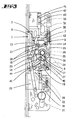
- Fig. 1
- ein Treibstangenschloß mit geöffnetem Dekkel in der Neutralstellung bei zurückgezogenem Riegel,
- Fig. 2
- eine Darstellung gemäß Fig. 1 bei in die Sperrstellung verlagerter Treibstange und aus der Neutralstellung gebrachter Nußhälfte,
- Fig. 3
- eine Darstellung gemäß Fig. 1 mit in die Öffnungsstellung verlagertem TreibstangenAnschlußschieber und entsprechend aus der Neutralstellung verlagerter Nußhälfte,
- Fig. 4
- eine Darstellung gemäß Fig. 1 bei zurückgezogener Falle zufolge Wechselbetätigung,
- Fig. 5
- eine Darstellung gemäß Fig. 1 bei vorgeschlossenem Riegel,
- Fig. 6
- eine Schnittdarstellung durch die beiden Nußhälften in einer ersten Kupplungsstellung,
- Fig. 7
- eine Darstellung gemäß Fig. 6 in einer zweiten Kupplungsstellung,
- Fig. 8
- ein zweites Ausführungsbeispiel der Erfindung in einer Darstellung gemäß Fig. 1,
- Fig. 9
- eine vergrößerte Darstellung des Fallenabschnittes gemäß Fig. 8 und
- Fig. 10
- einen Schnitt gemäß der Linie X-X in Fig. 9.
Claims (15)
- Schloß, insbesondere Treibstangenschloß, mit zwei koaxial zu einer Drückerachse angeordneten Nußhälften (5, 6) und mit einer Falle (1), welche zufolge eines umstellbaren Kupplungsgliedes (11, 47) wahlweise von einer der beiden Nußhälften durch einen bei Drückerbetätigung verschwenkbaren Betätigungsarm (10, 110) zurückziehbar ist,
dadurch gekennzeichnet, daß jede Nußhälfte (5, 6) einen Betätigungsarm (10, 110) besitzt, derart, daß sich die beiden Betätigungsarme (10, 110) in einer Radialebene und mit einem Abstandsraum zueinander befinden,
daß, in einer ersten Alternative, jeder Betätigungsarm eine Aufnahmebohrung für einen Betätigungsstift (11) als Kupplungsglied besitzt, der wahlweise in die Aufnahmebohrung des einen oder anderen Betätigungsarms (10) eingesetzt werden kann, und der Falle (1) ein Betätigungsabschnitt (7) zugeordnet ist, der von dem Betätigungsstift (11) unabhängig von seiner Zuordnung zu dem einen oder anderen Betätigungsarm (10) betätigt werden kann,
oder daß, in einer zweiten Alternative,
der Falle (1) ein Betätigungsabschnitt zugeordnet ist, der einen in axialer Richtung verschiebbaren Anschlag (47) als Kupplungsglied aufweist, das, je nach Lage, von dem einen oder dem anderen Betätigungsarm (110, 110') betätigt werden kann. - Schloß nach Anspruch 1, dadurch gekennzeichnet, daß die Nußhälften (5, 6) aus einer mittleren Neutralstellung verlagerbar sind und mit einem Treibstangen-Anschlußschieber (22) zusammenwirken, welcher von jeder der beiden Nußhälften bei Drükkerbetätigung verlagerbar ist.
- Schloß nach einem oder mehreren der vorhergehenden Ansprüche dadurch gekennzeichnet, daß der Betätigungsabschnitt (7) des Fallenschwanzes umwendbar auf einem insbesondere zylindrischen Fallenschwanzabschnitt (2) sitzt.
- Schloß nach einem oder mehreren der vorhergehenden Ansprüche dadurch gekennzeichnet, daß jede Nußhälfte (5, 6) für sich in einer abgefederten Mittelstellung gehalten ist.
- Schloß nach einem oder mehreren der vorhergehenden Ansprüche gekennzeichnet durch zwei jeweils einer Nußhälfte (5, 6) zugeordnete, im Schloßgehäuse abgefedert gelagerte Schieber (14, 36).
- Schloß nach einem oder mehreren der vorhergehenden Ansprüche gekennzeichnet durch einen unter Ausbildung eines Freiganges mit jeder der beiden Nußhalften (5. 6) zusammenwirkenden Schwenkhebel (19) zum Antrieb des Treibstangen-Anschlußschiebers (22).
- Schloß nach Anspruch 6 gekennzeichnet durch einen in einen Abstandsraum geführten Teilabschnitt (44) des Schwenkhebels (19), welcher in Achsrichtung sich erstreckende Zähne (18) aufweist, von denen jeder mit einer Radialaussparung (17) der ihm zugeordneten Nußhälfte (5, 6) zusammenwirkt.
- Schloß nach einem oder mehreren der vorhergehenden Ansprüche gekennzeichnet durch einen auf die Falle (1), insbesondere auf den Betätigungsabschnitt (7) wirkenden Wechselhebel (13).
- Schloß nach einem oder mehreren der vorhergehenden Ansprüche gekennzeichnet durch eine bei vorgeschlossenem Riegel (29) gesperrte Nuß (5, 6) oder Treibstangen-Anschlußschieber (22).
- Schloß nach Anspruch 9 gekennzeichnet durch ein bei vorgeschlossenem Riegel (29) in den Betätigungsweg der Nuß ragenden, riegelbetätigbaren Sperrschieber (27).
- Schloß nach Anspruch 10 dadurch gekennzeichnet, daß der Sperrschieber (27) mit einer Spermase (25) und mit einem Sperrvorsprung (26) der Nuß (5, 6) zusammenwirkt.
- Schloß nach Anspruch 10 oder 11 dadurch gekennzeichnet, daß der Sperrschieber (27) zwei parallel zueinander verlaufende Sperrzinken (45, 46) aufweist, von denen jeder einer der beiden Nußhälften (5, 6) zugeordnet ist
- Schloß nach einem oder mehreren der vorhergehenden Ansprüche dadurch gekennzeichnet, daß der Anschlag (47) durch Drehen einer Gewindespindel (48) aus dem Bewegungsbereich des einen Nußarmes (110) in den Bewegungsbereich des anderen Nußarmes (110') verlagerbar ist.
- Schloß nach einem oder mehreren der vorhergehenden Ansprüche dadurch gekennzeichnet, daß das Kupplungsglied (47) als in einer Tasche des Betätigungsabschnittes (107) einliegendes Plättchen (47) ausgebildet ist.
- Schloß nach einem oder mehreren der vorhergehenden Ansprüche dadurch gekennzeichnet, daß der Drücker (50) aus zwei in bodenseitig geschlossenen Taschen der Nußhälften (105, 106) einliegenden Hälften besteht, welche mittels eines Kupplungsstiftes (51) drehbar axial miteinander gekuppelt sind.
Applications Claiming Priority (4)
| Application Number | Priority Date | Filing Date | Title |
|---|---|---|---|
| DE4440890 | 1994-11-17 | ||
| DE4440890 | 1994-11-17 | ||
| DE19511871 | 1995-03-31 | ||
| DE19511871A DE19511871A1 (de) | 1994-11-17 | 1995-03-31 | Schloß, insbesondere Treibstangenschloß mit zweigeteilter Drückernuß |
Publications (4)
| Publication Number | Publication Date |
|---|---|
| EP0712987A2 EP0712987A2 (de) | 1996-05-22 |
| EP0712987A3 EP0712987A3 (de) | 1996-10-16 |
| EP0712987B1 EP0712987B1 (de) | 1999-06-09 |
| EP0712987B2 true EP0712987B2 (de) | 2003-05-07 |
Family
ID=25942043
Family Applications (1)
| Application Number | Title | Priority Date | Filing Date |
|---|---|---|---|
| EP95114646A Expired - Lifetime EP0712987B2 (de) | 1994-11-17 | 1995-09-18 | Schloss, insbesondere Treibstangenschloss mit zweigeteilter Drückernuss |
Country Status (4)
| Country | Link |
|---|---|
| EP (1) | EP0712987B2 (de) |
| AT (1) | ATE181132T1 (de) |
| DK (1) | DK0712987T4 (de) |
| ES (1) | ES2134390T5 (de) |
Families Citing this family (10)
| Publication number | Priority date | Publication date | Assignee | Title |
|---|---|---|---|---|
| FR2747422B1 (fr) * | 1996-04-12 | 1999-07-02 | Ferco Int Usine Ferrures | Serrure adaptee a etre encastree dans l'epaisseur d'un ouvrant |
| DE19636134A1 (de) * | 1996-09-06 | 1998-03-12 | Fuhr Carl Gmbh & Co | Schloß, insbesondere Einsteckschloß |
| DE19748443A1 (de) † | 1997-11-03 | 1999-05-06 | Winkhaus Fa August | Treibstangenschloß |
| DE29719611U1 (de) * | 1997-11-05 | 1999-03-11 | Gretsch-Unitas GmbH Baubeschläge, 71254 Ditzingen | Schloß, insbesondere Einsteckschloß für eine Außentür |
| DE19842279A1 (de) * | 1998-09-16 | 2000-03-23 | Fuhr Carl Gmbh & Co | Schloß, insbesondere Treibstangenschloß mit umstellbarer Fallenbetätigbarkeit |
| DE19901661A1 (de) * | 1999-01-18 | 2000-07-27 | Fliether Karl Gmbh & Co | Treibstangenverschluß |
| CH694946A5 (de) * | 2001-01-19 | 2005-09-30 | Msl Schloss Und Beschlaegefabr | Dreipunkt-Treibstangen-Schloss. |
| DE202007017958U1 (de) * | 2007-12-20 | 2009-04-23 | Kfv Karl Fliether Gmbh & Co. Kg | Treibstangenverschluss |
| DE102009029068A1 (de) | 2009-09-01 | 2011-03-03 | Aug. Winkhaus Gmbh & Co. Kg | Schloss |
| GB2534682B (en) * | 2014-12-16 | 2021-05-26 | Spire Mfg Limited | Lock assembly |
Family Cites Families (6)
| Publication number | Priority date | Publication date | Assignee | Title |
|---|---|---|---|---|
| DE451156C (de) * | 1926-04-07 | 1927-10-17 | Martha Wesemeier Geb Kuhnt | Tuerschloss mit umkehrbarer Falle und zwei unabhaengig voneinander bewegbaren Nuessen |
| DE2845957A1 (de) | 1978-10-21 | 1980-04-30 | Fliether Fa Karl | Treibstangenschloss, insbesondere fuer wohnungsabschlusstueren |
| DE4026080C2 (de) | 1990-08-17 | 1994-02-03 | Brumme Elke | Treibstangenschloß |
| DE4041537A1 (de) | 1990-12-22 | 1992-06-25 | Fliether Karl Gmbh & Co | Treibstangenverschluss |
| DE9114609U1 (de) * | 1991-10-16 | 1992-02-06 | BKS GmbH, 5620 Velbert | Türschloß |
| IT1263072B (it) * | 1993-03-24 | 1996-07-24 | Deo Errani | Dispositivo per adattare una serratura antipanico al senso di apertura di una porta,predisporre tale serratura all'apertura solo da un lato ed abilitarne momentaneamente l'apertura dal lato opposto |
-
1995
- 1995-09-18 ES ES95114646T patent/ES2134390T5/es not_active Expired - Lifetime
- 1995-09-18 AT AT95114646T patent/ATE181132T1/de not_active IP Right Cessation
- 1995-09-18 DK DK95114646T patent/DK0712987T4/da active
- 1995-09-18 EP EP95114646A patent/EP0712987B2/de not_active Expired - Lifetime
Also Published As
| Publication number | Publication date |
|---|---|
| EP0712987A2 (de) | 1996-05-22 |
| ES2134390T3 (es) | 1999-10-01 |
| EP0712987A3 (de) | 1996-10-16 |
| ES2134390T5 (es) | 2003-11-01 |
| ATE181132T1 (de) | 1999-06-15 |
| EP0712987B1 (de) | 1999-06-09 |
| DK0712987T4 (da) | 2003-06-02 |
| DK0712987T3 (da) | 2000-01-17 |
Similar Documents
| Publication | Publication Date | Title |
|---|---|---|
| DE10202088B4 (de) | Schloss | |
| DE3806662C2 (de) | Feststellvorrichtung für eine mit einem Türschließer versehene Tür | |
| EP1908900B1 (de) | Schloss mit Schwenkauslöser | |
| EP0712987B2 (de) | Schloss, insbesondere Treibstangenschloss mit zweigeteilter Drückernuss | |
| EP0168001B1 (de) | Treibstangenschloss | |
| DE685943C (de) | Fallenschloss | |
| EP0045348A1 (de) | Permutationsschloss mit einer Nockenscheibe und Zuhaltungsscheiben | |
| EP0799957A2 (de) | Antipanikstange mit Umkehrbarkeit für Nottüren | |
| EP0471976B1 (de) | Treibstangenschloss | |
| DE102005039287B4 (de) | Antipanikschloss | |
| DE3148030A1 (de) | Zahnradantrieb in einem schliesszylinderbetaetigbaren treibstangenschloss mit schubriegel | |
| EP0987391B1 (de) | Treibstangenschloss mit umstellbarer Fallenbetätigbarkeit | |
| EP0239855B1 (de) | Schloss für eine Tür, ein Fenster oder dergleichen | |
| EP0913550B2 (de) | Treibstangenschloss | |
| EP0496076B1 (de) | Treibstangenverschluss | |
| DE69805942T2 (de) | Vorrichtung für die Betätigung eines Panikschlosses von aussen | |
| DE19511871A1 (de) | Schloß, insbesondere Treibstangenschloß mit zweigeteilter Drückernuß | |
| EP0806534B1 (de) | Treibstangenschloss | |
| DE2605763C3 (de) | Treibstangenschloß mit Falle | |
| EP0990758A2 (de) | Zusatzschloss an einem Treibstangenverschluss | |
| EP0795665A2 (de) | Einsteckschloss | |
| EP0790376B1 (de) | Treibstangenverschluss | |
| DE2743091A1 (de) | Schloss | |
| DE3709408C2 (de) | ||
| DE9207865U1 (de) | Durch einen Schlüssel- und/oder durch einen Drücker betätigbares Antipanik-Hotelschloß |
Legal Events
| Date | Code | Title | Description |
|---|---|---|---|
| PUAI | Public reference made under article 153(3) epc to a published international application that has entered the european phase |
Free format text: ORIGINAL CODE: 0009012 |
|
| AK | Designated contracting states |
Kind code of ref document: A2 Designated state(s): AT BE CH DE DK ES FR GB IE IT LI NL SE |
|
| PUAL | Search report despatched |
Free format text: ORIGINAL CODE: 0009013 |
|
| RHK1 | Main classification (correction) |
Ipc: E05B 63/04 |
|
| AK | Designated contracting states |
Kind code of ref document: A3 Designated state(s): AT BE CH DE DK ES FR GB IE IT LI NL SE |
|
| 17P | Request for examination filed |
Effective date: 19970127 |
|
| GRAG | Despatch of communication of intention to grant |
Free format text: ORIGINAL CODE: EPIDOS AGRA |
|
| 17Q | First examination report despatched |
Effective date: 19981020 |
|
| GRAG | Despatch of communication of intention to grant |
Free format text: ORIGINAL CODE: EPIDOS AGRA |
|
| GRAH | Despatch of communication of intention to grant a patent |
Free format text: ORIGINAL CODE: EPIDOS IGRA |
|
| GRAH | Despatch of communication of intention to grant a patent |
Free format text: ORIGINAL CODE: EPIDOS IGRA |
|
| GRAA | (expected) grant |
Free format text: ORIGINAL CODE: 0009210 |
|
| AK | Designated contracting states |
Kind code of ref document: B1 Designated state(s): AT BE CH DE DK ES FR GB IE IT LI NL SE |
|
| PG25 | Lapsed in a contracting state [announced via postgrant information from national office to epo] |
Ref country code: SE Free format text: THE PATENT HAS BEEN ANNULLED BY A DECISION OF A NATIONAL AUTHORITY Effective date: 19990609 |
|
| REF | Corresponds to: |
Ref document number: 181132 Country of ref document: AT Date of ref document: 19990615 Kind code of ref document: T |
|
| REG | Reference to a national code |
Ref country code: CH Ref legal event code: EP |
|
| REF | Corresponds to: |
Ref document number: 59506154 Country of ref document: DE Date of ref document: 19990715 |
|
| REG | Reference to a national code |
Ref country code: CH Ref legal event code: NV Representative=s name: R. A. EGLI & CO. PATENTANWAELTE |
|
| GBT | Gb: translation of ep patent filed (gb section 77(6)(a)/1977) |
Effective date: 19990628 |
|
| REG | Reference to a national code |
Ref country code: IE Ref legal event code: FG4D Free format text: GERMAN |
|
| ET | Fr: translation filed | ||
| ITF | It: translation for a ep patent filed | ||
| REG | Reference to a national code |
Ref country code: ES Ref legal event code: FG2A Ref document number: 2134390 Country of ref document: ES Kind code of ref document: T3 |
|
| REG | Reference to a national code |
Ref country code: DK Ref legal event code: T3 |
|
| PLBQ | Unpublished change to opponent data |
Free format text: ORIGINAL CODE: EPIDOS OPPO |
|
| PLBI | Opposition filed |
Free format text: ORIGINAL CODE: 0009260 |
|
| PLBF | Reply of patent proprietor to notice(s) of opposition |
Free format text: ORIGINAL CODE: EPIDOS OBSO |
|
| PLBF | Reply of patent proprietor to notice(s) of opposition |
Free format text: ORIGINAL CODE: EPIDOS OBSO |
|
| 26 | Opposition filed |
Opponent name: AUGUST WINKHAUS GMBH & CO. KG Effective date: 20000302 |
|
| NLR1 | Nl: opposition has been filed with the epo |
Opponent name: AUGUST WINKHAUS GMBH & CO. KG |
|
| REG | Reference to a national code |
Ref country code: GB Ref legal event code: IF02 |
|
| PLAW | Interlocutory decision in opposition |
Free format text: ORIGINAL CODE: EPIDOS IDOP |
|
| PLAW | Interlocutory decision in opposition |
Free format text: ORIGINAL CODE: EPIDOS IDOP |
|
| PUAH | Patent maintained in amended form |
Free format text: ORIGINAL CODE: 0009272 |
|
| STAA | Information on the status of an ep patent application or granted ep patent |
Free format text: STATUS: PATENT MAINTAINED AS AMENDED |
|
| 27A | Patent maintained in amended form |
Effective date: 20030507 |
|
| AK | Designated contracting states |
Designated state(s): AT BE CH DE DK ES FR GB IE IT LI NL SE |
|
| REG | Reference to a national code |
Ref country code: CH Ref legal event code: AEN Free format text: AUFRECHTERHALTUNG DES PATENTES IN GEAENDERTER FORM |
|
| REG | Reference to a national code |
Ref country code: DK Ref legal event code: EBP |
|
| GBTA | Gb: translation of amended ep patent filed (gb section 77(6)(b)/1977) | ||
| NLR2 | Nl: decision of opposition |
Effective date: 20030507 |
|
| NLR3 | Nl: receipt of modified translations in the netherlands language after an opposition procedure | ||
| ET3 | Fr: translation filed ** decision concerning opposition | ||
| REG | Reference to a national code |
Ref country code: ES Ref legal event code: DC2A Date of ref document: 20030523 Kind code of ref document: T5 |
|
| PGFP | Annual fee paid to national office [announced via postgrant information from national office to epo] |
Ref country code: ES Payment date: 20050909 Year of fee payment: 11 |
|
| REG | Reference to a national code |
Ref country code: ES Ref legal event code: FD2A Effective date: 20060919 |
|
| PG25 | Lapsed in a contracting state [announced via postgrant information from national office to epo] |
Ref country code: ES Free format text: LAPSE BECAUSE OF NON-PAYMENT OF DUE FEES Effective date: 20060919 |
|
| PGFP | Annual fee paid to national office [announced via postgrant information from national office to epo] |
Ref country code: DK Payment date: 20080929 Year of fee payment: 14 Ref country code: CH Payment date: 20080926 Year of fee payment: 14 |
|
| PGFP | Annual fee paid to national office [announced via postgrant information from national office to epo] |
Ref country code: IT Payment date: 20080924 Year of fee payment: 14 Ref country code: IE Payment date: 20080919 Year of fee payment: 14 Ref country code: AT Payment date: 20080923 Year of fee payment: 14 |
|
| PGFP | Annual fee paid to national office [announced via postgrant information from national office to epo] |
Ref country code: DE Payment date: 20080930 Year of fee payment: 14 |
|
| PGFP | Annual fee paid to national office [announced via postgrant information from national office to epo] |
Ref country code: BE Payment date: 20080929 Year of fee payment: 14 |
|
| PGFP | Annual fee paid to national office [announced via postgrant information from national office to epo] |
Ref country code: NL Payment date: 20090923 Year of fee payment: 15 |
|
| BERE | Be: lapsed |
Owner name: KARL *FLIETHER G.M.B.H. & CO. Effective date: 20090930 |
|
| REG | Reference to a national code |
Ref country code: CH Ref legal event code: PL |
|
| REG | Reference to a national code |
Ref country code: DK Ref legal event code: EBP |
|
| REG | Reference to a national code |
Ref country code: IE Ref legal event code: MM4A |
|
| PG25 | Lapsed in a contracting state [announced via postgrant information from national office to epo] |
Ref country code: AT Free format text: LAPSE BECAUSE OF NON-PAYMENT OF DUE FEES Effective date: 20090918 |
|
| PG25 | Lapsed in a contracting state [announced via postgrant information from national office to epo] |
Ref country code: IE Free format text: LAPSE BECAUSE OF NON-PAYMENT OF DUE FEES Effective date: 20090918 Ref country code: DE Free format text: LAPSE BECAUSE OF NON-PAYMENT OF DUE FEES Effective date: 20100401 |
|
| PG25 | Lapsed in a contracting state [announced via postgrant information from national office to epo] |
Ref country code: BE Free format text: LAPSE BECAUSE OF NON-PAYMENT OF DUE FEES Effective date: 20090930 |
|
| PG25 | Lapsed in a contracting state [announced via postgrant information from national office to epo] |
Ref country code: LI Free format text: LAPSE BECAUSE OF NON-PAYMENT OF DUE FEES Effective date: 20090930 Ref country code: CH Free format text: LAPSE BECAUSE OF NON-PAYMENT OF DUE FEES Effective date: 20090930 |
|
| PGFP | Annual fee paid to national office [announced via postgrant information from national office to epo] |
Ref country code: GB Payment date: 20100929 Year of fee payment: 16 |
|
| PG25 | Lapsed in a contracting state [announced via postgrant information from national office to epo] |
Ref country code: DK Free format text: LAPSE BECAUSE OF NON-PAYMENT OF DUE FEES Effective date: 20090930 |
|
| PG25 | Lapsed in a contracting state [announced via postgrant information from national office to epo] |
Ref country code: IT Free format text: LAPSE BECAUSE OF NON-PAYMENT OF DUE FEES Effective date: 20090918 |
|
| REG | Reference to a national code |
Ref country code: NL Ref legal event code: V1 Effective date: 20110401 |
|
| REG | Reference to a national code |
Ref country code: FR Ref legal event code: ST Effective date: 20110531 |
|
| PG25 | Lapsed in a contracting state [announced via postgrant information from national office to epo] |
Ref country code: FR Free format text: LAPSE BECAUSE OF NON-PAYMENT OF DUE FEES Effective date: 20100930 |
|
| PG25 | Lapsed in a contracting state [announced via postgrant information from national office to epo] |
Ref country code: NL Free format text: LAPSE BECAUSE OF NON-PAYMENT OF DUE FEES Effective date: 20110401 |
|
| PGFP | Annual fee paid to national office [announced via postgrant information from national office to epo] |
Ref country code: FR Payment date: 20091006 Year of fee payment: 15 |
|
| GBPC | Gb: european patent ceased through non-payment of renewal fee |
Effective date: 20110918 |
|
| PG25 | Lapsed in a contracting state [announced via postgrant information from national office to epo] |
Ref country code: GB Free format text: LAPSE BECAUSE OF NON-PAYMENT OF DUE FEES Effective date: 20110918 |