EP0806534B1 - Treibstangenschloss - Google Patents
Treibstangenschloss Download PDFInfo
- Publication number
- EP0806534B1 EP0806534B1 EP97113389A EP97113389A EP0806534B1 EP 0806534 B1 EP0806534 B1 EP 0806534B1 EP 97113389 A EP97113389 A EP 97113389A EP 97113389 A EP97113389 A EP 97113389A EP 0806534 B1 EP0806534 B1 EP 0806534B1
- Authority
- EP
- European Patent Office
- Prior art keywords
- driving rod
- lock
- connecting slide
- rod connecting
- closure according
- Prior art date
- Legal status (The legal status is an assumption and is not a legal conclusion. Google has not performed a legal analysis and makes no representation as to the accuracy of the status listed.)
- Expired - Lifetime
Links
Images


Classifications
-
- E—FIXED CONSTRUCTIONS
- E05—LOCKS; KEYS; WINDOW OR DOOR FITTINGS; SAFES
- E05C—BOLTS OR FASTENING DEVICES FOR WINGS, SPECIALLY FOR DOORS OR WINDOWS
- E05C9/00—Arrangements of simultaneously actuated bolts or other securing devices at well-separated positions on the same wing
- E05C9/02—Arrangements of simultaneously actuated bolts or other securing devices at well-separated positions on the same wing with one sliding bar for fastening when moved in one direction and unfastening when moved in opposite direction; with two sliding bars moved in the same direction when fastening or unfastening
- E05C9/021—Arrangements of simultaneously actuated bolts or other securing devices at well-separated positions on the same wing with one sliding bar for fastening when moved in one direction and unfastening when moved in opposite direction; with two sliding bars moved in the same direction when fastening or unfastening with rack and pinion mechanism
- E05C9/023—Arrangements of simultaneously actuated bolts or other securing devices at well-separated positions on the same wing with one sliding bar for fastening when moved in one direction and unfastening when moved in opposite direction; with two sliding bars moved in the same direction when fastening or unfastening with rack and pinion mechanism between a lock cylinder and the bar
-
- E—FIXED CONSTRUCTIONS
- E05—LOCKS; KEYS; WINDOW OR DOOR FITTINGS; SAFES
- E05B—LOCKS; ACCESSORIES THEREFOR; HANDCUFFS
- E05B63/00—Locks or fastenings with special structural characteristics
- E05B63/06—Locks or fastenings with special structural characteristics with lengthwise-adjustable bolts ; with adjustable backset, i.e. distance from door edge
Definitions
- the invention relates to an espagnolette lock according to the preamble of Claim 1.
- espagnolette lock according to the preamble of Claim 1.
- Constructions are concerned usually around a castle with a Reduction gear, a lock gear operated, Espagnolette connecting slide that can be moved parallel to the faceplate and according to one of them Actuating rod connecting slide assigned stop Exchange lever lockable across the faceplate Cases.
- the object of the invention is based on the object with a generic espagnolette lock, the changing function to improve.
- This task is solved with a generic Espagnolette lock in that an espagnolette return spring, which one of the connecting rod connecting slide assigned stop surface when changing operation is excited.
- the elasticity of this drive rod connecting slide return spring is sufficient to the connecting rod slide and any existing drive rod closures to independently return to the neutral position.
- This stop surface can be from an abutting edge of the connecting slide.
- the spring can also be the transmission medium around the Teibstangenan gleichchlingung on the Transfer lever.
- the spring can be in Lay the intermediate layer between the edge and the change lever.
- Another way of realizing this idea is that the connecting slide the change lever immediately applied. Then on the connecting rod slide a cam or a separate step be provided, which forms the stop surface, which acts on the drive rod return spring.
- the espagnolette lock has one with a faceplate 1 connected lock housing 2.
- the faceplate 1 protrudes on both sides the lock housing 2 and overlaps an upper and lower drive rod emerging from the lock housing 2 3, 4.
- latch members not shown provided with the door frame side, also Counter-parts not shown cooperate.
- roller trap 7 designed trap.
- the lock housing 2 In the upper area of the lock housing 2 is between a castle floor 5 and a castle ceiling 6 as Roller trap 7 designed trap.
- it is composed of a faceplate opening 8 penetrating box-shaped profile section 9, which coupled with a latch tail 10 projecting into the lock is.
- the box-shaped one is supported around a vertical axis Profile section 9 a role above this 11.
- a trap slope having trap head can be used.
- a nut housing 12 is integrated. This stores a one equipped with a square opening Lock nut 13. On a protruding nut arm 14 engages a slide 16 acted upon by a compression spring 15 on. The displacement of the lock nut 13 is limited Clockwise direction by a projection 17 of the Lock housing 12, on which projection an arm 18th the lock nut 13 supports, cf. in particular Figure 3. Furthermore, the lock nut 13 forms an upstanding Fall retraction arm 19, which with a shoulder 20th of the trap tail 10 cooperates.
- a support plate 21 is fixed on the lock base 5. This supports a ring gear 23 in a bore 22 Hole 22 is from a lock cylinder insertion opening 24 for a not illustrated, as a profile cylinder designed locking cylinder crossed.
- the cylinder core axis lies offset to the central axis of the Sprocket 23, below it.
- the ring gear 23 has a radially directed gap 25 for engaging a locking bit of the profile locking cylinder Mistake.
- the drive rod connecting slide 27 is coupled with the lower drive rod 4 while the opposite connecting rod connecting slide 28 entrains the upper drive rod 3.
- the connecting rod connecting slide 28 then still serves to drive the below the roller latch 7 guided bolt 29.
- the drive means are not essential to the invention and therefore not illustrated in detail.
- the retraction of the roller latch 7 by means of the lock cylinder actuation is possible via a change lever 30.
- the alignment of the change lever 30 runs approximately parallel to the faceplate 1.
- the change lever 30 has two arms designed and has the longer lever arm 34 and shorter lever arm 35.
- the longer lever arm 34 extends is parallel to faceplate 1 and ends at the end a step into an end section facing the lock 34 'over. This dips into a pocket trained receiving space 36 of the trap tail 10 on.
- a fixed stop 39 which in the embodiment is designed as a grub screw.
- the grub screw fixed stop 39 passes through a bore 40 of the faceplate 1 and is in an internal thread 41 of a bearing block 42 screwed in. A is used to hold it forend countersunk screw 43.
- the free end of the Set screw 39 stops against a step 44 of the longer lever arm 34.
- the shorter lever arm 35 forms an approximately perpendicular to Forend 1 extending shoulder 35 'and lies in the Path of movement of a butt edge 27 'of the led on the faceplate 1 Espagnolette connecting slide 27.
- a torsion spring 45 On the pin 33 for the change lever 30 is a torsion spring 45 inserted. One end 45 'of which is supported on a recess 46 of the bearing block 42. The other End 45 '' lies in a relaxed position in front of the shoulder 35 'of the shorter lever arm 35.
- This torsion spring 45 is used as drive rod return spring. Their travel corresponds preferably the maximum swivel path of the change lever 30th
- the retraction of the roller latch 7 can be done in a known manner on the one hand by the lock nut 13.
- the stop 38 of the catch tail 10 acts on the change lever and pivots it.
- the bolt 29 is closed from its pre-closing position by key actuation.
- the ring gear 23 is dragged clockwise.
- the connecting rod connecting slide 27 experiences an upward shift.
- the key can then be removed from the locking cylinder.
- the abutting edge 27 ' is in contact with one end 45''of the drive rod return spring 45.
- the roller trap 7 can be retracted by continuing the return rotation of the cylinder core in a clockwise direction.
- the connecting rod connecting slide 27 moves further in the upward direction and acts upon the shorter lever arm 35 of the change-over lever 30, with the end 45 ′′ of the return spring 45 being interposed, connected to a pivoting thereof.
- Its longer lever arm 34 acts on the stop 37 and pulls the latch 7 back against the force of the latch spring 31 loading it.
- the drive rod return spring 45 is charged.
- the latch spring 31 causes the latch 7 to advance, taking the change lever 30 with it. The advance of the roller latch 7 is limited when the change lever 34 acts on the grub screw fixed stop 39.
- the connecting rod return spring 45 relaxes, the movable end 45 ′′ of which pushes the connecting rod connecting slide 27 back into the basic position according to FIG.
- the ring gear is rotated via the reduction gear, taking the locking member of the locking cylinder with it, so that the key can then be removed from the locking cylinder without further locking rotation.
- the fixed stop could also be a quick adjustment enable, for example via control curves Etc..
- the spring 45 which acts on the abutting edge 27 ' has such a strength that it is under tension both the connecting rod connecting slide, as well as with it connected locking elements and the gear transmission together with the lock cylinder can push back when the cylinder is actuated stops at the change operation.
- the Torsion spring 45 is due to the small travel of their Arm 45 '' tensioned only when changing the switch.
- the change lever 30 shifted because in the intermediate position of the spring arm 45 ' Change lever arm 35 acted on the abutting edge 35 ' becomes.
- FIG. 8-12 acts on a butt edge 27 'of the connecting rod connecting slide 27 immediately a mating edge 35 'of the lever arm 35 of the change lever 30.
- the connecting rod connecting slide return spring 45 '' is included by a cam 51, which also the rod connecting slide 27 is arranged, acted upon. there the cam 51 kicks against the end 45 "of the spring 45.
- the spring 45 is a spiral spring and on the other side in Lock housing anchored non-rotatably.
- the coil spring 45 is wrapped around a pin 33, which at the same time the Forms axis of rotation of the change lever 30.
- the connecting rod connecting slide can including the drive gear and any existing Push rod locks moved back to the neutral position if the lock operation is canceled becomes.
- a butt edge 35 ' the lever arm 35 of the change lever 30 acted upon. By pivoting the change lever 30 then retracting the trap.
- the last wheel 26 a small diameter toothing 26 ", which with correspondingly opposite toothing of the drive rods 27, 28 cooperates so that by rotating the Gear 26, the two drive rods 27, 28 in the opposite direction be relocated.
- the last wheel 26 has a larger diameter Toothing on.
- This toothing meshes with a toothing of an upstream drive wheel.
- the toothing with a larger diameter has a peripheral region 26 ', which is not toothed.
- the location of the toothless Area 26 ' is selected so that when actuated the espagnolette lock, especially the toothed drive it is ensured that the drive gear of the upstream gear always in the toothed area of the last wheel intervenes. But it provided that at a drive rod displacement from that shown in Figure 8 Neutral position in that shown in Figure 11 Locking position of the cam 51 of the connecting rod connecting slide 27 through the toothless area 26 'of the last wheel 26 dives.
- the connecting rod connecting slide 26 runs in the exemplary embodiment immediately adjacent to the cuff 1.
- the toothed area of the last wheel 26 with larger diameter but has such a diameter that it Espagnolette connecting slide protrudes and almost up to protrudes immediately in front of the cuff 1.
- the diameter advantageously corresponds to Larger toothing of the last wheel 26 approximately the distance between cuff 1 and handle housing 12 or Nut 13.
Landscapes
- Engineering & Computer Science (AREA)
- Structural Engineering (AREA)
- Mechanical Engineering (AREA)
- Lock And Its Accessories (AREA)
- Orthopedics, Nursing, And Contraception (AREA)
- Mechanical Control Devices (AREA)
Description
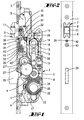
- Figur 1
- eine Ansicht eines erfindungsgemäß gestalteten Treibstangenschlosses bei fortgelassener Schloßdecke mit Blick auf das Schloßeingerichte, betreffend die Vorschließstellung des Riegels,
- Figur 2
- eine Ansicht gegen den Stulp des Treibstangenschlosses,
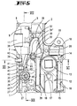
- Figur 3
- in vergrößerter Darstellung das Treibstangenschloß im Bereich der als Rollenfalle gestalteten Falle, ebenfalls die Schließstellung betreffend,
- Figur 4
- eine der Figur 1 entsprechende Darstellung, wobei der Riegel zurückgeschlossen ist,
- Figur 5
- eine der Figur 3 entsprechende Darstellung, wobei jedoch durch Wechselhebelbetätigung über den Wechselhebel die Rollenfalle schloßeinwärts gezogen ist,
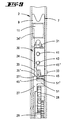
- Figur 6
- den Schnitt nach der Linie VI-VI in Figur 5,
- Figur 7
- den Schnitt nach der Linie VII-VII in Figur 5,
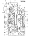
- Figur 8
- ein zweites Ausführungsbeispiel der Erfindung in der Neutralstellung,
- Figur 9
- ein Schloß gemäß Figur 8 in fallenseitiger Ansicht bei abgenommener Stulpschiene,
- Figur 10
- ein Schloß gemäß Figur 8 bei Wechselbetätigung,
- Figur 11
- ein Schloß gemäß Figur 8 in der Verriegelungsstellung,
- Figur 12
- eine Ansicht gemäß Figur 9 in Stellung gemäß Figur 11.
Das Zurückziehen der Rollenfalle 7 kann in bekannter Weise einerseits durch die Schloßnuß 13 geschehen. Nach Durchlauf eines entsprechenden Spiels beaufschlagt dabei der Anschlag 38 des Fallenschwanzes 10 den Wechselhebel und verschwenkt diesen. Das Zurückschließen des Riegels 29 aus seiner Vorschließstellung geschieht durch Schlüsselbetätigung. Dabei wird der Zahnkranz 23 in Uhrzeigerrichtung mitgeschleppt. Über das Letztrad 26 des Untersetzungsgetriebes U erfährt der Treibstangenanschlußschieber 27 eine Aufwärtsverlagerung. In der Rückschließstellung gemäß Figur 3 läßt sich sodann der Schlüssel aus dem Schließzylinder abziehen. Dann befindet sich die Stoßkante 27' in Anlage an dem einen Ende 45'' der Treibstangenrückdrückfeder 45. Aus dieser Stellung heraus läßt sich durch Fortsetzen der Rückschließdrehung des Zylinderkerns in Uhrzeigerrichtung die Rollenfalle 7 zurückziehen. Hierbei fährt der Treibstangenanschlußschieber 27 weiter in Aufwärtsrichtung und beaufschlagt unter Zwischenlage des Endes 45'' der Rückdrückfeder 45 den kürzeren Hebelarm 35 des Wechselhebels 30, verbunden mit einem Verschwenken desselben. Dessen längerer Hebelarm 34 beaufschlagt den Anschlag 37 und zieht die Falle 7 entgegen der Kraft der sie belastenden Fallenfeder 31 zurück. Bei diesem Vorgang wird die Treibstangenrückdrückfeder 45 aufgeladen. Nach Beenden der Schließdrehung bewirkt die Fallenfeder 31 ein Vortreten der Falle 7 unter Mitnahme des Wechselhebels 30. Begrenzt ist der Vortritt der Rollenfalle 7, wenn der Wechselhebel 34 den Madenschrauben-Festanschlag 39 beaufschlagt. Gleichzeitig mit diesem Vorgang entspannt sich die Treibstangenrückdrückfeder 45, deren bewegliches Ende 45'' den Treibstangenanschlußschieber 27 in die Grundstellung gemäß Figur 4 zurückverlagert. Einhergehend mit dessen Bewegung wird der Zahnkranz über das Untersetzungsgetriebe gedreht unter Mitnahme des Schließgliedes des Schließzylinders, so daß dann der Schlüssel aus dem Schließzylinder ohne weitere Schließdrehung abziehbar ist.
Claims (9)
- Treibstangenschloß oder -Verschluß mit einem zahnradgetriebenen aus einer ersten, einer Freigabestellung entsprechenden Stellung in eine zweite, einer Verriegelungsstellung entsprechenden Stellung verlagerbaren Treibstangenanschlußschieber (27), mit einer von einem Schließzylinder oder dergleichen gegen die Rückstellkraft einer Fallenfeder (31) wechselbetätigbaren Falle (7), wobei ein Wechselhebel (30) einhergehend mit dem über die erste Stellung hinaus in eine dritte, einer Wechselbetätigungsstellung entsprechenden Stellung verlagerbaren Treibstangenanschlußschieber (27) betätigbar ist, gekennzeichnet durch eine an einer Anschlagfläche (27', 51') des Treibstangenanschlußschiebers angreifende, von der Fallenfeder (31) verschiedene Treibstangen-Rückdrückfeder (45), die beim Übergang von der ersten in die dritte Stellung gespannt wird und deren Elastizität ausreicht, den Treibstangenanschlußschieber (27, 28) und gegebenenfalls Treibstangenverschlüsse selbständig in die erste Stellung zurückzuverlagern.
- Treibstangenschloß oder -Verschluß nach Anspruch 1, gekennzeichnet durch zwei gegenläufig verlagerbare Treibstangenanschlußschieber (27, 28) welche von einem mit seiner Abtriebsverzahnung in eine Verzahnung des Treibstangenanschlußschiebers (27, 28) eingreifenden Letztrad (26) eines Zahnradgetriebes angetrieben werden.
- Treibstangenschloß oder -Verschluß nach einem der vorhergehenden Ansprüche, dadurch gekennzeichnet, daß der Treibstangenanschlußschieber (27) unmittelbar benachbart zur Stulpe (1) läuft.
- Treibstangenschloß oder -Verschluß nach einem der vorhergehenden Ansprüche, dadurch gekennzeichnet, daß die Treibsangenanschlußschieber-Rückdrückfeder (45) an einem Nocken (51) des Treibstangenanschlußschiebers (27) angreift.
- Treibstangenschloß oder -Verschluß nach Anspruch 4, dadurch gekennzeichnet, daß der Nocken (51) einen zahnfreien Bereich (26') der Abtriebsverzahnung des Letztrades (26) durchläuft, insbesondere beim Übergang von der ersten in die zweite Stellung.
- Treibstangenschloß oder -Verschluß nach einem der vorhergehenden Ansprüche, dadurch gekennzeichnet, daß der Durchmesser der Abtriebsverzahnung des Letztrades (26) in etwa dem Abstandsmaß von Drückernuß (13) oder Drückernußgehäuse (12) und Stulpe (1) entspricht.
- Treibstangenschloß oder -Verschluß nach einem der vorhergehenden Ansprüche, dadurch gekennzeichnet, daß die Anschlagfläche (27') unter Zwischenlage der Treibstangenrückdrückfeder (45) den Wechselhebel (30) beaufschlagt, wobei der Federweg der Treibstangenrückdrückfeder (45) bevorzugt dem maximalen Schwenkweg des Wechselhebels (30) entspricht.
- Treibstangenschloß oder -Verschluß nach einem der vorhergehenden Ansprüche, dadurch gekennzeichnet, daß das Übersetzungsverhältnis der Wechselarme (35, 34) 1:10 ist, wobei bevorzugt mit einem Verlagerungsweg des Treibstangenanschlußschiebers um 1 bis 1,3 mm ein Fallenverschlußweg von 10 mm einhergeht.
- Treibstangenschloß oder -Verschluß nach einem der vorhergehenden Ansprüche, dadurch gekennzeichnet, daß die Treibstangen-Rückdrückfeder (45) nur bei der Wechselfunktion gespannt wird.
Applications Claiming Priority (5)
| Application Number | Priority Date | Filing Date | Title |
|---|---|---|---|
| DE4322457 | 1993-07-06 | ||
| DE4322457 | 1993-07-06 | ||
| DE4405816A DE4405816C2 (de) | 1993-07-06 | 1994-02-23 | Treibstangenschloß |
| DE4405816 | 1994-02-23 | ||
| EP94105749A EP0633379B1 (de) | 1993-07-06 | 1994-04-14 | Treibstangenschloss |
Related Parent Applications (2)
| Application Number | Title | Priority Date | Filing Date |
|---|---|---|---|
| EP94105749.9 Division | 1994-04-14 | ||
| EP94105749A Division EP0633379B1 (de) | 1993-07-06 | 1994-04-14 | Treibstangenschloss |
Publications (3)
| Publication Number | Publication Date |
|---|---|
| EP0806534A2 EP0806534A2 (de) | 1997-11-12 |
| EP0806534A3 EP0806534A3 (de) | 1998-03-11 |
| EP0806534B1 true EP0806534B1 (de) | 2003-06-04 |
Family
ID=6492078
Family Applications (1)
| Application Number | Title | Priority Date | Filing Date |
|---|---|---|---|
| EP97113389A Expired - Lifetime EP0806534B1 (de) | 1993-07-06 | 1994-04-14 | Treibstangenschloss |
Country Status (2)
| Country | Link |
|---|---|
| EP (1) | EP0806534B1 (de) |
| DE (3) | DE4405816C2 (de) |
Families Citing this family (3)
| Publication number | Priority date | Publication date | Assignee | Title |
|---|---|---|---|---|
| DE29722665U1 (de) * | 1997-12-22 | 1998-03-05 | Hoppe Holding AG, Müstair | Antrieb für die Betätigung von Funktionselementen |
| DE10243890B3 (de) * | 2002-09-21 | 2004-05-27 | Carl Fuhr Gmbh & Co. Kg | Treibstangenschloß |
| AT510092B1 (de) * | 2010-07-07 | 2012-04-15 | Roto Frank Ag | Schloss |
Family Cites Families (4)
| Publication number | Priority date | Publication date | Assignee | Title |
|---|---|---|---|---|
| DE7908341U1 (de) * | 1979-03-24 | 1983-11-03 | Fa. Karl Fliether, 5620 Velbert | Tuerschloss, insbesondere einsteckschloss |
| FR2469537A1 (fr) * | 1979-11-15 | 1981-05-22 | Gilro | Serrure automatique pour porte d'entree |
| DE3836694C2 (de) * | 1988-10-28 | 1996-05-09 | Fliether Karl Gmbh & Co | Treibstangenschloß |
| DE4014041A1 (de) * | 1990-05-02 | 1991-11-07 | Fuhr Carl Gmbh & Co | Schliesszylinderbetaetigbares treibstangenschloss |
-
1994
- 1994-02-23 DE DE4405816A patent/DE4405816C2/de not_active Expired - Lifetime
- 1994-04-14 DE DE59407112T patent/DE59407112D1/de not_active Expired - Fee Related
- 1994-04-14 DE DE59410294T patent/DE59410294D1/de not_active Expired - Fee Related
- 1994-04-14 EP EP97113389A patent/EP0806534B1/de not_active Expired - Lifetime
Also Published As
| Publication number | Publication date |
|---|---|
| DE59407112D1 (de) | 1998-11-26 |
| EP0806534A2 (de) | 1997-11-12 |
| DE59410294D1 (de) | 2003-07-10 |
| DE4405816C2 (de) | 2002-11-21 |
| EP0806534A3 (de) | 1998-03-11 |
| DE4405816A1 (de) | 1995-01-19 |
Similar Documents
| Publication | Publication Date | Title |
|---|---|---|
| DE3447748C2 (de) | ||
| DE3605826A1 (de) | Treibstangenverschluss mit handhabenrueckfuehrung | |
| DE3505379C1 (de) | Treibstangenschloß | |
| DE69808030T2 (de) | Treibstangenschloss für eine Tür, Fenstertür oder dergleichen | |
| EP0168001B1 (de) | Treibstangenschloss | |
| EP0907815A1 (de) | Verschluss für türen, hauben, klappen od. dgl., insbesondere von fahrzeugen, wie kraftfahrzeugen | |
| EP0954667B1 (de) | Schloss mit falle für tür oder fenster | |
| EP1020594A2 (de) | Treibstangenverschluss | |
| DE4014046C2 (de) | Schließzylinderbetätigbares Treibstangenschloß | |
| EP1020597A1 (de) | Treibstangenverschluss mit einem Hauptschloss und einem Nebenschloss | |
| EP0515922B1 (de) | Permutationsschloss, insbesondere für Koffer, Möbel oder dergleichen | |
| EP0485767B1 (de) | Verschluss für den Flügel, insbesondere Schiebeflügel eines Fensters, einer Tür od.dgl. | |
| DE4114007A1 (de) | Treibstangenverschluss | |
| DE3148030A1 (de) | Zahnradantrieb in einem schliesszylinderbetaetigbaren treibstangenschloss mit schubriegel | |
| EP0806534B1 (de) | Treibstangenschloss | |
| DE3520861A1 (de) | Rueckdruecksperre an treibstangenbeschlaegen, insbesondere schluesselbetaetigbaren treibstangenschloessern | |
| EP0581338B1 (de) | Schliesszylinderbetätigbares Treibstangenschloss | |
| DE69800295T2 (de) | Treibstangenbeschlag oder Treibstangenverschluß für Tür, Fenster oder dergl. | |
| EP1672153B1 (de) | Schloss mit Riegel und Riegelantrieb | |
| DE3427713A1 (de) | Mehrtourig schliessendes treibstangenschloss | |
| EP0454960B1 (de) | Treibstangenschloss | |
| AT394607B (de) | Mehrfachverriegelung | |
| EP0496076B1 (de) | Treibstangenverschluss | |
| EP0974721B1 (de) | Mehrriegelschloss | |
| EP0633379B1 (de) | Treibstangenschloss |
Legal Events
| Date | Code | Title | Description |
|---|---|---|---|
| PUAI | Public reference made under article 153(3) epc to a published international application that has entered the european phase |
Free format text: ORIGINAL CODE: 0009012 |
|
| AC | Divisional application: reference to earlier application |
Ref document number: 633379 Country of ref document: EP |
|
| AK | Designated contracting states |
Kind code of ref document: A2 Designated state(s): AT DE FR GB IT |
|
| PUAL | Search report despatched |
Free format text: ORIGINAL CODE: 0009013 |
|
| AK | Designated contracting states |
Kind code of ref document: A3 Designated state(s): AT DE FR GB IT |
|
| 17P | Request for examination filed |
Effective date: 19980522 |
|
| 17Q | First examination report despatched |
Effective date: 20000105 |
|
| GRAH | Despatch of communication of intention to grant a patent |
Free format text: ORIGINAL CODE: EPIDOS IGRA |
|
| GRAH | Despatch of communication of intention to grant a patent |
Free format text: ORIGINAL CODE: EPIDOS IGRA |
|
| GRAA | (expected) grant |
Free format text: ORIGINAL CODE: 0009210 |
|
| RAP1 | Party data changed (applicant data changed or rights of an application transferred) |
Owner name: CARL FUHR GMBH & CO. KG |
|
| AC | Divisional application: reference to earlier application |
Ref document number: 0633379 Country of ref document: EP Kind code of ref document: P |
|
| AK | Designated contracting states |
Designated state(s): AT DE FR GB IT |
|
| REG | Reference to a national code |
Ref country code: GB Ref legal event code: FG4D Free format text: NOT ENGLISH |
|
| GBT | Gb: translation of ep patent filed (gb section 77(6)(a)/1977) | ||
| REF | Corresponds to: |
Ref document number: 59410294 Country of ref document: DE Date of ref document: 20030710 Kind code of ref document: P |
|
| ET | Fr: translation filed | ||
| PGFP | Annual fee paid to national office [announced via postgrant information from national office to epo] |
Ref country code: GB Payment date: 20040406 Year of fee payment: 11 |
|
| PLBE | No opposition filed within time limit |
Free format text: ORIGINAL CODE: 0009261 |
|
| STAA | Information on the status of an ep patent application or granted ep patent |
Free format text: STATUS: NO OPPOSITION FILED WITHIN TIME LIMIT |
|
| 26N | No opposition filed |
Effective date: 20040305 |
|
| PG25 | Lapsed in a contracting state [announced via postgrant information from national office to epo] |
Ref country code: GB Free format text: LAPSE BECAUSE OF NON-PAYMENT OF DUE FEES Effective date: 20050414 |
|
| GBPC | Gb: european patent ceased through non-payment of renewal fee |
Effective date: 20050414 |
|
| PGFP | Annual fee paid to national office [announced via postgrant information from national office to epo] |
Ref country code: DE Payment date: 20080403 Year of fee payment: 15 |
|
| PGFP | Annual fee paid to national office [announced via postgrant information from national office to epo] |
Ref country code: AT Payment date: 20080404 Year of fee payment: 15 |
|
| PGFP | Annual fee paid to national office [announced via postgrant information from national office to epo] |
Ref country code: IT Payment date: 20080429 Year of fee payment: 15 |
|
| PGFP | Annual fee paid to national office [announced via postgrant information from national office to epo] |
Ref country code: FR Payment date: 20080403 Year of fee payment: 15 |
|
| REG | Reference to a national code |
Ref country code: FR Ref legal event code: ST Effective date: 20091231 |
|
| PG25 | Lapsed in a contracting state [announced via postgrant information from national office to epo] |
Ref country code: DE Free format text: LAPSE BECAUSE OF NON-PAYMENT OF DUE FEES Effective date: 20091103 Ref country code: AT Free format text: LAPSE BECAUSE OF NON-PAYMENT OF DUE FEES Effective date: 20090414 |
|
| PG25 | Lapsed in a contracting state [announced via postgrant information from national office to epo] |
Ref country code: FR Free format text: LAPSE BECAUSE OF NON-PAYMENT OF DUE FEES Effective date: 20091222 |
|
| PG25 | Lapsed in a contracting state [announced via postgrant information from national office to epo] |
Ref country code: IT Free format text: LAPSE BECAUSE OF NON-PAYMENT OF DUE FEES Effective date: 20090414 |