EP0806534B1 - Espagnolette - Google Patents
Espagnolette Download PDFInfo
- Publication number
- EP0806534B1 EP0806534B1 EP97113389A EP97113389A EP0806534B1 EP 0806534 B1 EP0806534 B1 EP 0806534B1 EP 97113389 A EP97113389 A EP 97113389A EP 97113389 A EP97113389 A EP 97113389A EP 0806534 B1 EP0806534 B1 EP 0806534B1
- Authority
- EP
- European Patent Office
- Prior art keywords
- driving rod
- lock
- connecting slide
- rod connecting
- closure according
- Prior art date
- Legal status (The legal status is an assumption and is not a legal conclusion. Google has not performed a legal analysis and makes no representation as to the accuracy of the status listed.)
- Expired - Lifetime
Links
Images


Classifications
-
- E—FIXED CONSTRUCTIONS
- E05—LOCKS; KEYS; WINDOW OR DOOR FITTINGS; SAFES
- E05C—BOLTS OR FASTENING DEVICES FOR WINGS, SPECIALLY FOR DOORS OR WINDOWS
- E05C9/00—Arrangements of simultaneously actuated bolts or other securing devices at well-separated positions on the same wing
- E05C9/02—Arrangements of simultaneously actuated bolts or other securing devices at well-separated positions on the same wing with one sliding bar for fastening when moved in one direction and unfastening when moved in opposite direction; with two sliding bars moved in the same direction when fastening or unfastening
- E05C9/021—Arrangements of simultaneously actuated bolts or other securing devices at well-separated positions on the same wing with one sliding bar for fastening when moved in one direction and unfastening when moved in opposite direction; with two sliding bars moved in the same direction when fastening or unfastening with rack and pinion mechanism
- E05C9/023—Arrangements of simultaneously actuated bolts or other securing devices at well-separated positions on the same wing with one sliding bar for fastening when moved in one direction and unfastening when moved in opposite direction; with two sliding bars moved in the same direction when fastening or unfastening with rack and pinion mechanism between a lock cylinder and the bar
-
- E—FIXED CONSTRUCTIONS
- E05—LOCKS; KEYS; WINDOW OR DOOR FITTINGS; SAFES
- E05B—LOCKS; ACCESSORIES THEREFOR; HANDCUFFS
- E05B63/00—Locks or fastenings with special structural characteristics
- E05B63/06—Locks or fastenings with special structural characteristics with lengthwise-adjustable bolts ; with adjustable backset, i.e. distance from door edge
Definitions
- the invention relates to an espagnolette lock according to the preamble of Claim 1.
- espagnolette lock according to the preamble of Claim 1.
- Constructions are concerned usually around a castle with a Reduction gear, a lock gear operated, Espagnolette connecting slide that can be moved parallel to the faceplate and according to one of them Actuating rod connecting slide assigned stop Exchange lever lockable across the faceplate Cases.
- the object of the invention is based on the object with a generic espagnolette lock, the changing function to improve.
- This task is solved with a generic Espagnolette lock in that an espagnolette return spring, which one of the connecting rod connecting slide assigned stop surface when changing operation is excited.
- the elasticity of this drive rod connecting slide return spring is sufficient to the connecting rod slide and any existing drive rod closures to independently return to the neutral position.
- This stop surface can be from an abutting edge of the connecting slide.
- the spring can also be the transmission medium around the Teibstangenan gleichchlingung on the Transfer lever.
- the spring can be in Lay the intermediate layer between the edge and the change lever.
- Another way of realizing this idea is that the connecting slide the change lever immediately applied. Then on the connecting rod slide a cam or a separate step be provided, which forms the stop surface, which acts on the drive rod return spring.
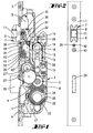
- the espagnolette lock has one with a faceplate 1 connected lock housing 2.
- the faceplate 1 protrudes on both sides the lock housing 2 and overlaps an upper and lower drive rod emerging from the lock housing 2 3, 4.
- latch members not shown provided with the door frame side, also Counter-parts not shown cooperate.
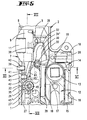
- roller trap 7 designed trap.
- the lock housing 2 In the upper area of the lock housing 2 is between a castle floor 5 and a castle ceiling 6 as Roller trap 7 designed trap.
- it is composed of a faceplate opening 8 penetrating box-shaped profile section 9, which coupled with a latch tail 10 projecting into the lock is.
- the box-shaped one is supported around a vertical axis Profile section 9 a role above this 11.
- a trap slope having trap head can be used.
- a nut housing 12 is integrated. This stores a one equipped with a square opening Lock nut 13. On a protruding nut arm 14 engages a slide 16 acted upon by a compression spring 15 on. The displacement of the lock nut 13 is limited Clockwise direction by a projection 17 of the Lock housing 12, on which projection an arm 18th the lock nut 13 supports, cf. in particular Figure 3. Furthermore, the lock nut 13 forms an upstanding Fall retraction arm 19, which with a shoulder 20th of the trap tail 10 cooperates.
- a support plate 21 is fixed on the lock base 5. This supports a ring gear 23 in a bore 22 Hole 22 is from a lock cylinder insertion opening 24 for a not illustrated, as a profile cylinder designed locking cylinder crossed.
- the cylinder core axis lies offset to the central axis of the Sprocket 23, below it.
- the ring gear 23 has a radially directed gap 25 for engaging a locking bit of the profile locking cylinder Mistake.
- the drive rod connecting slide 27 is coupled with the lower drive rod 4 while the opposite connecting rod connecting slide 28 entrains the upper drive rod 3.
- the connecting rod connecting slide 28 then still serves to drive the below the roller latch 7 guided bolt 29.
- the drive means are not essential to the invention and therefore not illustrated in detail.
- the retraction of the roller latch 7 by means of the lock cylinder actuation is possible via a change lever 30.
- the alignment of the change lever 30 runs approximately parallel to the faceplate 1.
- the change lever 30 has two arms designed and has the longer lever arm 34 and shorter lever arm 35.
- the longer lever arm 34 extends is parallel to faceplate 1 and ends at the end a step into an end section facing the lock 34 'over. This dips into a pocket trained receiving space 36 of the trap tail 10 on.
- a fixed stop 39 which in the embodiment is designed as a grub screw.
- the grub screw fixed stop 39 passes through a bore 40 of the faceplate 1 and is in an internal thread 41 of a bearing block 42 screwed in. A is used to hold it forend countersunk screw 43.
- the free end of the Set screw 39 stops against a step 44 of the longer lever arm 34.
- the shorter lever arm 35 forms an approximately perpendicular to Forend 1 extending shoulder 35 'and lies in the Path of movement of a butt edge 27 'of the led on the faceplate 1 Espagnolette connecting slide 27.
- a torsion spring 45 On the pin 33 for the change lever 30 is a torsion spring 45 inserted. One end 45 'of which is supported on a recess 46 of the bearing block 42. The other End 45 '' lies in a relaxed position in front of the shoulder 35 'of the shorter lever arm 35.
- This torsion spring 45 is used as drive rod return spring. Their travel corresponds preferably the maximum swivel path of the change lever 30th
- the retraction of the roller latch 7 can be done in a known manner on the one hand by the lock nut 13.
- the stop 38 of the catch tail 10 acts on the change lever and pivots it.
- the bolt 29 is closed from its pre-closing position by key actuation.
- the ring gear 23 is dragged clockwise.
- the connecting rod connecting slide 27 experiences an upward shift.
- the key can then be removed from the locking cylinder.
- the abutting edge 27 ' is in contact with one end 45''of the drive rod return spring 45.
- the roller trap 7 can be retracted by continuing the return rotation of the cylinder core in a clockwise direction.
- the connecting rod connecting slide 27 moves further in the upward direction and acts upon the shorter lever arm 35 of the change-over lever 30, with the end 45 ′′ of the return spring 45 being interposed, connected to a pivoting thereof.
- Its longer lever arm 34 acts on the stop 37 and pulls the latch 7 back against the force of the latch spring 31 loading it.
- the drive rod return spring 45 is charged.
- the latch spring 31 causes the latch 7 to advance, taking the change lever 30 with it. The advance of the roller latch 7 is limited when the change lever 34 acts on the grub screw fixed stop 39.
- the connecting rod return spring 45 relaxes, the movable end 45 ′′ of which pushes the connecting rod connecting slide 27 back into the basic position according to FIG.
- the ring gear is rotated via the reduction gear, taking the locking member of the locking cylinder with it, so that the key can then be removed from the locking cylinder without further locking rotation.
- the fixed stop could also be a quick adjustment enable, for example via control curves Etc..
- the spring 45 which acts on the abutting edge 27 ' has such a strength that it is under tension both the connecting rod connecting slide, as well as with it connected locking elements and the gear transmission together with the lock cylinder can push back when the cylinder is actuated stops at the change operation.
- the Torsion spring 45 is due to the small travel of their Arm 45 '' tensioned only when changing the switch.
- the change lever 30 shifted because in the intermediate position of the spring arm 45 ' Change lever arm 35 acted on the abutting edge 35 ' becomes.
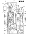
- FIG. 8-12 acts on a butt edge 27 'of the connecting rod connecting slide 27 immediately a mating edge 35 'of the lever arm 35 of the change lever 30.
- the connecting rod connecting slide return spring 45 '' is included by a cam 51, which also the rod connecting slide 27 is arranged, acted upon. there the cam 51 kicks against the end 45 "of the spring 45.
- the spring 45 is a spiral spring and on the other side in Lock housing anchored non-rotatably.
- the coil spring 45 is wrapped around a pin 33, which at the same time the Forms axis of rotation of the change lever 30.
- the connecting rod connecting slide can including the drive gear and any existing Push rod locks moved back to the neutral position if the lock operation is canceled becomes.
- a butt edge 35 ' the lever arm 35 of the change lever 30 acted upon. By pivoting the change lever 30 then retracting the trap.
- the last wheel 26 a small diameter toothing 26 ", which with correspondingly opposite toothing of the drive rods 27, 28 cooperates so that by rotating the Gear 26, the two drive rods 27, 28 in the opposite direction be relocated.
- the last wheel 26 has a larger diameter Toothing on.
- This toothing meshes with a toothing of an upstream drive wheel.
- the toothing with a larger diameter has a peripheral region 26 ', which is not toothed.
- the location of the toothless Area 26 ' is selected so that when actuated the espagnolette lock, especially the toothed drive it is ensured that the drive gear of the upstream gear always in the toothed area of the last wheel intervenes. But it provided that at a drive rod displacement from that shown in Figure 8 Neutral position in that shown in Figure 11 Locking position of the cam 51 of the connecting rod connecting slide 27 through the toothless area 26 'of the last wheel 26 dives.
- the connecting rod connecting slide 26 runs in the exemplary embodiment immediately adjacent to the cuff 1.
- the toothed area of the last wheel 26 with larger diameter but has such a diameter that it Espagnolette connecting slide protrudes and almost up to protrudes immediately in front of the cuff 1.
- the diameter advantageously corresponds to Larger toothing of the last wheel 26 approximately the distance between cuff 1 and handle housing 12 or Nut 13.
Landscapes
- Engineering & Computer Science (AREA)
- Structural Engineering (AREA)
- Mechanical Engineering (AREA)
- Lock And Its Accessories (AREA)
- Mechanical Control Devices (AREA)
- Orthopedics, Nursing, And Contraception (AREA)
Description
Die Erfindung betrifft ein Treibstangenschloß
gemäß dem Oberbegriff des
Anspruchs 1. Bei solchen
Konstruktionen handelt es
sich normaler weise um ein Schloß
mit einem
Untersetzungsgetriebe, einem schließgetriebebetätigbaren,
parallel zum Stulp verlagerbaren Treibstangenanschlußschieber
und einer zufolge eines von einem dem
Treibstangenanschlußschieber zugeordneten Anschlag beaufschlagbaren
Wechselhebels quer zum Stulp rückschließbaren
Falle.The invention relates to an espagnolette lock
according to the preamble of
Ein Treibstangenschloß der in Rede stehenden Art ist bekannt aus der DE 29 11 647 A1, wobei der Treibstangenanschlußschieber oberhalb der Falle einen den Anschlag ausbildenden Stift trägt. Dieser wirkt zusammen mit einem schloßgehäuseseitig gelagerten, doppelarmigen Wechselhebel. Dessen längerer Hebelarm greift an einem Zapfenvorsprung des Fallenschwanzes an. Bei der Wechselbetätigung erfolgt die Treibstangenrückverlagerung manuell, allenfalls unterstützt durch die Fallenfeder.An espagnolette lock of the type in question is known from DE 29 11 647 A1, the connecting rod connecting slide the stop above the trap training pen carries. This works together with a double-armed on the lock housing side Change lever. Its longer lever arm grips one Pin projection of the trap tail. When changing operation the drive rod is moved back manually, if necessary supported by the latch spring.
Dem Gegenstand der Erfindung liegt die Aufgabe zugrunde, bei einem gattungsgemäßen Treibstangenschloß die Wechselfunktion zu verbessern.The object of the invention is based on the object with a generic espagnolette lock, the changing function to improve.
Gelöst wird diese Aufgabe bei einem gattungsgemäßen Treibstangenschloß dadurch, daß eine Treibstangen-Rückdrückfeder, welche von einer dem Treibstangenanschlußschieber zugeordneten Anschlagfläche bei Wechselbetätigung gespannt wird. Die Elastizität dieser Treibstangenanschlußschieber-Rückdrückfeder reicht aus, um den Treibstangenanschlußschieber und ggf. vorhandene Treibstangenverschlüsse selbstständig in die neutrale Stellung zurückzuverlagern. Diese Anschlagfläche kann dabei von einer Stoßkante des Anschlußschiebers ausgebildet sein. Dabei kann die Feder auch das Übertragungsmittel sein, um die Teibstangenanschlußschieberverlagerung auf den Wechselhebel zu übertragen. Die Feder kann dabei in Zwischenlage zwischen Stoßkante und Wechselhebel liegen. Eine andere Realisierungsmöglichkeit dieses Gedankens besteht darin, daß der Anschlußschieber den Wechselhebel unmittelbar beaufschlagt. Dann kann auf dem Treibstangenanschlußschieber ein Nocken oder eine separate Stufe vorgesehen sein, welche die Anschlagfläche ausbildet, die die Treibstangen-Rückdrückfeder beaufschlagt. Ein Vorteil dieser Ausgestaltung liegt darin, daß bei Treibstangenanschlußschieber-Verlagerung von einer Neutralstellung in eine Riegelstellung die Treibstangenanschlußschieber-Rückdrückfeder überhaupt nicht in Wirkung zu treten braucht. Erst wenn mit dem Treibstangenanschlußschieber die Wechselbetätigung erfolgt, so daß die Falle zurückgezogen wird, wird diese Feder gespannt. Dies hat zur Folge, daß hier durch die Fallenfeder entlastet wird. Die Fallenfeder braucht dann nicht den Treibstangenanschlußschieber in die Neutralstellung zurückzuverlagern. Lediglich Wechselhebel und Falle selbst werden von der Fallenfeder in die vorgeschlossene Stellung zurückverlagert. Diese Ausbildung ist bevorzugt für Schlösser mit einer Rollenfalle, da hierdurch ein besonders günstiges und keine großen Kräfte bedürfendes Rückschließen der Falle durch Auflaufen an einem Schließblech gewährleistet ist. Bei der überführung des Treibstangenschlosses von seiner Neutralstellung in die Riegelstellung, bei welcher auch ein Schubriegel ausfahren kann, wird der Treibstangenanschlußschieber durch ein Zahnradgetriebe verlagert. Um eine besonders baugünstige Form des Schlosses zu erzielen, sind zwei gegenläufig verlagerbare Treibstangenanschlußschieber vorgesehen, von denen einer entlang der Stulpe verläuft. Das in eine Verzahnung der Treibstangenanschlußschieber eingreifende Zahnrad des Letztrades weist eine durchmessergrößere Verzahnung auf, wobei die durchmessergrößere Verzahnung im wesentlichen bis an die Stulpe heranreicht, so daß von dieser durchmessergrößeren Verzahnung der Treibstangenanschlußschieber überdeckt wird. Um eine günstige Nockenführung zu erreichen, taucht beim Verlagern des Treibstangenanschlußschiebers der Nocken durch einen zahnfreien Bereich der durchmessergrößeren Verzahnung des Letztrades. Hierdurch ist ein maximaler Durchmesser der größeren Verzahnung des Letztrades gegeben bei minimaler Baubreite des Schlosses.This task is solved with a generic Espagnolette lock in that an espagnolette return spring, which one of the connecting rod connecting slide assigned stop surface when changing operation is excited. The elasticity of this drive rod connecting slide return spring is sufficient to the connecting rod slide and any existing drive rod closures to independently return to the neutral position. This stop surface can be from an abutting edge of the connecting slide. The spring can also be the transmission medium around the Teibstangenanschlusschliebung on the Transfer lever. The spring can be in Lay the intermediate layer between the edge and the change lever. Another way of realizing this idea is that the connecting slide the change lever immediately applied. Then on the connecting rod slide a cam or a separate step be provided, which forms the stop surface, which acts on the drive rod return spring. On The advantage of this configuration is that the displacement of the connecting rod connecting slide from a neutral position in a locking position the connecting rod connecting slide return spring not at all in effect needs to kick. Only when with the connecting rod connecting slide the change operation takes place so that the trap this spring is tensioned. this has as a result that relieved here by the trap spring becomes. The latch spring then does not need the connecting rod connecting slide move back to the neutral position. Only change lever and latch itself are from the latch spring is moved back to the pre-closed position. This training is preferred for locks with a roller trap, because this makes it a particularly affordable one and inference that does not require great strength the case is guaranteed by bumping into a striking plate is. When transferring the espagnolette lock from its neutral position to the bolt position, in which a slide bolt can also extend the connecting rod connecting slide by a gear transmission relocated. To a particularly constructive form of To achieve the lock are two oppositely displaceable Espagnolette connecting slide provided, of which one runs along the cuff. That in a gear the drive rod connecting slide engaging gear the last wheel has a larger toothing on, with the larger diameter teeth in essentially reaches up to the cuff, so that from this larger diameter toothing of the connecting rod connecting slide is covered. For a cheap cam guide to reach, dives when moving the connecting rod connecting slide the cam by a tooth-free Area of the larger toothing of the last wheel. This is a maximum diameter of the larger one Gearing of the last wheel is given with minimal Width of the castle.
Nachstehend wird ein Ausführungsbeispiel der Erfindung anhand der Zeichungen erläutert. Es zeigt
Figur 1- eine Ansicht eines erfindungsgemäß gestalteten Treibstangenschlosses bei fortgelassener Schloßdecke mit Blick auf das Schloßeingerichte, betreffend die Vorschließstellung des Riegels,
Figur 2- eine Ansicht gegen den Stulp des Treibstangenschlosses,
Figur 3- in vergrößerter Darstellung das Treibstangenschloß im Bereich der als Rollenfalle gestalteten Falle, ebenfalls die Schließstellung betreffend,
Figur 4- eine der
Figur 1 entsprechende Darstellung, wobei der Riegel zurückgeschlossen ist, Figur 5- eine der
Figur 3 entsprechende Darstellung, wobei jedoch durch Wechselhebelbetätigung über den Wechselhebel die Rollenfalle schloßeinwärts gezogen ist, Figur 6- den Schnitt nach der Linie VI-VI in
Figur 5, Figur 7- den Schnitt nach der Linie VII-VII in
Figur 5, Figur 8- ein zweites Ausführungsbeispiel der Erfindung in der Neutralstellung,
Figur 9- ein Schloß gemäß
Figur 8 in fallenseitiger Ansicht bei abgenommener Stulpschiene, Figur 10- ein Schloß gemäß
Figur 8 bei Wechselbetätigung, Figur 11- ein Schloß gemäß
Figur 8 in der Verriegelungsstellung, Figur 12- eine Ansicht gemäß
Figur 9 in Stellung gemäßFigur 11.
- Figure 1
- FIG. 2 shows a view of an espagnolette lock designed according to the invention with the lock cover removed, with a view of the lock mechanism, regarding the locking position of the bolt, FIG.
- Figure 2
- a view against the faceplate of the espagnolette lock,
- Figure 3
- in an enlarged view the espagnolette lock in the area of the case designed as a roller latch, also regarding the closed position
- Figure 4
- 2 shows a representation corresponding to FIG. 1, the bolt being closed,
- Figure 5
- 3 shows a representation corresponding to FIG. 3, the roller latch being pulled inward of the lock by the change lever actuation via the change lever,
- Figure 6
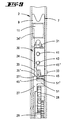
- the section along the line VI-VI in Figure 5,
- Figure 7
- the section along the line VII-VII in Figure 5,
- Figure 8
- a second embodiment of the invention in the neutral position,
- Figure 9
- 8 a lock according to FIG. 8 in a case-side view with the faceplate removed,
- Figure 10
- 8 shows a lock according to FIG.
- Figure 11
- a lock according to Figure 8 in the locking position,
- Figure 12
- 9 in the position according to FIG. 11.
Das Treibstangenschloß besitzt ein mit einem Stulp 1
verbundenes Schloßgehäuse 2. Der Stulp 1 überragt beidseitig
das Schloßgehäuse 2 und überfängt eine obere und
untere, aus dem Schloßgehäuse 2 austretende Treibstange
3, 4. Diese sind mit nicht veranschaulichten Riegelgliedern
versehen, die mit türrahmenseitigen, ebenfalls
nicht dargestellten Gegenschließteilen zusammenwirken.The espagnolette lock has one with a
Im oberen Bereich des Schloßgehäuses 2 ist zwischen
einem Schloßboden 5 und einer Schloßdecke 6 eine als
Rollenfalle 7 gestaltete Falle geführt. Im einzelnen
setzt sich diese zusammen aus einem eine Stulpöffnung 8
durchsetzenden kastenförmigen Profilabschnitt 9, welcher
mit einem schloßeinwärts ragenden Fallenschwanz 10 gekup-pelt
ist. Um eine vertikale Achse lagert der kastenförmige
Profilabschnitt 9 eine über diesen vorstehende Rolle
11. Es besteht eine Steckkupplung zwischen Fallenschwanz
10 und Profilabschnitt 9. Gegebenenfalls könnte anstelle
desselben auch ein normal gestalteter, eine Fallenschräge
aufweisender Fallenkopf eingesetzt werden.In the upper area of the
In das Schloßgehäuse 2 ist ein Nußgehäuse 12 integriert.
Dieses lagert eine mit einer Vierkantöffnung ausgestattete
Schloßnuß 13. An einem ausladenden Nußarm 14 greift
ein von einer Druckfeder 15 beaufschlagter Schieber 16
an. Begrenzt ist die Verlagerung der Schloßnuß 13 entgegen
Uhrzeigerrichtung durch einen Vorsprung 17 des
Schloßgehäuses 12, an welchem Vorsprung sich ein Arm 18
der Schloßnuß 13 abstützt, vgl. insbesondere Figur 3.
Ferner bildet die Schloßnuß 13 einen aufwärtsragenden
Fallenrückzugsarm 19 aus, welcher mit einer Schulter 20
des Fallenschwanzes 10 zusammenwirkt.In the
Am Schloßboden 5 ist eine Trägerplatte 21 festgelegt.
Diese lagert in einer Bohrung 22 einen Zahnkranz 23. Die
Bohrung 22 wird von einer Schließzylinder-Einstecköffnung
24 für einen nicht veranschaulichten, als Profilzylinder
gestalteten Schließzylinder gekreuzt. Die Zylinderkernachse
liegt dabei versetzt zur Mittelachse des
Zahnkranzes 23, und zwar unterhalb desselben.A
Der Zahnkranz 23 ist mit einem radial gerichteten Spalt
25 zum Eingriff eines Schließbartes des Profil-Schließzylinders
versehen. Mit der Außenverzahnung des Zahnkranzes
23 kämmen zwei Abtriebszahnräder A, B eines Untersetzungsgetriebes
U, dessen Letztrad 26 zum Antrieb zweier
gegenläufig verlagerbarer Treibstangenanschlußschieber
27, 28 dient. Der Treibstangenanschlußschieber 27 ist
dabei gekuppelt mit der unteren Treibstange 4, während
der gegenüberliegende Treibstangenanschlußschieber 28
die obere Treibstange 3 mitschleppt. Der Treibstangenanschlußschieber
28 dient dann noch zum Antrieb des unterhalb
der Rollenfalle 7 geführten Riegels 29. Die Antriebsmittel
sind nicht erfindungswesentlich und daher
nicht näher veranschaulicht.The
Das Zurückziehen der Rollenfalle 7 mittels Schließzylinderbetätigung
ist über einen Wechselhebel 30 möglich.
Dies geschieht entgegen der Kraft einer auf die Rollenfalle
wirkenden Fallenfeder 31. Diese sitzt auf einem
Stehzapfen 32 des Schloßgehäuses 2. Gelagert ist der
Wechselhebel 30 um einen Zapfen 33 des Schloßgehäuses 2.
Dieser erstreckt sich in Nachbarschaft des Stulps 1,
unterhalb der Rollenfalle 7 und oberhalb des Letztrades
26. Die Ausrichtung des Wechselhebels 30 verläuft etwa
parallel zum Stulp 1. Der Wechselhebel 30 ist zweiarmig
gestaltet und besitzt den längeren Hebelarm 34 und den
kürzeren Hebelarm 35. Der längere Hebelarm 34 erstreckt
sich dabei parallel zum Stulp 1 und geht endseitig über
eine Stufe in einen schloßeinwärts weisenden Endabschnitt
34' über. Dieser taucht in einen als Tasche
ausgebildeten Aufnahmefreiraum 36 des Fallenschwanzes 10
ein. Durch den Aufnahmefreiraum 36 werden zwei gegenüberliegende
Anschläge 37, 38 gebildet. Bei vorgetretener
Falle 7, hervorgerufen durch die Fallenfeder 31, beaufschlagt
der Anschlag 37 den Endabschnitt 34' des Wechselhebels
30. Seinerseits ist der Wechselhebel 34 abgestützt
durch einen Festanschlag 39, welcher beim Ausführungsbeispiel
als Madenschraube gestaltet ist. Der Madenschrauben-Festanschlag
39 durchgreift eine Bohrung 40
des Stulps 1 und ist in ein Innengewinde 41 eines Lagerbockes
42 eingedreht. Zu dessen Halterung dient eine
stulpseitige Senkkopfschraube 43. Das freie Ende des
Madenschrauben-Festanschlages 39 tritt gegen eine Stufe
44 des längeren Hebelarmes 34.The retraction of the
Der kürzere Hebelarm 35 bildet eine etwa senkrecht zum
Stulp 1 verlaufende Schulter 35' aus und liegt in der
Bewegungsbahn einer Stoßkante 27' des am Stulp 1 geführten
Treibstangenanschlußschiebers 27.The
Auf den Zapfen 33 für den Wechselhebel 30 ist eine Drehfeder
45 gesteckt. Deren eines Ende 45' stützt sich ab
an einer Aussparung 46 des Lagerbockes 42. Das andere
Ende 45'' liegt in entspannter Stellung vor der Schulter
35' des kürzeren Hebelarmes 35. Diese Drehfeder 45 dient
als Treibstangenrückdrückfeder. Deren Federweg entspricht
bevorzugt dem maximalen Schwenkweg des Wechselhebels
30.On the
Ferner ist ein Hebelverhältnis von 1:10 zwischen dem
kürzeren Hebelarm 35 und dem längeren Hebelarm 34 vorgesehen.
Bei einem Verlagerungsweg des Treibstangenanschlußschiebers
27 um 1 bis 1,3 mm zieht der Wechselhebel
30 die Falle 7 um ca. 10 mm zurück.Furthermore, a leverage ratio of 1:10 between the
Es stellt sich folgende Wirkungsweise ein:
Das Zurückziehen der Rollenfalle 7 kann in bekannter
Weise einerseits durch die Schloßnuß 13 geschehen. Nach
Durchlauf eines entsprechenden Spiels beaufschlagt dabei
der Anschlag 38 des Fallenschwanzes 10 den Wechselhebel
und verschwenkt diesen. Das Zurückschließen des Riegels
29 aus seiner Vorschließstellung geschieht durch Schlüsselbetätigung.
Dabei wird der Zahnkranz 23 in Uhrzeigerrichtung
mitgeschleppt. Über das Letztrad 26 des Untersetzungsgetriebes
U erfährt der Treibstangenanschlußschieber
27 eine Aufwärtsverlagerung. In der Rückschließstellung
gemäß Figur 3 läßt sich sodann der Schlüssel
aus dem Schließzylinder abziehen. Dann befindet sich die
Stoßkante 27' in Anlage an dem einen Ende 45'' der Treibstangenrückdrückfeder
45. Aus dieser Stellung heraus
läßt sich durch Fortsetzen der Rückschließdrehung des
Zylinderkerns in Uhrzeigerrichtung die Rollenfalle 7
zurückziehen. Hierbei fährt der Treibstangenanschlußschieber
27 weiter in Aufwärtsrichtung und beaufschlagt
unter Zwischenlage des Endes 45'' der Rückdrückfeder 45
den kürzeren Hebelarm 35 des Wechselhebels 30, verbunden
mit einem Verschwenken desselben. Dessen längerer Hebelarm
34 beaufschlagt den Anschlag 37 und zieht die Falle
7 entgegen der Kraft der sie belastenden Fallenfeder 31
zurück. Bei diesem Vorgang wird die Treibstangenrückdrückfeder
45 aufgeladen. Nach Beenden der Schließdrehung
bewirkt die Fallenfeder 31 ein Vortreten der Falle
7 unter Mitnahme des Wechselhebels 30. Begrenzt ist der
Vortritt der Rollenfalle 7, wenn der Wechselhebel 34 den
Madenschrauben-Festanschlag 39 beaufschlagt. Gleichzeitig
mit diesem Vorgang entspannt sich die Treibstangenrückdrückfeder
45, deren bewegliches Ende 45'' den Treibstangenanschlußschieber
27 in die Grundstellung gemäß
Figur 4 zurückverlagert. Einhergehend mit dessen Bewegung
wird der Zahnkranz über das Untersetzungsgetriebe
gedreht unter Mitnahme des Schließgliedes des Schließzylinders,
so daß dann der Schlüssel aus dem Schließzylinder
ohne weitere Schließdrehung abziehbar ist.The following mode of action occurs:
The retraction of the
Soll die Vortrittsstellung der Rollenfalle geändert werden, so ist dies möglich durch weiteres Hineindrehen oder Herausdrehen des Madenschrauben-Festanschlages von der Stulpseite her.Should change the leading position of the roller trap this is possible by turning it in further or unscrew the grub screw fixed stop from the cuff side.
Gegebenenfalls könnte der Festanschlag auch eine Schnellverstellung ermöglichen, beispielsweise über Steuerkurven etc.. If necessary, the fixed stop could also be a quick adjustment enable, for example via control curves Etc..
Die Feder 45, welche von der Stoßkante 27' beaufschlagt
wird, hat eine derartige Stärke, daß sie bei Spannung
sowohl den Treibstangenanschlußschieber, als auch damit
verbundene Verriegelungselemente und das Zahnradgetriebe
nebst Schließzylinder zurückdrücken kann, wenn die Zylinderbetätigung
bei der Wechselbetätigung aufhört. Die
Drehfeder 45 wird zufolge des geringen Federweges ihres
Armes 45'' nur bei der Wechselbetätigung gespannt. Beim
Übergang von der Neutralstellung (Figur 4) in die Wechselbestätigungsstellung
(Figur 5) wird die Feder von der
Stoßkante 27' an dem Federarm 45'' beaufschlagt, und
gespannt. Einhergehend damit wird der Wechselhebel 30
verlagert, da in der Zwischenlage des Federarmes 45' der
Wechselhebelarm 35 an der Stoßkante 35' beaufschlagt
wird.The
Bei dem in den Figuren 8 - 12 dargestellten Ausführungsbeispiel
beaufschlagt eine Stoßkante 27' des Treibstangenanschlußschiebers
27 unmittelbar eine Gegenstoßkante
35' des Hebelarmes 35 des Wechselhebels 30. Die Treibstangenanschlußschieber-Rückdrückfeder
45'' wird dabei
von einem Nocken 51, welche auch dem Triebstangenanschlußschieber
27 angeordnet ist, beaufschlagt. Dabei
tritt der Nocken 51 gegen das Ende 45 " der Feder 45.
Die Feder 45 ist eine Spiralfeder und anderendseitig im
Schloßgehäuse drehfest verankert. Die Spiralfeder 45 ist
um einen Zapfen 33 gewickelt, welcher gleichzeitig die
Drehachse des Wechselhebels 30 ausbildet. Wie insbesondere
aus Figur 8 hervorgeht, ist in der Neutralstellung,
also bei unbetätigtem Wechselhebel 30 und unbetätigtem
Riegel 29, die Treibstangenanschlußschieber-Rückdrückfeder
45 nicht gespannt. Erst wenn der Treibstangenanschlußschieber
27 zufolge Schloßbetätigung in der Darstellung
nach oben verlagert wird, verlagert der Nocken
51 durch Beaufschlagung des Endes 45 " die Feder 45. In the embodiment shown in Figures 8-12
acts on a
Zufolge dieser Spannung kann der Treibstangenanschlußschieber
inkl. des Antriebsgetriebes und ggf. vorhandener
Treibstangenverschlüsse in die Neutralstellung zurückverlagert
werden, wenn die Schloßbetätigung abgebrochen
wird. Einhergehend mit der Treibstangenverlagerung
in die Stellung gemäß Figur 10 wird eine Stoßkante 35'
des Hebelarmes 35 des Wechselhebels 30 beaufschlagt.
Durch die Verschwenkung des Wechselhebels 30 erfolgt
dann das Zurückziehen der Falle.As a result of this voltage, the connecting rod connecting slide can
including the drive gear and any existing
Push rod locks moved back to the neutral position
if the lock operation is canceled
becomes. Along with the drive rod displacement
in the position according to FIG. 10, a
Wie den Figuren zu entnehmen ist, weist das Letztrad 26
eine durchmesserkleine Verzahnung 26 " auf, welche mit
entsprechend gegenüberliegenden Verzahnungen der Treibstangen
27, 28 zusammenwirkt, so daß durch Drehung des
Zahnrades 26 die beiden Treibstangen 27, 28 in Gegenrichtung
verlagert werden. Axial zur Drehachse des Letztrades
26 beabstandet, weist das Letztrad 26 eine durchmessergrößere
Verzahnung auf. Diese Verzahnung kämmt mit
einer Verzahnung eines vorgeordneten Antriebsrades. Die
durchmessergrößere Verzahnung weist einen Umfangsbereich
26' auf, welcher nicht verzahnt ist. Die Lage des zahnfreien
Bereichs 26' ist so gewählt, daß bei Betätigung
des Treibstangenschlosses, insbesondere des Zahnantriebes
sichergestellt ist, daß das Antriebszahnrad des
vorgeordneten Zahnrades immer in den verzahnten Bereich
des Letztrades eingreift. Es aber vorgesehen, daß bei
einer Treibstangenverlagerung von der in Figur 8 dargestellten
Neutralstellung in die in Figur 11 dargestellte
Riegelstellung der Nocken 51 des Treibstangenanschlußschiebers
27 durch den zahnfreien Bereichs 26' des Letztrades
26 taucht.As can be seen from the figures, the last wheel 26
a
Der Treibstangenanschlußschieber 26 läuft beim Ausführungsbeispiel
unmittelbar benachbart zur Stulpe 1. Der
verzahnte durchmessergrößere Bereich des Letztrades 26
weist aber einen derartigen Durchmesser auf, daß er den
Treibstangenanschlußschieber überragt und nahezu bis
unmittelbar vor die Stulpe 1 ragt.The connecting
Es ist festzustellen, daß beim Ausführungsbeispiel der
Erfindung zur Verlagerung des Treibstangenanschlußschiebers
von der Verriegelungsstellung (Figur 11) über die
Neutralstellung (Figur 8) hinaus in die Wechselbetätigungsstellung
(Figur 10) das Letztrad 26 keine 360°-Drehung
vollführt. Die Drehung des Letztrades 26 ist vielmehr
um den nicht verzahnten Winkelabschnitt verringert.It should be noted that in the embodiment of the
Invention for the displacement of the connecting rod connecting slide
from the locking position (Figure 11) on the
Neutral position (Figure 8) in the change actuation position
(Figure 10) the
In vorteilhafter Weise entspricht der Durchmesser der
durchmessergrößeren Verzahnung des Letztrades 26 in etwa
dem Abstand zwischen Stulpe 1 und Drückergehäuse 12 bzw.
Drückernuß 13.The diameter advantageously corresponds to
Larger toothing of the
Claims (9)
- Driving rod lock or closure with a gear-driven driving rod connecting slide (27) displaceable out of a first position corresponding to a release position into a second position corresponding to a locking position, with a catch (7) which can be subjected to alternating actuation by a lock cylinder or the like against the return force of a catch spring (31), wherein an alternating lever (30) is actuatable together with the driving rod connecting slide (27) which is displaceable beyond the first position into a third position corresponding to an alternating actuating position, characterised by a driving rod return spring (45) which engages a stop face (27', 51') of the driving rod connecting slide and is different from the catch spring (31) and which is tensioned upon changing from the first to the third position and whose elasticity is sufficient to displace the driving rod connecting slide (27, 28) and if occasion arises driving rod closures independently back into the first position.
- Driving rod lock or closure according to claim 1, characterised by two driving rod connecting slides (27, 28) which are displaceable in opposite directions and which are driven by a last gear (26) of a gear mechanism which with its driven tooth system engages in a tooth system of the driving rod connecting slide (27, 28).
- Driving rod lock or closure according to any of the preceding claims, characterised in that the driving rod connecting slide (27) runs immediately adjacent to the cuff plate (1).
- Driving rod lock or closure according to any of the preceding claims, characterised in that the driving rod connecting slide return spring (45) engages a cam (51) of the driving rod connecting slide (27).
- Driving rod lock or closure according to claim 4, characterised in that the cam (51) passes through a tooth-free region (26') of the driven tooth system of the last gear (26), in particular upon changing from the first to the second position.
- Driving rod lock or closure according to any of the preceding claims, characterised in that the diameter of the driven tooth system of the last gear (26) roughly corresponds to the distance between latch nut (13) or latch nut housing (12) and cuff plate (1).
- Driving rod lock or closure according to any of the preceding claims, characterised in that the stop face (27') acts upon the alternating lever (30) with the interposition of the driving rod return spring (45), wherein the spring path of the driving rod return spring (45) preferably corresponds to the maximum pivot path of the alternating lever (30).
- Driving rod lock or closure according to any of the preceding claims, characterised in that the transmission ratio of the alternating arms (35, 34) is 1:10, wherein preferably a displacement path of the driving rod connecting slide through 1 to 1.3 mm is accompanied by a catch closure path of 10 mm.
- Driving rod lock or closure according to any of the preceding claims, characterised in that the driving rod return spring (45) is tensioned only in the alternating function.
Applications Claiming Priority (5)
| Application Number | Priority Date | Filing Date | Title |
|---|---|---|---|
| DE4322457 | 1993-07-06 | ||
| DE4322457 | 1993-07-06 | ||
| DE4405816 | 1994-02-23 | ||
| DE4405816A DE4405816C2 (en) | 1993-07-06 | 1994-02-23 | Rod lock |
| EP94105749A EP0633379B1 (en) | 1993-07-06 | 1994-04-14 | Espagnolette |
Related Parent Applications (2)
| Application Number | Title | Priority Date | Filing Date |
|---|---|---|---|
| EP94105749.9 Division | 1994-04-14 | ||
| EP94105749A Division EP0633379B1 (en) | 1993-07-06 | 1994-04-14 | Espagnolette |
Publications (3)
| Publication Number | Publication Date |
|---|---|
| EP0806534A2 EP0806534A2 (en) | 1997-11-12 |
| EP0806534A3 EP0806534A3 (en) | 1998-03-11 |
| EP0806534B1 true EP0806534B1 (en) | 2003-06-04 |
Family
ID=6492078
Family Applications (1)
| Application Number | Title | Priority Date | Filing Date |
|---|---|---|---|
| EP97113389A Expired - Lifetime EP0806534B1 (en) | 1993-07-06 | 1994-04-14 | Espagnolette |
Country Status (2)
| Country | Link |
|---|---|
| EP (1) | EP0806534B1 (en) |
| DE (3) | DE4405816C2 (en) |
Families Citing this family (3)
| Publication number | Priority date | Publication date | Assignee | Title |
|---|---|---|---|---|
| DE29722665U1 (en) * | 1997-12-22 | 1998-03-05 | Hoppe Holding AG, Müstair | Drive for the actuation of functional elements |
| DE10243890B3 (en) * | 2002-09-21 | 2004-05-27 | Carl Fuhr Gmbh & Co. Kg | Rod lock |
| AT510092B1 (en) * | 2010-07-07 | 2012-04-15 | Roto Frank Ag | LOCK |
Family Cites Families (4)
| Publication number | Priority date | Publication date | Assignee | Title |
|---|---|---|---|---|
| DE7908341U1 (en) * | 1979-03-24 | 1983-11-03 | Fa. Karl Fliether, 5620 Velbert | DOOR LOCK, IN PARTICULAR POCKET LOCK |
| FR2469537A1 (en) * | 1979-11-15 | 1981-05-22 | Gilro | Key-actuated multi-bolt lock external door - uses retraction latch bolt at closure to trigger partial emergence casement bolts and dead bolt |
| DE3836694C2 (en) * | 1988-10-28 | 1996-05-09 | Fliether Karl Gmbh & Co | Espagnolette lock |
| DE4014041A1 (en) * | 1990-05-02 | 1991-11-07 | Fuhr Carl Gmbh & Co | LOCKING CYLINDER ACTUATED ROD LOCK |
-
1994
- 1994-02-23 DE DE4405816A patent/DE4405816C2/en not_active Expired - Lifetime
- 1994-04-14 DE DE59407112T patent/DE59407112D1/en not_active Expired - Fee Related
- 1994-04-14 DE DE59410294T patent/DE59410294D1/en not_active Expired - Fee Related
- 1994-04-14 EP EP97113389A patent/EP0806534B1/en not_active Expired - Lifetime
Also Published As
| Publication number | Publication date |
|---|---|
| DE4405816A1 (en) | 1995-01-19 |
| DE59410294D1 (en) | 2003-07-10 |
| DE59407112D1 (en) | 1998-11-26 |
| EP0806534A3 (en) | 1998-03-11 |
| EP0806534A2 (en) | 1997-11-12 |
| DE4405816C2 (en) | 2002-11-21 |
Similar Documents
| Publication | Publication Date | Title |
|---|---|---|
| DE3447748C2 (en) | ||
| DE3605826A1 (en) | Espagnolette fastening with handle return | |
| DE3505379C1 (en) | Espagnolette lock | |
| DE69808030T2 (en) | Espagnolette lock for a door, French door or the like | |
| EP0168001B1 (en) | Espagnolette lock | |
| EP0907815A1 (en) | Closure for doors, bonnets, tailgates or the like, in particular of vehicles, such as motor vehicles | |
| EP0954667B1 (en) | Lock with catch bolt for door or window | |
| EP1020594A2 (en) | Espagnolette lock | |
| DE4014046C2 (en) | Lock cylinder actuable espagnolette lock | |
| EP1020597A1 (en) | Espagnolette lock with a main lock and an auxiliary lock | |
| EP0515922B1 (en) | Combination lock, especially for suitcase, furniture or similar | |
| EP0485767B1 (en) | Lock for the wing, especially the sliding wing, of a window, door etc. | |
| DE4114007A1 (en) | Main rod lock operated by pushbutton - incorporates stop component preventing drive unit moving from closed to open positions | |
| DE3148030A1 (en) | Gearwheel drive in an espagnolette lock actuable by lock cylinder and having a push bolt | |
| EP0806534B1 (en) | Espagnolette | |
| DE3520861A1 (en) | Push-back stop on espagnolette fittings, especially key-actuable espagnolette locks | |
| EP0581338B1 (en) | Plug actuated sliding bar lock | |
| DE69800295T2 (en) | Espagnolette fitting or espagnolette lock for door, window or the like. | |
| EP1672153B1 (en) | Lock with dead bolt and dead bolt actuating device | |
| DE3427713A1 (en) | Espagnolette lock with multi-turn closing | |
| EP0454960B1 (en) | Espagnolette | |
| AT394607B (en) | MULTIPLE LOCKING | |
| EP0496076B1 (en) | Espagnolette lock | |
| EP0974721B1 (en) | Lock with several bolts | |
| EP0633379B1 (en) | Espagnolette |
Legal Events
| Date | Code | Title | Description |
|---|---|---|---|
| PUAI | Public reference made under article 153(3) epc to a published international application that has entered the european phase |
Free format text: ORIGINAL CODE: 0009012 |
|
| AC | Divisional application: reference to earlier application |
Ref document number: 633379 Country of ref document: EP |
|
| AK | Designated contracting states |
Kind code of ref document: A2 Designated state(s): AT DE FR GB IT |
|
| PUAL | Search report despatched |
Free format text: ORIGINAL CODE: 0009013 |
|
| AK | Designated contracting states |
Kind code of ref document: A3 Designated state(s): AT DE FR GB IT |
|
| 17P | Request for examination filed |
Effective date: 19980522 |
|
| 17Q | First examination report despatched |
Effective date: 20000105 |
|
| GRAH | Despatch of communication of intention to grant a patent |
Free format text: ORIGINAL CODE: EPIDOS IGRA |
|
| GRAH | Despatch of communication of intention to grant a patent |
Free format text: ORIGINAL CODE: EPIDOS IGRA |
|
| GRAA | (expected) grant |
Free format text: ORIGINAL CODE: 0009210 |
|
| RAP1 | Party data changed (applicant data changed or rights of an application transferred) |
Owner name: CARL FUHR GMBH & CO. KG |
|
| AC | Divisional application: reference to earlier application |
Ref document number: 0633379 Country of ref document: EP Kind code of ref document: P |
|
| AK | Designated contracting states |
Designated state(s): AT DE FR GB IT |
|
| REG | Reference to a national code |
Ref country code: GB Ref legal event code: FG4D Free format text: NOT ENGLISH |
|
| GBT | Gb: translation of ep patent filed (gb section 77(6)(a)/1977) | ||
| REF | Corresponds to: |
Ref document number: 59410294 Country of ref document: DE Date of ref document: 20030710 Kind code of ref document: P |
|
| ET | Fr: translation filed | ||
| PGFP | Annual fee paid to national office [announced via postgrant information from national office to epo] |
Ref country code: GB Payment date: 20040406 Year of fee payment: 11 |
|
| PLBE | No opposition filed within time limit |
Free format text: ORIGINAL CODE: 0009261 |
|
| STAA | Information on the status of an ep patent application or granted ep patent |
Free format text: STATUS: NO OPPOSITION FILED WITHIN TIME LIMIT |
|
| 26N | No opposition filed |
Effective date: 20040305 |
|
| PG25 | Lapsed in a contracting state [announced via postgrant information from national office to epo] |
Ref country code: GB Free format text: LAPSE BECAUSE OF NON-PAYMENT OF DUE FEES Effective date: 20050414 |
|
| GBPC | Gb: european patent ceased through non-payment of renewal fee |
Effective date: 20050414 |
|
| PGFP | Annual fee paid to national office [announced via postgrant information from national office to epo] |
Ref country code: DE Payment date: 20080403 Year of fee payment: 15 |
|
| PGFP | Annual fee paid to national office [announced via postgrant information from national office to epo] |
Ref country code: AT Payment date: 20080404 Year of fee payment: 15 |
|
| PGFP | Annual fee paid to national office [announced via postgrant information from national office to epo] |
Ref country code: IT Payment date: 20080429 Year of fee payment: 15 |
|
| PGFP | Annual fee paid to national office [announced via postgrant information from national office to epo] |
Ref country code: FR Payment date: 20080403 Year of fee payment: 15 |
|
| REG | Reference to a national code |
Ref country code: FR Ref legal event code: ST Effective date: 20091231 |
|
| PG25 | Lapsed in a contracting state [announced via postgrant information from national office to epo] |
Ref country code: DE Free format text: LAPSE BECAUSE OF NON-PAYMENT OF DUE FEES Effective date: 20091103 Ref country code: AT Free format text: LAPSE BECAUSE OF NON-PAYMENT OF DUE FEES Effective date: 20090414 |
|
| PG25 | Lapsed in a contracting state [announced via postgrant information from national office to epo] |
Ref country code: FR Free format text: LAPSE BECAUSE OF NON-PAYMENT OF DUE FEES Effective date: 20091222 |
|
| PG25 | Lapsed in a contracting state [announced via postgrant information from national office to epo] |
Ref country code: IT Free format text: LAPSE BECAUSE OF NON-PAYMENT OF DUE FEES Effective date: 20090414 |