EP1020594A2 - Espagnolette lock - Google Patents
Espagnolette lock Download PDFInfo
- Publication number
- EP1020594A2 EP1020594A2 EP00100605A EP00100605A EP1020594A2 EP 1020594 A2 EP1020594 A2 EP 1020594A2 EP 00100605 A EP00100605 A EP 00100605A EP 00100605 A EP00100605 A EP 00100605A EP 1020594 A2 EP1020594 A2 EP 1020594A2
- Authority
- EP
- European Patent Office
- Prior art keywords
- bolt
- lever part
- change lever
- trap
- additional
- Prior art date
- Legal status (The legal status is an assumption and is not a legal conclusion. Google has not performed a legal analysis and makes no representation as to the accuracy of the status listed.)
- Granted
Links
Images


Classifications
-
- E—FIXED CONSTRUCTIONS
- E05—LOCKS; KEYS; WINDOW OR DOOR FITTINGS; SAFES
- E05C—BOLTS OR FASTENING DEVICES FOR WINGS, SPECIALLY FOR DOORS OR WINDOWS
- E05C9/00—Arrangements of simultaneously actuated bolts or other securing devices at well-separated positions on the same wing
- E05C9/04—Arrangements of simultaneously actuated bolts or other securing devices at well-separated positions on the same wing with two sliding bars moved in opposite directions when fastening or unfastening
- E05C9/041—Arrangements of simultaneously actuated bolts or other securing devices at well-separated positions on the same wing with two sliding bars moved in opposite directions when fastening or unfastening with rack and pinion mechanism
-
- E—FIXED CONSTRUCTIONS
- E05—LOCKS; KEYS; WINDOW OR DOOR FITTINGS; SAFES
- E05C—BOLTS OR FASTENING DEVICES FOR WINGS, SPECIALLY FOR DOORS OR WINDOWS
- E05C9/00—Arrangements of simultaneously actuated bolts or other securing devices at well-separated positions on the same wing
- E05C9/04—Arrangements of simultaneously actuated bolts or other securing devices at well-separated positions on the same wing with two sliding bars moved in opposite directions when fastening or unfastening
- E05C9/047—Arrangements of simultaneously actuated bolts or other securing devices at well-separated positions on the same wing with two sliding bars moved in opposite directions when fastening or unfastening comprising key-operated locks, e.g. a lock cylinder to drive auxiliary deadbolts or latch bolts
-
- E—FIXED CONSTRUCTIONS
- E05—LOCKS; KEYS; WINDOW OR DOOR FITTINGS; SAFES
- E05B—LOCKS; ACCESSORIES THEREFOR; HANDCUFFS
- E05B59/00—Locks with latches separate from the lock-bolts or with a plurality of latches or lock-bolts
-
- E—FIXED CONSTRUCTIONS
- E05—LOCKS; KEYS; WINDOW OR DOOR FITTINGS; SAFES
- E05C—BOLTS OR FASTENING DEVICES FOR WINGS, SPECIALLY FOR DOORS OR WINDOWS
- E05C9/00—Arrangements of simultaneously actuated bolts or other securing devices at well-separated positions on the same wing
- E05C9/004—Faceplates ; Fixing the faceplates to the wing
-
- E—FIXED CONSTRUCTIONS
- E05—LOCKS; KEYS; WINDOW OR DOOR FITTINGS; SAFES
- E05C—BOLTS OR FASTENING DEVICES FOR WINGS, SPECIALLY FOR DOORS OR WINDOWS
- E05C9/00—Arrangements of simultaneously actuated bolts or other securing devices at well-separated positions on the same wing
- E05C9/18—Details of fastening means or of fixed retaining means for the ends of bars
- E05C9/1825—Fastening means
- E05C9/1833—Fastening means performing sliding movements
- E05C9/1841—Fastening means performing sliding movements perpendicular to actuating bar
-
- E—FIXED CONSTRUCTIONS
- E05—LOCKS; KEYS; WINDOW OR DOOR FITTINGS; SAFES
- E05C—BOLTS OR FASTENING DEVICES FOR WINGS, SPECIALLY FOR DOORS OR WINDOWS
- E05C9/00—Arrangements of simultaneously actuated bolts or other securing devices at well-separated positions on the same wing
- E05C9/18—Details of fastening means or of fixed retaining means for the ends of bars
- E05C9/1825—Fastening means
- E05C9/1875—Fastening means performing pivoting movements
Definitions
- the invention relates to an espagnolette lock a main lock with latch and latch and an additional lock and additional latch having an additional latch, by coupling with separate drive rods the additional bolt and the bolt by key actuation lockable synchronously and the additional latch and Trap synchronized by follower or change actuation are retractable.
- the object of the invention is based on the object a generic espagnolette lock technically to improve.
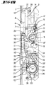
- the espagnolette lock has an elongated, rail-like faceplate 1 with the same in the central area arranged main castle 2 and on both sides the same extending additional locks 3 same Construction.
- the main lock 2 contains a trap 4, the trap head 4 'a cross-sectional opening of the cuff 1 reaches through.
- the trap tail 4 '' works together with a handle nut 6 stored in the main lock 2 the trap 4 can be moved back by alternating operation, in cooperation with a latch retraction lever 7, the underside of the follower 6 a stud 8 of the breech housing is displaceable is.
- the latch retraction lever 7 forms a concave counter shoulder 9, which with a convex Shoulder 10 of a slider 11 cooperates.
- the latter is part of one of the latch actuation Drive rod 12.
- This slide 11 is in the way a pin plug-in coupling 13 with a second, nut-controlled Slider 14 connected to which the Trap actuation associated upper drive rod 12 attacks. With the slider 11, however, is the lower Drive rod 12 coupled.
- the reduction gear 17 includes one with one Radial gap 23 equipped, stored in the lock housing Sprocket 24. This is made so that it Inserting a lock cylinder 25 in the main lock allowed.
- the closing member projects into the radial gap 23 26 of the lock cylinder 25.
- the ring gear 24 forms with one on one broadside Projection a support shoulder 27, which with the lower Interacts end 28 of a change lever part 29.
- the upper end of the change lever part 29 is in the range Shoulder 10 on the first slide 11 by means of a pin 30 hinged. By means of a from the first slide 11 the wart 31 pushed out is the change lever part 29 spaced from this slide 11 in the overlapped position
- the lower end 28 of the change lever part 29 forms one Control curve 32.
- the bar tail is 15 '' on one wide surface towered over by a molded-on cam 34.
- This a transverse niche 35 is assigned to the first slide 11.
- the transverse niche 35 is a run-up slope 36 upstream.
- the cam 34 acts with the change lever part 29 together, which in the corresponding Area has a slope 37.
- the slope 37 is a shoulder 38 downstream.
- the trigger nut 6 has a first, on the latch tail 4 '' attacking nut arm 6 'offset this a second nut arm 6 '' to cooperate with a driving shoulder 39 of the second slide 14.
- the drive rod assigned to the latch actuation 12 is within the additional lock 3 parallel to Forend 1 movable connecting slide 40 coupled. It forms a transverse shoulder at its upper end 41, in front of which the lever arm 42 of an angle lever 43 lies. The longer one compared to the lever arm 42, downward lever arm 44 operates together with an additional trap 45 Crossbar 46. The latter is from a compression spring 47 acted upon.
- the cross bar 46 has a control pin 48, which with a control groove 49 the Castle blanket 50 interacts.
- the tax groove 49 includes two fork soles 49 ', 49' 'different Length separated by a crossbar are.
- the control pin extends when the door is open 49 in the fork leg 49 'shorter length. By this is achieved by means of a guide projection 45 ' longitudinally slotted trap 45 in its normal trap entry position held according to FIG. 3. In the exit direction is the additional trap 45 from a trap spring 51 acted upon.
- the latch spring 51 can now take effect and the additional latch 45 in a bolt latch position pilot, at which advance the Angle lever 43, acted upon by crossbar 46, pivoted, the shorter lever arm 42 of the connecting slide 40 shifted slightly downwards. This results in the position according to FIGS. 6 and 7 on. In this, the cam 34 is aligned with the transverse niche 35 of the first slide 11.
- the closing of the bolts 15, 54 requires an opposite directional closing rotation of the closing member 26.
- the projection 33 of the connecting rod connecting slide 20 the control cam 32 of the change lever 29 acted upon, which in turn such pivoted that its lower end 28 in turn in the Path of movement of the closing member 26 or the support shoulder 27 of the ring gear 24 is located.
- Additional trap 45 engaging their trap position can be a key-related relocation of the Bars 15, 54 can not be carried out.
- the additional trap side Leading projection 45 'then lies in the path of movement of the stop edge 52 'of the second stop slide 52, cf. Fig. 3.
Abstract
Description
Die Erfindung betrifft einen Treibstangenverschluß mit einen Riegel und Falle aufweisendem Hauptschloß und einen Zusatzriegel und Zusatzfalle aufweisendem Zusatzschloß, wobei durch Kupplung mit getrennten Treibstangen der Zusatzriegel und der Riegel durch Schlüsselbetätigung synchron schließbar und die Zusatzfalle und Falle durch Drückernuß- oder Wechselbetätigung synchron zurückziehbar sind.The invention relates to an espagnolette lock a main lock with latch and latch and an additional lock and additional latch having an additional latch, by coupling with separate drive rods the additional bolt and the bolt by key actuation lockable synchronously and the additional latch and Trap synchronized by follower or change actuation are retractable.
Ein Schloß der in Rede stehenden Art ist Gegenstand einer nicht vorveröffentlichten Patentanmeldung 198 48 864.5.A lock of the type in question is the subject a unpublished patent application 198 48 864.5.
Dem Gegenstand der Erfindung liegt die Aufgabe zugrunde, einen gattungsgemäßen Treibstangenverschluß schließtechnisch zu verbessern.The object of the invention is based on the object a generic espagnolette lock technically to improve.
Diese Aufgabe ist zunächst und im wesentlichen bei
einem Treibstangenverschluß mit den Merkmalen des
Anspruchs 1 gelöst, wobei darauf abgestellt ist, daß
die der Fallenbetätigung zugeordnete Treibstange einen
Schieber ausbildet mit einem daran angelenkten Wechselhebelteil,
welches bei zurückgeschlossenem Riegel in
einer vom Schließglied beaufschlagbaren Lage liegt und
aus dieser beim Riegelvorschluß verschwenkt.This task is first and foremost
an espagnolette lock with the features of
Zufolge derartiger Ausgestaltung ist ein gattungsgemäßer Treibstangenverschluß von schließtechnisch günstigem Aufbau angegeben. Die Funktionsweise des Treibstangenverschlusses unterscheidet sich nicht von einem normalen Türschloß. Beim Zuziehen der eine Offenstellung einnehmenden Tür weichen sowohl Falle als auch Zusatzfalle schließblechgesteuert zwangsläufig aus, um anschließend in ihre Vortrittsstellung zu treten. Das Öffnen vom Türinneren her kann nun mittels Drückerbetätigung durchgeführt werden, wobei über die Nuß des Hauptschlosses sowohl die Falle des Hauptschlosses als auch die Zusatzfalle des Zusatzschlosses zurückgezogen werden. Letzteres geschieht über die der Fallenbetätigung zugeordnete Treibstange. Beim Zurückziehen der Falle und Zusatzfalle von der Türaußenseite her mittels des Schlüssels wird über das Schließglied das vom Schieber getragene Wechselhebelteil beaufschlagt, wodurch die den Schieber ausbildende Treibstange eine Verlagerung erfährt verbunden mit einem Zurückziehen der Zusatzfalle und einer Rückverlagerung der Falle des Hauptschlosses. Erfolgt bei zugezogener Tür eine Vorschließverlagerung des Riegels und Zusatzriegels, so wird das am Schieber angelenkte Wechselhebelteil aus dem Verlagerungsweg des Schließgliedes verschwenkt. Es liegt demgemäß nicht störend im Drehbereich des Schließgliedes. Erst in der Endphase des Zurückschließens des Riegels sowie Zusatzriegels steuert das am Schieber angelenkte Wechselhebelteil in die Mitnahmestellung zum Schließglied. In einfacher Weise ist erfindungsgemäß dabei so vorgegangen, daß das Wechselhebelteil von einem Nocken des Riegels aus der Mitnahmestellung verlagert wird, welcher Nocken in der Riegelvorschlußstellung sperrend vor einer Schulter des Wechselhebelteils liegt. Demgemäß dient der Nocken dazu, das Wechselhebelteil aus der Mitnahmestellung zu verlagern und danach das Wechselhebelteil in der verlagerten Stellung zu fixieren. Sodann ist erfindungsgemäß vorgesehen, daß das wechselhebelteil aus seiner Verlagerungsstellung durch einen eine Steuerkurve des Wechselhebelteils beaufschlagenden Vorsprung der der Riegelverlagerung zugeordneten Treibstange in die Mitnahmestellung zurückverlagert wird. Das bedeutet, daß beim zurückgeschlossenem Riegel das Wechselhebelteil bestimmungsgemäß in der vom Schließglied beaufschlagbaren Lage liegt. Damit die Falle bei vom Schlüssel verursachter Wechselbetätigung sicher mitgenommen wird, beaufschlagt der Schieber bei Wechselbetätigung mit einer Schulter eine Gegenschulter eines Fallenrückzugshebels. Im Detail sieht dies so aus, daß das Wechselhebelteil im Bereich der Schulter am Schieber angelenkt ist. Dies wirkt sich günstig auf das Zusammenwirken des Wechselhebelteils mit dem riegelseitigen Nocken aus. Eine reibungsarme Steuerung des Wechselhebelteils resultiert daraus, daß das Wechselhebelteil in Überlapptlage und durch eine Warze beabstandet zum Schieber liegt. Das Zusammenwirken des Nockens und des Wechselhebelteils ist dadurch begünstigt, daß der Nocken des Riegels gegen eine Schräge des Wechselhebelteils beim Riegelvorschluß läuft, so daß stets das sichere Aussteuern des Wechselhebelteils gewährleistet ist. Zur Erhöhung des Sicherheitswertes des Treibstangenverschlusses trägt die Tatsache bei, daß die Zusatzfalle von einer Fallenvortrittsstellung in eine Riegelfallenstellung nach schließblechbeaufschlagtem Rückschluß vorschließt. Herstellungstechnische Vorteile ergeben sich dadurch, daß der Schieber mittels Zapfen-Steckkupplung mit einem zweiten, nußgesteuerten Schieber verbunden ist. Die Mitnahme des Wechselhebelteils durch das Schließglied erfolgt indirekt, und zwar dadurch, daß das Wechselhebelteil von einer Stützschulter eines vom Schließglied mitgenommenen Zahnkranzes beaufschlagt wird.As a result of such a configuration is a generic one Espagnolette lock by locking technology favorable construction specified. How the Espagnolette lock does not differ from a normal door lock. When closing the open position engaging door give way to both trap and Additional latch controlled by the striking plate inevitably then step into their leading position. The Opening from the inside of the door can now be done using the handle be performed, taking over the nut of the Main lock both the trap of the main lock as well the additional latch of the additional lock has also been withdrawn become. The latter happens via the trap actuation associated drive rod. When withdrawing the Trap and additional trap from the outside of the door of the key is via the locking member that of the slide worn change lever part acts, whereby the drive rod forming the slide a displacement experiences associated with a withdrawal of the additional trap and a relocation of the latch of the main lock. If the door is closed, the door is moved forward of the bar and additional bar, so it will change lever part articulated on the slide from the displacement path the closing member is pivoted. It lies accordingly not disturbing in the range of rotation of the closing member. Only in the final phase of closing the Bar and additional bar controls this on the slide Articulated change lever part in the driving position for Closing link. In a simple manner, is according to the invention proceeded so that the change lever part of a cam of the bolt shifted from the driving position which cam in the locking position locking in front of a shoulder of the change lever part lies. Accordingly, the cam serves to change the lever part to move from the take-away position and afterwards the change lever part in the shifted position to fix. The invention then provides that the change lever part from its shift position through a control curve of the change lever part impacting projection of the bolt shift assigned drive rod moved back into the driving position becomes. That means that with the closed Lock the change lever part as intended the position acted upon by the closing member. So the trap when changing the key is taken safely, the Slider with one shoulder when changing Counter shoulder of a latch retraction lever. In detail this looks like the change lever part in the area the shoulder is hinged to the slider. This works favorable to the interaction of the change lever part with the bolt-side cam. A low-friction Control of the change lever part results from that the change lever part in the overlapped position and through a wart is spaced from the slide. The interaction of the cam and the change lever part favored in that the cam of the bolt against a slant of the change lever part when locking latch runs, so that the safe control of the change lever part is guaranteed. To increase the security value of the connecting rod lock carries the The fact that the additional trap from a trap entry position in a bolt latch position Closing plate-loaded conclusion. Manufacturing advantages result from that the slide by means of a plug-in coupling with a second, nut-controlled slide is connected. The Carrying the change lever part through the locking member takes place indirectly, in that the change lever part from one support shoulder to one from the locking link entrained sprocket is applied.
Nachstehend wird ein Ausführungsbeispiel der Erfindung anhand der Zeichnungen erläutert. Es zeigt
- Fig. 1
- eine Ansicht eines erfindungsgemäß gestalteten Treibstangenverschlusses mit vorgetretenen Fallen und Riegeln, betreffend die Verriegelungsstellung des Treibstangenverschlusses,
- Fig. 2
- eine klappfigürliche Darstellung der Fig. 1,
- Fig. 3
- in Einzeldarstellung das obere Zusatzschloß bei abgenommener Schloßdecke in der Stellung, die sich bei geöffneter Tür ergibt,
- Fig. 4
- in Einzeldarstellung das Hauptschloß bei fortgelassener Schloßdecke, ebenfalls bei offenstehender Tür,
- Fig. 5
- eine ausschnittsweise Vergrößerung der Fig. 4 im Riegelbereich,
- Fig. 6
- eine der Fig. 3 vergleichbare Darstellung, die sich nach dem Zuziehen der Tür ergibt,
- Fig. 7
- eine sich ebenfalls beim Zuziehen der Tür ergebende Stellung des Hauptschlosses,
- Fig. 8
- die Darstellung des Zusatzschlosses, welche sich bei Drückerverlagerung ergibt,
- Fig. 9
- das Hauptschloß bei vom Drücker verlagerter Nuß,
- Fig. 10
- das Hauptschloß in der Wechselbetätigungs-Stellung,
- Fig. 11
- das Zusatzschloß bei zugezogener Tür und vorgeschlossenem Zusatzriegel,
- Fig. 12
- das Hauptschloß bei vorgeschlossenem Riegel und
- Fig. 13
- in perspektivischer Explosionsdarstellung den ersten und zweiten Schieber mit zugeordnetem Wechselhebelteil und Fallenrückzugshebel.
- Fig. 1
- FIG. 2 shows a view of an espagnolette lock designed according to the invention with protruding latches and bolts relating to the locking position of the espagnolette lock,
- Fig. 2
- 2 shows a foldable illustration of FIG. 1,
- Fig. 3
- in individual representation, the upper additional lock with the lock cover removed in the position that results when the door is open,
- Fig. 4
- in individual representation, the main lock with the castle ceiling omitted, also with the door open,
- Fig. 5
- 4 shows a partial enlargement in the latch area,
- Fig. 6
- 3 shows a representation comparable to FIG. 3, which results after the door is closed,
- Fig. 7
- a position of the main lock that also results when the door is closed,
- Fig. 8
- the representation of the additional lock, which results when the handle is moved,
- Fig. 9
- the main lock with the nut moved by the handle,
- Fig. 10
- the main lock in the change-over position,
- Fig. 11
- the additional lock with the door closed and the additional bolt locked,
- Fig. 12
- the main lock with the bolt locked and
- Fig. 13
- in a perspective exploded view of the first and second slide with assigned change lever part and latch retraction lever.
Der Treibstangenverschluß besitzt einen langgestreckten,
schienenartigen Stulp 1 mit im Mittelbereich desselben
angeordnetem Hauptschloß 2 und sich beiderseits
desselben erstreckenden Zusatzschlössern 3 gleichen
Aufbaues.The espagnolette lock has an elongated,
rail-
Das Hauptschloß 2 beinhaltet eine Falle 4, deren Fallenkopf
4' eine querschnittsangepaßte Öffnung des Stulpes
1 durchgreift. An dem Fallenschwanz 4'' greift eine
die Falle 4 in Ausschlußrichtung beauf schlagende Fallenfeder
5 an. Der Fallenschwanz 4'' wirkt zusammen mit
einer im Hauptschloß 2 gelagerten Drückernuß 6. Ferner
ist die Falle 4 durch Wechselbetätigung zurückverlagerbar,
und zwar im Zusammenwirken mit einem Fallenrückzugshebel
7, welcher unterseitig der Drückernuß 6 um
einen Stehzapfen 8 des Verschlußgehäuses verlagerbar
ist. Hierzu bildet der Fallenrückzugshebel 7 eine
konkave Gegenschulter 9 aus, welche mit einer konvexen
Schulter 10 eines Schiebers 11 zusammenwirkt. Letzterer
ist Bestandteil einer der Fallenbetätigung zugeordneten
Treibstange 12. Dieser Schieber 11 ist im Wege
einer Zapfen-Steckkupplung 13 mit einem zweiten, nußgesteuerten
Schieber 14 verbunden, an welchem die der
Fallenbetätigung zugeordnete obere Treibstange 12 angreift.
Mit dem Schieber 11 ist dagegen die untere
Treibstange 12 gekuppelt.The
Unterhalb der Falle 4 ist im Hauptschloß 2 ein quer zum
Stulp 1 verlagerbarer Riegel 15 geführt. Dessen Riegelkopf
15' durchgreift den Stulp 1, während der Riegelschwanz
15'' an seiner Oberkante eine Zahnleiste 16
ausbildet. Diese kämmt mit einem nicht näher bezeichneten
Zahnrad eines Untersetzungsgetriebes 17, dessen
Letztrad 18 mit einer Zahnleiste 19 eines parallel zum
Stulp 1 verlagerbaren Treibstangen-Anschlußschiebers 20
kämmt. Letzterer erstreckt sich unterhalb der beiden
Schieber 11, 14 und ist mit unterhalb der Treibstangen
12 mit der der Riegelbetätigung zugeordneten Treibstangen
21 gekuppelt. Die Treibstangen 12, 21 ergänzen
sich zu einem Querschnittsprofil, welches dem einer
normal breiten Treibstange entspricht. Rückseitig sind
die Treibstangen 12, 21 von im Querschnitt U-förmigen
Haltegliedern 22 überfangen.Below the
Das Untersetzungsgetriebe 17 beinhaltet einen mit einem
Radialspalt 23 ausgestatteten, im Schloßgehäuse gelagerten
Zahnkranz 24. Dieser ist so beschaffen, daß er das
Einsetzen eines Schließzylinders 25 in das Hauptschloß
gestattet. In den Radialspalt 23 ragt das Schließglied
26 des Schließzylinders 25 hinein. Der Zahnkranz 24
formt mit einem an seiner einen Breitseite befindlichen
Vorsprung eine Stützschulter 27, welche mit dem unteren
Ende 28 eines Wechselhebelteils 29 zusammenwirkt. Das
obere Ende des Wechselhebelteils 29 ist im Bereich der
Schulter 10 am ersten Schieber 11 mittels eines Zapfens
30 angelenkt. Mittels einer aus dem ersten Schieber 11
herausgedrückten Warze 31 liegt das Wechselhebelteil 29
in Überlapptlage beabstandet zu diesem Schieber 11.
Das untere Ende 28 des Wechselhebelteils 29 bildet eine
Steuerkurve 32. Letztere arbeitet zusammen mit einem
Vorsprung 33 der der Riegelverlagerung zugeordneten
Treibstange 21 bzw. dessen Treibstangen-Anschlußschieber
20. Bei zurückgeschlossenem Riegel 15 sorgt der
Vorsprung 33 dafür, daß das Wechselhebelteil 29 mit
seinem unteren Ende 28 im Bewegungsbereich der Stützschulter
27 des Zahnkranzes 24 liegt, vergl. Fig. 4. The
An seiner einen Breitfläche wird der Riegelschwanz 15''
von einem ihm angeformten Nocken 34 überragt. Diesem
ist eine Quernische 35 am ersten Schieber 11 zugeordnet.
Der Quernische 35 ist eine Auflaufschräge 36
vorgeordnet. Ferner wirkt der Nocken 34 mit dem Wechselhebelteil
29 zusammen, welcher im entsprechenden
Bereich eine Schräge 37 besitzt. Der Schräge 37 ist
eine Schulter 38 nachgeordnet.The bar tail is 15 '' on one wide surface
towered over by a molded-on
Die Drückernuß 6 besitzt neben einem ersten, am Fallenschwanz
4'' angreifenden Nußarm 6' winkelversetzt zu
diesem einen zweiten Nußarm 6'' zum Zusammenwirken mit
einer Mitnahmeschulter 39 des zweiten Schiebers 14.The
Mit der der Fallenbetätigung zugeordneten Treibstange
12 ist innerhalb des Zusatzschlosses 3 ein parallel zum
Stulp 1 verlagerbarer Anschlußschieber 40 gekuppelt.
Derselbe bildet an seinem oberen Ende eine Querschulter
41 aus, vor welcher der Hebelarm 42 eines Winkelhebels
43 liegt. Der gegenüber dem Hebelarm 42 länger ausgebildete,
in Abwärtsrichtung weisende Hebelarm 44 arbeitet
zusammen mit einem einer Zusatzfalle 45 einverleibten
Querriegel 46. Letzterer ist von einer Druckfeder
47 beaufschlagt. Der Querriegel 46 weist einen Steuerbolzen
48 auf, welcher mit einer Steuernut 49 der
Schloßdecke 50 zusammenwirkt. Die Steuernut 49 beinhaltet
zwei Gabelsohenkel 49', 49'' unterschiedlicher
Länge, die durch einen Quersteg voneinander getrennt
sind. Bei geöffneter Tür erstreckt sich der Steuerbolzen
49 in dem Gabelschenkel 49' kürzerer Länge. Durch
diesen wird die mittels eines Führungsvorsprunges 45'
längsschlitzgeführte Falle 45 in ihrer normalen Fallenvortrittsstellung
gemäß Fig. 3 gehalten. In Austrittsrichtung
ist die Zusatzfalle 45 von einer Fallenfeder
51 beaufschlagt. With the drive rod assigned to the
Mit der der Riegelverlagerung zugeordneten Treibstange
21 ist innerhalb des Zusatzschlosses 3 ein zweiter
Anschlußschieber 52 gekuppelt, welcher seinerseits auf
dem Schloßboden des Zusatzschlosses 3 aufliegt und dort
geführt ist. Der mit einer quergerichteten Anschlußkante
52' ausgestattete Anschlußschieber 52 trägt einen
Steuervorsprung 53, welcher einen als Hakenriegel gestalteten
Zusatzriegel 54 steuert.With the drive rod assigned to the
Es stellt sich folgende Wirkungsweise ein:The following mode of action occurs:
Wird eine mit dem erfindungsgemäß gestalteten Treibstangenverschluß
versehene Tür zugezogen, so werden hierdurch
sowohl die Falle 4 des Hauptschlosses 2 als auch
die Zusatzfalle 45 des Zusatzschlosses 3 aufgrund des
türrahmenseitigen Schließbleches 55 vorerst zurückverlagert.
In der Endphase des Zuziehens der Tür treten die
Fallen 4, 45 in Eingriffsrichtung vor. Dies sieht bei
der Zusatzfalle 45 so aus, daß in der zurückverlagerten
Stellung der Steuerbolzen 48 aus dem Bereich des Gabelschenkels
49' gelangt, woraufhin die Druckfeder 47 eine
Querverlagerung des Querriegels 46 zur Verlagerungsrichtung
der Zusatzfalle 45 erzwingt. Der Steuerbolzen 48
fährt dadurch in fluchtende Stellung zum Gabelschenkel
49'' der Steuerkurve. Es kann nun die Fallenfeder 51
wirksam werden und die Zusatzfalle 45 in eine Riegelfallenstellung
vorsteuern, bei welcher Vorverlagerung der
Winkelhebel 43, beaufschlagt vom Querriegel 46, verschwenkt,
wobei dessen kürzerer Hebelarm 42 den Anschlußschieber
40 geringfügig in Abwärtsrichtung verlagert.
Es stellt sich dadurch die Position gemäß Fig. 6 und 7
ein. In dieser fluchtet der Nocken 34 mit der Quernische
35 des ersten Schiebers 11. Will one with the inventive espagnolette lock
provided door is closed, this will
both the
Aus Fig. 8 und 9 ist das Zurückziehen der Fallen 4, 45
durch Drückerbetätigung ersichtlich. Bei einem Niederdrücken
des Drückers und der dabei erfolgenden Verlagerung
der Drückernuß 6 beaufschlagt deren erster Nußarm
6' den Fallenschwanz 4'' und zieht die Falle 4 des
Hauptschlosses 2 in Einwärtsrichtung, vergl. Fig. 9.
Einhergehend beaufschlagt der zweite Nußarm 6'' die
Mitnahmeschulter 39 des zweiten Schiebers 14 und verlagert
diesen mit der Treibstange 12 in Aufwärtsrichtung.
Die Verlagerung wird dabei auf den Anschlußschieber
40 übertragen, welcher mit seiner Querschulter 41
den Winkelhebel 43 verschwenkt. Dessen längerer Hebelarm
44 greift am Querriegel 46 an und zieht über diesen
die Zusatzfalle 45 schloßeinwärts. Über die Steuernut
49 und Steuerbolzen 48 wird dabei der Querriegel 46
entgegen der Kraft der Druckfeder 47 verlagert, so daß
der Steuerbolzen 48 auf Höhe des Gabelschenkels 49'
gelangt. Wird nun die Drückerbeaufschlagung nach Aufziehen
der Tür aufgehoben, so tritt die Zusatzfalle 45
in die Stellung gemäß Fig. 3 vor, in welcher der Steuerbolzen
48 in dem kürzeren Gabelschenkel 49' der Steuernut
49 einliegt. Gleichzeitig fährt auch die Falle 4
des Hauptschlosses 2 in ihre Grundstellung vor.8 and 9 is the retraction of the
Von der Türaußenseite ist das Zurückziehen der Fallen
4, 45 auch durch Wechselbetätigung möglich. Hierbei
wird über das Schließglied 26 der Zahnkranz 24 in Uhrzeigerrichtung
mitgenommen, welch letzterer mit seiner
Stützschulter 27 das untere Ende 28 des Wechselhebelteils
29 beaufschlagt und dieses in Aufwärtsrichtung
drückt. Über den Zapfen 30 wird der erste Schieber 11
mitgenommen, welcher mit seiner Schulter 10 die Gegenschulter
9 des Fallenrückzugshebels 7 beaufschlagt und
diesen verschwenkt. Durch den am Fallenschwanz 4''
angreifenden Fallenrückzugshebel 7 wird dadurch die
Falle 4 in die Stellung gemäß Fig. 10 zurückgezogen.
Einhergehend mit der Aufwärtsverlagerung des ersten
Schiebers 11 wird der zweite Schieber 14 und damit die
Treibstange 12 mitgenommen, die ihrerseits, wie bei der
Drückerbetätigung, die Zusatzfalle 45 zurückzieht, so
daß sich auch die Stellung des Zusatzschlosses gemäß
Fig. 8 ergibt.From the outside of the door is the retraction of the
Nach Fortfall der Wechselbetätigung stellt sich wieder
die Grundstellung von Haupt- und Zusatzschloß 2, 3
gemäß Fig. 3 und 4 ein.After the change of operation ceases, it turns up again
the basic position of the main and
Ausgehend von der Vortrittsstellung von Falle 4 und
Zusatzfalle 45 bei zugezogener Tür kann das Vorschließen
von Riegel 15 und Zusatzriegel 54 erfolgen, und
zwar durch Drehen des Schlüssels bzw. Schließgliedes 26
entgegen Uhrzeigerrichtung. Über das Untersetzungsgetriebe
17 wird der Riegel 15 vorgeschlossen. Dessen
Nocken 34 greift dabei in die Quernische 35 des ersten
Schiebers 11 ein. Gleichzeitig beaufschlagt der Nocken
34 die Schulter 38 des Wechselhebelteils 29 und verschwenkt
dieses derart, daß das untere Ende 28 des Wechselhebelteils
29 außerhalb der Bewegungsbahn der Stützschulter
27 des Zahnkranzes 24 liegt, vergl. Fig. 12.
Verbunden mit dem Vorschließen des Riegels 15 erfährt
auch der Treibstangen-Anschlußschieber 20 eine Abwärtsverlagerung,
die sich auf die zugehörige Treibstange 21
überträgt. Über den Steuervorsprung 53 wird dabei der
Zusatzriegel 54 in die Riegelstellung ausgeschwenkt.
Somit befinden sich sowohl die Fallen 4, 45 als auch
die Riegel 15, 54 in Eingriff mit dem türrahmenseitigen
Schließblech 55. Ein Zurückziehen der Fallen 4, 45
mittels des Drückers ist in dieser Geschlossenstellung
durch den in die Quernische 35 eingetretenen Nocken 34
nicht möglich. Starting from the leading position of
Das Rückschließen der Riegel 15, 54 verlangt eine entgegengesetzt
gerichtete Schließdrehung des Schließgliedes
26. Hierbei wird über den Vorsprung 33 des Treibstangen-Anschlußschiebers
20 die Steuerkurve 32 des Wechselhebels
29 beaufschlagt, welcher seinerseits derart
verschwenkt, daß sein unteres Ende 28 wiederum in der
Bewegungsbahn des Schließgliedes 26 bzw. der Stützschulter
27 des Zahnkranzes 24 liegt.The closing of the
Ein störungsfreies Vorschließen des Riegels 15 bis in
seine endgültige Vortrittsstellung ist ermöglicht durch
die Auflaufschräge 36 sowie die Schräge 37.Trouble-free closing of the
Bei ihre Fallenstellung einnehmender Zusatzfalle 45
kann eine schlüsselbedingte Vorschließverlagerung der
Riegel 15, 54 nicht durchgeführt werden. Der zusatzfallenseitige
Führungsvorsprung 45' liegt dann nämlich in
der Bewegungsbahn der Anschlagkante 52' des zweiten Anschlagschiebers
52, vgl. Fig. 3.
Alle offenbarten Merkmale sind erfindungswesentlich. In die Offenbarung der Anmeldung wird hiermit auch der Offenbarungsinhalt der zugehörigen/beigefügten Prioritätsunterlagen (Abschrift der Voranmeldung) vollinhaltlich mit einbezogen, auch zu dem Zweck, Merkmale dieser Unterlagen in Ansprüche vorliegender Anmeldung mit aufzunehmen.All the features disclosed are essential to the invention. The disclosure of the application is hereby also Disclosure content of the associated / attached priority documents (Copy of the pre-registration) in full included, also for the purpose, characteristics of this Documents in claims of the present registration with to record.
Claims (10)
Priority Applications (1)
| Application Number | Priority Date | Filing Date | Title |
|---|---|---|---|
| DK00100605T DK1020594T3 (en) | 1999-01-18 | 2000-01-13 | Propeller lock |
Applications Claiming Priority (2)
| Application Number | Priority Date | Filing Date | Title |
|---|---|---|---|
| DE19901661 | 1999-01-18 | ||
| DE19901661A DE19901661A1 (en) | 1999-01-18 | 1999-01-18 | Espagnolette lock |
Publications (3)
| Publication Number | Publication Date |
|---|---|
| EP1020594A2 true EP1020594A2 (en) | 2000-07-19 |
| EP1020594A3 EP1020594A3 (en) | 2001-03-28 |
| EP1020594B1 EP1020594B1 (en) | 2004-12-01 |
Family
ID=7894548
Family Applications (1)
| Application Number | Title | Priority Date | Filing Date |
|---|---|---|---|
| EP00100605A Expired - Lifetime EP1020594B1 (en) | 1999-01-18 | 2000-01-13 | Espagnolette lock |
Country Status (5)
| Country | Link |
|---|---|
| EP (1) | EP1020594B1 (en) |
| AT (1) | ATE283956T1 (en) |
| DE (2) | DE19901661A1 (en) |
| DK (1) | DK1020594T3 (en) |
| ES (1) | ES2228307T3 (en) |
Cited By (11)
| Publication number | Priority date | Publication date | Assignee | Title |
|---|---|---|---|---|
| FR2826683A1 (en) * | 2001-07-02 | 2003-01-03 | Talleres Escoriaza Sa | Adjuster for metal door multi-point lock comprises screw mechanism with nut, counter-nut and plastic locking washer |
| EP1514986A2 (en) * | 2003-09-09 | 2005-03-16 | Aug. Winkhaus GmbH & Co. KG | Espagnolette |
| EP1857617A2 (en) * | 2006-04-07 | 2007-11-21 | Talleres De Escoriaza, S.A. | Cogwheel lock with retention for metal frame structures |
| EP2085543A2 (en) * | 2008-01-17 | 2009-08-05 | Mayer & Co. | Lock |
| EP2072723A3 (en) * | 2007-12-20 | 2011-02-02 | KFV Karl Fliether GmbH & Co. KG | Espagnolette locking device |
| CN102677989A (en) * | 2012-05-07 | 2012-09-19 | 希美克(广州)实业有限公司 | Reversible lock-body lock-cylinder structure for reducing key idling slot |
| EP2264265A3 (en) * | 2009-06-15 | 2013-01-30 | BKS GmbH | Mortise lock |
| EP2915937A1 (en) * | 2014-03-04 | 2015-09-09 | KALE Kilit ve Kalip Sanayi A.S. | Safety lock with additional security |
| GR20150100170A (en) * | 2015-04-20 | 2016-11-30 | Κλειθροποιϊα Domus A.E.B.E. | Geared multi-point lock |
| EP2543804A3 (en) * | 2011-07-06 | 2017-07-05 | MACO Technologie GmbH | Lock |
| FR3048252A1 (en) * | 2016-02-25 | 2017-09-01 | Assa Abloy Cote Picarde | LOCK ASSEMBLY WITH INDEPENDENT ACTUATION SLINGS |
Families Citing this family (3)
| Publication number | Priority date | Publication date | Assignee | Title |
|---|---|---|---|---|
| DE10024952A1 (en) * | 2000-05-22 | 2001-11-29 | Fliether Karl Gmbh & Co | Lock driven by an electric motor |
| DE202007017958U1 (en) | 2007-12-20 | 2009-04-23 | Kfv Karl Fliether Gmbh & Co. Kg | Espagnolette lock |
| DE202007017956U1 (en) | 2007-12-20 | 2009-04-23 | Kfv Karl Fliether Gmbh & Co. Kg | Espagnolette lock |
Citations (1)
| Publication number | Priority date | Publication date | Assignee | Title |
|---|---|---|---|---|
| DE19848864A1 (en) | 1998-10-23 | 2000-04-27 | Fliether Karl Gmbh & Co | Lock, especially espagnolette lock |
Family Cites Families (6)
| Publication number | Priority date | Publication date | Assignee | Title |
|---|---|---|---|---|
| GB2185059B (en) * | 1985-11-23 | 1988-06-08 | Abt Hardware Ltd | Multiple latch mechanism |
| DE3627634A1 (en) * | 1986-08-14 | 1988-02-18 | Fuhr Carl Gmbh & Co | Latch arrangement on locks for doors or the like |
| DE4014046C2 (en) * | 1990-05-02 | 1998-12-17 | Fuhr Carl Gmbh & Co | Lock cylinder actuable espagnolette lock |
| EP0712987B2 (en) * | 1994-11-17 | 2003-05-07 | KARL FLIETHER GmbH & Co. | Lock, in particular espagnolette with bipartite handle follower |
| DE29605517U1 (en) * | 1996-03-26 | 1997-07-24 | Gretsch Unitas Gmbh | Locking device |
| DE19651609B4 (en) * | 1996-12-12 | 2007-06-21 | Karl Fliether Gmbh & Co. Kg | Lock with latch and latch |
-
1999
- 1999-01-18 DE DE19901661A patent/DE19901661A1/en not_active Withdrawn
-
2000
- 2000-01-13 EP EP00100605A patent/EP1020594B1/en not_active Expired - Lifetime
- 2000-01-13 DK DK00100605T patent/DK1020594T3/en active
- 2000-01-13 AT AT00100605T patent/ATE283956T1/en active
- 2000-01-13 ES ES00100605T patent/ES2228307T3/en not_active Expired - Lifetime
- 2000-01-13 DE DE50008787T patent/DE50008787D1/en not_active Expired - Lifetime
Patent Citations (1)
| Publication number | Priority date | Publication date | Assignee | Title |
|---|---|---|---|---|
| DE19848864A1 (en) | 1998-10-23 | 2000-04-27 | Fliether Karl Gmbh & Co | Lock, especially espagnolette lock |
Cited By (18)
| Publication number | Priority date | Publication date | Assignee | Title |
|---|---|---|---|---|
| FR2826683A1 (en) * | 2001-07-02 | 2003-01-03 | Talleres Escoriaza Sa | Adjuster for metal door multi-point lock comprises screw mechanism with nut, counter-nut and plastic locking washer |
| EP1514986A2 (en) * | 2003-09-09 | 2005-03-16 | Aug. Winkhaus GmbH & Co. KG | Espagnolette |
| EP1514986A3 (en) * | 2003-09-09 | 2007-04-11 | Aug. Winkhaus GmbH & Co. KG | Espagnolette |
| EP1857617A2 (en) * | 2006-04-07 | 2007-11-21 | Talleres De Escoriaza, S.A. | Cogwheel lock with retention for metal frame structures |
| EP1857617A3 (en) * | 2006-04-07 | 2010-05-05 | Talleres De Escoriaza, S.A. | Cogwheel lock with retention for metal frame structures |
| EP2072723A3 (en) * | 2007-12-20 | 2011-02-02 | KFV Karl Fliether GmbH & Co. KG | Espagnolette locking device |
| EP2085543A2 (en) * | 2008-01-17 | 2009-08-05 | Mayer & Co. | Lock |
| EP2085543A3 (en) * | 2008-01-17 | 2013-05-01 | MACO Technologie GmbH | Lock |
| EP2264265A3 (en) * | 2009-06-15 | 2013-01-30 | BKS GmbH | Mortise lock |
| EP2543804A3 (en) * | 2011-07-06 | 2017-07-05 | MACO Technologie GmbH | Lock |
| CN102677989A (en) * | 2012-05-07 | 2012-09-19 | 希美克(广州)实业有限公司 | Reversible lock-body lock-cylinder structure for reducing key idling slot |
| CN102677989B (en) * | 2012-05-07 | 2014-09-03 | 希美克(广州)实业有限公司 | Reversible lock-body lock-cylinder structure for reducing key idling slot |
| EP2915937A1 (en) * | 2014-03-04 | 2015-09-09 | KALE Kilit ve Kalip Sanayi A.S. | Safety lock with additional security |
| WO2015132231A1 (en) * | 2014-03-04 | 2015-09-11 | Kale Kilit Ve Kalip Sanayii A.S. | A safety lock with an additional security improvement |
| EA030409B1 (en) * | 2014-03-04 | 2018-07-31 | Кале Килит Ве Калип Санайи А.С. | Safety lock with an additional security improvement |
| GR20150100170A (en) * | 2015-04-20 | 2016-11-30 | Κλειθροποιϊα Domus A.E.B.E. | Geared multi-point lock |
| GR1009037B (en) * | 2015-04-20 | 2017-05-15 | Κλειθροποιϊα Domus A.E.B.E. | Geared multi-point lock |
| FR3048252A1 (en) * | 2016-02-25 | 2017-09-01 | Assa Abloy Cote Picarde | LOCK ASSEMBLY WITH INDEPENDENT ACTUATION SLINGS |
Also Published As
| Publication number | Publication date |
|---|---|
| ATE283956T1 (en) | 2004-12-15 |
| DK1020594T3 (en) | 2005-01-31 |
| DE19901661A1 (en) | 2000-07-27 |
| EP1020594B1 (en) | 2004-12-01 |
| DE50008787D1 (en) | 2005-01-05 |
| ES2228307T3 (en) | 2005-04-16 |
| EP1020594A3 (en) | 2001-03-28 |
Similar Documents
| Publication | Publication Date | Title |
|---|---|---|
| DE3836693C2 (en) | Espagnolette lock | |
| DE3505379C2 (en) | Espagnolette lock | |
| DE3836694C2 (en) | Espagnolette lock | |
| EP2951368A1 (en) | Panic lock | |
| EP1020594B1 (en) | Espagnolette lock | |
| EP0413177A1 (en) | Lock for driving rod | |
| EP0792987A2 (en) | Espagnolette locking device | |
| EP1020597B1 (en) | Espagnolette lock with a main lock and an auxiliary lock | |
| DE4014041A1 (en) | LOCKING CYLINDER ACTUATED ROD LOCK | |
| EP0358971B1 (en) | Espagnolet | |
| DE4014046C2 (en) | Lock cylinder actuable espagnolette lock | |
| DE2738746C3 (en) | Release device for a panic door lock with latch and bolt | |
| DE4114007A1 (en) | Main rod lock operated by pushbutton - incorporates stop component preventing drive unit moving from closed to open positions | |
| EP0454959B1 (en) | Plug actuated sliding bar lock | |
| DE19822951A1 (en) | House door lock e.g. for surgeries with spring and auxiliary bolts | |
| DE4014042A1 (en) | DRIVE ROD LOCK | |
| EP0972900B1 (en) | Espagnolette lock | |
| DE4014045C2 (en) | Mortise lock, especially espagnolette lock | |
| EP0806534B1 (en) | Espagnolette | |
| EP0990758A2 (en) | Additional lock for espagnolette | |
| DE4041537A1 (en) | DRIVE ROD LOCK | |
| EP0675250B1 (en) | Lock, in particular espagnolette or similar | |
| EP0790376B1 (en) | Espagnolette lock | |
| DE3414883A1 (en) | Espagnolette lock | |
| EP0633379B1 (en) | Espagnolette |
Legal Events
| Date | Code | Title | Description |
|---|---|---|---|
| PUAI | Public reference made under article 153(3) epc to a published international application that has entered the european phase |
Free format text: ORIGINAL CODE: 0009012 |
|
| AK | Designated contracting states |
Kind code of ref document: A2 Designated state(s): AT BE CH CY DE DK ES FI FR GB GR IE IT LI LU MC NL PT SE |
|
| AX | Request for extension of the european patent |
Free format text: AL;LT;LV;MK;RO;SI |
|
| PUAL | Search report despatched |
Free format text: ORIGINAL CODE: 0009013 |
|
| AK | Designated contracting states |
Kind code of ref document: A3 Designated state(s): AT BE CH CY DE DK ES FI FR GB GR IE IT LI LU MC NL PT SE |
|
| AX | Request for extension of the european patent |
Free format text: AL;LT;LV;MK;RO;SI |
|
| RIC1 | Information provided on ipc code assigned before grant |
Free format text: 7E 05C 9/04 A, 7E 05C 9/18 B, 7E 05C 9/02 B, 7E 05B 63/14 B |
|
| 17P | Request for examination filed |
Effective date: 20010925 |
|
| AKX | Designation fees paid |
Free format text: AT BE CH CY DE DK ES FI FR GB GR IE IT LI LU MC NL PT SE |
|
| GRAP | Despatch of communication of intention to grant a patent |
Free format text: ORIGINAL CODE: EPIDOSNIGR1 |
|
| GRAS | Grant fee paid |
Free format text: ORIGINAL CODE: EPIDOSNIGR3 |
|
| RAP1 | Party data changed (applicant data changed or rights of an application transferred) |
Owner name: KARL FLIETHER GMBH & CO. KG |
|
| GRAA | (expected) grant |
Free format text: ORIGINAL CODE: 0009210 |
|
| AK | Designated contracting states |
Kind code of ref document: B1 Designated state(s): AT BE CH CY DE DK ES FI FR GB GR IE IT LI LU MC NL PT SE |
|
| PG25 | Lapsed in a contracting state [announced via postgrant information from national office to epo] |
Ref country code: FI Free format text: LAPSE BECAUSE OF FAILURE TO SUBMIT A TRANSLATION OF THE DESCRIPTION OR TO PAY THE FEE WITHIN THE PRESCRIBED TIME-LIMIT Effective date: 20041201 |
|
| REG | Reference to a national code |
Ref country code: GB Ref legal event code: FG4D Free format text: NOT ENGLISH |
|
| REG | Reference to a national code |
Ref country code: CH Ref legal event code: EP |
|
| REG | Reference to a national code |
Ref country code: IE Ref legal event code: FG4D Free format text: GERMAN |
|
| REG | Reference to a national code |
Ref country code: CH Ref legal event code: NV Representative=s name: R. A. EGLI & CO. PATENTANWAELTE |
|
| REF | Corresponds to: |
Ref document number: 50008787 Country of ref document: DE Date of ref document: 20050105 Kind code of ref document: P |
|
| PG25 | Lapsed in a contracting state [announced via postgrant information from national office to epo] |
Ref country code: CY Free format text: LAPSE BECAUSE OF FAILURE TO SUBMIT A TRANSLATION OF THE DESCRIPTION OR TO PAY THE FEE WITHIN THE PRESCRIBED TIME-LIMIT Effective date: 20050113 |
|
| PG25 | Lapsed in a contracting state [announced via postgrant information from national office to epo] |
Ref country code: MC Free format text: LAPSE BECAUSE OF NON-PAYMENT OF DUE FEES Effective date: 20050131 |
|
| REG | Reference to a national code |
Ref country code: DK Ref legal event code: T3 |
|
| PG25 | Lapsed in a contracting state [announced via postgrant information from national office to epo] |
Ref country code: GR Free format text: LAPSE BECAUSE OF FAILURE TO SUBMIT A TRANSLATION OF THE DESCRIPTION OR TO PAY THE FEE WITHIN THE PRESCRIBED TIME-LIMIT Effective date: 20050301 Ref country code: SE Free format text: LAPSE BECAUSE OF FAILURE TO SUBMIT A TRANSLATION OF THE DESCRIPTION OR TO PAY THE FEE WITHIN THE PRESCRIBED TIME-LIMIT Effective date: 20050301 |
|
| REG | Reference to a national code |
Ref country code: ES Ref legal event code: FG2A Ref document number: 2228307 Country of ref document: ES Kind code of ref document: T3 |
|
| GBT | Gb: translation of ep patent filed (gb section 77(6)(a)/1977) |
Effective date: 20050331 |
|
| ET | Fr: translation filed | ||
| PLBE | No opposition filed within time limit |
Free format text: ORIGINAL CODE: 0009261 |
|
| STAA | Information on the status of an ep patent application or granted ep patent |
Free format text: STATUS: NO OPPOSITION FILED WITHIN TIME LIMIT |
|
| 26N | No opposition filed |
Effective date: 20050902 |
|
| PGFP | Annual fee paid to national office [announced via postgrant information from national office to epo] |
Ref country code: LU Payment date: 20070103 Year of fee payment: 8 |
|
| PG25 | Lapsed in a contracting state [announced via postgrant information from national office to epo] |
Ref country code: PT Free format text: LAPSE BECAUSE OF NON-PAYMENT OF DUE FEES Effective date: 20050501 |
|
| PGFP | Annual fee paid to national office [announced via postgrant information from national office to epo] |
Ref country code: IE Payment date: 20090126 Year of fee payment: 10 Ref country code: DK Payment date: 20090122 Year of fee payment: 10 Ref country code: ES Payment date: 20090116 Year of fee payment: 10 |
|
| PGFP | Annual fee paid to national office [announced via postgrant information from national office to epo] |
Ref country code: GB Payment date: 20090122 Year of fee payment: 10 |
|
| PG25 | Lapsed in a contracting state [announced via postgrant information from national office to epo] |
Ref country code: LU Free format text: LAPSE BECAUSE OF NON-PAYMENT OF DUE FEES Effective date: 20080113 |
|
| REG | Reference to a national code |
Ref country code: DK Ref legal event code: EBP |
|
| GBPC | Gb: european patent ceased through non-payment of renewal fee |
Effective date: 20100113 |
|
| REG | Reference to a national code |
Ref country code: IE Ref legal event code: MM4A |
|
| PG25 | Lapsed in a contracting state [announced via postgrant information from national office to epo] |
Ref country code: GB Free format text: LAPSE BECAUSE OF NON-PAYMENT OF DUE FEES Effective date: 20100113 |
|
| PG25 | Lapsed in a contracting state [announced via postgrant information from national office to epo] |
Ref country code: IE Free format text: LAPSE BECAUSE OF NON-PAYMENT OF DUE FEES Effective date: 20100113 Ref country code: DK Free format text: LAPSE BECAUSE OF NON-PAYMENT OF DUE FEES Effective date: 20100131 |
|
| REG | Reference to a national code |
Ref country code: ES Ref legal event code: FD2A Effective date: 20110224 |
|
| PGFP | Annual fee paid to national office [announced via postgrant information from national office to epo] |
Ref country code: IT Payment date: 20110121 Year of fee payment: 12 Ref country code: FR Payment date: 20110209 Year of fee payment: 12 |
|
| PG25 | Lapsed in a contracting state [announced via postgrant information from national office to epo] |
Ref country code: ES Free format text: LAPSE BECAUSE OF NON-PAYMENT OF DUE FEES Effective date: 20110223 |
|
| PG25 | Lapsed in a contracting state [announced via postgrant information from national office to epo] |
Ref country code: ES Free format text: LAPSE BECAUSE OF NON-PAYMENT OF DUE FEES Effective date: 20100114 |
|
| REG | Reference to a national code |
Ref country code: FR Ref legal event code: ST Effective date: 20120928 |
|
| PG25 | Lapsed in a contracting state [announced via postgrant information from national office to epo] |
Ref country code: IT Free format text: LAPSE BECAUSE OF NON-PAYMENT OF DUE FEES Effective date: 20120113 |
|
| PG25 | Lapsed in a contracting state [announced via postgrant information from national office to epo] |
Ref country code: FR Free format text: LAPSE BECAUSE OF NON-PAYMENT OF DUE FEES Effective date: 20120131 |
|
| PGFP | Annual fee paid to national office [announced via postgrant information from national office to epo] |
Ref country code: NL Payment date: 20160126 Year of fee payment: 17 |
|
| PGFP | Annual fee paid to national office [announced via postgrant information from national office to epo] |
Ref country code: AT Payment date: 20160125 Year of fee payment: 17 |
|
| REG | Reference to a national code |
Ref country code: DE Ref legal event code: R084 Ref document number: 50008787 Country of ref document: DE |
|
| PGFP | Annual fee paid to national office [announced via postgrant information from national office to epo] |
Ref country code: CH Payment date: 20170126 Year of fee payment: 18 Ref country code: DE Payment date: 20170131 Year of fee payment: 18 |
|
| PGFP | Annual fee paid to national office [announced via postgrant information from national office to epo] |
Ref country code: BE Payment date: 20170119 Year of fee payment: 18 |
|
| REG | Reference to a national code |
Ref country code: NL Ref legal event code: MM Effective date: 20170201 |
|
| REG | Reference to a national code |
Ref country code: AT Ref legal event code: MM01 Ref document number: 283956 Country of ref document: AT Kind code of ref document: T Effective date: 20170113 |
|
| PG25 | Lapsed in a contracting state [announced via postgrant information from national office to epo] |
Ref country code: AT Free format text: LAPSE BECAUSE OF NON-PAYMENT OF DUE FEES Effective date: 20170113 |
|
| PG25 | Lapsed in a contracting state [announced via postgrant information from national office to epo] |
Ref country code: NL Free format text: LAPSE BECAUSE OF NON-PAYMENT OF DUE FEES Effective date: 20170201 |
|
| REG | Reference to a national code |
Ref country code: DE Ref legal event code: R119 Ref document number: 50008787 Country of ref document: DE |
|
| REG | Reference to a national code |
Ref country code: CH Ref legal event code: PL |
|
| PG25 | Lapsed in a contracting state [announced via postgrant information from national office to epo] |
Ref country code: DE Free format text: LAPSE BECAUSE OF NON-PAYMENT OF DUE FEES Effective date: 20180801 |
|
| REG | Reference to a national code |
Ref country code: BE Ref legal event code: MM Effective date: 20180131 |
|
| PG25 | Lapsed in a contracting state [announced via postgrant information from national office to epo] |
Ref country code: BE Free format text: LAPSE BECAUSE OF NON-PAYMENT OF DUE FEES Effective date: 20180131 Ref country code: CH Free format text: LAPSE BECAUSE OF NON-PAYMENT OF DUE FEES Effective date: 20180131 Ref country code: LI Free format text: LAPSE BECAUSE OF NON-PAYMENT OF DUE FEES Effective date: 20180131 |