EP0790376B1 - Espagnolette lock - Google Patents
Espagnolette lock Download PDFInfo
- Publication number
- EP0790376B1 EP0790376B1 EP97101678A EP97101678A EP0790376B1 EP 0790376 B1 EP0790376 B1 EP 0790376B1 EP 97101678 A EP97101678 A EP 97101678A EP 97101678 A EP97101678 A EP 97101678A EP 0790376 B1 EP0790376 B1 EP 0790376B1
- Authority
- EP
- European Patent Office
- Prior art keywords
- lock
- locking bolt
- actuation
- main
- bolt
- Prior art date
- Legal status (The legal status is an assumption and is not a legal conclusion. Google has not performed a legal analysis and makes no representation as to the accuracy of the status listed.)
- Expired - Lifetime
Links
Images


Classifications
-
- E—FIXED CONSTRUCTIONS
- E05—LOCKS; KEYS; WINDOW OR DOOR FITTINGS; SAFES
- E05C—BOLTS OR FASTENING DEVICES FOR WINGS, SPECIALLY FOR DOORS OR WINDOWS
- E05C17/00—Devices for holding wings open; Devices for limiting opening of wings or for holding wings open by a movable member extending between frame and wing; Braking devices, stops or buffers, combined therewith
- E05C17/02—Devices for holding wings open; Devices for limiting opening of wings or for holding wings open by a movable member extending between frame and wing; Braking devices, stops or buffers, combined therewith by mechanical means
- E05C17/04—Devices for holding wings open; Devices for limiting opening of wings or for holding wings open by a movable member extending between frame and wing; Braking devices, stops or buffers, combined therewith by mechanical means with a movable bar or equivalent member extending between frame and wing
- E05C17/12—Devices for holding wings open; Devices for limiting opening of wings or for holding wings open by a movable member extending between frame and wing; Braking devices, stops or buffers, combined therewith by mechanical means with a movable bar or equivalent member extending between frame and wing consisting of a single rod
- E05C17/16—Devices for holding wings open; Devices for limiting opening of wings or for holding wings open by a movable member extending between frame and wing; Braking devices, stops or buffers, combined therewith by mechanical means with a movable bar or equivalent member extending between frame and wing consisting of a single rod pivoted only at one end and having an elongated slot
- E05C17/166—Security devices
-
- E—FIXED CONSTRUCTIONS
- E05—LOCKS; KEYS; WINDOW OR DOOR FITTINGS; SAFES
- E05C—BOLTS OR FASTENING DEVICES FOR WINGS, SPECIALLY FOR DOORS OR WINDOWS
- E05C9/00—Arrangements of simultaneously actuated bolts or other securing devices at well-separated positions on the same wing
- E05C9/18—Details of fastening means or of fixed retaining means for the ends of bars
- E05C9/1825—Fastening means
- E05C9/1833—Fastening means performing sliding movements
- E05C9/1841—Fastening means performing sliding movements perpendicular to actuating bar
Definitions
- a drive rod lock of the type in question is known from the DE 35 03 466 C2 , wherein the Vorschhogrum the locking bolt of the auxiliary lock by means of a located on the inside of the door handle. In the release position of the locking bolt is brought back when closing the locked lock of the main lock. This means that unlocking the door not only the main lock, but also the auxiliary lock is opened.
- the object of the invention is based on the object, a generic espagnolette to design so that in addition to a simplified operation of the safety value is increased.
- a generic espagnolette is created, which is characterized by a simplified operation in addition to an increased safety value.
- the simplified operation results from the fact that when locking the main latch of the main lock by means of the key accompanying the locking bolt of the auxiliary lock reaches its prelocking position. So it does not have to be a separate closing operation to precede the locking bolt of the auxiliary lock.
- This also results in the increased safety value. Namely, it can not happen that forgetfulness when vorMedic the main bolt preclusion of the locking bolt is omitted. Always after closing action of the main bolt of the closing engagement of the main bolt and locking bolt is brought about. Furthermore, the advantage is maintained that after a first return operation of the main lock only the main latch is closed back. The closing of the Sperriegels then takes place after a second Ruschteurbetuschistor the main bolt, also by key operation.
- this has the coupling latching means which hold the locking bolt in the pre-closed position, which locking position is canceled in the second remindsch perennialbet decisivist.
- the procedure is to provide a first locking finger, which holds a slider arranged on the locking bar in a first detent position, which locking finger is retracted in the first return position and releases the slide for displacement in a second detent position in which the slide, is held by a second locking finger, which is retracted in the re-closed position of the main bolt and releases the slider to cancel the locking catch.
- the Locking fingers are thus shifted sequentially to their release position.
- In the first return operation thus reaches the first locking finger in the release position to the slider, whereupon this can shift to the second locking finger.
- the displacement path of the slider is so large that the locking bar still remains in its initial position. Only at the re-closed position of the main bolt of the second locking finger is withdrawn and allows the spring-loaded slide further displaced on the locking bolt and thereby releases the locking catch. Thereafter, in the second return operation of the locking bolt arrives in its retreat position.
- the solution of the invention task can be done in a generic espagnolette in the manner to provide a drive rod controlled VorQuery of the locking bar in a detent position, from which the locking bolt is shifted back by the force of a tensioned in the preselection of recoil spring in drive rod controlled detent release.
- the locking bolt is preceded in a first espagnolette displacement in the detent position, is brought in a second espagnolette displacement in a release position and closes at a third espagnolette displacement.
- a further advantageous feature of the invention is to be seen in the fact that the slider is mitverlagert in the first Vorsch thoroughlybetuschistor by means of a locking bolt arranged entrainment lever, which is dug in the final phase of the Vorsch thoroughlybetuschistorist in a release position to the slide. Then, however, is the Slider already held by the first locking finger in position.
- the control of the locking fingers is carried out in a simple manner by a arranged on a drive rod connecting slide first projection, which rearwardly displaced the first locking finger, in particular via a rocker and by a arranged on the espagnolette slide second projection, which relocates the second locking finger in the second espagnolette.
- the locking bolt is coupled via a rack with the teeth of a nut of the auxiliary lock for manual operation of the locking bolt.
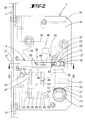
- the number 1 in Figure 1 denotes a door which is articulated by means of hinges 2 on a door frame 3.
- a drive rod lock 4 On the opposite side of the hinges 2, the door takes on a drive rod lock 4.
- the latter has a tfalz workede cuff 5 with it fixed main lock 6.
- a pawl lock additional lock 7 Above it is located on the cuff 5 designed as a pawl lock additional lock 7. That means that its locking bar 8 with a frame side hinged, longitudinally slotted locking bracket 9 cooperates.
- a pin latch lock 10 This corresponds in its construction to the bottom of the main lock 4 arranged pin lock 11th
- the main lock 4 is equipped with a latch 12 and a main latch 13. This is preferably two-speed by key operation forward and foundedsch. Along with a relocation of the Main latch 13 is displaced from the cuff 5 drive rod 14, which transfers their movement to the auxiliary lock 7 and the pin locks 10, 11.
- the additional lock 7 has a lock bottom 15 connected to the cuff 5, parallel to which a lock cover 16 extends.
- a lock cover 16 extends in the space between the lock floor and lock cover 16 in the space between the lock floor and lock cover 16 in the Schlosßeinunde. Its bolt head 8 'passes through a cross-section adapted opening 17 of the cuff 5, while the bolt tail 8' 'by means of both sides projecting pin 18 in transverse slots 19, 20 of lock bottom 15 and lock cover 16 are performed. Downwardly directed, the locking bolt tail 8 "continues into a boom 21. This forms a parallel to the direction of displacement of the locking bolt 8 extending rack 22, which cooperates with the toothing 23 of a nut 24.
- FIG. 1 illustrates an internal operating handle 27, which is suitably connected to the nut 24.
- a helically coiled return spring 33 is attached, which loads the locking bolt 8 in Sch.einfacture.
- a driving rod connecting slide 34 is guided. This is coupled to the end portions 14 'of the divided at the level of the auxiliary lock 7 drive rod 14.
- the cuff 5 facing away from the drive rod connecting slide 34 has a wedge-shaped widening wedge slot 35 into which the pin 18 is immersed. The Vorsch twice the locking bolt 8 takes place via the oblique to the direction of exclusion of the locking bolt 8 extending inclined wall 35 ', which continues at the upper end in a niche 35' '.
- the driving rod connecting slide 34 On the side facing the cuff 5, the driving rod connecting slide 34 has a recess 36, which is separated from the wedge slot 35 by a narrow longitudinal web 37. At the longitudinal web 37 is a the locking bar 8 sleeve-shaped comprehensive slider 38 is supported. A spiral spring 39 acts on the slider 38 in the direction of the longitudinal web 37.
- the lever arm 29 'of the driving lever 29 terminates at a short distance in front of the rear edge of the slider 38, cf. the starting position in Figure 3.
- the other lever arm 29 '' of the driving lever 29 acts together with a lock bottom side stop 40th
- the lock bottom 15 and the lock cover 16 facing broad side walls 38 'of the slider 38 each have a rearwardly open, extending in the longitudinal direction bolt longitudinal slot 41.
- the inner ends of the longitudinal slots 41 are formed to Aus confuseungsschrägen 42.
- Each Aus thoroughlyungsschräge 42 cooperates with the angled extending end 43 'of a leaf spring 43.
- Their width is slightly smaller than the width of the longitudinal slots 41.
- the leaf springs 43 are attached to both sides of the bar tail 8', on opposite sides of the same, see. Figure 10.
- Each leaf spring 43 carries a respective locking means 44 in the form of a locking pin. These locking means 44 dive into the longitudinal slots 41 of the slider 38 a. Due to the preload, the locking means 44 are pressed against the lock bottom 15 and lock cover 16.
- the locking means 44 cooperate with locking openings 45 in the lock bottom 15 and lock cover 16th
- the latter extends at Huaweiverlagertem locking bolt 8 between a first locking finger 47 and a second locking finger 48, which are guided transversely to the direction of movement of the locking bolt 8 in a secured to the lock bottom 15 housing 49.
- a compression spring 50 loads the rotationally secured first locking finger 47 in the direction of the locking bolt 8.
- At the upper end of the locking finger 47 forms a falling-like bevelled stop 47 'for cooperation with the locking projection 46.
- Radial directed goes from the first locking finger 47 a longitudinal slot of the housing 49 passing through driving pin 51, which cooperates with a rocker 52 mounted on the lock bottom.
- the one rocker arm 52 ' acts together with the driving pin 51, while the other rocker arm 52''according to Figure 3 is supported on a first projection 53 of the drive rod-connection slide 34.
- the protruding from the housing 49 lower end of the locking finger 47 carries a transverse pin 54, which passes through a longitudinal slot 55 of a plugged onto the lower end of the locking finger 47 shoe 56. The same passes through a slot 58 at the lower end of the locking finger 48.
- a tension spring 60 loads the trigger 59 in the counterclockwise direction such that the arm 59 'is supported on the coupling pin 57, cf. Figure 4.
- the second locking finger 48 secured in the housing 49 is loaded by a compression spring 62 in the direction of the slider 38 such that the upper end of the second locking finger 48 is supported on the underside of the slider 38, cf. in particular Figure 4.
- At the lower end of the second locking finger 48 has a projecting in the direction of the espagnolette cam cam 63 which cooperates with a arranged on the espagnolette slide 34 second projection 64.
- Figure 5 illustrates that the provided with an annular groove 8 '''bolt head 8' is engaged with the frame-side locking bracket 9, such that the locking bracket 9 and its slit at the height of the annular groove 8 '''extends.
Abstract
Description
Die Erfindung betrifft einen Treibstangenverschluß mit einem flügelseitigen, schlüsselbetätigbaren, einen Hauptriegel aufweisenden Hauptschloß, einer durch Betätigung des Hauptschlosses entlang einer Stulpe verlagerbaren Treibstange zur Betätigung eines mit einem rahmenseitigen Sperrschwenkbügel zusammenwirkenden Sperriegels eines Zusatzschlosses.The invention relates to a drive rod lock with a wing-side, key-operated, main bar having a main lock, a displaceable by actuation of the main lock along a cuff drive rod for actuating a cooperating with a frame-side Sperrschwenkbügel locking bolt of an additional lock.
Ein Treibstangenverschluß der in Rede stehenden Art ist bekannt aus der
Ferner ist es aus dem DE-GM 29 50 950 3 bekannt, den Sperriegel des Zusatzschlosses ebenfalls durch eine türinnenseitige Handhabe zu verlagern. Beim Zurückschließen des Hauptriegels des Hauptschlosses wird bei dieser Ausführungsform der Zusatzriegel noch nicht in die zurückgeschlossene Stellung bewegt, so daß der Sperriegel noch mit dem Sperrbügel in Eingriff verbleibt. Erst bei erneutem Vorschließen des Hauptriegels wird durch Treibstangenbetätigung der Sperriegel des Zusatzschlosses in die Rückschließstellung bewegt. Der Hauptriegel befindet sich dann in Eingriff. Wird dieser erneut zurückgeschlossen, läßt sich die Tür öffnen. Beiden vorgenannten Ausgestaltungen ist gemeinsam, daß das Vorschließen des Sperriegels stets gesondert von Hand durchzuführen ist.Furthermore, it is known from DE-GM 29 50 950 3, also to displace the locking bolt of the auxiliary lock by a door-side handle. When closing back the main latch of the main lock the auxiliary latch is not yet moved in the zurückgeschlossene position in this embodiment, so that the locking bar still remains in engagement with the locking bracket. Only when re-closing the main bolt is moved by espagnolette of the locking bolt of the auxiliary lock in the return position. The main bolt is then engaged. If this is closed again, the door can be opened. Both aforementioned embodiments have in common that the Vorschließ the locking bolt is always carried out separately by hand.
Dem Gegenstand der Erfindung liegt die Aufgabe zugrunde, einen gattungsgemäßen Treibstangenverschluß so auszugestalten, daß neben einer vereinfachten Bedienung der Sicherheitswert erhöht ist.The object of the invention is based on the object, a generic espagnolette to design so that in addition to a simplified operation of the safety value is increased.
Dieses technische Problem ist zunächst und im wesentlichen bei einem Treibstangenverschluß mit den Merkmalen des Anspruchs 1 gelöst, wobei darauf abgestellt ist, daß nach einer ersten Betätigung des Hauptschlosses in die Schließstellung zusammen mit dem Hauptriegel der Sperriegel des Zusatzschlosses treibstangenbetätigt vorgeschlossen ist und nach einer ersten Rückschließbetätigung des Hauptschlosses der Hauptriegel und nach einer zweiten Rückschließbetätigung der Sperriegel zurückgeschlossen sind.This technical problem is initially and essentially solved in a drive rod lock with the features of
Zufolge derartiger Ausgestaltung ist ein gattungsgemäßer Treibstangenverschluß geschaffen, der sich neben einer vereinfachten Betätigung durch einen erhöhten Sicherheitswert auszeichnet. Die vereinfachte Betätigung resultiert daraus, daß beim Vorschließen des Hauptriegels des Hauptschlosses mittels des Schlüssels einhergehend der Sperriegel des Zusatzschlosses in seine Vorschließstellung gelangt. Es hat also nicht eine gesonderte Schließbetätigung zu erfolgen, um den Sperrriegel des Zusatzschlosses vorzuschließen. Hieraus resultiert auch der erhöhte Sicherheitswert. Es kann nämlich nicht geschehen, daß aus Vergeßlichkeit beim Vorschließen des Hauptriegels das Vorschließen des Sperriegels unterbleibt. Stets ist also nach Vorschließbetätigung des Hauptriegels der Schließeingriff von Hauptriegel und Sperriegel herbeigeführt. Ferner ist der Vorteil beibehalten, daß nach einer ersten Rückschließbetätigung des Hauptschlosses nur der Hauptriegel zurückgeschlossen wird. Das Zurückschließen des Sperriegels erfolgt dann nach einer zweiten Rückschließbetätigung des Hauptriegels, und zwar ebenfalls durch Schlüsselbetätigung.According to such a design, a generic espagnolette is created, which is characterized by a simplified operation in addition to an increased safety value. The simplified operation results from the fact that when locking the main latch of the main lock by means of the key accompanying the locking bolt of the auxiliary lock reaches its prelocking position. So it does not have to be a separate closing operation to precede the locking bolt of the auxiliary lock. This also results in the increased safety value. Namely, it can not happen that forgetfulness when vorschluss the main bolt preclusion of the locking bolt is omitted. Always after closing action of the main bolt of the closing engagement of the main bolt and locking bolt is brought about. Furthermore, the advantage is maintained that after a first return operation of the main lock only the main latch is closed back. The closing of the Sperriegels then takes place after a second Rückschließbetätigung the main bolt, also by key operation.
Eine vorteilhafte Weiterbildung besteht darin, daß zwischen der ersten und zweiten Rückschließbetätigung der Hauptriegel wieder vorgeschlossen wird. Wird also nach der ersten Rückschließbetätigung der Hauptriegel wieder vorgeschlossen, befinden sich sowohl der Sperriegel als auch der Hauptriegel in der vorgeschlossenen Stellung. Beide gelangen danach gemeinsam bei der zweiten Rückschließbetätigung in die Rückschließstellung.An advantageous development is that between the first and second Rückschließbetätigung the main bolt is again vorgeschlossen. Thus, if after the first return operation of the main latch again vorgeschlossen, both the locking bolt and the main bolt are in the vorgeschlossenen position. Both then arrive together at the second return operation in the Rückschließstellung.
Damit nach dem Vorschließen des Sperriegels und Hauptriegels bei der ersten Rückschließbetätigung der Sperrriegel in seiner Vortrittsstellung verbleibt, ist eine insbesondere im Zusatzschloß angeordnete Kupplung vorgesehen, die den Sperriegel bei der ersten Vorschließbetätigung von der Schloßbetätigung entkuppelt.So that after locking the locking bolt and main bolt in the first return operation of the locking bolt remains in its forward position, a particular arranged in the additional lock clutch is provided which disengages the locking bolt in the first Vorschließbetätigung of the lock operation.
In einfacher Weise weist hierzu die Kupplung Rastmittel auf, die den Sperriegel in der vorgeschlossenen Stellung halten, welche Raststellung bei der zweiten Rückschließbetätigung aufgehoben ist.In a simple way, this has the coupling latching means which hold the locking bolt in the pre-closed position, which locking position is canceled in the second Rückschließbetätigung.
In konstruktiv einfacher Weise ist so vorgegangen, einen ersten Sperrfinger vorzusehen, der einen auf den Sperriegel angeordneten Schieber in einer ersten Raststellung hält, welcher Sperrfinger in der ersten Rückschließstellung zurückgezogen ist und den Schieber zur Verlagerung in eine zweite Raststellung freigibt, in welcher der Schieber, von einem zweiten Sperrfinger gehalten ist, der in der wieder vorgeschlossenen Stellung des Hauptriegels zurückgezogen ist und den Schieber zur Aufhebung der Sperriegelrast freigibt. Die Sperrfinger werden also nacheinander in ihre Freigabestellung verlagert. Bei der ersten Rückschließbetätigung gelangt somit der erste Sperrfinger in Freigabestellung zum Schieber, woraufhin dieser sich bis zum zweiten Rastfinger verlagern kann. Der Verlagerungsweg des Schiebers ist so groß, daß der Sperriegel noch in seiner Vortrittsstellung verbleibt. Erst bei der erneut vorgeschlossenen Stellung des Hauptriegels wird der zweite Sperrfinger zurückgezogen und erlaubt es, daß sich der Schieber federbeaufschlagt weiter auf dem Sperriegel verlagert und dabei die Sperriegelrast freigibt. Danach gelangt bei der zweiten Rückschließbetätigung der Sperriegel in seine Rücktrittsstellung.In a structurally simple manner, the procedure is to provide a first locking finger, which holds a slider arranged on the locking bar in a first detent position, which locking finger is retracted in the first return position and releases the slide for displacement in a second detent position in which the slide, is held by a second locking finger, which is retracted in the re-closed position of the main bolt and releases the slider to cancel the locking catch. The Locking fingers are thus shifted sequentially to their release position. In the first return operation thus reaches the first locking finger in the release position to the slider, whereupon this can shift to the second locking finger. The displacement path of the slider is so large that the locking bar still remains in its initial position. Only at the re-closed position of the main bolt of the second locking finger is withdrawn and allows the spring-loaded slide further displaced on the locking bolt and thereby releases the locking catch. Thereafter, in the second return operation of the locking bolt arrives in its retreat position.
Die Lösung der Erfindungsaufgabe kann bei einem gattungsgemäßen Treibstangenverschluß in der Weise erfolgen, einen treibstangengesteuerten Vorschluß des Sperrriegels in eine Raststellung vorzusehen, aus welcher der Sperriegel durch die Kraft einer beim Vorschluß gespannten Rückdrückfeder bei treibstangengesteuerter Rastauslösung zurückverlagert wird.The solution of the invention task can be done in a generic espagnolette in the manner to provide a drive rod controlled Vorschluss of the locking bar in a detent position, from which the locking bolt is shifted back by the force of a tensioned in the preselection of recoil spring in drive rod controlled detent release.
Es ist dabei so vorgegangen, daß der Sperriegel bei einer ersten Treibstangenverlagerung in die Raststellung vorgeschlossen wird, bei einer zweiten Treibstangenverlagerung in eine Auslösestellung gebracht ist und bei einer dritten Treibstangenverlagerung zurückschließt.It is so proceeded that the locking bolt is preceded in a first espagnolette displacement in the detent position, is brought in a second espagnolette displacement in a release position and closes at a third espagnolette displacement.
Ein weiteres vorteilhaftes Merkmal der Erfindung ist darin zu sehen, daß der Schieber bei der ersten Vorschließbetätigung mittels eines am Sperriegel angeordneten Mitnahmehebels mitverlagert wird, welcher in der Endphase der Vorschließbetätigung in eine Freigabestellung zum Schieber ausgehoben ist. Dann ist jedoch der Schieber bereits durch den ersten Sperrfinger in seiner Lage gehalten.A further advantageous feature of the invention is to be seen in the fact that the slider is mitverlagert in the first Vorschließbetätigung by means of a locking bolt arranged entrainment lever, which is dug in the final phase of the Vorschließbetätigung in a release position to the slide. Then, however, is the Slider already held by the first locking finger in position.
Die Steuerung der Sperrfinger erfolgt in einfacher Weise durch einen an einem Treibstangen-Anschlußschieber angeordneten ersten Vorsprung, welcher den ersten Sperrfinger insbesondere über eine Wippe rückverlagert und durch einen an dem Treibstangen-Anschlußschieber angeordneten zweiten Vorsprung, welcher den zweiten Sperrfinger bei der zweiten Treibstangenbetätigung rückverlagert.The control of the locking fingers is carried out in a simple manner by a arranged on a drive rod connecting slide first projection, which rearwardly displaced the first locking finger, in particular via a rocker and by a arranged on the espagnolette slide second projection, which relocates the second locking finger in the second espagnolette.
Um unabhängig von der Hauptschloß-Betätigung ein Vor- und Zurückschließen des Sperriegels vornehmen zu können, ist der Sperriegel über eine Zahnstange mit der Verzahnung einer Nuß des Zusatzschlosses gekuppelt zur Handbetätigung des Sperriegels.In order to make independent of the main lock operation a forward and closing the locking bolt, the locking bolt is coupled via a rack with the teeth of a nut of the auxiliary lock for manual operation of the locking bolt.
Es ist dabei in einfacher Weise so vorgegangen, daß die Nuß bei ihrer Rückschließbetätigung einen Auslöser betätigt zur Zurückverlagerung des zweiten Sperrfingers. Dieser kann in geeigneter Weise mit dem ersten Sperrfinger gekuppelt sein, so daß der erste Sperrfinger einhergehend in seine Zurückverlagerungsstellung tritt.It is done in a simple manner so that the nut actuates a trigger in their return operation for the return movement of the second locking finger. This may be coupled in a suitable manner with the first locking finger, so that the first locking finger occurs in its return displacement position.
Schließlich besteht ein vorteilhaftes Merkmal noch darin, daß die Mitnahme des Sperriegels in die Vorschließstellung über die Schrägwand eines sich keilförmig erbreiternden Keilschlitzes erfolgt. Dieser gestattet bei der zweiten Rückschließbetätigung das federbeaufschlagte Zurückverlagern des Sperriegels.Finally, there is an advantageous feature is that the entrainment of the locking bolt takes place in the Vorschließstellung on the sloping wall of a wedge-shaped widening wedge slot. This allows in the second return operation, the spring-loaded retransmission of the locking bolt.
Nachstehend wird ein Ausführungsbeispiel der Erfindung anhand der Zeichnungen erläutert. Es zeigt:
Figur 1- eine mit einem ausgestalteten Treibstangenschloß versehene Tür,
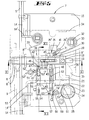
Figur 2- in vergrößerter Einzeldarstellung das Zusatzschloß bei zurückgezogenem Sperriegel, in Richtung der Schloßdecke gesehen,
Figur 3- eine der
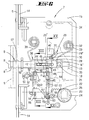
Figur 2 entsprechende Darstellung, wobei die Schloßdecke fortgelassen ist, Figur 4- eine Ansicht des Zusatzschlosses bei fortgelassener Schloßdecke und nicht veranschaulichtem Treibstangen-Anschlußschieber,
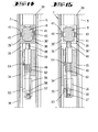
Figur 5- das Zusatzschloß mit vorgeschlossenem Riegel nach erfolgter erster Schließbetätigung des Hauptschlosses,
Figur 6- das Zusatzschloß bei vorverlagertem Sperriegel entsprechend der Stellung, die sich nach der ersten Rückschließbetätigung des Hauptschlosses ergibt,
Figur 7- das Zusatzschloß mit vorverlagertem Sperriegel gemäß der Stellung, welche bei erneutem Vorschließen des Hauptriegels auftritt,
Figur 8- das Zusatzschloß bei von der Nuß vorverlagertem Sperriegel,
Figur 9- die Folgedarstellung der
Figur 8, und zwar bei Rückschließbetätigung der Nuß bei gleichzeitiger Beaufschlagung eines Auslösers zur Zurückverlagerung des zweiten und ersten Sperrfingers, Figur 10- den Schnitt nach der Linie X-X in
Figur 2, Figur 11- den Schnitt nach der Linie XI-XI in
Figur 5, Figur 12- den Schnitt nach der Linie XII-XII in
Figur 5, Figur 13- den Schnitt nach der Linie XIII-XIII in
Figur 6, Figur 14- den Schnitt nach der Linie XIV-XIV in
Figur 4 und Figur 15- den Schnitt nach der Linie XV-XV in
Figur 6.
- FIG. 1
- a door provided with a configured espagnolette lock,
- FIG. 2
- in enlarged detail the additional lock with the locking bolt withdrawn, seen in the direction of the lock cover,
- FIG. 3
- 2 a representation corresponding to FIG. 2, the lock cover being omitted,
- FIG. 4
- a view of the additional lock with left lock cover and unillustrated espagnolette slide,
- FIG. 5
- the additional lock with vorgeschlossenem latch after the first closing operation of the main castle,
- FIG. 6
- the additional lock with vorverlagertem locking bar according to the position that results after the first Rückschließbetätigung the main lock,
- FIG. 7
- the additional lock with vorverlagertem locking bar according to the position which occurs when re-closing of the main bolt,
- FIG. 8
- the additional lock in case of the locking bar,
- FIG. 9
- the following illustration of Figure 8, namely in Rückschließbetätigung the nut with simultaneous application of a trigger for relocating the second and first locking finger,
- FIG. 10
- the section along the line XX in Figure 2,
- FIG. 11
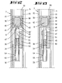
- the section along the line XI-XI in Figure 5,
- FIG. 12
- the section along the line XII-XII in Figure 5,
- FIG. 13
- the section along the line XIII-XIII in Figure 6,
- FIG. 14
- the section along the line XIV-XIV in Figure 4 and
- FIG. 15
- the section along the line XV-XV in Figure 6.
Mit der Ziffer 1 ist in Figur 1 eine Tür bezeichnet, welche mitttels Scharniere 2 an einem Türrahmen 3 angelenkt ist.The
Auf der den Scharnieren 2 gegenüberliegenden Seite nimmt die Tür einen Treibstangenverschluß 4 auf. Letzterer besitzt eine türfalzseitige Stulpe 5 mit daran festgelegtem Hauptschloß 6. Oberhalb desselben befindet sich an der Stulpe 5 ein als Sperrbügelschloß ausgebildetes Zusatzschloß 7. Das bedeutet, daß dessen Sperriegel 8 mit einem rahmenseitig angelenkten, längsgeschlitzten Sperrbügel 9 zusammenwirkt. Oberhalb des Zusatzschlosses 7 befindet sich weiter ein Zapfenriegelschloß 10. Dieses entspricht in seinem Aufbau dem untenhalb des Hauptschlosses 4 angeordneten Zapfenriegelschloß 11.On the opposite side of the
Das Hauptschloß 4 ist mit einer Falle 12 und einem Hauptriegel 13 ausgestattet. Dieser ist vorzugsweise zweitourig durch Schlüsselbetätigung vor- und zurückschließbar. Einhergehend mit einer Verlagerung des Hauptriegels 13 wird eine von der Stulpe 5 abgedeckte Treibstange 14 verlagert, welche ihre Bewegung auf das Zusatzschloß 7 und die Zapfenriegelschlösser 10, 11 überträgt.The
Im einzelnen besitzt das Zusatzschloß 7 einen mit der Stulpe 5 verbundenen Schloßboden 15, parallel zu welchem sich eine Schloßdecke 16 erstreckt. Im Zwischenraum zwischen Schloßboden und Schloßdecke 16 befindet sich das Schloßeingerichte. Es sind dies der in der Schloßquermittelebene geführte Sperriegel 8. Dessen Riegelkopf 8' durchgreift eine querschnittsangepaßte Durchbrechung 17 der Stulpe 5, während der Riegelschwanz 8'' mittels beidseitig vorstehender Zapfen 18 in Querschlitzen 19, 20 von Schloßboden 15 und Schloßdecke 16 geführt sind. Nach unten gerichtet setzt sich der Sperriegelschwanz 8'' in einen Ausleger 21 fort. Dieser bildet eine parallel zur Verlagerungsrichtung des Sperriegels 8 verlaufende Zahnstange 22 aus, die mit der Verzahnung 23 einer Nuß 24 zusammenwirkt. Gelagert ist diese in bekannter Weise in Schloßboden 15 und Schloßdecke 16. Radial gerichtet geht von der Nuß ein Anschlag 25 aus, der in einen Bogenschlitz 26 der Schloßdecke 16 eintaucht. Der Bogenschlitz 26 ist so lang gewählt, daß die Nuß 24 um 90° zu drehen vermag. Figur 1 veranschaulicht eine Innenbetätigungshandhabe 27, welche in geeigneter Weise mit der Nuß 24 verbunden ist.In particular, the
An der dem Ausleger 21 gegenüberliegenden Seite trägt der Riegelschwanz 8'' ein Lagerböckchen 28 für einen doppelarmigen Mitnahmehebel 29. Eine auf der Lagerachse 30 des Mitnahmehebels 29 angeordnete Drehfeder 31 belastet den Mitnahmehebel 29 entgegen Uhrzeigerrichtung derart, daß sich der dem Sperriegel 8 zugewandte Hebelarm 29' an der oberen Längskante des Sperriegels 8 abstützt, vgl. Figur 3. An dem einen stumpfen Winkel zu dem Hebelarm 29' einschließenden anderen Hebelarm 29'' greift die vorgenannte Drehfeder 31 an.At the
Auf einen Vierkantzapfen 32 des Schloßbodens 15 ist eine spiralförmig gewundene Rückdrückfeder 33 aufgesteckt, welche den Sperriegel 8 in Schloßeinwärtsrichtung belastet. Zwischen dem Sperriegel 8 und der Schloßdecke 16 ist ein Treibstangen-Anschlußschieber 34 geführt. Gekuppelt ist dieser mit den Endabschnitten 14' der auf Höhe des Zusatzschlosses 7 geteilten Treibstange 14. Im rückwärtigen, der Stulpe 5 abgekehrten Bereich besitzt der Treibstangen-Anschlußschieber 34 einen sich keilförmig erbreiternden Keilschlitz 35, in den der Zapfen 18 eintaucht. Das Vorschließen des Sperrriegels 8 erfolgt dabei über die schräg zur Ausschlußrichtung des Sperriegels 8 verlaufende Schrägwand 35', welche sich am oberen Ende in eine Nische 35'' fortsetzt.On a
Auf der der Stulpe 5 zugekehrten Seite besitzt der Treibstangen-Anschlußschieber 34 eine Aussparung 36, welche durch einen schmalen Längssteg 37 von dem Keilschlitz 35 getrennt ist. An dem Längssteg 37 stützt sich ein den Sperriegel 8 hülsenförmig umfassender Schieber 38 ab. Eine Spiralfeder 39 beaufschlagt den Schieber 38 in Richtung des Längssteges 37. Der Hebelarm 29' des Mitnahmehebels 29 endet mit geringem Abstand vor der rückwärtigen Kante des Schiebers 38, vgl. die Ausgangsstellung in Figur 3. Der andere Hebelarm 29'' des Mitnahmehebels 29 wirkt zusammen mit einem schloßbodenseitigen Anschlag 40.On the side facing the
Die dem Schloßboden 15 und der Schloßdecke 16 zugekehrten Breitseitenwände 38' des Schiebers 38 besitzen je einen rückwärtig offenen, in Riegellängsrichtung verlaufenden Längsschlitz 41. Die inneren Enden der Längsschlitze 41 sind dabei zu Aussteuerungsschrägen 42 geformt. Jede Aussteuerungsschräge 42 wirkt zusammen mit dem abgewinkelt verlaufenden Ende 43' je einer Blattfeder 43. Deren Breite ist etwas geringer als die Breite der Längsschlitze 41. Befestigt sind die Blattfedern 43 beiderseits des Riegelschwanzes 8', und zwar auf gegenüberliegenden Seiten desselben, vgl. Figur 10. Jede Blattfeder 43 trägt je ein Rastmittel 44 in Form eines Rastzapfens. Diese Rastmittel 44 tauchen in die Längsschlitze 41 des Schiebers 38 ein. Aufgrund der Federvorspannung werden die Rastmittel 44 gegen Schloßboden 15 und Schloßdecke 16 gedrückt. Die Rastmittel 44 wirken zusammen mit Rastöffnungen 45 in Schloßboden 15 und Schloßdecke 16.The lock bottom 15 and the
Die vorgenannten Rastmittel - Rastzapfen 44 und Rastöffnungen 45 - bilden eine Kupplung, welche den Sperriegel 8 in der vorgeschlossenen Stellung hält, was später noch näher erläutert wird.The aforementioned locking means - locking
An seiner Unterseite trägt der Schieber 38 einen abgeschrägt verlaufenden Sperrfortsatz 46. Letzterer erstreckt sich bei zurückverlagertem Sperriegel 8 zwischen einem ersten Sperrfinger 47 und einem zweiten Sperrfinger 48, welche quer zur Bewegungsrichtung des Sperriegels 8 in einem am Schloßboden 15 befestigten Gehäuse 49 geführt sind. Eine Druckfeder 50 belastet den drehgesicherten ersten Sperrfinger 47 in Richtung des Sperriegels 8. Am oberen Ende formt der Sperrfinger 47 einen fallenartig abgeschrägten Anschlag 47' zum Zusammenwirken mit dem Sperrfortsatz 46. Radial gerichtet geht vom ersten Sperrfinger 47 ein einen Längsschlitz des Gehäuses 49 durchsetzender Mitnahmestift 51 aus, welcher mit einer am Schloßboden gelagerten Wippe 52 zusammenwirkt. Der eine Wippenarm 52' wirkt dabei zusammen mit dem Mitnahmestift 51, während der andere Wippenarm 52'' gemäß Figur 3 sich an einem ersten Vorsprung 53 des Treibstangen-Anschlußschiebers 34 abstützt. Das aus dem Gehäuse 49 herausragende untere Ende des Sperrfingers 47 trägt einen Querstift 54, welcher einen Längsschlitz 55 eines auf das untere Ende des Sperrfingers 47 aufgesteckten Schuhes 56 durchsetzt. Dieser trägt einen rechtwinklig zum zweiten Sperrfinger 48 verlaufenden Kupplungsstift 57. Derselbe durchgreift einen Schlitz 58 am unteren Ende des Sperrfingers 48. Das in radialer Richtung über den zweiten Sperrfinger 48 hinausragende querschnittsvergrößerte Ende des Kupplungsstiftes 57 wird beaufschlagt von einem Arm 59' eines am Schloßboden 15 gelagerten doppelarmigen Auslösers 59. Eine Zugfeder 60 belastet den Auslöser 59 entgegen Uhrzeigerrichtung derart, daß sich der Arm 59' an dem Kupplungsstift 57 abstützt, vgl. Figur 4. Der dem Arm 59' gegenüberliegende andere Arm 59'' wirkt zusammen mit einem Radialnocken 61 der Nuß 24. Der im Gehäuse 49 drehgesicherte zweite Sperrfinger 48 wird von einer Druckfeder 62 in Richtung des Schiebers 38 belastet derart, daß das obere Ende des zweiten Sperrfingers 48 sich an der Unterseite des Schiebers 38 abstützt, vgl. insbesondere Figur 4. Am unteren Ende besitzt der zweite Sperrfinger 48 einen in Richtung des Treibstangen-Anschlußschiebers ausladenden Nocken 63, welcher mit einem an dem Treibstangen-Anschlußschieber 34 angeordneten zweiten Vorsprung 64 zusammenwirkt.The latter extends at zurückverlagertem locking
Es stellt sich folgende Wirkungsweise ein:The following mode of action occurs:
Beim Vorschließen des Hauptriegels 13 des Hauptschlosses 6 erfährt die Treibstange 14 eine Abwärtsverlagerung. Einhergehend wird der Treibstangen-Anschlußschieber 34 des Zusatzschlosses 7 ebenfalls in Abwärtsrichtung mitgenommen. Über die Schrägwand 35' des Keilschlitzes 35 im Zusammenwirken mit dem Zapfen 18 am Riegelschwanz 8'' erfährt der Sperriegel 8 eine Vorverlagerung in Ausschließrichtung. Der sich vorverlagernde Sperriegel 8 schleppt über den Mitnahmehebel 29 den Schieber 38 mit. In der Endphase der Vorschließverlagerung des Sperriegels 8 treten die an den Blattfedern 43 befindlichen Rastzapfen 44 in die Rastöffnungen 45 von Schloßboden 15 und Schloßdecke 16 ein, wodurch bei der ersten Vorschließbetätigung der Sperriegel 8 von der Schloßbetätigung entkuppelt ist. Sodann beaufschlagt der Hebelarm 29'' des Mitnahmehebels 29 den schloßgehäuseseitigen Anschlag 40 und verschwenkt in eine Freigabestellung gemäß Figur 5. Während der Vorverlagerung des Schiebers 38 zusammen mit dem Sperriegel 8 hat der Sperrfortsatz 46 den ersten Sperrfinger 47 überfahren, so daß dann der Sperrfortsatz 46 vor dem Anschlag 47' des ersten Sperrfingers 47 liegt. Der zweite Sperrfinger 48 erstreckt sich nach der ersten Schließbetätigung des Hauptschlosses hinter dem Schieber 38 und stützt sich an der Unterseite des Sperriegels 8 ab, siehe ebenfalls Figur 5. Sodann hat bei dieser Vorschließbetätigung der mitgedrehten Nuß 24 der Radialnocken 61 den Arm 59'' des Auslösers 59 überlaufen. Die Drehbetätigung der Nuß 24 ist dabei auf die Innenbetätigungshandhabe 27 übertragen worden.When vorschluss the
Ferner veranschaulicht Figur 5, daß der mit einer Ringnut 8''' versehene Riegelkopf 8' in Eingriff zum rahmenseitigen Sperrbügel 9 getreten ist, derart, daß sich der Sperrbügel 9 und dessen Schlitzung auf Höhe der Ringnut 8''' erstreckt.Further, Figure 5 illustrates that the provided with an annular groove 8 '''bolt head 8' is engaged with the frame-
Bei der ersten Rückschließbetätigung des Hauptschlosses 6 wird der Hauptriegel 13 zurückgeschlossen. Ferner bewegt sich der Treibstangen-Anschlußschieber 34 in Aufwärtsrichtung, wobei der erste Vorsprung 53 des Treibstangen-Anschlußschiebers 34 gegen den Wippenarm 52'' der Wippe 52 stößt und diese in Uhrzeigerrichtung verschwenkt, vgl. Figur 6. Der Wippenarm 52' zieht über den Mitnahmestift 51 den ersten Sperrfinger 47 zurück unter Freigabe des Schiebers 38, welcher unter der Wirkung der Spiralfeder 39 aus der zuvor eingenommenen ersten Raststellung in die zweite Raststellung fährt. Begrenzt ist dieses durch den zweiten Sperrfinger 48, welcher von der Rückseite des Schiebers 38 beaufschlagt wird. Die um diesen Betrag rückverlagerte Schieberstellung ist gestrichelt in Figur 11 veranschaulicht. Die Aussteuerungsschrägen 42 verlagern dabei noch nicht die Enden 43' der Blattfedern 43, so daß die Rastzapfen 44 in Eingriff zu den Rastöffnungen 45 verbleiben. Der Sperriegel 8 nimmt daher weiterhin seine Vortrittsstellung ein, während der Hauptriegel 13 zurückgeschlossen ist.In the first return operation of the
Die Zurückverlagerung des Sperriegels 8 verlangt eine erneute Vorschließbetätigung des Hauptschlosses 6, und der Hauptriegel 13 fährt vor. Ferner bewegt sich der Treibstangen-Anschlußschieber 34 ausgehend von Figur 6 in Abwärtsrichtung, wobei die Stellung nach Figur 7 erzielt wird. Durch den zweiten Vorsprung 64 des Treibstangen-Anschlußschiebers 34 wird dabei der Nocken 63 des Sperrfingers 48 beaufschlagt und dieser dadurch in Freigabestellung zum Schieber 38 gebracht. Dieser kann sich durch die Kraft der Spiralfeder 39 relativ zum Sperriegel 8 verlagern und stützt sich nach erfolgter Verlagerung an dem Lagerböckchen 28 des Sperriegels 8 ab. Der betreffende Verlagerungsweg reicht jedoch aus, um mittels der Aussteuerungsschrägen 42 die Blattfedern 43 an ihren Enden 43' zu beaufschlagen, wobei die Rastzapfen 44 die Rastöffnungen 45 verlassen, vgl. strichpunktierte Darstellung in Figur 11. Der Sperriegel 8 ist dann nur noch durch den Keilschlitz 35 gehalten. Erfolgt ausgehend von dieser Stellung die zweite Rückschließbetätigung des Hauptschlosses 6, so wandert der Treibstangen-Anschlußschieber 34 in Aufwärtsrichtung, so daß aufgrund der Rückdrückfeder 33 der Sperriegel 8 zurückgezogen wird, wobei der Zapfen 18 des Sperriegelschwanzes 8'' entlang der Schrägwand 35' des Keilschlitzes 35 gleitet. Einhergehend mit dem Zurückziehen des Sperriegels wird die Nuß 24 aufgrund der Verzahnung um 90° zurückgedreht. Hierbei überläuft der Nocken 63 der Nuß 24 den Auslöser 59, welcher zwangsläufig federnd ausweicht und danach wieder in seine Ausgangsstellung gemäß Figur 3 und 4 zurücktritt.The backward displacement of the
Es ist jedoch auch möglich, den Sperriegel 8 ausschließlich durch Handhabenbetätigung in die Vorschließstellung zu bringen. Bei dem damit verbundenen Drehen der Nuß 24 wird über die Zahnung der Sperriegel 8 in Vorschlußrichtung bewegt. Der Mitnahmehebel 29 verlagert den Schieber 38 und wird durch den ersten Sperrfinger 47 gesichert, vgl. Figur 8. Der Sperriegel 8 verrastet in dieser vorgeschlossenen Stellung dadurch, daß die Rastzapfen 44 in die Rastöffnungen 45 eingreifen. Der zweite Sperrfinger 48 erstreckt sich vor der Rückseite des Schiebers 38. Ferner hat der Radialnocken 61 den Auslöser 59 überlaufen. Begrenzt ist die Drehbewegung der Nuß 24 durch den Bogenschlitz 26. Erfährt nun die Nuß 24 ihre Rückschließbetätigung, so beaufschlagt der Radialnocken 63 den Auslöser 59, welcher über den Kupplungsstift 57 sowohl den ersten Sperrfinger 47 als auch den zweiten Sperrfinger 48 in eine Freigabestellung zurückzieht. Der Schieber 38 ist daher zur Verlagerung freigegeben, wobei er die Verrastung zwischen Rastzapfen 44 und Rastlöchern 45 aufhebt, so daß federbelastet der Sperriegel 8 zurückfahren kann. Dieses ist möglich, weil sich der Zapfen 18 in dem größten Bereich des Keilschlitzes 35 befindet.However, it is also possible to bring the
Es ist jedoch auch möglich, nach der ersten Rückschließbetätigung des Hauptschlosses den Sperriegel 8 durch Handhabenverlagerung zurückzuziehen. Dann wird ebenfalls über den Radialnocken 61 der Nuß 24 der Sperrfinger 48 aus seiner Haltestellung zum Schieber 38 gebracht, woraufhin dieser sich in Richtung des Riegelschwanzes 8'' des Sperriegels verlagert und dessen Verrastung aufhebt.However, it is also possible to withdraw the
Claims (12)
- An espagnolette lock (4) comprising a main lock (6) on the wing, which can be operated by a key and has a main bolt (13), and comprising a drive rod (14) which can be displaced along a faceplate (5) by actuation of the main lock (6) for actuation of a locking bolt (8) of an additional lock (7) which belongs to the espagnolette lock and cooperates with a blocking pivoting stirrup (9) on the frame, characterized in that after an actuation of the main lock (6), the locking bolt (8) of the additional lock (7) is extended into the locking position together with the main bolt (13) by drive rod actuation, and after a first unlocking actuation of the main lock (6), the main bolt (13) is drawn back, and after a second unlocking actuation, the locking bolt (8) is drawn back.
- An espagnolette lock according to Claim 1, characterized in that between the first and second unlocking actuation, the main bolt (13) is again extended.
- An espagnolette lock according to one of the preceding claims, characterized by a coupling, in particular located in the additional lock (7), the coupling uncoupling the locking bolt (8) during the first extending actuation of the lock actuation.
- An espagnolette lock according to Claim 3, characterized in that the coupling has detent means (44, 45), which hold the locking bolt (8) in the extended position, which detent position is released for the second unlocking actuation.
- An espagnolette lock according to any of the preceding claims, characterized by a first blocking finger (47), which holds a slide (38) located on the locking bolt (8) in a first detent position, which blocking finger (47) is retracted in the first unlocking position and unblocks the slide (38) for displacement into a second detent position in which the slide (38) is held by a second blocking finger (48), which blocking finger is retracted in the position in which the main lock (13) is again extended and unblocks the slide (3 8) for release of the locking bolt detent.
- An espagnolette lock according to any of the preceding claims, characterized by a drive-rod effected advance of the locking bolt (8) into a detent position after a first unlocking actuation of the main lock (6), out of which the locking bolt (8) is displaced back by the force of a return spring (33) when detent release is effected by drive-rod action after a second unlocking actuation of the main lock (6), the spring being loaded when the bolt is advanced.
- An espagnolette lock according to any of the preceding Claims 4 to 6, characterized in that the locking bolt (8) is advanced into the detent position during a first drive rod displacement, is brought into a release position during a second drive rod displacement, and is drawn back during a third drive rod displacement.
- An espagnolette lock according to any of Claims 5 to 7, characterized in that the slide (3 8) is carried along by means of a drive lever (29) located on the locking bolt (8) during a first advancing actuation, the lever being released in the final phase of the advancing actuation into an unblocking position with respect to the slide (38).
- An espagnolette lock according to any of Claims 5 to 8, characterized by a first projection (53) located on a drive rod connection slide (34), the projection displacing back the first blocking finger (47), in particular by way of a rocker (52), and characterized also by a second projection (64) located on the drive rod connection slide (34), this projection displacing back the second blocking finger (47) during the second drive rod actuation.
- An espagnolette lock according to any of the preceding claims, characterized in that for manual actuation of the locking bolt (8), the locking bolt (8) is coupled by way of a toothed rod (22) to the toothing (23) of a follower (24) of the additional lock (7).
- An espagnolette lock according to Claim 10, characterized in that the follower (24) actuates a release feature (59) during an unlocking actuation for reverse displacement of the second blocking finger (48).
- An espagnolette lock according to any of the preceding claims, characterized in that the drive of the locking bolt (8) into the advanced position is effected by way of the sloping wall (35') of a wedge-form slot (35) which widens in the shape of a wedge.
Applications Claiming Priority (2)
| Application Number | Priority Date | Filing Date | Title |
|---|---|---|---|
| DE29602756U | 1996-02-16 | ||
| DE29602756U DE29602756U1 (en) | 1996-02-16 | 1996-02-16 | Espagnolette lock |
Publications (3)
| Publication Number | Publication Date |
|---|---|
| EP0790376A2 EP0790376A2 (en) | 1997-08-20 |
| EP0790376A3 EP0790376A3 (en) | 1997-08-27 |
| EP0790376B1 true EP0790376B1 (en) | 2007-06-27 |
Family
ID=8019591
Family Applications (1)
| Application Number | Title | Priority Date | Filing Date |
|---|---|---|---|
| EP97101678A Expired - Lifetime EP0790376B1 (en) | 1996-02-16 | 1997-02-04 | Espagnolette lock |
Country Status (4)
| Country | Link |
|---|---|
| EP (1) | EP0790376B1 (en) |
| AT (1) | ATE365856T1 (en) |
| DE (2) | DE29602756U1 (en) |
| ES (1) | ES2285717T3 (en) |
Families Citing this family (1)
| Publication number | Priority date | Publication date | Assignee | Title |
|---|---|---|---|---|
| FR2825111B1 (en) * | 2001-05-23 | 2004-01-30 | Ferco Int Usine Ferrures | DOOR, WINDOW OR SIMILAR INTERLOCKER LATCH |
Family Cites Families (3)
| Publication number | Priority date | Publication date | Assignee | Title |
|---|---|---|---|---|
| AT366750B (en) * | 1980-11-13 | 1982-05-10 | Grundmann Rohrbacher Schlosser | DOOR LOCK |
| FR2576628B1 (en) * | 1985-01-30 | 1989-06-30 | Grundmann Rohrbacher Schlosser | DOOR CLOSURE COMPRISING A LOCK WITH LOCK AND RACK AND A SECURITY LOCKING ELEMENT CONNECTED TO THE LOCK. |
| DE29509503U1 (en) * | 1995-06-14 | 1995-09-14 | Gretsch Unitas Gmbh | Multiple locking system |
-
1996
- 1996-02-16 DE DE29602756U patent/DE29602756U1/en not_active Expired - Lifetime
-
1997
- 1997-02-04 AT AT97101678T patent/ATE365856T1/en not_active IP Right Cessation
- 1997-02-04 ES ES97101678T patent/ES2285717T3/en not_active Expired - Lifetime
- 1997-02-04 EP EP97101678A patent/EP0790376B1/en not_active Expired - Lifetime
- 1997-02-04 DE DE59712854T patent/DE59712854D1/en not_active Expired - Fee Related
Also Published As
| Publication number | Publication date |
|---|---|
| DE29602756U1 (en) | 1997-06-19 |
| EP0790376A2 (en) | 1997-08-20 |
| EP0790376A3 (en) | 1997-08-27 |
| ES2285717T3 (en) | 2007-11-16 |
| ATE365856T1 (en) | 2007-07-15 |
| DE59712854D1 (en) | 2007-08-09 |
Similar Documents
| Publication | Publication Date | Title |
|---|---|---|
| DE3836693C2 (en) | Espagnolette lock | |
| EP2951369B1 (en) | Panic lock | |
| DE3447748C2 (en) | ||
| EP0796968B1 (en) | Closure device | |
| DE102006059565A1 (en) | Locking system for doors, windows or the like, in particular espagnolette lock with panic function and multipoint locking | |
| DE3836694C2 (en) | Espagnolette lock | |
| EP0413177A1 (en) | Lock for driving rod | |
| EP1020597B1 (en) | Espagnolette lock with a main lock and an auxiliary lock | |
| EP1020594B1 (en) | Espagnolette lock | |
| EP1087084A2 (en) | Lock with bolt and latch and with increased shot of the bolt | |
| EP0670403B1 (en) | Doorlock, especially mortise lock | |
| DE2738746C3 (en) | Release device for a panic door lock with latch and bolt | |
| EP2072725A2 (en) | Espagnolette locking device | |
| DE4114007A1 (en) | Main rod lock operated by pushbutton - incorporates stop component preventing drive unit moving from closed to open positions | |
| EP2072723A2 (en) | Espagnolette locking device | |
| EP0790376B1 (en) | Espagnolette lock | |
| EP0496076B1 (en) | Espagnolette lock | |
| DE19822951A1 (en) | House door lock e.g. for surgeries with spring and auxiliary bolts | |
| EP0972900B1 (en) | Espagnolette lock | |
| EP0990758A2 (en) | Additional lock for espagnolette | |
| EP0974721B1 (en) | Lock with several bolts | |
| DE2605763C3 (en) | Espagnolette lock with latch | |
| DE19756116B4 (en) | Bolt lock | |
| EP0795665A2 (en) | Mortise lock | |
| DE19749023B4 (en) | Lock for doors, windows or the like |
Legal Events
| Date | Code | Title | Description |
|---|---|---|---|
| PUAI | Public reference made under article 153(3) epc to a published international application that has entered the european phase |
Free format text: ORIGINAL CODE: 0009012 |
|
| PUAL | Search report despatched |
Free format text: ORIGINAL CODE: 0009013 |
|
| AK | Designated contracting states |
Kind code of ref document: A2 Designated state(s): AT BE CH DE DK ES FR GB IE IT LI NL SE |
|
| AK | Designated contracting states |
Kind code of ref document: A3 Designated state(s): AT BE CH DE DK ES FR GB IE IT LI NL SE |
|
| 17P | Request for examination filed |
Effective date: 19971219 |
|
| GRAP | Despatch of communication of intention to grant a patent |
Free format text: ORIGINAL CODE: EPIDOSNIGR1 |
|
| GRAS | Grant fee paid |
Free format text: ORIGINAL CODE: EPIDOSNIGR3 |
|
| GRAA | (expected) grant |
Free format text: ORIGINAL CODE: 0009210 |
|
| RAP1 | Party data changed (applicant data changed or rights of an application transferred) |
Owner name: KFV KARL FLIETHER GMBH & CO. KG |
|
| AK | Designated contracting states |
Kind code of ref document: B1 Designated state(s): AT BE CH DE DK ES FR GB IE IT LI NL SE |
|
| REG | Reference to a national code |
Ref country code: GB Ref legal event code: FG4D Free format text: NOT ENGLISH |
|
| REG | Reference to a national code |
Ref country code: CH Ref legal event code: EP |
|
| REG | Reference to a national code |
Ref country code: IE Ref legal event code: FG4D Free format text: LANGUAGE OF EP DOCUMENT: GERMAN |
|
| REF | Corresponds to: |
Ref document number: 59712854 Country of ref document: DE Date of ref document: 20070809 Kind code of ref document: P |
|
| GBT | Gb: translation of ep patent filed (gb section 77(6)(a)/1977) |
Effective date: 20070831 |
|
| PG25 | Lapsed in a contracting state [announced via postgrant information from national office to epo] |
Ref country code: SE Free format text: LAPSE BECAUSE OF FAILURE TO SUBMIT A TRANSLATION OF THE DESCRIPTION OR TO PAY THE FEE WITHIN THE PRESCRIBED TIME-LIMIT Effective date: 20070927 |
|
| REG | Reference to a national code |
Ref country code: CH Ref legal event code: NV Representative=s name: R. A. EGLI & CO. PATENTANWAELTE |
|
| ET | Fr: translation filed | ||
| REG | Reference to a national code |
Ref country code: ES Ref legal event code: FG2A Ref document number: 2285717 Country of ref document: ES Kind code of ref document: T3 |
|
| REG | Reference to a national code |
Ref country code: IE Ref legal event code: FD4D |
|
| PG25 | Lapsed in a contracting state [announced via postgrant information from national office to epo] |
Ref country code: IE Free format text: LAPSE BECAUSE OF FAILURE TO SUBMIT A TRANSLATION OF THE DESCRIPTION OR TO PAY THE FEE WITHIN THE PRESCRIBED TIME-LIMIT Effective date: 20070627 |
|
| PG25 | Lapsed in a contracting state [announced via postgrant information from national office to epo] |
Ref country code: DK Free format text: LAPSE BECAUSE OF FAILURE TO SUBMIT A TRANSLATION OF THE DESCRIPTION OR TO PAY THE FEE WITHIN THE PRESCRIBED TIME-LIMIT Effective date: 20070627 |
|
| PLBE | No opposition filed within time limit |
Free format text: ORIGINAL CODE: 0009261 |
|
| STAA | Information on the status of an ep patent application or granted ep patent |
Free format text: STATUS: NO OPPOSITION FILED WITHIN TIME LIMIT |
|
| 26N | No opposition filed |
Effective date: 20080328 |
|
| BERE | Be: lapsed |
Owner name: KFV KARL FLIETHER G.M.B.H. & CO. KG Effective date: 20080228 |
|
| REG | Reference to a national code |
Ref country code: CH Ref legal event code: PL |
|
| GBPC | Gb: european patent ceased through non-payment of renewal fee |
Effective date: 20080204 |
|
| PG25 | Lapsed in a contracting state [announced via postgrant information from national office to epo] |
Ref country code: LI Free format text: LAPSE BECAUSE OF NON-PAYMENT OF DUE FEES Effective date: 20080229 Ref country code: CH Free format text: LAPSE BECAUSE OF NON-PAYMENT OF DUE FEES Effective date: 20080229 |
|
| NLV4 | Nl: lapsed or anulled due to non-payment of the annual fee |
Effective date: 20080901 |
|
| PG25 | Lapsed in a contracting state [announced via postgrant information from national office to epo] |
Ref country code: NL Free format text: LAPSE BECAUSE OF NON-PAYMENT OF DUE FEES Effective date: 20080901 |
|
| REG | Reference to a national code |
Ref country code: FR Ref legal event code: ST Effective date: 20081031 |
|
| PG25 | Lapsed in a contracting state [announced via postgrant information from national office to epo] |
Ref country code: DE Free format text: LAPSE BECAUSE OF NON-PAYMENT OF DUE FEES Effective date: 20080902 |
|
| PG25 | Lapsed in a contracting state [announced via postgrant information from national office to epo] |
Ref country code: BE Free format text: LAPSE BECAUSE OF NON-PAYMENT OF DUE FEES Effective date: 20080228 |
|
| PG25 | Lapsed in a contracting state [announced via postgrant information from national office to epo] |
Ref country code: FR Free format text: LAPSE BECAUSE OF NON-PAYMENT OF DUE FEES Effective date: 20080229 Ref country code: AT Free format text: LAPSE BECAUSE OF NON-PAYMENT OF DUE FEES Effective date: 20080204 |
|
| REG | Reference to a national code |
Ref country code: ES Ref legal event code: FD2A Effective date: 20080205 |
|
| PG25 | Lapsed in a contracting state [announced via postgrant information from national office to epo] |
Ref country code: GB Free format text: LAPSE BECAUSE OF NON-PAYMENT OF DUE FEES Effective date: 20080204 |
|
| PG25 | Lapsed in a contracting state [announced via postgrant information from national office to epo] |
Ref country code: ES Free format text: LAPSE BECAUSE OF NON-PAYMENT OF DUE FEES Effective date: 20080205 |
|
| PG25 | Lapsed in a contracting state [announced via postgrant information from national office to epo] |
Ref country code: IT Free format text: LAPSE BECAUSE OF NON-PAYMENT OF DUE FEES Effective date: 20080204 |