EP0790376B1 - Serrure à Crémone - Google Patents
Serrure à Crémone Download PDFInfo
- Publication number
- EP0790376B1 EP0790376B1 EP97101678A EP97101678A EP0790376B1 EP 0790376 B1 EP0790376 B1 EP 0790376B1 EP 97101678 A EP97101678 A EP 97101678A EP 97101678 A EP97101678 A EP 97101678A EP 0790376 B1 EP0790376 B1 EP 0790376B1
- Authority
- EP
- European Patent Office
- Prior art keywords
- lock
- locking bolt
- actuation
- main
- bolt
- Prior art date
- Legal status (The legal status is an assumption and is not a legal conclusion. Google has not performed a legal analysis and makes no representation as to the accuracy of the status listed.)
- Expired - Lifetime
Links
Images


Classifications
-
- E—FIXED CONSTRUCTIONS
- E05—LOCKS; KEYS; WINDOW OR DOOR FITTINGS; SAFES
- E05C—BOLTS OR FASTENING DEVICES FOR WINGS, SPECIALLY FOR DOORS OR WINDOWS
- E05C17/00—Devices for holding wings open; Devices for limiting opening of wings or for holding wings open by a movable member extending between frame and wing; Braking devices, stops or buffers, combined therewith
- E05C17/02—Devices for holding wings open; Devices for limiting opening of wings or for holding wings open by a movable member extending between frame and wing; Braking devices, stops or buffers, combined therewith by mechanical means
- E05C17/04—Devices for holding wings open; Devices for limiting opening of wings or for holding wings open by a movable member extending between frame and wing; Braking devices, stops or buffers, combined therewith by mechanical means with a movable bar or equivalent member extending between frame and wing
- E05C17/12—Devices for holding wings open; Devices for limiting opening of wings or for holding wings open by a movable member extending between frame and wing; Braking devices, stops or buffers, combined therewith by mechanical means with a movable bar or equivalent member extending between frame and wing consisting of a single rod
- E05C17/16—Devices for holding wings open; Devices for limiting opening of wings or for holding wings open by a movable member extending between frame and wing; Braking devices, stops or buffers, combined therewith by mechanical means with a movable bar or equivalent member extending between frame and wing consisting of a single rod pivoted only at one end and having an elongated slot
- E05C17/166—Security devices
-
- E—FIXED CONSTRUCTIONS
- E05—LOCKS; KEYS; WINDOW OR DOOR FITTINGS; SAFES
- E05C—BOLTS OR FASTENING DEVICES FOR WINGS, SPECIALLY FOR DOORS OR WINDOWS
- E05C9/00—Arrangements of simultaneously actuated bolts or other securing devices at well-separated positions on the same wing
- E05C9/18—Details of fastening means or of fixed retaining means for the ends of bars
- E05C9/1825—Fastening means
- E05C9/1833—Fastening means performing sliding movements
- E05C9/1841—Fastening means performing sliding movements perpendicular to actuating bar
Definitions
- a drive rod lock of the type in question is known from the DE 35 03 466 C2 , wherein the Vorschhogrum the locking bolt of the auxiliary lock by means of a located on the inside of the door handle. In the release position of the locking bolt is brought back when closing the locked lock of the main lock. This means that unlocking the door not only the main lock, but also the auxiliary lock is opened.
- the object of the invention is based on the object, a generic espagnolette to design so that in addition to a simplified operation of the safety value is increased.
- a generic espagnolette is created, which is characterized by a simplified operation in addition to an increased safety value.
- the simplified operation results from the fact that when locking the main latch of the main lock by means of the key accompanying the locking bolt of the auxiliary lock reaches its prelocking position. So it does not have to be a separate closing operation to precede the locking bolt of the auxiliary lock.
- This also results in the increased safety value. Namely, it can not happen that forgetfulness when vorMedic the main bolt preclusion of the locking bolt is omitted. Always after closing action of the main bolt of the closing engagement of the main bolt and locking bolt is brought about. Furthermore, the advantage is maintained that after a first return operation of the main lock only the main latch is closed back. The closing of the Sperriegels then takes place after a second Ruschteurbetuschistor the main bolt, also by key operation.
- this has the coupling latching means which hold the locking bolt in the pre-closed position, which locking position is canceled in the second remindsch perennialbet decisivist.
- the procedure is to provide a first locking finger, which holds a slider arranged on the locking bar in a first detent position, which locking finger is retracted in the first return position and releases the slide for displacement in a second detent position in which the slide, is held by a second locking finger, which is retracted in the re-closed position of the main bolt and releases the slider to cancel the locking catch.
- the Locking fingers are thus shifted sequentially to their release position.
- In the first return operation thus reaches the first locking finger in the release position to the slider, whereupon this can shift to the second locking finger.
- the displacement path of the slider is so large that the locking bar still remains in its initial position. Only at the re-closed position of the main bolt of the second locking finger is withdrawn and allows the spring-loaded slide further displaced on the locking bolt and thereby releases the locking catch. Thereafter, in the second return operation of the locking bolt arrives in its retreat position.
- the solution of the invention task can be done in a generic espagnolette in the manner to provide a drive rod controlled VorQuery of the locking bar in a detent position, from which the locking bolt is shifted back by the force of a tensioned in the preselection of recoil spring in drive rod controlled detent release.
- the locking bolt is preceded in a first espagnolette displacement in the detent position, is brought in a second espagnolette displacement in a release position and closes at a third espagnolette displacement.
- a further advantageous feature of the invention is to be seen in the fact that the slider is mitverlagert in the first Vorsch thoroughlybetuschistor by means of a locking bolt arranged entrainment lever, which is dug in the final phase of the Vorsch thoroughlybetuschistorist in a release position to the slide. Then, however, is the Slider already held by the first locking finger in position.
- the control of the locking fingers is carried out in a simple manner by a arranged on a drive rod connecting slide first projection, which rearwardly displaced the first locking finger, in particular via a rocker and by a arranged on the espagnolette slide second projection, which relocates the second locking finger in the second espagnolette.
- the locking bolt is coupled via a rack with the teeth of a nut of the auxiliary lock for manual operation of the locking bolt.
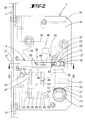
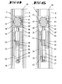
- the number 1 in Figure 1 denotes a door which is articulated by means of hinges 2 on a door frame 3.
- a drive rod lock 4 On the opposite side of the hinges 2, the door takes on a drive rod lock 4.
- the latter has a tfalz workede cuff 5 with it fixed main lock 6.
- a pawl lock additional lock 7 Above it is located on the cuff 5 designed as a pawl lock additional lock 7. That means that its locking bar 8 with a frame side hinged, longitudinally slotted locking bracket 9 cooperates.
- a pin latch lock 10 This corresponds in its construction to the bottom of the main lock 4 arranged pin lock 11th
- the main lock 4 is equipped with a latch 12 and a main latch 13. This is preferably two-speed by key operation forward and foundedsch. Along with a relocation of the Main latch 13 is displaced from the cuff 5 drive rod 14, which transfers their movement to the auxiliary lock 7 and the pin locks 10, 11.
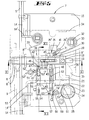
- the additional lock 7 has a lock bottom 15 connected to the cuff 5, parallel to which a lock cover 16 extends.
- a lock cover 16 extends in the space between the lock floor and lock cover 16 in the space between the lock floor and lock cover 16 in the Schlosßeinunde. Its bolt head 8 'passes through a cross-section adapted opening 17 of the cuff 5, while the bolt tail 8' 'by means of both sides projecting pin 18 in transverse slots 19, 20 of lock bottom 15 and lock cover 16 are performed. Downwardly directed, the locking bolt tail 8 "continues into a boom 21. This forms a parallel to the direction of displacement of the locking bolt 8 extending rack 22, which cooperates with the toothing 23 of a nut 24.
- FIG. 1 illustrates an internal operating handle 27, which is suitably connected to the nut 24.
- a helically coiled return spring 33 is attached, which loads the locking bolt 8 in Sch.einfacture.
- a driving rod connecting slide 34 is guided. This is coupled to the end portions 14 'of the divided at the level of the auxiliary lock 7 drive rod 14.
- the cuff 5 facing away from the drive rod connecting slide 34 has a wedge-shaped widening wedge slot 35 into which the pin 18 is immersed. The Vorsch twice the locking bolt 8 takes place via the oblique to the direction of exclusion of the locking bolt 8 extending inclined wall 35 ', which continues at the upper end in a niche 35' '.
- the driving rod connecting slide 34 On the side facing the cuff 5, the driving rod connecting slide 34 has a recess 36, which is separated from the wedge slot 35 by a narrow longitudinal web 37. At the longitudinal web 37 is a the locking bar 8 sleeve-shaped comprehensive slider 38 is supported. A spiral spring 39 acts on the slider 38 in the direction of the longitudinal web 37.
- the lever arm 29 'of the driving lever 29 terminates at a short distance in front of the rear edge of the slider 38, cf. the starting position in Figure 3.
- the other lever arm 29 '' of the driving lever 29 acts together with a lock bottom side stop 40th
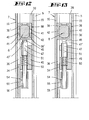
- the lock bottom 15 and the lock cover 16 facing broad side walls 38 'of the slider 38 each have a rearwardly open, extending in the longitudinal direction bolt longitudinal slot 41.
- the inner ends of the longitudinal slots 41 are formed to Aus confuseungsschrägen 42.
- Each Aus thoroughlyungsschräge 42 cooperates with the angled extending end 43 'of a leaf spring 43.
- Their width is slightly smaller than the width of the longitudinal slots 41.
- the leaf springs 43 are attached to both sides of the bar tail 8', on opposite sides of the same, see. Figure 10.
- Each leaf spring 43 carries a respective locking means 44 in the form of a locking pin. These locking means 44 dive into the longitudinal slots 41 of the slider 38 a. Due to the preload, the locking means 44 are pressed against the lock bottom 15 and lock cover 16.
- the locking means 44 cooperate with locking openings 45 in the lock bottom 15 and lock cover 16th
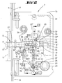
- the latter extends at Huaweiverlagertem locking bolt 8 between a first locking finger 47 and a second locking finger 48, which are guided transversely to the direction of movement of the locking bolt 8 in a secured to the lock bottom 15 housing 49.
- a compression spring 50 loads the rotationally secured first locking finger 47 in the direction of the locking bolt 8.
- At the upper end of the locking finger 47 forms a falling-like bevelled stop 47 'for cooperation with the locking projection 46.
- Radial directed goes from the first locking finger 47 a longitudinal slot of the housing 49 passing through driving pin 51, which cooperates with a rocker 52 mounted on the lock bottom.
- the one rocker arm 52 ' acts together with the driving pin 51, while the other rocker arm 52''according to Figure 3 is supported on a first projection 53 of the drive rod-connection slide 34.
- the protruding from the housing 49 lower end of the locking finger 47 carries a transverse pin 54, which passes through a longitudinal slot 55 of a plugged onto the lower end of the locking finger 47 shoe 56. The same passes through a slot 58 at the lower end of the locking finger 48.
- a tension spring 60 loads the trigger 59 in the counterclockwise direction such that the arm 59 'is supported on the coupling pin 57, cf. Figure 4.
- the second locking finger 48 secured in the housing 49 is loaded by a compression spring 62 in the direction of the slider 38 such that the upper end of the second locking finger 48 is supported on the underside of the slider 38, cf. in particular Figure 4.
- At the lower end of the second locking finger 48 has a projecting in the direction of the espagnolette cam cam 63 which cooperates with a arranged on the espagnolette slide 34 second projection 64.
- Figure 5 illustrates that the provided with an annular groove 8 '''bolt head 8' is engaged with the frame-side locking bracket 9, such that the locking bracket 9 and its slit at the height of the annular groove 8 '''extends.
Landscapes
- Engineering & Computer Science (AREA)
- Mechanical Engineering (AREA)
- Lock And Its Accessories (AREA)
- Preventing Unauthorised Actuation Of Valves (AREA)
- Saccharide Compounds (AREA)
- Polysaccharides And Polysaccharide Derivatives (AREA)
Claims (12)
- Serrure (4) à barres coulissantes avec une serrure principale (6) située côté battant, susceptible d'être actionnée par une clé, présentant un pêne principal (13), avec une barre coulissante (14) susceptible d'être déplacée le long d'une têtière (5) en actionnant la serrure principale (6), pour actionner un verrou (8) coopérant avec un étrier pivotant de blocage (9) situé du côté du châssis, d'une serrure auxiliaire (7) appartenant à la serrure à barres coulissantes, caractérisée en ce qu'après un actionnement de la serrure principale (6) dans la position de fermeture avec le verrou principal (13), le verrou (8) de la serrure auxiliaire (7) est verrouillé par l'actionnement de la barre coulissante et après un premier actionnement de déverrouillage de la serrure principale (6), le verrou principal (13) est déverrouillé tout comme le verrou (8) après un deuxième actionnement de déverrouillage.
- Serrure à barres coulissantes selon la revendication 1, caractérisée en ce qu'entre le premier et le deuxième actionnement de déverrouillage, le verrou principal (13) est de nouveau verrouillé.
- Serrure à barres coulissantes selon l'une des revendications précédentes, caractérisée par un couplage disposé plus particulièrement dans la serrure auxiliaire (7), qui découple le verrou (8) lors du premier actionnement de verrouillage lors de l'actionnement de la serrure.
- Serrure à barres coulissantes selon la revendication 3, caractérisée en ce que le couplage présente des moyens d'encliquetage (44, 45) qui maintiennent le verrou (8) en position verrouillée, ladite position d'encliquetage étant levée lors du second actionnement de déverrouillage.
- Serrure à barres coulissantes selon l'une des revendications précédentes, caractérisée par un premier doigt de blocage (47) qui maintient un coulisseau (38) disposé sur le verrou (8) dans une première position d'encliquetage, ledit doigt de blocage (47) étant retiré dans la première position de déverrouillage et libérant le coulisseau (38) pour qu'il se déplace dans une seconde position d'encliquetage dans laquelle le coulisseau (38) est maintenu par un second doigt de blocage (48) qui est retiré dans la position de nouveau verrouillée du verrou principal (13) et libère le coulisseau (38) pour lever l'encliquetage du verrou.
- Serrure à barres coulissantes selon l'une des revendications précédentes, caractérisée par un verrouillage commandé par la barre coulissante du verrou (8) dans une position d'encliquetage après un premier actionnement de déverrouillage de la serrure principale (6), position depuis laquelle le verrou (8) est rappelé de nouveau en position de déverrouillage par la force d'un ressort (33) de rappel en déverrouillage qui est précontraint lors du verrouillage, ce rappel déverrouillage intervenant lors de la libération de l'encliquetage commandé par la barre coulissante après un deuxième actionnement de déverrouillage de la serrure principale (6).
- Serrure à barres coulissantes selon l'une des revendications 4 à 6, caractérisée en ce que le verrou (8) est verrouillé lors d'un premier déplacement de la barre coulissante en position d'encliquetage, en ce qu'il est placé en position de libération lors d'un deuxième déplacement de la barre coulissante et en ce qu'il se verrouille de nouveau lors d'un troisième déplacement de la barre coulissante.
- Serrure à barres coulissantes selon l'une des revendications 5 à 7, caractérisée en ce que le coulisseau (38) est déplacé lors du premier actionnement de verrouillage au moyen d'un levier d'entraînement (29) disposé sur le verrou (8), ledit levier étant soulevé en phase finale de l'actionnement de verrouillage en une position de libération par rapport au coulisseau (38).
- Serrure à barres coulissantes selon l'une des revendications 5 à 8, caractérisée par une première saillie (53) disposée sur un coulisseau de raccordement (34) de la barre coulissante, qui déplace vers l'arrière le premier doigt de blocage (47) plus particulièrement via une bascule (52), et par une seconde saillie (64) disposée sur le coulisseau de raccordement de la barre coulissante (34) qui déplace vers l'arrière le second doigt de blocage (48) lors du deuxième actionnement de la barre coulissante.
- Serrure à barres coulissantes selon l'une des revendications précédentes, caractérisée en ce qu'afin d'actionner manuellement le verrou (8), celui-ci est couplé via une crémaillère (22) avec la denture (23) d'un fouillot (24) de la serrure auxiliaire (7).
- Serrure à barres coulissantes selon la revendication 10, caractérisée en ce que le fouillot (24) actionne lors de son actionnement de déverrouillage un déclencheur (59) pour déplacer en retour le deuxième doigt de blocage (48).
- Serrure à barres coulissantes selon l'une des revendications précédentes, caractérisée en ce que l'entrainement du verrou (8) en position de verrouillage est effectué via la paroi inclinée (35') d'une fente en coin (35) s'élargissant en forme de rampe.
Applications Claiming Priority (2)
| Application Number | Priority Date | Filing Date | Title |
|---|---|---|---|
| DE29602756U DE29602756U1 (de) | 1996-02-16 | 1996-02-16 | Treibstangenverschluß |
| DE29602756U | 1996-02-16 |
Publications (3)
| Publication Number | Publication Date |
|---|---|
| EP0790376A2 EP0790376A2 (fr) | 1997-08-20 |
| EP0790376A3 EP0790376A3 (fr) | 1997-08-27 |
| EP0790376B1 true EP0790376B1 (fr) | 2007-06-27 |
Family
ID=8019591
Family Applications (1)
| Application Number | Title | Priority Date | Filing Date |
|---|---|---|---|
| EP97101678A Expired - Lifetime EP0790376B1 (fr) | 1996-02-16 | 1997-02-04 | Serrure à Crémone |
Country Status (4)
| Country | Link |
|---|---|
| EP (1) | EP0790376B1 (fr) |
| AT (1) | ATE365856T1 (fr) |
| DE (2) | DE29602756U1 (fr) |
| ES (1) | ES2285717T3 (fr) |
Families Citing this family (1)
| Publication number | Priority date | Publication date | Assignee | Title |
|---|---|---|---|---|
| FR2825111B1 (fr) * | 2001-05-23 | 2004-01-30 | Ferco Int Usine Ferrures | Verrou entrebailleur de porte, fenetre ou analogue |
Family Cites Families (3)
| Publication number | Priority date | Publication date | Assignee | Title |
|---|---|---|---|---|
| AT366750B (de) * | 1980-11-13 | 1982-05-10 | Grundmann Rohrbacher Schlosser | Tuerverschluss |
| FR2576628B1 (fr) * | 1985-01-30 | 1989-06-30 | Grundmann Rohrbacher Schlosser | Fermeture de porte comprenant une serrure avec verrou et cremaillere et un element de verrouillage de securite relie a la serrure. |
| DE29509503U1 (de) * | 1995-06-14 | 1995-09-14 | Gretsch-Unitas GmbH Baubeschläge, 71254 Ditzingen | Mehrfachverriegelungsanlage |
-
1996
- 1996-02-16 DE DE29602756U patent/DE29602756U1/de not_active Expired - Lifetime
-
1997
- 1997-02-04 AT AT97101678T patent/ATE365856T1/de not_active IP Right Cessation
- 1997-02-04 EP EP97101678A patent/EP0790376B1/fr not_active Expired - Lifetime
- 1997-02-04 DE DE59712854T patent/DE59712854D1/de not_active Expired - Fee Related
- 1997-02-04 ES ES97101678T patent/ES2285717T3/es not_active Expired - Lifetime
Also Published As
| Publication number | Publication date |
|---|---|
| EP0790376A3 (fr) | 1997-08-27 |
| ATE365856T1 (de) | 2007-07-15 |
| DE59712854D1 (de) | 2007-08-09 |
| DE29602756U1 (de) | 1997-06-19 |
| EP0790376A2 (fr) | 1997-08-20 |
| ES2285717T3 (es) | 2007-11-16 |
Similar Documents
| Publication | Publication Date | Title |
|---|---|---|
| DE3836693C2 (de) | Treibstangenschloß | |
| EP2951369B1 (fr) | Serrure anti-panique | |
| DE3447748C2 (fr) | ||
| EP0796968B1 (fr) | Dispositif de fermeture | |
| DE102006059565A1 (de) | Schließanlage für Türen, Fenster oder dergleichen, insbesondere Treibstangenschloss mit Panikfunktion und Mehrpunktverriegelung | |
| DE3836694C2 (de) | Treibstangenschloß | |
| EP0413177A1 (fr) | Serrure pour bielle motrice | |
| EP1020597B1 (fr) | Serrure à crémone avec une serrure principal et une serrure complémentaire | |
| EP1020594B1 (fr) | Crémone | |
| EP1087084A2 (fr) | Serrure avec pêne demi-tour et pêne dormant et avec une longeur augmentée d'engrénage du pêne dormant | |
| EP0670403A2 (fr) | Serrure pour porte, notamment serrure encastrée | |
| DE2738746C3 (de) | Auslösevorrichtung für ein Paniktürschloß mit Falle und Riegel | |
| EP2072725A2 (fr) | Crémone-serrure | |
| DE4114007A1 (de) | Treibstangenverschluss | |
| EP2072723A2 (fr) | Crémone-serrure | |
| EP0790376B1 (fr) | Serrure à Crémone | |
| EP0496076B1 (fr) | Crémone-serrure | |
| EP0974721B1 (fr) | Serrure à plusieurs pênes | |
| DE19822951A1 (de) | Schloß mit Falle und Hilfsfalle | |
| EP0972900B1 (fr) | Crémone-serrure | |
| EP0990758A2 (fr) | Serrure additionelle pour crémone | |
| DE2605763C3 (de) | Treibstangenschloß mit Falle | |
| DE19756116B4 (de) | Treibstangenverschluß | |
| EP0795665A2 (fr) | Serrure encastrée | |
| DE19749023B4 (de) | Schloß für Türen, Fenster oder dergleichen |
Legal Events
| Date | Code | Title | Description |
|---|---|---|---|
| PUAI | Public reference made under article 153(3) epc to a published international application that has entered the european phase |
Free format text: ORIGINAL CODE: 0009012 |
|
| PUAL | Search report despatched |
Free format text: ORIGINAL CODE: 0009013 |
|
| AK | Designated contracting states |
Kind code of ref document: A2 Designated state(s): AT BE CH DE DK ES FR GB IE IT LI NL SE |
|
| AK | Designated contracting states |
Kind code of ref document: A3 Designated state(s): AT BE CH DE DK ES FR GB IE IT LI NL SE |
|
| 17P | Request for examination filed |
Effective date: 19971219 |
|
| GRAP | Despatch of communication of intention to grant a patent |
Free format text: ORIGINAL CODE: EPIDOSNIGR1 |
|
| GRAS | Grant fee paid |
Free format text: ORIGINAL CODE: EPIDOSNIGR3 |
|
| GRAA | (expected) grant |
Free format text: ORIGINAL CODE: 0009210 |
|
| RAP1 | Party data changed (applicant data changed or rights of an application transferred) |
Owner name: KFV KARL FLIETHER GMBH & CO. KG |
|
| AK | Designated contracting states |
Kind code of ref document: B1 Designated state(s): AT BE CH DE DK ES FR GB IE IT LI NL SE |
|
| REG | Reference to a national code |
Ref country code: GB Ref legal event code: FG4D Free format text: NOT ENGLISH |
|
| REG | Reference to a national code |
Ref country code: CH Ref legal event code: EP |
|
| REG | Reference to a national code |
Ref country code: IE Ref legal event code: FG4D Free format text: LANGUAGE OF EP DOCUMENT: GERMAN |
|
| REF | Corresponds to: |
Ref document number: 59712854 Country of ref document: DE Date of ref document: 20070809 Kind code of ref document: P |
|
| GBT | Gb: translation of ep patent filed (gb section 77(6)(a)/1977) |
Effective date: 20070831 |
|
| PG25 | Lapsed in a contracting state [announced via postgrant information from national office to epo] |
Ref country code: SE Free format text: LAPSE BECAUSE OF FAILURE TO SUBMIT A TRANSLATION OF THE DESCRIPTION OR TO PAY THE FEE WITHIN THE PRESCRIBED TIME-LIMIT Effective date: 20070927 |
|
| REG | Reference to a national code |
Ref country code: CH Ref legal event code: NV Representative=s name: R. A. EGLI & CO. PATENTANWAELTE |
|
| ET | Fr: translation filed | ||
| REG | Reference to a national code |
Ref country code: ES Ref legal event code: FG2A Ref document number: 2285717 Country of ref document: ES Kind code of ref document: T3 |
|
| REG | Reference to a national code |
Ref country code: IE Ref legal event code: FD4D |
|
| PG25 | Lapsed in a contracting state [announced via postgrant information from national office to epo] |
Ref country code: IE Free format text: LAPSE BECAUSE OF FAILURE TO SUBMIT A TRANSLATION OF THE DESCRIPTION OR TO PAY THE FEE WITHIN THE PRESCRIBED TIME-LIMIT Effective date: 20070627 |
|
| PG25 | Lapsed in a contracting state [announced via postgrant information from national office to epo] |
Ref country code: DK Free format text: LAPSE BECAUSE OF FAILURE TO SUBMIT A TRANSLATION OF THE DESCRIPTION OR TO PAY THE FEE WITHIN THE PRESCRIBED TIME-LIMIT Effective date: 20070627 |
|
| PLBE | No opposition filed within time limit |
Free format text: ORIGINAL CODE: 0009261 |
|
| STAA | Information on the status of an ep patent application or granted ep patent |
Free format text: STATUS: NO OPPOSITION FILED WITHIN TIME LIMIT |
|
| 26N | No opposition filed |
Effective date: 20080328 |
|
| BERE | Be: lapsed |
Owner name: KFV KARL FLIETHER G.M.B.H. & CO. KG Effective date: 20080228 |
|
| REG | Reference to a national code |
Ref country code: CH Ref legal event code: PL |
|
| GBPC | Gb: european patent ceased through non-payment of renewal fee |
Effective date: 20080204 |
|
| PG25 | Lapsed in a contracting state [announced via postgrant information from national office to epo] |
Ref country code: LI Free format text: LAPSE BECAUSE OF NON-PAYMENT OF DUE FEES Effective date: 20080229 Ref country code: CH Free format text: LAPSE BECAUSE OF NON-PAYMENT OF DUE FEES Effective date: 20080229 |
|
| NLV4 | Nl: lapsed or anulled due to non-payment of the annual fee |
Effective date: 20080901 |
|
| PG25 | Lapsed in a contracting state [announced via postgrant information from national office to epo] |
Ref country code: NL Free format text: LAPSE BECAUSE OF NON-PAYMENT OF DUE FEES Effective date: 20080901 |
|
| REG | Reference to a national code |
Ref country code: FR Ref legal event code: ST Effective date: 20081031 |
|
| PG25 | Lapsed in a contracting state [announced via postgrant information from national office to epo] |
Ref country code: DE Free format text: LAPSE BECAUSE OF NON-PAYMENT OF DUE FEES Effective date: 20080902 |
|
| PG25 | Lapsed in a contracting state [announced via postgrant information from national office to epo] |
Ref country code: BE Free format text: LAPSE BECAUSE OF NON-PAYMENT OF DUE FEES Effective date: 20080228 |
|
| PG25 | Lapsed in a contracting state [announced via postgrant information from national office to epo] |
Ref country code: FR Free format text: LAPSE BECAUSE OF NON-PAYMENT OF DUE FEES Effective date: 20080229 Ref country code: AT Free format text: LAPSE BECAUSE OF NON-PAYMENT OF DUE FEES Effective date: 20080204 |
|
| REG | Reference to a national code |
Ref country code: ES Ref legal event code: FD2A Effective date: 20080205 |
|
| PG25 | Lapsed in a contracting state [announced via postgrant information from national office to epo] |
Ref country code: GB Free format text: LAPSE BECAUSE OF NON-PAYMENT OF DUE FEES Effective date: 20080204 |
|
| PG25 | Lapsed in a contracting state [announced via postgrant information from national office to epo] |
Ref country code: ES Free format text: LAPSE BECAUSE OF NON-PAYMENT OF DUE FEES Effective date: 20080205 |
|
| PG25 | Lapsed in a contracting state [announced via postgrant information from national office to epo] |
Ref country code: IT Free format text: LAPSE BECAUSE OF NON-PAYMENT OF DUE FEES Effective date: 20080204 |