EP0712987B2 - Lock, in particular espagnolette with bipartite handle follower - Google Patents
Lock, in particular espagnolette with bipartite handle follower Download PDFInfo
- Publication number
- EP0712987B2 EP0712987B2 EP95114646A EP95114646A EP0712987B2 EP 0712987 B2 EP0712987 B2 EP 0712987B2 EP 95114646 A EP95114646 A EP 95114646A EP 95114646 A EP95114646 A EP 95114646A EP 0712987 B2 EP0712987 B2 EP 0712987B2
- Authority
- EP
- European Patent Office
- Prior art keywords
- follower
- lock according
- halves
- actuating
- lock
- Prior art date
- Legal status (The legal status is an assumption and is not a legal conclusion. Google has not performed a legal analysis and makes no representation as to the accuracy of the status listed.)
- Expired - Lifetime
Links
- 230000008878 coupling Effects 0.000 claims description 33
- 238000010168 coupling process Methods 0.000 claims description 33
- 238000005859 coupling reaction Methods 0.000 claims description 33
- 230000007935 neutral effect Effects 0.000 claims description 12
- 230000000903 blocking effect Effects 0.000 claims description 8
- 230000015572 biosynthetic process Effects 0.000 claims 1
- 238000006073 displacement reaction Methods 0.000 description 3
- 230000006835 compression Effects 0.000 description 2
- 238000007906 compression Methods 0.000 description 2
- 238000011161 development Methods 0.000 description 2
- 230000018109 developmental process Effects 0.000 description 2
- 230000007717 exclusion Effects 0.000 description 2
- DCRGHMJXEBSRQG-UHFFFAOYSA-N 1-[1-(cyclooctylmethyl)-5-(hydroxymethyl)-3,6-dihydro-2H-pyridin-4-yl]-3-ethyl-2-benzimidazolone Chemical compound O=C1N(CC)C2=CC=CC=C2N1C(CC1)=C(CO)CN1CC1CCCCCCC1 DCRGHMJXEBSRQG-UHFFFAOYSA-N 0.000 description 1
- 230000000881 depressing effect Effects 0.000 description 1
- 230000000994 depressogenic effect Effects 0.000 description 1
- 230000003993 interaction Effects 0.000 description 1
- 230000002441 reversible effect Effects 0.000 description 1
- 238000000926 separation method Methods 0.000 description 1
- 230000004936 stimulating effect Effects 0.000 description 1
Images


Classifications
-
- E—FIXED CONSTRUCTIONS
- E05—LOCKS; KEYS; WINDOW OR DOOR FITTINGS; SAFES
- E05C—BOLTS OR FASTENING DEVICES FOR WINGS, SPECIALLY FOR DOORS OR WINDOWS
- E05C9/00—Arrangements of simultaneously actuated bolts or other securing devices at well-separated positions on the same wing
- E05C9/02—Arrangements of simultaneously actuated bolts or other securing devices at well-separated positions on the same wing with one sliding bar for fastening when moved in one direction and unfastening when moved in opposite direction; with two sliding bars moved in the same direction when fastening or unfastening
- E05C9/025—Arrangements of simultaneously actuated bolts or other securing devices at well-separated positions on the same wing with one sliding bar for fastening when moved in one direction and unfastening when moved in opposite direction; with two sliding bars moved in the same direction when fastening or unfastening with pins engaging slots
-
- E—FIXED CONSTRUCTIONS
- E05—LOCKS; KEYS; WINDOW OR DOOR FITTINGS; SAFES
- E05B—LOCKS; ACCESSORIES THEREFOR; HANDCUFFS
- E05B63/00—Locks or fastenings with special structural characteristics
- E05B63/04—Locks or fastenings with special structural characteristics for alternative use on the right-hand or left-hand side of wings
- E05B63/042—Locks or fastenings with special structural characteristics for alternative use on the right-hand or left-hand side of wings constructed symmetrically
-
- E—FIXED CONSTRUCTIONS
- E05—LOCKS; KEYS; WINDOW OR DOOR FITTINGS; SAFES
- E05C—BOLTS OR FASTENING DEVICES FOR WINGS, SPECIALLY FOR DOORS OR WINDOWS
- E05C9/00—Arrangements of simultaneously actuated bolts or other securing devices at well-separated positions on the same wing
- E05C9/02—Arrangements of simultaneously actuated bolts or other securing devices at well-separated positions on the same wing with one sliding bar for fastening when moved in one direction and unfastening when moved in opposite direction; with two sliding bars moved in the same direction when fastening or unfastening
- E05C9/026—Arrangements of simultaneously actuated bolts or other securing devices at well-separated positions on the same wing with one sliding bar for fastening when moved in one direction and unfastening when moved in opposite direction; with two sliding bars moved in the same direction when fastening or unfastening comprising key-operated locks, e.g. a lock cylinder to drive auxiliary deadbolts or latch bolts
-
- E—FIXED CONSTRUCTIONS
- E05—LOCKS; KEYS; WINDOW OR DOOR FITTINGS; SAFES
- E05B—LOCKS; ACCESSORIES THEREFOR; HANDCUFFS
- E05B15/00—Other details of locks; Parts for engagement by bolts of fastening devices
- E05B15/0033—Spindles for handles, e.g. square spindles
-
- E—FIXED CONSTRUCTIONS
- E05—LOCKS; KEYS; WINDOW OR DOOR FITTINGS; SAFES
- E05B—LOCKS; ACCESSORIES THEREFOR; HANDCUFFS
- E05B59/00—Locks with latches separate from the lock-bolts or with a plurality of latches or lock-bolts
-
- E—FIXED CONSTRUCTIONS
- E05—LOCKS; KEYS; WINDOW OR DOOR FITTINGS; SAFES
- E05B—LOCKS; ACCESSORIES THEREFOR; HANDCUFFS
- E05B63/00—Locks or fastenings with special structural characteristics
- E05B63/16—Locks or fastenings with special structural characteristics with the handles on opposite sides moving independently
Definitions
- the invention relates to a lock, in particular espagnolette lock according to Generic term of claim 1.
- EP 0 620 341 A1 and the associated DE 694 08 012 T2 describe one such espagnolette lock.
- the nut has two nut halves, the either with one from one or the other side of the nut a central arm can be coupled. This arm grips a ledge a trap to withdraw the trap.
- the espagnolette lock disclosed there has one consisting of two halves Trigger nut on.
- the halves are in the axial direction to each other, with each half a trigger pin assigned is.
- a push pin especially the inner one Trigger mandrel, can be activated by pressing the trigger Withdraw the trap. To do this, it points to the inner handle associated nut half an arm that with a Actuating projection of the trap interacts.
- the both pusher halves are the same as the two Turning the nut halves so that the actuation of the Inside handle or the outside handle the opposite other pusher or this pusher assigned nut half leaves unaffected.
- known lock is the trap only by pressing the inner half of the nut retractable.
- An actuation of the outer half of the nut has no trap retraction.
- Both nut halves can also be turned in the opposite direction. When the pushers are actuated in the opposite direction there is a relocation of an im Lock case arranged drive rod.
- the invention is therefore based on the object a generic lock useful further education.
- the configuration according to the invention is a lock, especially espagnolette lock given, with which a simple means Left / right changeover is possible.
- the mirror symmetry trained nut halves can either the one, the other or both of the nut halves coupled to the trap become.
- the coupling links are detachable and therefore relocatable even after the lock has been manufactured or reversible, so that the coupling between Trap and nut is adjustable.
- the trap is preferred assigned an actuating section on the tail side.
- This actuating section can be designed as a projection his. It is further preferred that the lock be a Change lever is assigned, which on this operating section acts. In a preferred further training the invention provides that the nut actuation is locked when the bolt is locked. It is also conceivable, instead of the nut relocability to lock the connecting rod connecting slide. For this can a protruding into the actuation path of the nut Locking element can be provided, which is a locking slide assigned.
- the gate valve can be together with the bolt exclusion in Deadbolt movement be shifted.
- the Gate valve preferably has two fork-shaped arranged Locking tines on, each locking tine with a locking projection of one of the two nut halves cooperates. Each nut preferably has an actuating arm on.
- the two operating arms should in the axial direction (pusher mandrel axis) from each other be spaced so that between the two arms there is a gap. In this space can at the turn of the nut the operating section of the trap tail protrude.
- the coupling member can either the trap tail or the nut arm be assigned.
- the coupling link is the nut arm assigned, it is preferably provided that it is in the Clearance space protrudes, so that when the nut rotates the coupling member the operating section of the trap tail acted upon and thereby pulls back the trap.
- the coupling piece is the trap tail assigned, it is preferably in the region of the actuating section arranged and protrudes in the axial direction in the path of movement of one or both nut arms.
- each half of the nut is sprung individually Held in the middle position.
- the sprung middle position can be maintained by a two-armed slide be, as in DE-OS 40 41 537 is described in detail. It is preferred that one such spring-loaded slide is provided twice, each slider separately on one of the two nut halves acts. Both nut halves have a radial one Edge recess in which a tooth a Swing lever protrudes. The opening of the radial recess is much larger than the effective thickness of the Tooth, so that there is nut clearance.
- Such one Access is also in OS 40 41 537 in Described in detail and serves to ensure that after a Espagnolette displacement either in the open or in the locking position the nut back to the neutral position is returned. Between the two edge areas, which the radial recess is assigned to a clearance is also provided, in which a portion of the pivot lever protrudes. Each in Two teeth protrude from this section of the swivel lever.
- a further development of the invention provides that the coupling member is not the operating arm is assigned to the two nut halves, but that Catch tail.
- the coupling member is preferably the actuating section of the trap tail assigned and displaceable in the transverse direction to the castle level.
- the displaceability of the coupling member can be done by a spindle drive, which is in the form a screw rotatably arranged in the trap tail is trained.
- the spindle drive can have a Screwdriver.
- the spindle is supported at both ends in the operating section, so that a narrow actuator in a space is displaceable in the transverse direction that it is in one extreme position by an operating arm one half of the nut can be loaded, but not from the other and in the other extreme position acted upon by the other half of the nut is, in which case the other half of the nut is released.
- the functioning of the lock corresponds essentially that of the castle according to the OS 40 41 537.
- the design is also shared there described.
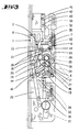
- the lock according to the invention has one Lock case on which a lock floor 35 and has a lock cover 34. This is indicated on the front Unlocked a cuff with openings through which a latch head 8 a latch 1 and a bolt 29 step through. Along the cuff is in the lock case a connecting rod connecting slide 22 guided.
- a pivot lever 19 which has a first arm in which a slot 20 is provided; in the latter protrudes a pin 21.
- the pin 21 is with the Espagnolette connecting slide 22 connected.
- the pivot lever 19 has two axially opposite Pins or teeth 18 on, which by a portion 44 are separated.
- the two pins 18 protrude into a radial recess 17 of the two nut halves 5, 6 a.
- the radial recess 17 has such a circumferential angular width that each of the two nut halves 5, 6 held in the neutral position regardless of the position of the Swivel lever 19 between its two end positions (Fig. 1, Fig. 2).
- the neutral position of the two nut halves 5, 6 is in each case by a sprung slide 14, 36 maintained.
- the slide 14, 36 has two Slider arms 15, which with drivers 16 of the Nut work together.
- OS 40 41 537 In terms of interaction of slides 14, 36 with the drivers 16 of the both nut halves are referred to OS 40 41 537.
- a bolt 29 is provided in the lock housing, which by actuating a profile locking cylinder is lockable and lockable.
- the lock cylinder has a closing member 31, which with a tumbler 30 interacts. There is one on the bar Exchange lever stored, which of the Locking member 31 can be acted upon.
- the second arm of the Kirs 31 acts on an operating section 7 of the trap tail 2 so that when changing the trap 1 is withdrawn.
- the espagnolette lock has two in the axial direction the lever axis one behind the other Nut halves 5 and 6.
- the nut halves 5, 6 are symmetrical and each have an arm 10 on.
- the arms 10 are at least in the area of their free Ends spaced. Forms between the trap arms a space in which a stop 9 of the actuating section 7 of the case 1 protrudes.
- Everyone who both arms 10 has a bore into which one Coupling pin can be inserted.
- 6 is the coupling pin 11 in the right nut half 6 and in Fig. 7 the coupling pin 11 is inserted into the left nut half 5. Accordingly, the traps are withdrawn in accordance with 6 when the handle 4 is actuated and according to FIG. 7 when pressing the trigger 3.
- the two nut halves 5, 6 are not entrained in rotation, but rather can be rotated against each other without turning entrainment become.
- the two trigger mandrel sections 3.4 can be rotated against each other.
- the Stimulating the two axially aligned to each other Mandrel sections 3, 4 are spaced apart. They lie in a blind hole 23 with a rectangular cross section the respective nut half 5, 6 a.
- It is a coupling pin 38 is provided which consists of one of the protrudes both ends of the pusher dome 4 and in the opposite end face of the trigger mandrel section 3 protrudes. The pin is designed so round that the two pushers 3, 4 against each other can be twisted.
- the mirror-symmetrical Nut halves 5,6 slide with one of their end faces each other. Point opposite the end faces the nut halves 5, 6 on a cylindrical collar, which in a corresponding opening of Castle cover 34 or castle floor 35 is inserted. It is provided that in both arms 10 of the two nut halves 5, 6 a coupling pin 11 can be inserted.
- the coupling pin 11 extends up to the level of the parting line the two halves of the nut in the space. It sticks out especially in the space between the two free ends of the arms 10. In the plane of the parting line is a section 9 of the trap, which the releasable Coupling member 11 acted upon nut actuation.
- driver projections 16 On the opposite of the parting line
- the end face of the nut 5, 6 are driver projections 16 arranged, on each of which a prong 15, 37 one Slider 14 rests.
- the drivers 16 are approximately diametrical arranged opposite, so that depending on Direction of rotation of the slider nut along with a compression of the spring 32, 33 is shifted.
- the the two springs 32, 33 are in alignment with one another Lock case arranged and act on the Slider 14, 36 elastic.
- a gate valve 27 is arranged.
- the gate valve 27 has two parallel tines 45, 46, wherein each tine 45, 46 is provided with a spermase 25, which interacts with a locking projection 26 of the nut.
- the locking lug 25 undermines the locking projection 26 when the slide 27 in Bolt exclusion direction is shifted. This can the pusher 24 can no longer be depressed to to move the drive rod into the open position.
- the trap head 8 only needs 180 ° be rotated.
- a cylindrical trap tail 2 provided, which with a screw 39 in a trap end piece, which is from the operating section 7 is formed, is attached to the latter. Loosening the screw 39 enables turning the trap 8.
- the pin 11 from the Nut half 6 are pulled out and (as in Fig. 7 shown) are inserted into the nut half 5. Then the nut half 6 is uncoupled from the trap.
- the coupling member 47 is the trap tail, namely assigned to the actuating section 107.
- the actuating section 107 has one U-shaped recess in which a plate lies, which with an end portion 47 'of the latch arm 110 can be acted upon.
- the plate 47 has approximately a thickness that corresponds to half of the U-space.
- a Rotation of screw 48 does not cause displacement the screw opposite the operating section 107.
- the coupling member 47 has an internal thread into which the external thread of the screw 48 protrudes. The screw 48 thus acts as a threaded spindle.
- the Coupling member 47 transverse to the lock extension plane shift so that it is either from the actuating arm 110 the nut half 106 or the actuating arm 110 'of Nut half 105 can be applied.
- the each the other half of the nut is then released without the latch being actuated becomes.
- the Nut halves parallel to each other in such a way that the two Actuating arms 110, 110 'separated by a free space are. This enables a clean separation of movements by transverse displacement of the coupling member 47th
- the trap tail 102 of the trap 101 has one Pocket 49 in which an end portion of a Exchange lever 113 immersed.
- the trap tail 102 continues towards the rear into an operating section 107, which has the recess in which the coupling member 47 is displaceable transversely is.
- the two nut halves 105, 106 are in their neutral center position by a slide 114 held, which is acted upon by a compression spring 133 becomes.
- the slider 114 has two fork tines 15 on the corresponding driver 16 of the Soak in the nut halves.
Landscapes
- Engineering & Computer Science (AREA)
- Mechanical Engineering (AREA)
- Structural Engineering (AREA)
- Lock And Its Accessories (AREA)
- Arrangement Or Mounting Of Control Devices For Change-Speed Gearing (AREA)
- Pharmaceuticals Containing Other Organic And Inorganic Compounds (AREA)
- Press Drives And Press Lines (AREA)
- Mechanical Control Devices (AREA)
- Preventing Unauthorised Actuation Of Valves (AREA)
- Automatic Assembly (AREA)
Abstract
Description
Die Erfindung betrifft ein Schloß, insbesondere Treibstangenschloß gemäß
Gattungsbegriff des Anspruches 1.The invention relates to a lock, in particular espagnolette lock according to
Generic term of
Die EP 0 620 341 A1 bzw. die zugehörige DE 694 08 012 T2 beschreibt ein derartiges Treibstangenschloß. Dort besitzt die Nuß zwei Nußhälften, die wahlweise mittels einer von der einen oder von der anderen Nußseite her mit einem zentralen Arm kuppelbar ist. Dieser Arm greift an einem Vorsprung einer Falle an, um die Falle zurückzuziehen.EP 0 620 341 A1 and the associated DE 694 08 012 T2 describe one such espagnolette lock. There the nut has two nut halves, the either with one from one or the other side of the nut a central arm can be coupled. This arm grips a ledge a trap to withdraw the trap.
Eine ähnliche Lösung zeigt die EP 0 537 531. Auch bei diesem Türschloß sind zwei im Schloßkasten schwenkverstellbar gelagerte Schloßnußteile vorgesehen für eine unabhängige Innen- und Außenbetätigung des Schlosses. Die beiden Nußteile sind über einen Kupplungsstift mit einem koaxial zu den Nußteilen gelagerten Winkelhebel kuppelbar. Der Winkelhebel greift an einem rückwärtigen Abschnitt der Falle an, um sie bei Verschwenken der Nuß zurückzuziehen.A similar solution is shown in EP 0 537 531. Also in this door lock two lock nut parts pivotally mounted in the lock case are provided for independent internal and external operation of the lock. The two Nut parts are coaxial with the nut parts via a coupling pin mounted angle lever can be coupled. The angle lever grips one rear section of the trap to hold it when pivoting the nut withdraw.
Ein weiteres Treibstangenschloß ist aus der DE-OS 28 45 957 bekannt.Another espagnolette lock is known from DE-OS 28 45 957.
Das dort offenbarte Treibstangenschloß weist eine aus zwei Hälften bestehende Drückernuß auf. Die Hälften liegen in Achsrichtung zueinander, wobei jeder Hälfte ein Drückerdorn zugeordnet ist. Mit einem Drückerdorn, insbesondere dem inneren Drückerdorn, läßt sich durch Drückerbetätigung die Falle zurückziehen. Hierzu weist die dem inneren Drükker zugeordnete Nußhälfte einen Arm auf, der mit einem Betätigungsvorsprung der Falle zusammenwirkt. Die beiden Drückerhälften sind ebenso wie die beiden Nußhälften drehentkuppelt, so daß die Betätigung des Innendrückers bzw. des Außendrückers den gegenüberliegenden anderen Drücker bzw. die diesem Drükker zugeordnete Nußhälfte unbeeinflußt läßt. Bei dem bekannten Schloß ist die Falle nur durch Betätigung der inneren Nußhälfte zurückziehbar. Eine Betätigung der äußeren Nußhälfte hat keinen Fallenrückzug zur Folge. Beide Nußhälften sind dort auch in Gegenrichtung verdrehbar. Bei einer Betätigung der Drücker in diese Gegenrichtung erfolgt eine Verlagerung einer im Schloßkasten angeordneten Treibstange.The espagnolette lock disclosed there has one consisting of two halves Trigger nut on. The halves are in the axial direction to each other, with each half a trigger pin assigned is. With a push pin, especially the inner one Trigger mandrel, can be activated by pressing the trigger Withdraw the trap. To do this, it points to the inner handle associated nut half an arm that with a Actuating projection of the trap interacts. The both pusher halves are the same as the two Turning the nut halves so that the actuation of the Inside handle or the outside handle the opposite other pusher or this pusher assigned nut half leaves unaffected. In which known lock is the trap only by pressing the inner half of the nut retractable. An actuation of the outer half of the nut has no trap retraction. Both nut halves can also be turned in the opposite direction. When the pushers are actuated in the opposite direction there is a relocation of an im Lock case arranged drive rod.
Ein aus zwei Drückerhälften bestehendes Schloß ist ebenfalls aus der DE-PS 40 26 080 bekannt.One consisting of two handle halves Castle is also known from DE-PS 40 26 080.
Ein Treibstangenschloß mit Innen- und Außendrücker,
bei welchem die Drückerbetätigung in die eine
Richtung einen Fallenrückzug zur Folge hat und eine
Drückerbetätigung in die Gegenrichtung die Verlagerung
einer Treibstange bewirkt, ist aus der DE-OS 40
41 537 bekannt.An espagnolette lock with inside and outside handle,
in which the trigger actuation in one
Direction results in a trap retreat and one
Lever actuation in the opposite direction
causes a connecting rod is from DE-OS
Nachteilhaft an dem eingangs genannten Schloß ist die nur beschränkte Verwendbarkeit. Ein derartiges Schloß kann bauartbedingt entweder nur für links- oder rechtsangeschlagene Türen verwendet werden.A disadvantage of the above Castle is only of limited use. Such a thing Due to its design, the lock can only be used for left or right hinged doors can be used.
Der Erfindung liegt daher die Aufgabe zugrunde, ein gattungsgemäßes Schloß gebrauchsvorteilhaft weiterzubilden.The invention is therefore based on the object a generic lock useful further education.
Gelöst wird die Aufgabe durch die im Anspruch
1 angegebene Erfindung.The task is solved by the
Unteransprüche stellen vorteilhafte Weiterbildungen der Erfindung dar.Subclaims represent advantageous further developments of the invention.
Zufolge der erfindungsgemäßen Ausgestaltung ist ein Schloß, insbesondere Treibstangenschloß gegeben, bei welchem mit einfachen Mitteln eine Links-/Rechtsumstellung möglich ist. Zufolge der spiegelsymmetrisch ausgebildeten Nußhälften kann entweder die eine, die andere oder beide Nußhälften mit der Falle gekuppelt werden. Die Kupplungsglieder sind lösbar und daher auch nach der Fertigung des Schlosses verlagerbar bzw. umsteckbar, so daß die Kupplung zwischen Falle und Nuß einstellbar ist. Der Falle ist bevorzugt schwanzseitig ein Betätigungsabschnitt zugeordnet.As a result of the configuration according to the invention is a lock, especially espagnolette lock given, with which a simple means Left / right changeover is possible. As a result of the mirror symmetry trained nut halves can either the one, the other or both of the nut halves coupled to the trap become. The coupling links are detachable and therefore relocatable even after the lock has been manufactured or reversible, so that the coupling between Trap and nut is adjustable. The trap is preferred assigned an actuating section on the tail side.
Dieser Betätigungsabschnitt kann als Vorsprung ausgebildet
sein. Es ist weiter bevorzugt, daß dem Schloß ein
Wechselhebel zugeordnet ist, welcher auf diesen Betätigungsabschnitt
wirkt. In einer bevorzugten Weiterbildung
der Erfindung ist vorgesehen, daß die Nußbetätigung
bei vorgeschlossenem Riegel gesperrt ist. Es ist
ebenfalls denkbar, anstelle der Nuß die Verlagerbarkeit
des Treibstangenanschlußschiebers zu sperren. Hierzu
kann ein in den Betätigungsweg der Nuß ragendes
Sperrglied vorgesehen sein, welches einem Sperrschieber
zugeordnet ist. Der Sperrschieber kann zusammen
mit dem Riegelausschluß in
Riegelvorschlußbewegung verlagert werden. Der
Sperrschieber weist bevorzugt zwei gabelförmig angeordnete
Sperrzinken auf, wobei jeder Sperrzinken mit
einem Sperrvorsprung einer der beiden Nußhälften zusammenwirkt.
Jede Nuß weist bevorzugt einen Betätigungsarm
auf. Dabei sollen die beiden Betätigungsarme
in Achsrichtung (Drückerdornachse) voneinander
beabstandet sein, so daß zwischen den beiden Armen
ein Zwischenraum besteht. In diesen Abstandsraum
kann bei Nußdrehung der Betätigungsabschnitt des Fallenschwanzes
ragen. Das Kupplungsglied kann entweder
dem Fallenschwanz oder aber auch dem Nußarm
zugeordnet sein. Ist das Kupplungsglied dem Nußarm
zugeordnet, so ist bevorzugt vorgesehen, daß es in den
Abstandsraum ragt, so daß bei einer Drehung der Nuß
das Kupplungsglied den Betätigungsabschnitt des Fallenschwanzes
beaufschlagt und dadurch die Falle zurückzieht.
Ist das Kupplungsstück dem Fallenschwanz
zugeordnet, so ist es bevorzugt im Bereich des Betätigungsabschnittes
angeordnet und ragt in Achsrichtung
in die Bewegungsbahn eines oder beider Nußarme. Bevorzugt
wird jede Nußhälfte jeweils für sich in einer abgefederten
Mittelstellung gehalten. Die abgefederte Mittelstellung
kann durch einen zweiarmigen Schieber aufrechterhalten
werden, wie es in der DE-OS 40 41 537
im Detail beschrieben ist. Es ist bevorzugt, daß ein derartig
abgefederter Schieber zweimal vorgesehen ist,
wobei jeder Schieber separat auf eine der beiden Nußhälften
wirkt. Beide Nußhälften weisen jeweils eine radiale
Randaussparung auf, in welche ein Zahn eines
Schwenkhebels ragt. Die Öffnung der Radialaussparung
ist wesentlich größer als die wirksame Dicke des
Zahnes, so daß ein Nußfreigang gegeben ist. Ein derartiger
Freigang ist ebenfalls in der OS 40 41 537 im
Detail beschrieben und dient dazu, daß nach einer
Treibstangenverlagerung entweder in die Offen- oder in
die Sperrstellung die Nuß wieder in die Neutralstellung
zurückgeführt wird. Zwischen den beiden Randbereichen,
welchen die Radialaussparung zugeordnet ist, ist
ebenfalls ein Abstandsfreiraum vorgesehen, in welchen
ein Teilabschnitt des Schwenkhebels ragt. Jeweils in
Achsrichtung ragen aus diesem Teilabschnitt zwei Zähne
des Schwenkhebels.This actuating section can be designed as a projection
his. It is further preferred that the lock be a
Change lever is assigned, which on this operating section
acts. In a preferred further training
the invention provides that the nut actuation
is locked when the bolt is locked. It is
also conceivable, instead of the nut relocability
to lock the connecting rod connecting slide. For this
can a protruding into the actuation path of the nut
Locking element can be provided, which is a locking slide
assigned. The gate valve can be together
with the bolt exclusion in
Deadbolt movement be shifted. The
Gate valve preferably has two fork-shaped arranged
Locking tines on, each locking tine with
a locking projection of one of the two nut halves cooperates.
Each nut preferably has an actuating arm
on. The two operating arms should
in the axial direction (pusher mandrel axis) from each other
be spaced so that between the two arms
there is a gap. In this space
can at the turn of the nut the operating section of the trap tail
protrude. The coupling member can either
the trap tail or the nut arm
be assigned. The coupling link is the nut arm
assigned, it is preferably provided that it is in the
Clearance space protrudes, so that when the nut rotates
the coupling member the operating section of the trap tail
acted upon and thereby pulls back the trap.
The coupling piece is the trap tail
assigned, it is preferably in the region of the actuating section
arranged and protrudes in the axial direction
in the path of movement of one or both nut arms. Prefers
each half of the nut is sprung individually
Held in the middle position. The sprung middle position
can be maintained by a two-armed slide
be, as in DE-OS 40 41 537
is described in detail. It is preferred that one such
spring-loaded slide is provided twice,
each slider separately on one of the two nut halves
acts. Both nut halves have a radial one
Edge recess in which a tooth a
Swing lever protrudes. The opening of the radial recess
is much larger than the effective thickness of the
Tooth, so that there is nut clearance. Such one
Access is also in
Eine Weiterbildung der Erfindung sieht vor, daß das Kupplungsglied nicht dem Betätigungsarm einer der beiden Nußhälften zugeordnet ist, sondern dem Fallenschwanz. Vorzugsweise ist das Kupplungsglied dabei dem betätigungsabschnitt des Fallenschwanzes zugeordnet und in Querrichtung zur Schloßebene verlagerbar. Die Verlagerbarkeit des Kupplungsgliedes kann durch einen Spindeltrieb erfolgen, welcher in Form einer im Fallenschwanz drehbar angeordneten Schraube ausgebildet ist. Der Spindeltrieb kann dabei über einen Schraubendreher betätigt werden. Die Spindel ist an ihren beiden Enden im Betätigungsabschnitt gelagert, so daß in einem Zwischenraum ein schmales Betätigungsglied in Querrichtung verlagerbar ist derart, daß es in der einen Extremstellung von einem Betätigungsarm der einen Nußhälfte beaufschlagbar ist, aber nicht von der anderen und in der anderen Extremstellung von der jeweils anderen Nußhälfte beaufschlagbar ist, wobei dann die jeweils andere Nußhälfte freigeht.A further development of the invention provides that the coupling member is not the operating arm is assigned to the two nut halves, but that Catch tail. The coupling member is preferably the actuating section of the trap tail assigned and displaceable in the transverse direction to the castle level. The displaceability of the coupling member can be done by a spindle drive, which is in the form a screw rotatably arranged in the trap tail is trained. The spindle drive can have a Screwdriver. The spindle is supported at both ends in the operating section, so that a narrow actuator in a space is displaceable in the transverse direction that it is in one extreme position by an operating arm one half of the nut can be loaded, but not from the other and in the other extreme position acted upon by the other half of the nut is, in which case the other half of the nut is released.
Nachfolgend wird anhand von beigefügten Zeichnungen ein Ausführungsbeispiel der Erfindung erläutert. Es zeigen
- Fig. 1
- ein Treibstangenschloß mit geöffnetem Dekkel in der Neutralstellung bei zurückgezogenem Riegel,
- Fig. 2
- eine Darstellung gemäß Fig. 1 bei in die Sperrstellung verlagerter Treibstange und aus der Neutralstellung gebrachter Nußhälfte,
- Fig. 3
- eine Darstellung gemäß Fig. 1 mit in die Öffnungsstellung verlagertem TreibstangenAnschlußschieber und entsprechend aus der Neutralstellung verlagerter Nußhälfte,
- Fig. 4
- eine Darstellung gemäß Fig. 1 bei zurückgezogener Falle zufolge Wechselbetätigung,
- Fig. 5
- eine Darstellung gemäß Fig. 1 bei vorgeschlossenem Riegel,
- Fig. 6
- eine Schnittdarstellung durch die beiden Nußhälften in einer ersten Kupplungsstellung,
- Fig. 7
- eine Darstellung gemäß Fig. 6 in einer zweiten Kupplungsstellung,
- Fig. 8
- ein zweites Ausführungsbeispiel der Erfindung in einer Darstellung gemäß Fig. 1,
- Fig. 9
- eine vergrößerte Darstellung des Fallenabschnittes gemäß Fig. 8 und
- Fig. 10
- einen Schnitt gemäß der Linie X-X in Fig. 9.
- Fig. 1
- an espagnolette lock with the lid open in the neutral position when the bolt is withdrawn,
- Fig. 2
- 1 with the drive rod shifted into the blocking position and the nut half brought out of the neutral position,
- Fig. 3
- 1 with the drive rod connecting slide shifted into the open position and the nut half shifted correspondingly from the neutral position,
- Fig. 4
- 1 with retracted case due to change operation,
- Fig. 5
- 1 with the bolt locked,
- Fig. 6
- 2 shows a sectional view through the two nut halves in a first coupling position,
- Fig. 7
- 6 in a second coupling position,
- Fig. 8
- 2 shows a second exemplary embodiment of the invention in a representation according to FIG. 1,
- Fig. 9
- an enlarged view of the trap portion of FIG. 8 and
- Fig. 10
- a section along the line XX in Fig. 9th
Die Funktionsweise des Schlosses entspricht
im wesentlichen derjenigen des Schlosses gemäß der
OS 40 41 537. Auch die Ausgestaltung ist Teilen dort
beschrieben.The functioning of the lock corresponds
essentially that of the castle according to the
Das erfindungsgemäße Schloß weist einen
Schloßkasten auf, welcher einen Schloßboden 35 und
einen Schloßdeckel 34 aufweist. Frontseitig weist das
Schloß eine Stulpe auf, welche Öffnungen aufweist,
durch welche ein Fallenkopf 8 einer Falle 1 und ein Riegel
29 durchtreten. Entlang der Stulpe ist im Schloßkasten
ein Treibstangen-Anschlußschieber 22 geführt.
Zum Antrieb des Treibstangen-Anschlußschiebers
dient ein Schwenkhebel 19, welcher einen ersten Arm
aufweist, in dem ein Schlitz 20 vorgesehen ist; in letzteren
ragt ein Zapfen 21. Der Zapfen 21 ist mit dem
Treibstangen-Anschlußschieber 22 verbunden. Durch
das Schwenken des Schwenkhebels 19 um die Drehachse
40 wird der Treibstangen-Anschlußschieber 22
entlang der Stulpe verlagert. In der Fig. 1 ist die eine der
Öffnungsstellung entsprechende Treibstangen-Anschlußschieberposition
dargestellt und in der Fig. 2 ist
eine der Sperrstellung zugeordnete Stellung des
Treibstangen-Anschlußschiebers 22 dargestellt.The lock according to the invention has one
Lock case on which a
Der Schwenkhebel 19 weist zwei axial gegenüberliegende
Zapfen oder Zähne 18 auf, welche durch
einen Teilabschnitt 44 voneinander getrennt sind. Die
beiden Zapfen 18 ragen in eine radiale Aussparung 17
der beiden Nußhälften 5, 6 ein. Die radiale Aussparung
17 hat eine derartige Umfangswinkelweite, daß jede der
beiden Nußhälften 5, 6 in der Neutralstellung gehalten
ist, unabhängig davon, in welcher Position der
Schwenkhebel 19 sich zwischen seinen beiden Endstellungen
(Fig. 1, Fig. 2) befindet.The
Die Neutralstellung der beiden Nußhälften 5,
6 wird jeweils durch einen abgefederten Schieber 14,
36 aufrechterhalten. Der Schieber 14, 36 weist zwei
Schieberarme 15 auf, welche mit Mitnehmern 16 der
Nuß zusammenwirken. Hinsichtlich des Zusammenwirkens
von Schiebern 14, 36 mit den Mitnehmern 16 der
beiden Nußhälften wird auf die OS 40 41 537 verwiesen.The neutral position of the two
Im Schloßgehäuse ist ein Riegel 29 vorgesehen,
welcher durch Betätigung eines Profilschließzylinders
vor- und rückschließbar ist. Der Schließzylinder
weist ein Schließglied 31 auf, welches mit einer Zuhaltung
30 zusammenwirkt. Auf dem Riegel ist der Arm eines
Wechselhebels gelagert, welcher von dem
Schließglied 31 beaufschlagbar ist. Der zweite Arm des
Wechsels 31 beaufschlagt einen Betätigungsabschnitt
7 des Fallenschwanzes 2 derart, daß bei Wechselbetätigung
die Falle 1 zurückgezogen wird.A
Das Treibstangenschloß weist zwei in Achsrichtung
der Drückerachse hintereinanderliegende
Nußhälften 5 und 6 auf. Die Nußhälften 5, 6 sind symmetrisch
ausgebildet und weisen jeweils einen Arm 10
auf. Die Arme 10 sind zumindest im Bereich ihrer freien
Enden beabstandet. Zwischen den Fallenarmen bildet
sich ein Abstandsraum aus, in welchen ein Anschlag 9
des Betätigungsabschnittes 7 der Falle 1 ragt. Jeder der
beiden Arme 10 weist eine Bohrung auf, in welche ein
Kupplungsstift einsteckbar ist. In Fig. 6 ist der Kupplungsstift
11 in die rechte Nußhälfte 6 und in Fig. 7 ist
der Kupplungsstift 11 in die linke Nußhälfte 5 eingesteckt.
Entsprechend erfolgt ein Fallenrückzug gemäß
Fig. 6 bei Betätigung des Drückers 4 und gemäß Fig. 7
bei Betätigung des Drükkers 3. Die beiden Nußhälften
5, 6 stehen untereinander nicht in Drehmitnahme, sondern
können gegeneinander ohne Drehmitnahme gedreht
werden. Ebenso können auch die beiden Drückerdornabschnitte
3,4 gegeneinander gedreht werden. Die
Stimenden der beiden axial fluchtend zueinander angeordneten
Dornabschnitte 3, 4 sind beabstandet voneinander.
Sie liegen in einer Sackbohrung 23 mit Rechteckquerschnitt
der jeweiligen Nußhälfte 5, 6 ein. Es ist
ein Kupplungszapfen 38 vorgesehen, der aus einer der
beiden Stirnseiten des Drückerdomes 4 herausragt und
in die gegenüberliegende Stirnseite des Drückerdornabschnittes
3 hineinragt. Der Zapfen ist derart rund ausgestaltet,
daß die beiden Drücker 3, 4 gegeneinander
verdreht werden können.The espagnolette lock has two in the axial direction
the lever axis one behind the
Die zueinander spiegelsymmetrisch ausgebildeten
Nußhälften 5,6 gleiten mit einer ihrer Stirnflächen
aufeinander. Den Stirnflächen gegenüberliegend weisen
die Nußhälften 5, 6 einen zylindrischen Bund auf,
welcher in einer entsprechenden Öffnung von
Schloßdecke 34 oder Schloßboden 35 einliegt. Es ist
vorgesehen, daß in beide Arme 10 der beiden Nußhälften
5, 6 ein Kupplungsstift 11 einsteckbar ist. Der Kupplungsstift
11 ragt maximal bis auf Höhe der Trennfuge
der beiden Nußhälften in den Abstandsraum. Er ragt
insbesondere in den Abstandsraum zwischen den beiden
freien Enden der Arme 10. In der Ebene der Trennfuge
liegt ein Abschnitt 9 der Falle, welchen das lösbare
Kupplungsglied 11 bei Nußbetätigung beaufschlagt.The mirror-
Auf der der Trennfuge gegenüberliegenden
Stimfläche der Nuß 5, 6 sind Mitnehmervorsprünge 16
angeordnet, auf welchen jeweils ein Zinken 15, 37 eines
Schiebers 14 aufliegt. Die Mitnehmer 16 sind etwa diametral
gegenüberliegend angeordnet, so daß je nach
Drehrichtung der Nuß der Schieber einhergehend mit
einer Kompression der Feder 32, 33 verlagert wird. Die
beiden Federn 32, 33 sind fluchtend zueinander im
Schloßkasten angeordnet und beaufschlagen den
Schieber 14, 36 elastisch.On the opposite of the parting line
The end face of the
Gegenüberliegend zum Schieber ist auf dem
Schloßboden 35 bzw. unter der Schloßdecke 34 geführt
ein Sperrschieber 27 angeordnet. Der Sperrschieber 27
weist zwei parallel verlaufende Zinken 45, 46 auf, wobei
jede Zinke 45, 46 mit einer Spermase 25 versehen ist,
die mit einem Sperrvorsprung 26 der Nuß zusammenwirkt.
Die Sperrnase 25 unterläuft dabei den Sperrvorsprung
26, wenn der Schieber 27 in
Riegelausschlußrichtung verlagert wird. Hierdurch kann
der Drücker 24 nicht mehr heruntergedrückt werden, um
die Treibstange in die Offenstellung zu verlagern. Zur
Mitnahme mit dem Riegelvorschluß weist der Sperrschieber
27 einen Mitnehmervorsprung 28 auf, welcher
von der Zuhaltung des Riegels oder vom Riegel 29
selbst beaufschlagt wird, so daß beim Riegelvorschluß
die Sperrnase 25 unter den Sperrvorsprung 26 verlagert
wird und beim Rückverlagern des Riegels 29 entsprechend
unter den Sperrvorsprung 26 wegverlagert wird,
so daß in dieser Stellung die Nuß gedreht werden kann.
Zwischen den beiden Zinken 45, 46 liegt der Schwenkhebel
19.Opposite the slider is on the
Die Funktionsweise des Schlosses ist die folgende:
Wird dagegen der gegenüberliegende Drücker
3 zusammen mit der Nuß 5 verschwenkt, so erfolgt keine
Mitnahme des Betätigungsabschnittes 7 der Falle,
da der Nußarm 10 der Nußhälfte 5 nicht mit einem Stift
versehen ist. Von dieser Schloßseite her ist die Falle
nicht durch Drückerbetätigung zurückziehbar, sondern
nur durch Betätigung des Profilschließzylinders im Wege
einer Wechselbetätigung über den Wechsel 13.On the other hand, it becomes the
Wird -ausgehend von der in Fig. 1 dargestellten
Neutralstellung- der Drücker (Außendrücker oder Innendrücker)
nach oben verlagert (Fig. 2), erfolgt eine
Mitnahme des Schwenkhebels 19 durch Beaufschlagung
des Zahnes 18. Einhergehend mit dieser Verschwenkung
des Schwenkhebels 19 wird der Treibstangen-Anschlußschieber
22 nach oben verlagert. Das
Schloß ist nun in der in Fig. 2 dargestellten Sperrstellung.
Wird in dieser Stellung der Drücker losgelassen,
so erfolgt eine federbeaufschlagte Rückstellung einer
der beiden Nußhälften 5, 6 in die Neutralstellung.Starting from that shown in Fig. 1
Neutral position - the pusher (outer pusher or inner pusher)
shifted upwards (Fig. 2), there is a
Driving the
In der letztgenannten Treibstangen-Anschlußschieberstellung
(Sperrstellung) läßt sich der
Riegel 29 durch Betätigung des Profilschließzylinders
vorschließen (vergl. Fig. 5). In dieser Stellung wird -einhergehend
mit dem Riegelvorschluß- ein Sperrschieber
derart verlagert, daß eine Sperrnase 25 des Sperrschiebers
27 unter einen Sperrvorsprung 26 der Nußhälfte 5,
6 gleitet, so daß der Drücker 24 nicht mehr nach unten
gedrückt werden kann.In the latter connecting rod connecting slide position
(Locked position)
Wird der Riegel zurückgeschlossen, so wird
auch der Sperrschieber mit rückverlagert, so daß durch
Betätigung des Innen- oder Außendrückers entweder
die Nußhälfte 5 oder die Nußhälfte 6 verschwenkt werden
kann. Einhergehend mit einer derartigen Verschwenkung
einer der beiden Nußhälften 5 oder 6 durch
Herunterdrücken des Drückers 24 wird der Zahn 18 in
Gegenrichtung beaufschlagt, so daß der Schwenkhebel
19 in die in Fig. 1 dargestellte Neutralstellung zurückverlagert
wird einhergehend mit einer Öffnungsverlagerung
des Treibstangen-Anschlußschiebers 22.If the bolt is closed, it will
also the gate valve with moved back, so that by
Actuation of the inside or outside lever either
the
Wenn das Schloß von einer linksangeschlagenen
auf eine rechtsangeschlagene Türe umgestellt werden
soll, so braucht lediglich der Fallenkopf 8 um 180°
gedreht werden. Hierzu ist ein zylindrischer Fallenschwanz
2 vorgesehen, welcher mit einer Schraube 39
in einem Fallenendstück, welches vom Betätigungsabschnitt
7 ausgebildet wird, mit letzterem befestigt ist.
Das Lösen der Schraube 39 ermöglicht das Umwenden
der Falle 8. Zusätzlich muß noch der Stift 11 aus der
Nußhälfte 6 herausgezogen werden und (wie in Fig. 7
dargestellt) in die Nußhälfte 5 eingesteckt werden. Dann
ist die Nußhälfte 6 von der Falle entkuppelt.If the lock is from a left-hinged
be converted to a door hinged on the right
should, the
Bei dem in den Fig. 8 bis 10 dargestellten Ausführungsbeispiel
ist das Kupplungsglied 47 dem Fallenschwanz,
nämlich dem Betätigungsabschnitt 107, zugeordnet.
Der Betätigungsabschnitt 107 weist hierzu eine
U-förmige Aussparung auf, in welcher ein Plättchen einliegt,
welches mit einem Endbereich 47' vom Fallenarm
110 beaufschlagbar ist. Das Plättchen 47 hat in etwa
eine Stärke, die der Hälfte des U-Zwischenraumes entspricht.
Zwischen den beiden U-Schenkeln ist eine
Schraube 48 als Gewindespindel eingespannt. Eine
Drehung der Schraube 48 bewirkt keine Verlagerung
der Schraube gegenüber dem Betätigungsabschnitt
107. Das Kupplungsglied 47 weist ein Innengewinde
auf, in welches das Außengewinde der Schraube 48
ragt. Die Schraube 48 wirkt somit als Gewindespindel.
Durch eine Drehung der Schraube 48 läßt sich die das
Kupplungsglied 47 quer zur Schloßerstreckungsebene
verlagern, so daß es entweder vom Betätigungsarm 110
der Nußhälfte 106 oder vom Betätigungsarm 110' der
Nußhälfte 105 beaufschlagt werden kann. Die jeweils
andere Nußhälfte geht dann frei, ohne daß die Falle betätigt
wird. Wie Fig. 10 zu entnehmen ist, liegen die
Nußhälften parallel zueinander derart, daß die beiden
Betätigungsarme 110, 110' durch einen Freiraum getrennt
sind. Dies ermöglicht eine saubere Bewegungstrennung
durch Querverlagerung des Kupplungsgliedes
47.In the embodiment shown in FIGS. 8 to 10
the
Der Fallenschwanz 102 der Falle 101 weist eine
Tasche 49 auf, in welcher ein Endbereich eines
Wechselhebels 113 eintaucht. Der Fallenschwanz 102
setzt sich nach hinten hin fort in einen Betätigungsabschnitt
107, welcher die Aussparung aufweist, in welcher
das Kupplungsglied 47 quer verschieblich verlagerbar
ist.The
Die beiden Nußhälften 105, 106 werden in ihrer
neutralen Mittelstellung durch einen Schieber 114
gehalten, welcher von einer Druckfeder 133 beaufschlagt
wird. Der Schieber 114 weist zwei Gabelzinken
15 auf, die auf entsprechende Mitnehmer 16 der
Nußhälften einwirken.The two
Claims (15)
- A lock, in particular an espagnolette lock, having two follower halves (5, 6) disposed co-axially with a handle axis and having a latch (1) which, as a result of a coupling member (11, 47) which can be shifted between one position and another, can be selectively drawn back by one of the two follower halves by way of an actuating arm (10, 110) which is pivotable by handle actuation,
characterized in that,
each follower half (5, 6) has an actuating arm (10, 110) in such a manner that the two actuating arms (10, 110) are in one radial plane and have a clearance space between them,
that in a first alternative, each actuating arm has a receiving bore for an actuating pin (11) as coupling member, which pin can be selectively inserted into the receiving bore of the one or other actuating arm (10), and an actuating portion (7) is associated with the latch (1), which actuating portion can be actuated by the actuating pin (11) independently of its association with the one or other actuating arm (10),
or that in a second alternative,
an actuating portion is associated with the latch (1), which actuating portion has a stop (47) as coupling member, the stop (47) being displaceable in the axial direction, and the coupling member being actuatable, according to position, by the one or by the other actuating arm (110, 110'). - A lock according to Claim 1, characterized in that the follower halves (5, 6) are displaceable out of a middle neutral position and cooperate with an espagnolette connecting slide (22) which can be displaced by either of the two follower halves when the handle is actuated.
- A lock according to one or more of the preceding claims, characterized in that the actuating portion (7) of the latch tail is seated reversibly on an, in particular, cylindrical latch-tail portion (2).
- A lock according to one or more of the preceding claims, characterized in that each follower half (5, 6) is held independently in a spring-biassed middle position.
- A lock according to one or more of the preceding claims, characterized by two slides (14, 36) associated in each case with, a follower half (5, 6) and mounted in a spring-biassed manner in the lock case.
- A lock according to one or more of the preceding claims, characterized by a pivoting lever (19) for driving the espagnolette connecting slide (22), the said pivoting lever cooperating with each of the two follower halves (5, 6) with formation of a free passage.
- A lock according to Claim 6, characterized by a portion (44) of the pivoting lever (19), the said portion being guided into a clearance and having teeth (18) which extend in the axial direction and each of which cooperates with a radial cutout (17) of the follower half (5, 6) associated with it.
- A lock according to one or more of the preceding claims, characterized by a change lever (13) acting on the latch (1), in particular on the actuating portion (7).
- A lock according to one or more of the preceding claims, characterized by a follower (5, 6), or espagnolette connecting slide (22), which is blocked when the bolt (29) is in a forward-locked position.
- A lock according to Claim 9, characterized by a bolt-actuatable blocking slide (27) which projects into the path of actuation of the follower when the bolt (29) is in the forward-locked position.
- A lock according to Claim 10, characterized in that a blocking nose of the blocking slide (27) cooperates with a blocking projection (26) of the follower (5, 6).
- A lock according to Claim 10 or 11, characterized in that the blocking slide (27) has two blocking prongs (45, 46) which run parallel to one another and each of which is associated with one of the two follower halves (5, 6).
- A lock according to one or more of the preceding claims, characterized in that the stop (47) can be displaced out of the range of movement of one follower arm (110) into the range of movement of the other follower arm (110') as a result of rotation of a threaded spindle (48).
- A lock according to one or more of the preceding claims, characterized in that the coupling member (47) is provided as a small plate (47) seated in a pocket of the actuating portion (107).
- A lock according to one or more of the preceding claims, characterized in that the handle (50) consists of two halves which are seated in pockets of the follower halves (105, 106), the pockets being closed on the lower side, and the handle halves being axially coupled rotatably to one another by means of a coupling pin (51).
Applications Claiming Priority (4)
| Application Number | Priority Date | Filing Date | Title |
|---|---|---|---|
| DE4440890 | 1994-11-17 | ||
| DE4440890 | 1994-11-17 | ||
| DE19511871A DE19511871A1 (en) | 1994-11-17 | 1995-03-31 | Lock, especially espagnolette lock with two-piece follower |
| DE19511871 | 1995-03-31 |
Publications (4)
| Publication Number | Publication Date |
|---|---|
| EP0712987A2 EP0712987A2 (en) | 1996-05-22 |
| EP0712987A3 EP0712987A3 (en) | 1996-10-16 |
| EP0712987B1 EP0712987B1 (en) | 1999-06-09 |
| EP0712987B2 true EP0712987B2 (en) | 2003-05-07 |
Family
ID=25942043
Family Applications (1)
| Application Number | Title | Priority Date | Filing Date |
|---|---|---|---|
| EP95114646A Expired - Lifetime EP0712987B2 (en) | 1994-11-17 | 1995-09-18 | Lock, in particular espagnolette with bipartite handle follower |
Country Status (4)
| Country | Link |
|---|---|
| EP (1) | EP0712987B2 (en) |
| AT (1) | ATE181132T1 (en) |
| DK (1) | DK0712987T4 (en) |
| ES (1) | ES2134390T5 (en) |
Families Citing this family (10)
| Publication number | Priority date | Publication date | Assignee | Title |
|---|---|---|---|---|
| FR2747422B1 (en) * | 1996-04-12 | 1999-07-02 | Ferco Int Usine Ferrures | LOCK ADAPTED TO BE RECESSED IN THE THICKNESS OF AN OPENING ELEMENT |
| DE19636134A1 (en) * | 1996-09-06 | 1998-03-12 | Fuhr Carl Gmbh & Co | Lock, especially mortise lock |
| DE19748443A1 (en) † | 1997-11-03 | 1999-05-06 | Winkhaus Fa August | Espagnolette lock |
| DE29719611U1 (en) * | 1997-11-05 | 1999-03-11 | Gretsch-Unitas GmbH Baubeschläge, 71254 Ditzingen | Lock, in particular mortise lock for an outer door |
| DE19842279A1 (en) * | 1998-09-16 | 2000-03-23 | Fuhr Carl Gmbh & Co | Lock, especially espagnolette lock with adjustable latch actuation |
| DE19901661A1 (en) * | 1999-01-18 | 2000-07-27 | Fliether Karl Gmbh & Co | Espagnolette lock |
| CH694946A5 (en) * | 2001-01-19 | 2005-09-30 | Msl Schloss Und Beschlaegefabr | Three-point connecting rod lock. |
| DE202007017958U1 (en) * | 2007-12-20 | 2009-04-23 | Kfv Karl Fliether Gmbh & Co. Kg | Espagnolette lock |
| DE102009029068A1 (en) | 2009-09-01 | 2011-03-03 | Aug. Winkhaus Gmbh & Co. Kg | lock |
| GB2534682B (en) * | 2014-12-16 | 2021-05-26 | Spire Mfg Limited | Lock assembly |
Family Cites Families (6)
| Publication number | Priority date | Publication date | Assignee | Title |
|---|---|---|---|---|
| DE451156C (en) * | 1926-04-07 | 1927-10-17 | Martha Wesemeier Geb Kuhnt | Door lock with reversible latch and two independently movable nuts |
| DE2845957A1 (en) * | 1978-10-21 | 1980-04-30 | Fliether Fa Karl | Push rod mortice lock - has catch and push rod-operating handles with hubs fitted coaxially within lock casing |
| DE4026080C2 (en) * | 1990-08-17 | 1994-02-03 | Brumme Elke | Espagnolette lock |
| DE4041537A1 (en) * | 1990-12-22 | 1992-06-25 | Fliether Karl Gmbh & Co | DRIVE ROD LOCK |
| DE9114609U1 (en) * | 1991-10-16 | 1992-02-06 | BKS GmbH, 5620 Velbert | Door lock |
| IT1263072B (en) * | 1993-03-24 | 1996-07-24 | Deo Errani | DEVICE FOR ADAPTING AN ANTI-PANIC LOCK TO THE OPENING DIRECTION OF A DOOR, PREPARING THIS LOCK TO OPEN ON ONE SIDE AND ENABLE IT TO OPEN ON THE OPPOSITE SIDE ONLY |
-
1995
- 1995-09-18 EP EP95114646A patent/EP0712987B2/en not_active Expired - Lifetime
- 1995-09-18 DK DK95114646T patent/DK0712987T4/en active
- 1995-09-18 ES ES95114646T patent/ES2134390T5/en not_active Expired - Lifetime
- 1995-09-18 AT AT95114646T patent/ATE181132T1/en not_active IP Right Cessation
Also Published As
| Publication number | Publication date |
|---|---|
| ES2134390T5 (en) | 2003-11-01 |
| DK0712987T3 (en) | 2000-01-17 |
| EP0712987A2 (en) | 1996-05-22 |
| DK0712987T4 (en) | 2003-06-02 |
| ES2134390T3 (en) | 1999-10-01 |
| EP0712987A3 (en) | 1996-10-16 |
| ATE181132T1 (en) | 1999-06-15 |
| EP0712987B1 (en) | 1999-06-09 |
Similar Documents
| Publication | Publication Date | Title |
|---|---|---|
| DE10202088B4 (en) | lock | |
| DE3806662C2 (en) | Locking device for a door provided with a door closer | |
| EP1908900B1 (en) | Lock with swivel trigger | |
| EP0712987B2 (en) | Lock, in particular espagnolette with bipartite handle follower | |
| EP0168001B1 (en) | Espagnolette lock | |
| DE685943C (en) | Latch lock | |
| EP0045348A1 (en) | Permutation lock with a cam disc and tumbler discs | |
| EP0799957A2 (en) | Reversible anti panic bar for emergency exit doors | |
| EP0471976B1 (en) | Espagnolette | |
| DE102005039287B4 (en) | Anti panic lock | |
| DE3148030A1 (en) | Gearwheel drive in an espagnolette lock actuable by lock cylinder and having a push bolt | |
| EP0987391B1 (en) | Espagnolette lock with latch bolt having a convertible actuation mode | |
| EP0239855B1 (en) | Lock for a door, window, or the like | |
| EP0913550B2 (en) | Espagnolette lock | |
| EP0496076B1 (en) | Espagnolette lock | |
| DE69805942T2 (en) | Device for actuating a panic lock from the outside | |
| DE19511871A1 (en) | Lock, especially espagnolette lock with two-piece follower | |
| EP0806534B1 (en) | Espagnolette | |
| DE2605763C3 (en) | Espagnolette lock with latch | |
| EP0990758A2 (en) | Additional lock for espagnolette | |
| EP0795665A2 (en) | Mortise lock | |
| EP0790376B1 (en) | Espagnolette lock | |
| DE2743091A1 (en) | Mortice lock with key actuated composite bolt - has pinion and rack for extending locking bolt travel | |
| DE3709408C2 (en) | ||
| DE9207865U1 (en) | Anti-panic hotel lock operated by a key and/or a handle |
Legal Events
| Date | Code | Title | Description |
|---|---|---|---|
| PUAI | Public reference made under article 153(3) epc to a published international application that has entered the european phase |
Free format text: ORIGINAL CODE: 0009012 |
|
| AK | Designated contracting states |
Kind code of ref document: A2 Designated state(s): AT BE CH DE DK ES FR GB IE IT LI NL SE |
|
| PUAL | Search report despatched |
Free format text: ORIGINAL CODE: 0009013 |
|
| RHK1 | Main classification (correction) |
Ipc: E05B 63/04 |
|
| AK | Designated contracting states |
Kind code of ref document: A3 Designated state(s): AT BE CH DE DK ES FR GB IE IT LI NL SE |
|
| 17P | Request for examination filed |
Effective date: 19970127 |
|
| GRAG | Despatch of communication of intention to grant |
Free format text: ORIGINAL CODE: EPIDOS AGRA |
|
| 17Q | First examination report despatched |
Effective date: 19981020 |
|
| GRAG | Despatch of communication of intention to grant |
Free format text: ORIGINAL CODE: EPIDOS AGRA |
|
| GRAH | Despatch of communication of intention to grant a patent |
Free format text: ORIGINAL CODE: EPIDOS IGRA |
|
| GRAH | Despatch of communication of intention to grant a patent |
Free format text: ORIGINAL CODE: EPIDOS IGRA |
|
| GRAA | (expected) grant |
Free format text: ORIGINAL CODE: 0009210 |
|
| AK | Designated contracting states |
Kind code of ref document: B1 Designated state(s): AT BE CH DE DK ES FR GB IE IT LI NL SE |
|
| PG25 | Lapsed in a contracting state [announced via postgrant information from national office to epo] |
Ref country code: SE Free format text: THE PATENT HAS BEEN ANNULLED BY A DECISION OF A NATIONAL AUTHORITY Effective date: 19990609 |
|
| REF | Corresponds to: |
Ref document number: 181132 Country of ref document: AT Date of ref document: 19990615 Kind code of ref document: T |
|
| REG | Reference to a national code |
Ref country code: CH Ref legal event code: EP |
|
| REF | Corresponds to: |
Ref document number: 59506154 Country of ref document: DE Date of ref document: 19990715 |
|
| REG | Reference to a national code |
Ref country code: CH Ref legal event code: NV Representative=s name: R. A. EGLI & CO. PATENTANWAELTE |
|
| GBT | Gb: translation of ep patent filed (gb section 77(6)(a)/1977) |
Effective date: 19990628 |
|
| REG | Reference to a national code |
Ref country code: IE Ref legal event code: FG4D Free format text: GERMAN |
|
| ET | Fr: translation filed | ||
| ITF | It: translation for a ep patent filed | ||
| REG | Reference to a national code |
Ref country code: ES Ref legal event code: FG2A Ref document number: 2134390 Country of ref document: ES Kind code of ref document: T3 |
|
| REG | Reference to a national code |
Ref country code: DK Ref legal event code: T3 |
|
| PLBQ | Unpublished change to opponent data |
Free format text: ORIGINAL CODE: EPIDOS OPPO |
|
| PLBI | Opposition filed |
Free format text: ORIGINAL CODE: 0009260 |
|
| PLBF | Reply of patent proprietor to notice(s) of opposition |
Free format text: ORIGINAL CODE: EPIDOS OBSO |
|
| PLBF | Reply of patent proprietor to notice(s) of opposition |
Free format text: ORIGINAL CODE: EPIDOS OBSO |
|
| 26 | Opposition filed |
Opponent name: AUGUST WINKHAUS GMBH & CO. KG Effective date: 20000302 |
|
| NLR1 | Nl: opposition has been filed with the epo |
Opponent name: AUGUST WINKHAUS GMBH & CO. KG |
|
| REG | Reference to a national code |
Ref country code: GB Ref legal event code: IF02 |
|
| PLAW | Interlocutory decision in opposition |
Free format text: ORIGINAL CODE: EPIDOS IDOP |
|
| PLAW | Interlocutory decision in opposition |
Free format text: ORIGINAL CODE: EPIDOS IDOP |
|
| PUAH | Patent maintained in amended form |
Free format text: ORIGINAL CODE: 0009272 |
|
| STAA | Information on the status of an ep patent application or granted ep patent |
Free format text: STATUS: PATENT MAINTAINED AS AMENDED |
|
| 27A | Patent maintained in amended form |
Effective date: 20030507 |
|
| AK | Designated contracting states |
Designated state(s): AT BE CH DE DK ES FR GB IE IT LI NL SE |
|
| REG | Reference to a national code |
Ref country code: CH Ref legal event code: AEN Free format text: AUFRECHTERHALTUNG DES PATENTES IN GEAENDERTER FORM |
|
| REG | Reference to a national code |
Ref country code: DK Ref legal event code: EBP |
|
| GBTA | Gb: translation of amended ep patent filed (gb section 77(6)(b)/1977) | ||
| NLR2 | Nl: decision of opposition |
Effective date: 20030507 |
|
| NLR3 | Nl: receipt of modified translations in the netherlands language after an opposition procedure | ||
| ET3 | Fr: translation filed ** decision concerning opposition | ||
| REG | Reference to a national code |
Ref country code: ES Ref legal event code: DC2A Date of ref document: 20030523 Kind code of ref document: T5 |
|
| PGFP | Annual fee paid to national office [announced via postgrant information from national office to epo] |
Ref country code: ES Payment date: 20050909 Year of fee payment: 11 |
|
| REG | Reference to a national code |
Ref country code: ES Ref legal event code: FD2A Effective date: 20060919 |
|
| PG25 | Lapsed in a contracting state [announced via postgrant information from national office to epo] |
Ref country code: ES Free format text: LAPSE BECAUSE OF NON-PAYMENT OF DUE FEES Effective date: 20060919 |
|
| PGFP | Annual fee paid to national office [announced via postgrant information from national office to epo] |
Ref country code: DK Payment date: 20080929 Year of fee payment: 14 Ref country code: CH Payment date: 20080926 Year of fee payment: 14 |
|
| PGFP | Annual fee paid to national office [announced via postgrant information from national office to epo] |
Ref country code: IT Payment date: 20080924 Year of fee payment: 14 Ref country code: IE Payment date: 20080919 Year of fee payment: 14 Ref country code: AT Payment date: 20080923 Year of fee payment: 14 |
|
| PGFP | Annual fee paid to national office [announced via postgrant information from national office to epo] |
Ref country code: DE Payment date: 20080930 Year of fee payment: 14 |
|
| PGFP | Annual fee paid to national office [announced via postgrant information from national office to epo] |
Ref country code: BE Payment date: 20080929 Year of fee payment: 14 |
|
| PGFP | Annual fee paid to national office [announced via postgrant information from national office to epo] |
Ref country code: NL Payment date: 20090923 Year of fee payment: 15 |
|
| BERE | Be: lapsed |
Owner name: KARL *FLIETHER G.M.B.H. & CO. Effective date: 20090930 |
|
| REG | Reference to a national code |
Ref country code: CH Ref legal event code: PL |
|
| REG | Reference to a national code |
Ref country code: DK Ref legal event code: EBP |
|
| REG | Reference to a national code |
Ref country code: IE Ref legal event code: MM4A |
|
| PG25 | Lapsed in a contracting state [announced via postgrant information from national office to epo] |
Ref country code: AT Free format text: LAPSE BECAUSE OF NON-PAYMENT OF DUE FEES Effective date: 20090918 |
|
| PG25 | Lapsed in a contracting state [announced via postgrant information from national office to epo] |
Ref country code: IE Free format text: LAPSE BECAUSE OF NON-PAYMENT OF DUE FEES Effective date: 20090918 Ref country code: DE Free format text: LAPSE BECAUSE OF NON-PAYMENT OF DUE FEES Effective date: 20100401 |
|
| PG25 | Lapsed in a contracting state [announced via postgrant information from national office to epo] |
Ref country code: BE Free format text: LAPSE BECAUSE OF NON-PAYMENT OF DUE FEES Effective date: 20090930 |
|
| PG25 | Lapsed in a contracting state [announced via postgrant information from national office to epo] |
Ref country code: LI Free format text: LAPSE BECAUSE OF NON-PAYMENT OF DUE FEES Effective date: 20090930 Ref country code: CH Free format text: LAPSE BECAUSE OF NON-PAYMENT OF DUE FEES Effective date: 20090930 |
|
| PGFP | Annual fee paid to national office [announced via postgrant information from national office to epo] |
Ref country code: GB Payment date: 20100929 Year of fee payment: 16 |
|
| PG25 | Lapsed in a contracting state [announced via postgrant information from national office to epo] |
Ref country code: DK Free format text: LAPSE BECAUSE OF NON-PAYMENT OF DUE FEES Effective date: 20090930 |
|
| PG25 | Lapsed in a contracting state [announced via postgrant information from national office to epo] |
Ref country code: IT Free format text: LAPSE BECAUSE OF NON-PAYMENT OF DUE FEES Effective date: 20090918 |
|
| REG | Reference to a national code |
Ref country code: NL Ref legal event code: V1 Effective date: 20110401 |
|
| REG | Reference to a national code |
Ref country code: FR Ref legal event code: ST Effective date: 20110531 |
|
| PG25 | Lapsed in a contracting state [announced via postgrant information from national office to epo] |
Ref country code: FR Free format text: LAPSE BECAUSE OF NON-PAYMENT OF DUE FEES Effective date: 20100930 |
|
| PG25 | Lapsed in a contracting state [announced via postgrant information from national office to epo] |
Ref country code: NL Free format text: LAPSE BECAUSE OF NON-PAYMENT OF DUE FEES Effective date: 20110401 |
|
| PGFP | Annual fee paid to national office [announced via postgrant information from national office to epo] |
Ref country code: FR Payment date: 20091006 Year of fee payment: 15 |
|
| GBPC | Gb: european patent ceased through non-payment of renewal fee |
Effective date: 20110918 |
|
| PG25 | Lapsed in a contracting state [announced via postgrant information from national office to epo] |
Ref country code: GB Free format text: LAPSE BECAUSE OF NON-PAYMENT OF DUE FEES Effective date: 20110918 |