EP0707973A2 - Tintenstrahldrucker und dessen Gebrauch mit einem Aufzeichnungsträger - Google Patents
Tintenstrahldrucker und dessen Gebrauch mit einem Aufzeichnungsträger Download PDFInfo
- Publication number
- EP0707973A2 EP0707973A2 EP95116583A EP95116583A EP0707973A2 EP 0707973 A2 EP0707973 A2 EP 0707973A2 EP 95116583 A EP95116583 A EP 95116583A EP 95116583 A EP95116583 A EP 95116583A EP 0707973 A2 EP0707973 A2 EP 0707973A2
- Authority
- EP
- European Patent Office
- Prior art keywords
- ink
- tape
- recording medium
- print head
- width
- Prior art date
- Legal status (The legal status is an assumption and is not a legal conclusion. Google has not performed a legal analysis and makes no representation as to the accuracy of the status listed.)
- Granted
Links
- 229910001220 stainless steel Inorganic materials 0.000 claims description 4
- 239000010935 stainless steel Substances 0.000 claims description 4
- 230000001419 dependent effect Effects 0.000 claims description 2
- 230000004044 response Effects 0.000 claims description 2
- 239000007787 solid Substances 0.000 abstract description 22
- 239000000976 ink Substances 0.000 description 138
- 239000011358 absorbing material Substances 0.000 description 24
- 230000007246 mechanism Effects 0.000 description 23
- 238000010586 diagram Methods 0.000 description 10
- 239000003086 colorant Substances 0.000 description 9
- 238000003825 pressing Methods 0.000 description 9
- 230000003287 optical effect Effects 0.000 description 6
- 239000006096 absorbing agent Substances 0.000 description 4
- 238000005520 cutting process Methods 0.000 description 4
- 230000009467 reduction Effects 0.000 description 4
- 238000011144 upstream manufacturing Methods 0.000 description 4
- 230000005540 biological transmission Effects 0.000 description 3
- 238000000034 method Methods 0.000 description 3
- 239000004698 Polyethylene Substances 0.000 description 2
- 239000012790 adhesive layer Substances 0.000 description 2
- 238000000151 deposition Methods 0.000 description 2
- 239000004973 liquid crystal related substance Substances 0.000 description 2
- 230000004048 modification Effects 0.000 description 2
- 238000012986 modification Methods 0.000 description 2
- 229920000573 polyethylene Polymers 0.000 description 2
- 229920002799 BoPET Polymers 0.000 description 1
- 238000009825 accumulation Methods 0.000 description 1
- 230000008901 benefit Effects 0.000 description 1
- OJIJEKBXJYRIBZ-UHFFFAOYSA-N cadmium nickel Chemical compound [Ni].[Cd] OJIJEKBXJYRIBZ-UHFFFAOYSA-N 0.000 description 1
- 238000010276 construction Methods 0.000 description 1
- 230000003111 delayed effect Effects 0.000 description 1
- 230000008021 deposition Effects 0.000 description 1
- -1 polyethylene Polymers 0.000 description 1
- 230000000630 rising effect Effects 0.000 description 1
Images


Classifications
-
- B—PERFORMING OPERATIONS; TRANSPORTING
- B41—PRINTING; LINING MACHINES; TYPEWRITERS; STAMPS
- B41J—TYPEWRITERS; SELECTIVE PRINTING MECHANISMS, i.e. MECHANISMS PRINTING OTHERWISE THAN FROM A FORME; CORRECTION OF TYPOGRAPHICAL ERRORS
- B41J2/00—Typewriters or selective printing mechanisms characterised by the printing or marking process for which they are designed
- B41J2/005—Typewriters or selective printing mechanisms characterised by the printing or marking process for which they are designed characterised by bringing liquid or particles selectively into contact with a printing material
- B41J2/01—Ink jet
-
- B—PERFORMING OPERATIONS; TRANSPORTING
- B41—PRINTING; LINING MACHINES; TYPEWRITERS; STAMPS
- B41J—TYPEWRITERS; SELECTIVE PRINTING MECHANISMS, i.e. MECHANISMS PRINTING OTHERWISE THAN FROM A FORME; CORRECTION OF TYPOGRAPHICAL ERRORS
- B41J3/00—Typewriters or selective printing or marking mechanisms characterised by the purpose for which they are constructed
- B41J3/407—Typewriters or selective printing or marking mechanisms characterised by the purpose for which they are constructed for marking on special material
- B41J3/4075—Tape printers; Label printers
-
- B—PERFORMING OPERATIONS; TRANSPORTING
- B41—PRINTING; LINING MACHINES; TYPEWRITERS; STAMPS
- B41J—TYPEWRITERS; SELECTIVE PRINTING MECHANISMS, i.e. MECHANISMS PRINTING OTHERWISE THAN FROM A FORME; CORRECTION OF TYPOGRAPHICAL ERRORS
- B41J11/00—Devices or arrangements of selective printing mechanisms, e.g. ink-jet printers or thermal printers, for supporting or handling copy material in sheet or web form
- B41J11/0025—Handling copy materials differing in width
- B41J11/003—Paper-size detection, i.e. automatic detection of the length and/or width of copy material
-
- B—PERFORMING OPERATIONS; TRANSPORTING
- B41—PRINTING; LINING MACHINES; TYPEWRITERS; STAMPS
- B41J—TYPEWRITERS; SELECTIVE PRINTING MECHANISMS, i.e. MECHANISMS PRINTING OTHERWISE THAN FROM A FORME; CORRECTION OF TYPOGRAPHICAL ERRORS
- B41J11/00—Devices or arrangements of selective printing mechanisms, e.g. ink-jet printers or thermal printers, for supporting or handling copy material in sheet or web form
- B41J11/0065—Means for printing without leaving a margin on at least one edge of the copy material, e.g. edge-to-edge printing
-
- B—PERFORMING OPERATIONS; TRANSPORTING
- B41—PRINTING; LINING MACHINES; TYPEWRITERS; STAMPS
- B41J—TYPEWRITERS; SELECTIVE PRINTING MECHANISMS, i.e. MECHANISMS PRINTING OTHERWISE THAN FROM A FORME; CORRECTION OF TYPOGRAPHICAL ERRORS
- B41J2/00—Typewriters or selective printing mechanisms characterised by the printing or marking process for which they are designed
- B41J2/005—Typewriters or selective printing mechanisms characterised by the printing or marking process for which they are designed characterised by bringing liquid or particles selectively into contact with a printing material
- B41J2/01—Ink jet
- B41J2/17—Ink jet characterised by ink handling
- B41J2/1721—Collecting waste ink; Collectors therefor
- B41J2/1742—Open waste ink collectors, e.g. ink receiving from a print head above the collector during borderless printing
-
- B—PERFORMING OPERATIONS; TRANSPORTING
- B41—PRINTING; LINING MACHINES; TYPEWRITERS; STAMPS
- B41J—TYPEWRITERS; SELECTIVE PRINTING MECHANISMS, i.e. MECHANISMS PRINTING OTHERWISE THAN FROM A FORME; CORRECTION OF TYPOGRAPHICAL ERRORS
- B41J29/00—Details of, or accessories for, typewriters or selective printing mechanisms not otherwise provided for
- B41J29/42—Scales and indicators, e.g. for determining side margins
-
- B—PERFORMING OPERATIONS; TRANSPORTING
- B41—PRINTING; LINING MACHINES; TYPEWRITERS; STAMPS
- B41J—TYPEWRITERS; SELECTIVE PRINTING MECHANISMS, i.e. MECHANISMS PRINTING OTHERWISE THAN FROM A FORME; CORRECTION OF TYPOGRAPHICAL ERRORS
- B41J2/00—Typewriters or selective printing mechanisms characterised by the printing or marking process for which they are designed
- B41J2/005—Typewriters or selective printing mechanisms characterised by the printing or marking process for which they are designed characterised by bringing liquid or particles selectively into contact with a printing material
- B41J2/01—Ink jet
- B41J2/17—Ink jet characterised by ink handling
- B41J2/175—Ink supply systems ; Circuit parts therefor
- B41J2/17596—Ink pumps, ink valves
Definitions
- the present invention relates to a printer having a print head of the ink-jet type.
- maximum printing areas are defined for individual standard sizes of recording media.
- the maximum printing area is defined in terms of top-, bottom-, right- and left-margins so that the printing area is smaller than the size of a recording medium by the amount defined by the margins.
- Each margin is set to a value in the range from 3 mm to 13 mm, and no printer has been proposed which can perform a printing operation across the entire area including these margins.
- a tape having a color selected from various colors can be employed as the recording medium. Further, color printing can be performed onto the selected tape.
- a color printing operation is performed onto a tape with inks supplied to ink-jet print heads from ink tanks for color inks of cyan (C), magenta (M), and yellow (Y).
- a tape As for the tape, a tape is known which has a releasable sheet covering the back surface of the tape via an adhesive layer. After completion of printing, the tape is cut away into a piece having a proper size. Then the releasable sheet is removed and the tape is stuck onto a desired object.
- the printer of the type designed to perform a printing operation onto a tape is called a label printer and is now popular in the market.
- a printing operation To perform a solid printing operation by moving a print head in a reciprocating fashion across the width of a tape without producing a non-printed area at edges of the tape, a printing operation must be started at one end of the width of the tape and must be stopped at the other end of the width of the tape.
- the printing operation is not controlled precisely, for example, if the start of the printing operation is delayed from the time at which the print head is at the edge of the width of the tape, a non-printed area is produced in a region near the edge of the width of the tape.
- an ink-jet printer capable of performing a printing operation throughout the entire area of a selected region having at least one boundary at an edge of a recording medium such as a tape.
- the selected region may extend across the entire width and/or along the entire length of a medium such as a tape (hereafter, this printing operation mode is referred to as "solid printing").
- An advantageous feature of one embodiment incorporating the present invention provides an ink-jet printer that does not make a recording medium dirty with ink droplets which are deposited on a guide element or the like during a solid printing operation.
- a further advantage may be realized by using the present invention with a particular recording medium suitable for use with an ink-jet printer capable of performing a solid printing operation.
- the present invention provides an ink-jet printer in which a print head is controlled so as to perform a printing operation in an area which extends beyond the leading or trailing edge of a recording medium, and/or which extends beyond either side-edge of a recording medium such as a tape (hereafter, this printing operation is referred to as "passing-over").
- this printing operation is referred to as "passing-over"
- the print head is driven in such a manner that the printing operation is performed continuously until the print head has moved past the edge of the recording medium thereby accomplishing the solid printing operation.
- an ink-jet printer incorporating the present invention also has excess ink capturing means for capturing the ink droplets which are ejected from the print head when the print head is at a passing-over position.
- excess ink capturing means for capturing the ink droplets which are ejected from the print head when the print head is at a passing-over position.
- the printing range in the first direction is for example across the width of the recording medium perpendicular to the direction along which the recording medium is carried.
- the first direction may be a direction along the length of the recording medium parallel to the direction along which the recording medium is carried.
- the ink-jet printer further includes excess ink capturing means for capturing the ink droplets which are ejected from the print head when the print head is located at a position deviated outward from the edge of the recording medium.
- the excess ink capturing means is disposed at a location facing the print head via the carrying path (referred to as "medium path" in the following) along which the recording medium supplied is carried, and the excess ink capturing means is formed over the entire range including the printing range of the print head, wherein the printing range includes an area outside at least one edge of the recording medium.
- the excess ink capturing means is disposed on a guide element which defines the position of printing performed by the print head onto the recording medium being carried.
- the surface of the guide element facing the recording medium can be formed of a stainless steel mesh.
- the excess ink capturing means include ink exhausting means for exhausting captured ink, thereby preventing the excess ink capturing means from becoming full of the captured ink and maintaining the capability of capturing excess ink droplets.
- a tape having considerable length and constant width can be employed as the recording medium.
- a tape cartridge can be employed as the recording medium source in which the tape may be wound in the form of a roll and wherein the tape cartridge is removably mounted in the ink-jet printer.
- the tape cartridge can accommodate various tapes having different widths. Therefore, to make it possible to correctly set the printing range of the solid printing operation corresponding to the width of a tape used, the tape cartridge further includes width indication means for indicating the width of the tape in the tape cartridge; the control means includes reading means for reading the width indicated by the width indication means; and the printing range of the print head in the first direction is set according to the width read by the reading means.
- a transparent medium such as a transparent tape may be employed as the recording medium.
- a control means sets the printing range to include the entire width or the entire length of the recording medium so that the printing operation starts at a position prior to the starting edge of the recording medium and stops at a position beyond the ending edge of the recording medium.
- the ink droplets which are ejected from the print head before the print head reaches the starting edge of the recording medium and after the print head has passed the ending edge are captured by the excess ink capturing means. Therefore, it is possible to prevent the ink droplets ejected during the extended printing operation from depositing for example on the surface disposed facing the print head, and thus it is possible to prevent the following recording medium from becoming dirty with the deposited ink.
- Figure 1 is a perspective view illustrating the external appearance of a first embodiment of an ink-jet printer according to the present invention.
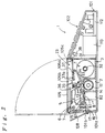
- Figure 2 is a cross-sectional view of Figure 1 taken along line II-II.
- the ink-jet printer 1 of the first embodiment is of the type called a "label printer" for performing a printing operation onto the surface of a tape whose back surface is covered with a releasable sheet via an adhesive layer.
- the ink-jet printer 1 has a thin casing 101 in the form of a generally rectangular prism.
- the front part of the upper plate of the casing 101 forms an operation control panel 102.
- Various keys such as a print button 103 for starting a printing operation and a power switch button 104 are disposed on the operation control panel 102.
- a lid 105 is disposed on the top of the rear part of the casing 101. The lid 105 can be opened and closed by means of rotation about the rear end. By pressing a lid open-close button 106 disposed on the operation control panel 102, a lock is released and the lid 105 may be opened so that the inside of the casing 101 can be seen from the top side of the ink-jet printer 1.
- Beneath the lid 105 is a mounting part 23 in which a tape cartridge 3, described below, can be mounted.
- the tape cartridge 3 can be mounted into or removed from the mounting part 23 when the lid 105 is open.
- the lid 105 has a transparent window 105a through which a user can see whether a tape cartridge 3 is mounted.
- a liquid crystal display unit 107 for displaying character information input via the keys on the operation control panel 102 is disposed in an area adjacent to the lid 105.
- a tape outlet 101b is formed in a rear side 101a of the casing 101 so that a printed tape may be carried out through the tape outlet 101b.
- the tape is guided by a guide plate 108.
- a power supply 112 and a battery 113 such as a nickel-cadmium battery are disposed inside of the casing 101 below the operation control panel 102.
- Figure 3 is a schematic diagram illustrating the main elements of the ink-jet printer 1 disposed inside the casing 101.
- reference numeral 2 denotes a base on which the elements are mounted, wherein the base 2 is placed on the bottom of the casing 101.
- the tape cartridge 3, three ink tanks 4 (4C, 4M, 4Y), and an ink-jet print head 5 are disposed on the base 2.
- the print head 5 is held on a head carriage 6.
- the head carriage 6 is supported by a lead screw 7 extending between right side-plate 22 and left side-plate 21 of the base 2.
- the carriage 6 is also supported by a guide axis (not shown) disposed in parallel to the lead screw 7 so that the carriage 6 can move left and right (along the lead screw) without rotation. That is, if the lead screw 7 is rotated, the head carriage 6 and the print head 5 held by the head carriage 6 move to the right or to the left in the directions (the first directions) denoted by arrows A and B in Figure 3.
- a tape guide element 8 is disposed at the center of the movement range of the print head 5 in such a manner that the tape guide element 8 faces the print head 5.
- the tape guide element 8 is an element corresponding to a platen disposed facing a print head of a printer such as a thermal printer, and the tape guide element 8 defines a printing position of the print head 5.
- the tape guide element 8 forms an excess ink capturing means.
- the top surface of the guide element 8 of the first embodiment comprises an ink filter 81 capable of capturing ink wherein the captured ink can pass through the filter.
- the ink filter 81 may be made of, for example, stainless steel in the form of a mesh.
- the ink filter 81 is attached to the surface of an ink absorber 82 in the form of a rectangular prism of an ink absorbing material.
- the ink captured on the surface of the guide element 8 passes through the ink filter 81 and is then absorbed by the ink absorber 82.
- a head capping mechanism 9 is disposed between the guide element 8 and the right side-plate 22.
- the head capping mechanism 9 is located at a position beyond at one end of the path along which the print head 5 moves during a printing operation.
- the print head 5 moves to the head capping mechanism 9 and is held there in a state in which the print head 5 is capped by a cap face 91 of the capping mechanism 9.
- an ink pump 11 which may be operated manually before starting a printing operation so as to forcibly supply ink from the ink tanks 4 to the print head 5.
- Figure 4 illustrates the layout, as seen from above, of the main elements of the ink-jet printer 1 according to the first embodiment. Referring to Figure 4 as well as other figures, the main elements of the ink-jet printer 1 of the present embodiment will be described below in detail.
- the tape cartridge 3 includes a case 31, a core axis 32 accommodated in the case 31 in such a manner that the core axis 32 can rotate, and a tape T having a width W1 wherein the tape T is wound around the core 32.
- the upper part of one face of the case 31 protrudes toward the rear face of the ink-jet printer 1.
- a tape feeder including a tape guide 33 made of PET (polyethylene) film and a tape pressing roller 34 which is pressed against the surface of the tape guide 33 by a constant elastic force provided by a coil spring 36.
- a supporting element 35 for supporting the tape pressing roller 34 is disposed on a side wall of the case 31 via the coil spring 36 in such a manner that the supporting element 35 can move up and down relative to the tape guide 33.
- the supporting element 35 is coupled to a lever 37.
- the lever 37 has an upper end face 37a protruding outside the case 31 of tape cartridge 3 on the upper side of the case 31. When the upper end face 37a is pushed downward, the tape pressing roller 34 is pressed toward the tape guide 33.
- On the upper surface of the case 31 are six indicators 38 for indicating the width of the tape T inside the case.
- the tape cartridge 3 is removably mounted in the mounting part 23.
- a tape feeding roller 12 is disposed just below the tape guide 33.
- the roller 12 has alternating portions of large diameter and small diameter.
- the lid 105 is disposed just above the tape cartridge 3 so that the tape cartridge can be mounted or removed when the lid 105 is open.
- the source of the recording medium essentially comprises the tape cartridge 3 in which the tape T is accommodated.
- the lid 105 has a pushing element 105b by which the upper end face 37a of the lever 37 is pushed down when the lid 105 is closed.
- the lid 105 which faces the tape width indicators 38 formed on the upper surface of the case 31 of the tape cartridge 3, is provided with detectors 105c for detecting the tape width W1 indicated by the indicators 38.
- the medium path of the tape T fed from the tape cartridge 3 will now be described.
- the tape T is fed out of the case 31 by means of the tape feeding roller 12.
- a plurality of tape guide strips 13 made of a PET film are disposed in such a manner that they are in contact with the surface of the short diameter portions of the tape feeding roller 12. These tape guide strips 13 ensure that the leading edge of the tape T is correctly guided in the forward direction of the medium path.
- a tape guide 14 made of stainless steel is disposed in the tape medium path ahead of the tape guide strips 13.
- the tape T is guided toward the printing position by the guide 14 and a guide disposed opposite the guide 14.
- the printing position is defined by the positions of the print head 5 and the guide element 8 disposed opposite the print head 5.
- the top surface of the guide element 8 is formed of the ink filter 81 attached to the surface of the ink absorber 82 composed of ink absorbing material. After passing the printing position, the tape T is pressed against a tape guide 16 by a tape pressing roller 15, and further passes a tape cutting position 17. Then, the tape T is carried out through the tape outlet 101b.
- a tape carrying motor 18 is disposed on the inner surface of the side-plate 22 of the base 2.
- the output shaft 18a of the motor is connected via a train of gears 181 to the end of the rotating axis 121 of the tape feeding roller 12.
- the train of gears 181 has the capability of switching the power. That is, if the head carriage 6 moves toward the side-plate 22 thereby pressing a protrusion 182 protruding inward from the side-plate 22, then the power transmission path is switched so that the power of the motor 18 is transmitted to the capping mechanism 9.
- the means for carrying the tape serving as the recording medium essentially comprises the tape feeding roller 12, the motor 18 serving as the power source for the tape feeding roller 12, and the train of gears 181 serving as the power transmission from the motor 18 to the roller 12.
- a head driving motor 19 is disposed on the inner surface of the left side-plate 21.
- the output shaft 19a of this motor is connected to the end of the lead screw 7 via a reduction mechanism 191 including a train of gears.
- the ink supplying means essentially comprises the ink tanks 4, three ink tubes 41 (41Y, 41M, 41C) through which inks are supplied from the ink tanks 4 to the print head 5, and the ink pump 11 by which the inks may be pumped manually.
- the three ink tanks 4C, 4M, and 4Y contain cyan, magenta, and yellow inks, respectively, with which a color printing operation is accomplished.
- the maximum allowable width of the tape T is W(max) as shown in Figure 4.
- the print head 5 is capable of performing a printing operation across the width of the tape (in the directions of the movement of the print head 5) over the maximum printing range W(p) which extends beyond the maximum allowable tape width W(max) on both right and left sides of the tape.
- the ink filter 81 forming the top surface of the guide element 8 is disposed over the maximum printing range.
- the tape has a width of W1, and the printing range of the print head 5 is set to W(p1) which includes the tape width W1.
- the width of the tape in the tape cartridge 3 is detected by reading the six indicators 38 disposed on the upper surface of the case 31.
- the indication of the tape width is possible for example by opening corresponding indicators 38.
- the tape width is determined by detecting which, if any, of the indicators 38 are open using mechanical or optical sensors forming the detectors 105c.
- FIG. 6 is a block diagram illustrating a control system of the ink-jet printer 1 according to the first embodiment.
- reference numeral 100 denotes a control circuit constructed with a microcomputer.
- An input unit 110 including the keys disposed on the operation control panel 102 of the ink-jet printer 1 is connected to respective inputs of the control circuit 100.
- the detector 105c for detecting the tape width is connected to respective inputs of the control circuit 100.
- Outputs of the control circuit 100 are connected to the display unit 107 such as a liquid crystal display device for displaying various information, a printer controller 140 for control the printing operation performed by the print head 5, and motor drivers 150 and 160 for control and driving the motors 18 and 19.
- the printing range is set to a value corresponding to the width of the tape in the tape cartridge 3, and a printing operation such as a solid printing operation is performed as will be described later.
- the control circuit 100 serves as the central part of the control system for the printing and driving means.
- the printing range is set to W(p1) which is greater than the width W1 of the tape.
- the motor 18 is driven so that the tape feeding roller 12 is rotated, thereby feeding the tape T from the tape cartridge 3 toward the printing position.
- the motor 19 rotates the lead screw 7 thereby moving the print head 5 via the carriage 6.
- the printing operation is performed over a range greater than the width W1 of the tape, thereby allowing the printing operation to occur across the entire width of the tape T.
- ink droplets ejected from the print head 5 before the print head 5 reaches the edge T1 of the tape T and after the print head 5 has passed the edge T2 of the tape T, travel toward the guide element 8 without striking the tape T.
- the guide element 8 since the ink filter 81 of the guide element 8 is disposed over the entire printing range, the ejected ink droplets are captured by the ink filter 81 and do not reach the other parts.
- the guide element 8 also comprises the ink absorber 82 which absorbs the ink droplets that have reached the surface and passed through the ink filter 81. In this way, the ink droplets are trapped via the surface of the guide element 8 and the following part of the tape T is not dirtied with ink droplets.
- the head carriage 6 moves in the direction denoted by the arrow B until it returns to a position near the left side-plate 21 as shown in Figure 4. Then a rotary cutter 61 on the carriage 6 is driven as the carriage 6 is moved again in the direction denoted by the arrow A with the cutter 61 remaining in the projected position.
- the tape T may be cut at a point along the length of the tape T after, on or before the position of the printing.
- the roller 12 may be rotated by the motor 18 in the opposite direction so that the new leading edge of the tape T at the cut returns to a position immediately prior to the printing position. Furthermore, the carriage 6 moves to the right side-plate 22 so that the protrusion 182 is pressed outward by the side face of the carriage 6 thereby cutting the linkage between the motor 18 and the tape feeding roller 12. As a result, the roller 12 stops its rotation and the capping mechanism 9 is then driven so that the print head 5 is capped.
- the tape T (with its leading edge located at the position immediately prior to the printing position) is wound backward into the tape case 31 until the leading edge of the tape returns to the position between the pressing roller 34 and the tape guide 33 forming the tape feeding mechanism.
- the printing range is set accordingly. For example, if the specified region is bounded by the left edge of the tape T, the printing range is set so that the printing operation starts at a position prior to the left edge of the tape T. If the specified region is bounded by the right edge of the tape T, the printing range is set so that the printing operation stops after the print head has passed the right edge of the tape T.
- an ink-jet printer is able to perform a solid printing operation across the entire width of a tape and/or along the entire length of a tape.
- the printing operation is started slightly before the leading edge of the tape reaches the printing position of the print head 5.
- the printing operation is continued until after the location that will become the trailing edge of the tape has passed the printing position.
- the tape is cut by rotary cutter 61 at the desired location for the trailing edge.
- Figures 7, 8, and 9 illustrate the main elements of a second embodiment of an ink-jet printer for performing a solid printing operation on a large recording medium such as a poster, although the second embodiment may also be applied in an ink-jet printer for printing a relatively small recording medium such as a tape as in the first embodiment.
- the ink-jet printer 200 according to the second embodiment is very similar to that of the first embodiment except that the recording medium is in the form of a cut sheet such as a poster, the carriage mechanism of the print head is driven by a belt and pulley rather than gears and a lead screw, and the excess ink capturing means is constructed on the paper guide in a different manner.
- the recording medium is in the form of a cut sheet such as a poster
- the carriage mechanism of the print head is driven by a belt and pulley rather than gears and a lead screw
- the excess ink capturing means is constructed on the paper guide in a different manner.
- a carriage 202 holds and carries not only a print head at its lower part but also ink cartridges 203Y, 203M, and 203C containing three color inks.
- One side of the carriage 202 is supported by a carriage guide plate 204.
- the other side of the carriage 202 is supported by carriage guide shaft 206 extending parallel to the guide plate 204.
- the carriage 202 is able to move in both directions across the width of recording medium 205, along the surface of the carriage guide plate 204.
- the carriage 202 is connected to a timing belt 209 which travels between a driving pulley 207 and a driven pulley 208.
- the driving pulley 207 is connected to the output shaft of a carriage motor 210 so that the print head held by the carriage 202 can be moved by the motor 210 in both directions across the width of the recording medium 205.
- a feeding roller 221 and a pair of pressing rollers 222 and 223 which are pressed against the surface of the feeding roller 221.
- the recording medium 205 is carried through these elements toward the printing position of the print head.
- a guiding element for guiding the recording medium 205 is disposed below the print head over a range including at least the reciprocating movement range of the print head.
- the guiding element is provided with an excess ink capturing mechanism 211.
- the excess ink capturing mechanism 211 includes: a captured ink reservoir 212 in the form of a rectangular box having a width sufficiently greater than the width of the recording medium used; an ink absorbing material 213 disposed inside the captured ink reservoir 212; and a plurality of guide ribs 214 for guiding the recording medium.
- the captured ink reservoir 212 comprises a bottom plate 212a and front, rear, left, and right side walls 212e, 212b, 212c and 212d, respectively, rising from the periphery of the bottom plate 212a, wherein the upper side of the reservoir 212 is open.
- the ink absorbing material 213 is disposed on the bottom plate 212a of the captured ink reservoir 212 in such a manner that the ink absorbing material 213 extends along the left side wall 212c, the rear side wall 212b, and the right side wall 212d.
- the vertically-protruding guide ribs 214 in the form of a sector are attached to the bottom plate 212a, are displaced at equal intervals across the width of the bottom plate 212a and surrounded by the ink absorbing material 213 and the front side wall 212e of the captured ink reservoir 212.
- the upper ends of these ribs 214 extend slightly above the side walls of the captured ink reservoir 212 so that the recording medium 205 can be guided by the upper end portions of these ribs 214 when the recording medium 205 passes over the captured ink reservoir 212.
- An ink exhaust means is provided at the bottom plate 212a of the captured ink reservoir 212.
- pipes 215 are connected to the captured ink reservoir 212 in such a manner that these pipes may carry away ink that is absorbed by the ink absorbing material 213.
- the other ends of the pipes 215 are connected to a suction pump (not shown) which facilitates the removal of ink from the ink absorbing material 213.
- the ink absorbing material 213 includes the printing range W(p) which is set to a value greater than the maximum medium width W(max) and which extends beyond the left and right sides, 205L and 205R, respectively, of the recording medium 205 as shown in Figure 9.
- W(p) the printing range W(p) which is set to a value greater than the maximum medium width W(max) and which extends beyond the left and right sides, 205L and 205R, respectively, of the recording medium 205 as shown in Figure 9.
- the printing operation is started when the print head has come to a position slightly prior to the left edge 205L of the recording medium 205, and it is continued until the print head has passed the right edge 205R of the recording medium 205, as is done in the first embodiment.
- the ink droplets which do not arrive at the surface of the recording medium 205 will reach the surface of the ink absorbing material 213 in the excess ink capturing mechanism 211 and will be absorbed by the ink absorbing material 213. This ensures that subsequent recording media are not dirtied with ink.
- the printing position of the print head is denoted by line P.
- the printing position is set at the center of the width of the ink absorbing material in the medium movement direction (that is, at the center between lines L1 and L2).
- This technique ensures that the solid printing operation is performed without producing a non-printed area at the leading and trailing edges (upstream and downstream edges) of the recording medium 205. Furthermore, during such a solid printing operation, the ink droplets which travel without reaching the recording medium are captured by the ink absorbing material disposed at the back side of the recording medium and absorbed into it. Therefore, this technique avoids the problem that the ink droplets are deposited on undesired portions and the following recording medium is made dirty with the deposited ink.
- the ink absorbing material 213 is distributed along the three side walls 212b, 212c and 212d. In an alternative embodiment, the ink absorbing material 213 is distributed across the entire bottom plate 212a so that the ink absorbing material 213 has a rectangular shape. In yet another embodiment, the ink absorbing material 213 has a rectangular shape with a hole at its center. However, it is more economical and desirable to dispose the ink absorbing material 213 in only the areas which ink droplets can reach.
- the width of the recording medium 205 is detected by an optical sensor 231 attached to a side of the carriage 202.
- the optical sensor 231 receives light reflected from the surface of the recording medium 205 and is able to detect the edges of the recording medium 205 from changes in the amount of light received when it moves past the edges, thereby detecting the width of the recording medium used.
- the printing range is set to extend beyond the medium on both sides.
- An optical sensor 231 may be attached to each side of the carriage 202 or, alternatively, only one optical sensor 231 may be employed. If only one optical sensor 231 is used, the carriage is moved across the entire width of the recording medium 205 before starting a printing operation so that both edges can be detected.
- Figure 10 illustrates a third embodiment of an ink-jet printer with an ink capturing mechanism based on a modification of the second embodiment.
- this modified ink capturing mechanism 311 comprises a captured ink reservoir 312 and an ink absorbing material 313 disposed in the captured ink reservoir 312.
- the excess ink capturing mechanism 311 in the third embodiment is adapted to move with the print head carriage 315.
- the excess ink capturing mechanism 311 of the third embodiment is supported by a carriage 314 which is in turn supported by a pair of guide shafts 316 and 317 that are parallel to each other, allowing the carriage 314 to move in both directions along the guide shafts.
- the carriage 314 is connected to a timing belt 318 which travels between a driving pulley 319 and a driven pulley 320.
- the driving pulley 319 is connected to the output shaft of a carriage motor 322 via a train of reduction gears 321.
- the head carriage 315 for holding and carrying the print head is supported so that it can move in both directions along a guide plate 332 and a guide shaft 333, as in the second embodiment.
- the head carriage 315 is connected to a timing belt 336 which travels between a driving pulley 334 and a driven pulley 335.
- the driving pulley 334 is connected to the output shaft of the carriage motor 322 via a train of gears 337.
- the two timing belts 318 and 336 are driven in synchronization with each other so that both the excess ink capturing mechanism 311 and the print head may move together in both directions.
- a guide element 361 having a width greater than the maximum possible printing range is disposed between the head carriage 315 and the excess ink capturing mechanism 311 in such a manner that an end portion of the guide element 361 extends upstream in the medium path of medium 362 movement by a predetermined amount.
- the excess ink capturing mechanism 311 moves together with the print head, there is no need to distribute the ink absorbing material over a range including the entire stroke of the print head unlike that required in the second embodiment. This allows a reduction in the size of the excess ink capturing mechanism.
- the excess ink capturing mechanism 311 that moves together with the print head is generally preferable to the excess ink capturing mechanism 211 which is formed across the entire width of the recording medium as in the second embodiment.
- the ink absorbing material 313 be connected to an ink tank 343 via a pipe 341 so that the accumulated ink may be removed from the ink capturing mechanism 311 into the ink tank 343 by means of a suction pump 342.
- the present invention is not limited to application in a color printer.
- the present invention may also be applied in an ink-jet printer having only one ink tank for ink of any color such as black.
- a white ink in addition to the three colors cyan, magenta, and yellow.
- This allows high-quality reproduction for each color even when printing is performed onto a recording medium having a color other than white.
- Colors which can be created by mixing three ink colors (cyan, magenta, and yellow) are limited to red, green, blue, and black.
- Other colors are obtained by means of area gradation based on a dither method. As a result, these other colors are poor in quality compared to the colors that can be produced by means of normal printing.
- it is impossible to create white by mixing cyan, magenta, and yellow.
- a white color ink is employed in addition to the above three colors, the problems described above can be avoided.
- four color inks cyan, magenta, yellow and white
- the color of the recording medium can be easily changed by mounting a tape cartridge 3 having the tape T of the desired color.
Landscapes
- Ink Jet (AREA)
- Printers Characterized By Their Purpose (AREA)
- Handling Of Continuous Sheets Of Paper (AREA)
- Accessory Devices And Overall Control Thereof (AREA)
- Character Spaces And Line Spaces In Printers (AREA)
Applications Claiming Priority (6)
| Application Number | Priority Date | Filing Date | Title |
|---|---|---|---|
| JP256868/94 | 1994-10-21 | ||
| JP25686894 | 1994-10-21 | ||
| JP25686894 | 1994-10-21 | ||
| JP229543/95 | 1995-09-06 | ||
| JP22954395 | 1995-09-06 | ||
| JP7229543A JPH08169155A (ja) | 1994-10-21 | 1995-09-06 | インクジェットプリンタ及びそれに用いる記録媒体、記録媒体供給源 |
Publications (3)
| Publication Number | Publication Date |
|---|---|
| EP0707973A2 true EP0707973A2 (de) | 1996-04-24 |
| EP0707973A3 EP0707973A3 (de) | 1997-07-23 |
| EP0707973B1 EP0707973B1 (de) | 2000-04-26 |
Family
ID=26528864
Family Applications (1)
| Application Number | Title | Priority Date | Filing Date |
|---|---|---|---|
| EP95116583A Expired - Lifetime EP0707973B1 (de) | 1994-10-21 | 1995-10-20 | Tintenstrahldrucker und dessen Gebrauch mit einem Aufzeichnungsträger |
Country Status (8)
| Country | Link |
|---|---|
| US (1) | US5997129A (de) |
| EP (1) | EP0707973B1 (de) |
| JP (1) | JPH08169155A (de) |
| KR (1) | KR100403880B1 (de) |
| CN (1) | CN1106286C (de) |
| DE (1) | DE69516478T2 (de) |
| HK (1) | HK1014168A1 (de) |
| TW (1) | TW303450B (de) |
Cited By (12)
| Publication number | Priority date | Publication date | Assignee | Title |
|---|---|---|---|---|
| EP0992347A2 (de) * | 1998-10-09 | 2000-04-12 | Eastman Kodak Company | Drucker zum bedrucken eines Empfängers in voller Breite unter Ausschluss der Kanten des Empfängers und Verfahren zur Montage des Druckers |
| EP0995603A2 (de) * | 1998-10-20 | 2000-04-26 | Hewlett-Packard Company | Apparat und Verfahren zum Drucken eines randloses Bildes |
| EP1084852A1 (de) * | 1999-09-14 | 2001-03-21 | Brother Kogyo Kabushiki Kaisha | Kassette und Gerät zum Festellen ob diese angebracht ist |
| EP1059168A3 (de) * | 1999-06-08 | 2001-04-04 | Canon Kabushiki Kaisha | Tintenstrahlaufzeichnungsgerät und -verfahren |
| EP1093926A2 (de) | 1994-12-28 | 2001-04-25 | Seiko Epson Corporation | Verfahren für Farbstrahldrucker auf einem bandförmigen Aufzeichnungsmedium und Aufzeichnungsträger |
| WO2002011990A1 (de) * | 2000-08-03 | 2002-02-14 | Agfa-Gevaert Aktiengesellschaft | Vorrichtung zum randlosbedrucken von bildmaterial mittels eines ink-jet-printers |
| EP1186993A2 (de) * | 2000-09-11 | 2002-03-13 | Seiko Epson Corporation | Hauptrechnergestützte Vorrichtung und Verfahren zum randlosen Ausdrucken |
| EP1147901A3 (de) * | 2000-04-18 | 2002-04-10 | Seiko Epson Corporation | Tintenstrahlaufzeichnungsvorrichtung |
| EP1285770A2 (de) * | 2001-08-10 | 2003-02-26 | Canon Kabushiki Kaisha | Tintenstrahldruckvorrichtung |
| EP1364799A2 (de) * | 2002-05-21 | 2003-11-26 | Brother Kogyo Kabushiki Kaisha | Farbstrahlaufzeichnungsgerät |
| EP1371490A1 (de) * | 2002-06-11 | 2003-12-17 | Brother Kogyo Kabushiki Kaisha | Tintenstrahlaufzeichnungsgerät |
| US7401916B2 (en) * | 1999-04-06 | 2008-07-22 | Seiko Epson Corporation | Ink-jet recording apparatus and recording method therefor |
Families Citing this family (59)
| Publication number | Priority date | Publication date | Assignee | Title |
|---|---|---|---|---|
| US6549298B1 (en) * | 2000-01-12 | 2003-04-15 | Jonathan D. Sieber | Method and apparatus for bleed-printing and method and apparatus for decorating a paper object |
| TW357123B (en) * | 1997-07-30 | 1999-05-01 | Seiko Epson Corp | Tape cartridge and tape printing device |
| DE19832093A1 (de) * | 1997-08-22 | 1999-02-25 | Esselte Nv | Banddruckgerät |
| JP3731364B2 (ja) | 1999-01-21 | 2006-01-05 | セイコーエプソン株式会社 | テープ印刷装置およびその制御方法 |
| JP4650645B2 (ja) * | 1999-04-06 | 2011-03-16 | セイコーエプソン株式会社 | インクジェット記録装置 |
| JP2005111995A (ja) * | 1999-12-01 | 2005-04-28 | Seiko Epson Corp | インクジェット式記録装置 |
| JP4697457B2 (ja) * | 1999-12-01 | 2011-06-08 | セイコーエプソン株式会社 | インクジェット式記録装置のプラテン |
| JP2010089519A (ja) * | 1999-12-01 | 2010-04-22 | Seiko Epson Corp | インクジェット式記録装置 |
| JP2002019094A (ja) * | 2000-07-07 | 2002-01-22 | Canon Aptex Inc | インクジェット記録装置および記録方法 |
| EP1299242B1 (de) * | 2000-07-11 | 2011-10-12 | Textilma Ag | Anlage zur kontinuierlichen herstellung eines bedruckten textilbandes, insbesondere eines etikettenbandes |
| TWI290946B (en) * | 2000-07-26 | 2007-12-11 | Nippon Kayaku Kk | Cyan dye mixture, aqueous cyanic ink composition and ink-jet printing method |
| US6930696B2 (en) | 2000-09-27 | 2005-08-16 | Seiko Epson Corporation | Printing up to edges of printing paper without platen soiling |
| JP4622073B2 (ja) * | 2000-09-27 | 2011-02-02 | セイコーエプソン株式会社 | プラテンを汚すことなく印刷媒体の端部まで行う印刷 |
| US6746101B2 (en) * | 2000-09-27 | 2004-06-08 | Seiko Epson Corporation | Printing up to edges of printing paper without platen soiling |
| DE60131344T2 (de) * | 2000-09-27 | 2008-09-11 | Seiko Epson Corp. | Drucken mit sensorgestützter Positionierung von Druckpapier |
| JP3762228B2 (ja) * | 2001-01-31 | 2006-04-05 | キヤノン株式会社 | 記録装置および記録方法 |
| US6409305B1 (en) * | 2001-02-09 | 2002-06-25 | Hewlett-Packard Company | Full bleed printmode to minimize overspray |
| CN1215940C (zh) * | 2001-06-04 | 2005-08-24 | 精工爱普生株式会社 | 带翻页机构的打印机 |
| JP2003191502A (ja) | 2001-12-28 | 2003-07-09 | Seiko Epson Corp | インクジェット式記録装置およびインクジェット式記録装置のフラッシング方法 |
| US6840617B2 (en) * | 2002-04-02 | 2005-01-11 | Lexmark International, Inc. | Mid-frame for an imaging apparatus |
| CN100453334C (zh) * | 2002-08-08 | 2009-01-21 | 精工爱普生株式会社 | 记录设备、记录方法和计算机系统 |
| KR20040016521A (ko) * | 2002-08-17 | 2004-02-25 | 삼성전자주식회사 | 잉크젯 프린터 |
| JP3835383B2 (ja) | 2002-09-09 | 2006-10-18 | セイコーエプソン株式会社 | 液体吐出装置及びコンピュータシステム |
| JP4389432B2 (ja) | 2002-09-09 | 2009-12-24 | セイコーエプソン株式会社 | 液体吐出装置、コンピュータシステム、及び、液体吐出方法 |
| KR100449741B1 (ko) * | 2002-10-01 | 2004-09-22 | 삼성전자주식회사 | 단부 인쇄를 위한 구조를 가지는 인쇄기 |
| US20040125164A1 (en) * | 2002-10-01 | 2004-07-01 | Park Jin-Ho | Printer with structure providing edge printing and a shingling method thereof |
| JP3975956B2 (ja) * | 2003-03-31 | 2007-09-12 | ブラザー工業株式会社 | 画像形成装置 |
| JP4013909B2 (ja) * | 2003-04-10 | 2007-11-28 | セイコーエプソン株式会社 | 液体噴射装置 |
| DE602004019507D1 (de) | 2003-04-15 | 2009-04-02 | Seiko Epson Corp | Vorrichtung, system und verfahren zum abführen von flüssigkeit |
| JP4487495B2 (ja) * | 2003-04-24 | 2010-06-23 | コニカミノルタホールディングス株式会社 | インクジェットプリンタ |
| JP2004338383A (ja) * | 2003-04-25 | 2004-12-02 | Canon Inc | インクカートリッジ、該インクカートリッジを搭載する記録装置および該インクタンクの製造方法 |
| US7063416B2 (en) * | 2003-06-11 | 2006-06-20 | Dimatix, Inc | Ink-jet printing |
| US7445312B2 (en) | 2003-06-26 | 2008-11-04 | Seiko Epson Corporation | Inkjet printer and inkjet print method |
| US7108344B2 (en) * | 2003-11-03 | 2006-09-19 | Hewlett-Packard Devleopment Company, L.P. | Printmode for narrow margin printing |
| US7011383B2 (en) * | 2004-01-08 | 2006-03-14 | Lexmark International, Inc. | Method for borderless printing using a printer adapted to print dots |
| US7645037B2 (en) | 2004-03-11 | 2010-01-12 | Hewlett-Packard Development Company, L.P. | Printer structure |
| US7699460B2 (en) | 2004-08-12 | 2010-04-20 | Canon Kabushiki Kaisha | Printing apparatus and printing method |
| US7140708B2 (en) * | 2004-08-30 | 2006-11-28 | Lexmark International, Inc. | Method of edge-to-edge imaging with an imaging apparatus |
| US20060066700A1 (en) * | 2004-09-30 | 2006-03-30 | Simpson Charles J | Edge-to-edge printing |
| EP1693217B1 (de) * | 2005-02-16 | 2009-01-14 | Seiko Epson Corporation | Flüssigkeitsausstossgerät und Druckwiderlagereinheit |
| JP4483727B2 (ja) * | 2005-07-15 | 2010-06-16 | セイコーエプソン株式会社 | 印刷画像作成装置、印刷画像作成方法およびプログラム |
| KR100667832B1 (ko) * | 2005-11-12 | 2007-01-11 | 삼성전자주식회사 | 주행 모듈을 포함하는 화상독취장치 |
| JP4207955B2 (ja) * | 2005-12-27 | 2009-01-14 | ブラザー工業株式会社 | インクジェット記録装置 |
| US7717634B1 (en) | 2006-01-11 | 2010-05-18 | Lexmark International, Inc. | Trough support ribs |
| US7524050B2 (en) * | 2006-04-11 | 2009-04-28 | Fujifilm Dimatix, Inc. | Ink jet printing |
| JP4626563B2 (ja) * | 2006-04-24 | 2011-02-09 | セイコーエプソン株式会社 | インクジェット式記録装置 |
| JP4600538B2 (ja) * | 2008-07-28 | 2010-12-15 | セイコーエプソン株式会社 | ドット記録方法、ドット記録制御装置、ドット記録装置およびコンピュータ読み取り可能な記録媒体 |
| JP2009083514A (ja) * | 2009-01-28 | 2009-04-23 | Seiko Epson Corp | プラテンを汚すことなく印刷用紙の端部まで行う印刷 |
| JP4656255B2 (ja) * | 2010-07-12 | 2011-03-23 | セイコーエプソン株式会社 | プラテンを汚すことなく印刷媒体の端部まで行う印刷 |
| US8395784B2 (en) * | 2010-09-27 | 2013-03-12 | Eastman Kodak Company | Method of lead edge detection in an inkjet printer |
| JP2011140238A (ja) * | 2011-04-18 | 2011-07-21 | Seiko Epson Corp | 液体噴射装置 |
| JP5794000B2 (ja) * | 2011-06-30 | 2015-10-14 | ブラザー工業株式会社 | 液体吐出装置 |
| CN103845959B (zh) * | 2012-11-30 | 2015-10-28 | 北汽福田汽车股份有限公司 | 纸带滤纸清洁设备及方法 |
| CN107097539B (zh) * | 2013-11-12 | 2019-12-31 | 精工爱普生株式会社 | 打印机 |
| CN104441983B (zh) * | 2014-11-25 | 2016-08-24 | 柳州钢铁股份有限公司 | 钢板在线自动喷标机的束流装置 |
| JP2017001275A (ja) * | 2015-06-10 | 2017-01-05 | 株式会社日立産機システム | インクジェット記録装置 |
| JP6756306B2 (ja) * | 2017-06-15 | 2020-09-16 | カシオ計算機株式会社 | ラベルプリンタ、印刷方法及びラベルプリンタに用いられるプログラム |
| US11027561B2 (en) | 2019-02-01 | 2021-06-08 | Assa Abloy Ab | Ink jet card printer having a dual belt card transport |
| CN109941002A (zh) * | 2019-04-02 | 2019-06-28 | 广东工业大学 | 一种微型打印机 |
Citations (5)
| Publication number | Priority date | Publication date | Assignee | Title |
|---|---|---|---|---|
| EP0345018A1 (de) * | 1988-05-30 | 1989-12-06 | Fujitsu Limited | Bilderzeugungsvorrichtung und Bilderzeugungsverfahren |
| EP0451460A2 (de) * | 1990-02-13 | 1991-10-16 | Canon Kabushiki Kaisha | Aufzeichnungsvorrichtung |
| EP0526154A2 (de) * | 1991-07-29 | 1993-02-03 | Canon Kabushiki Kaisha | Aufzeichnungsgerät versehen mit einer Aufzeichnungsträgerlage-Ermittlungsvorrichtung |
| US5291227A (en) * | 1991-05-17 | 1994-03-01 | Ricoh Company, Ltd. | Ink jet printer having improved paper transport mechanism |
| EP0616893A2 (de) * | 1993-03-26 | 1994-09-28 | Canon Kabushiki Kaisha | Farbstrahldruckverfahren und -vorrichtung |
Family Cites Families (4)
| Publication number | Priority date | Publication date | Assignee | Title |
|---|---|---|---|---|
| JPS5615364A (en) * | 1979-07-18 | 1981-02-14 | Toshiba Corp | Ink jet recorder |
| JPH04286655A (ja) * | 1991-03-15 | 1992-10-12 | Canon Inc | インクジェット記録装置 |
| JPH06166175A (ja) * | 1992-11-27 | 1994-06-14 | Seiko Epson Corp | インクジェット記録装置 |
| JPH0768814A (ja) * | 1993-09-06 | 1995-03-14 | Brother Ind Ltd | テープ印字装置 |
-
1995
- 1995-09-06 JP JP7229543A patent/JPH08169155A/ja not_active Withdrawn
- 1995-09-27 TW TW084110211A patent/TW303450B/zh not_active IP Right Cessation
- 1995-10-19 KR KR1019950036100A patent/KR100403880B1/ko not_active IP Right Cessation
- 1995-10-20 US US08/545,943 patent/US5997129A/en not_active Expired - Lifetime
- 1995-10-20 DE DE69516478T patent/DE69516478T2/de not_active Expired - Lifetime
- 1995-10-20 CN CN95120291A patent/CN1106286C/zh not_active Expired - Lifetime
- 1995-10-20 EP EP95116583A patent/EP0707973B1/de not_active Expired - Lifetime
-
1998
- 1998-12-24 HK HK98115516A patent/HK1014168A1/xx not_active IP Right Cessation
Patent Citations (5)
| Publication number | Priority date | Publication date | Assignee | Title |
|---|---|---|---|---|
| EP0345018A1 (de) * | 1988-05-30 | 1989-12-06 | Fujitsu Limited | Bilderzeugungsvorrichtung und Bilderzeugungsverfahren |
| EP0451460A2 (de) * | 1990-02-13 | 1991-10-16 | Canon Kabushiki Kaisha | Aufzeichnungsvorrichtung |
| US5291227A (en) * | 1991-05-17 | 1994-03-01 | Ricoh Company, Ltd. | Ink jet printer having improved paper transport mechanism |
| EP0526154A2 (de) * | 1991-07-29 | 1993-02-03 | Canon Kabushiki Kaisha | Aufzeichnungsgerät versehen mit einer Aufzeichnungsträgerlage-Ermittlungsvorrichtung |
| EP0616893A2 (de) * | 1993-03-26 | 1994-09-28 | Canon Kabushiki Kaisha | Farbstrahldruckverfahren und -vorrichtung |
Cited By (30)
| Publication number | Priority date | Publication date | Assignee | Title |
|---|---|---|---|---|
| EP1093926A2 (de) | 1994-12-28 | 2001-04-25 | Seiko Epson Corporation | Verfahren für Farbstrahldrucker auf einem bandförmigen Aufzeichnungsmedium und Aufzeichnungsträger |
| EP0992347A3 (de) * | 1998-10-09 | 2001-01-10 | Eastman Kodak Company | Drucker zum bedrucken eines Empfängers in voller Breite unter Ausschluss der Kanten des Empfängers und Verfahren zur Montage des Druckers |
| EP0992347A2 (de) * | 1998-10-09 | 2000-04-12 | Eastman Kodak Company | Drucker zum bedrucken eines Empfängers in voller Breite unter Ausschluss der Kanten des Empfängers und Verfahren zur Montage des Druckers |
| EP0995603A2 (de) * | 1998-10-20 | 2000-04-26 | Hewlett-Packard Company | Apparat und Verfahren zum Drucken eines randloses Bildes |
| EP0995603A3 (de) * | 1998-10-20 | 2000-09-13 | Hewlett-Packard Company | Apparat und Verfahren zum Drucken eines randloses Bildes |
| US8277042B2 (en) * | 1999-04-06 | 2012-10-02 | Seiko Epson Corporation | Ink-jet recording apparatus and recording method therefor |
| US7401916B2 (en) * | 1999-04-06 | 2008-07-22 | Seiko Epson Corporation | Ink-jet recording apparatus and recording method therefor |
| US20110141170A1 (en) * | 1999-04-06 | 2011-06-16 | Seiko Epson Corporation | Ink-Jet Recording Apparatus and Recording Method Therefor |
| US20120026266A1 (en) * | 1999-04-06 | 2012-02-02 | Seiko Epson Corporation | Ink-Jet Recording Apparatus and Recording Method Therefor |
| US8267512B2 (en) * | 1999-04-06 | 2012-09-18 | Seiko Epson Corporation | Ink-jet recording apparatus and recording method therefor |
| EP1059168A3 (de) * | 1999-06-08 | 2001-04-04 | Canon Kabushiki Kaisha | Tintenstrahlaufzeichnungsgerät und -verfahren |
| US6457803B1 (en) | 1999-06-08 | 2002-10-01 | Canon Kabushiki Kaisha | Ink jet recording apparatus and ink jet recording method |
| EP1084852A1 (de) * | 1999-09-14 | 2001-03-21 | Brother Kogyo Kabushiki Kaisha | Kassette und Gerät zum Festellen ob diese angebracht ist |
| EP1147901A3 (de) * | 2000-04-18 | 2002-04-10 | Seiko Epson Corporation | Tintenstrahlaufzeichnungsvorrichtung |
| WO2002011990A1 (de) * | 2000-08-03 | 2002-02-14 | Agfa-Gevaert Aktiengesellschaft | Vorrichtung zum randlosbedrucken von bildmaterial mittels eines ink-jet-printers |
| US6733109B1 (en) | 2000-08-03 | 2004-05-11 | Agfa-Gevaert Aktiengesellschaft | Device for borderless printing of images using an ink jet printer |
| EP1186993A3 (de) * | 2000-09-11 | 2003-05-21 | Seiko Epson Corporation | Hauptrechnergestützte Vorrichtung und Verfahren zum randlosen Ausdrucken |
| EP1186993A2 (de) * | 2000-09-11 | 2002-03-13 | Seiko Epson Corporation | Hauptrechnergestützte Vorrichtung und Verfahren zum randlosen Ausdrucken |
| US7224482B2 (en) | 2000-09-11 | 2007-05-29 | Seiko Epson Corporation | Printer host and storage medium storing operation program of the printer host |
| EP1605345A3 (de) * | 2000-09-11 | 2006-08-02 | Seiko Epson Corporation | Drucker-Host zum randlosen Ausdrucken und Speichermedium um das Betriebsprogramm zu speichern |
| EP1605345A2 (de) * | 2000-09-11 | 2005-12-14 | Seiko Epson Corporation | Drucker-Host zum randlosen Ausdrucken und Speichermedium um das Betriebsprogramm zu speichern |
| KR100537703B1 (ko) * | 2001-08-10 | 2005-12-20 | 캐논 가부시끼가이샤 | 잉크젯 인쇄 장치 |
| US7011389B2 (en) | 2001-08-10 | 2006-03-14 | Canon Kabushiki Kaisha | Ink jet printing apparatus |
| EP1285770A3 (de) * | 2001-08-10 | 2003-06-11 | Canon Kabushiki Kaisha | Tintenstrahldruckvorrichtung |
| EP1285770A2 (de) * | 2001-08-10 | 2003-02-26 | Canon Kabushiki Kaisha | Tintenstrahldruckvorrichtung |
| US6869163B2 (en) | 2002-05-21 | 2005-03-22 | Brother Kogyo Kabushiki Kaisha | Ink-jet recording apparatus |
| EP1364799A3 (de) * | 2002-05-21 | 2004-12-01 | Brother Kogyo Kabushiki Kaisha | Farbstrahlaufzeichnungsgerät |
| EP1364799A2 (de) * | 2002-05-21 | 2003-11-26 | Brother Kogyo Kabushiki Kaisha | Farbstrahlaufzeichnungsgerät |
| US6830314B2 (en) | 2002-06-11 | 2004-12-14 | Brother Kogyo Kabushiki Kaisha | Inkjet recording apparatus |
| EP1371490A1 (de) * | 2002-06-11 | 2003-12-17 | Brother Kogyo Kabushiki Kaisha | Tintenstrahlaufzeichnungsgerät |
Also Published As
| Publication number | Publication date |
|---|---|
| DE69516478D1 (de) | 2000-05-31 |
| JPH08169155A (ja) | 1996-07-02 |
| CN1106286C (zh) | 2003-04-23 |
| CN1134360A (zh) | 1996-10-30 |
| TW303450B (de) | 1997-04-21 |
| EP0707973A3 (de) | 1997-07-23 |
| KR960013663A (ko) | 1996-05-22 |
| DE69516478T2 (de) | 2000-10-26 |
| US5997129A (en) | 1999-12-07 |
| HK1014168A1 (en) | 1999-09-24 |
| KR100403880B1 (ko) | 2004-02-25 |
| EP0707973B1 (de) | 2000-04-26 |
Similar Documents
| Publication | Publication Date | Title |
|---|---|---|
| EP0707973B1 (de) | Tintenstrahldrucker und dessen Gebrauch mit einem Aufzeichnungsträger | |
| EP0685958B1 (de) | Bildinformationsverarbeitungssystem | |
| KR100407080B1 (ko) | 잉크제트프린터의카트리지및잉크제트프린터 | |
| EP0719650B1 (de) | Verfahren für Farbstrahldrucker auf einem bandförmigen Aufzeichnungsmedium und Aufzeichnungsträger | |
| JP3183115B2 (ja) | インクジェットプリンタ | |
| US6352333B2 (en) | Method and apparatus for preventing nozzle clogging in ink jet printing apparatus | |
| DE69623065T2 (de) | Tintenstrahlaufzeichner, elektronisches Gerät hierzu und zugehöriges Wechselsteuerverfahren | |
| CA1284913C (en) | Heat-transfer type thermal recording device | |
| JPH03213349A (ja) | インクジェット記録装置およびそのインクカートリッジ | |
| US5913623A (en) | Recording apparatus | |
| JP3700677B2 (ja) | インクジェットプリンタ | |
| JP4775513B2 (ja) | インクジェットプリンタ | |
| JP3114591B2 (ja) | インクジェットプリンタ | |
| KR100520578B1 (ko) | 열전사리본 및 기록매체 일체형 카트리지를 구비하는열전사 프린터 | |
| JPH0458391B2 (de) | ||
| JP2004034584A (ja) | 入出力装置及び記録動作指示手段 | |
| JP2004299401A (ja) | インクジェットプリンタ | |
| JP3787995B2 (ja) | 記録装置 | |
| JP2004243779A (ja) | インクジェットプリンタ | |
| JP2006007640A (ja) | 印刷装置、印刷方法、及び、印刷システム | |
| JP2503857B2 (ja) | インクジェット記録装置 | |
| US20020034388A1 (en) | Image printing apparatus and method of control thereof, and information processing device and method of control thereof | |
| JPH054772A (ja) | 画像記録装置 | |
| JP2001341901A (ja) | 記録装置 | |
| JPH09172518A (ja) | 読み取りユニット及び該読み取りユニットを装着可能な記録装置 |
Legal Events
| Date | Code | Title | Description |
|---|---|---|---|
| PUAI | Public reference made under article 153(3) epc to a published international application that has entered the european phase |
Free format text: ORIGINAL CODE: 0009012 |
|
| AK | Designated contracting states |
Kind code of ref document: A2 Designated state(s): DE FR GB |
|
| PUAL | Search report despatched |
Free format text: ORIGINAL CODE: 0009013 |
|
| AK | Designated contracting states |
Kind code of ref document: A3 Designated state(s): DE FR GB |
|
| 17P | Request for examination filed |
Effective date: 19970730 |
|
| 17Q | First examination report despatched |
Effective date: 19980529 |
|
| GRAG | Despatch of communication of intention to grant |
Free format text: ORIGINAL CODE: EPIDOS AGRA |
|
| GRAG | Despatch of communication of intention to grant |
Free format text: ORIGINAL CODE: EPIDOS AGRA |
|
| GRAH | Despatch of communication of intention to grant a patent |
Free format text: ORIGINAL CODE: EPIDOS IGRA |
|
| GRAH | Despatch of communication of intention to grant a patent |
Free format text: ORIGINAL CODE: EPIDOS IGRA |
|
| GRAA | (expected) grant |
Free format text: ORIGINAL CODE: 0009210 |
|
| AK | Designated contracting states |
Kind code of ref document: B1 Designated state(s): DE FR GB |
|
| REF | Corresponds to: |
Ref document number: 69516478 Country of ref document: DE Date of ref document: 20000531 |
|
| ET | Fr: translation filed | ||
| PLBE | No opposition filed within time limit |
Free format text: ORIGINAL CODE: 0009261 |
|
| STAA | Information on the status of an ep patent application or granted ep patent |
Free format text: STATUS: NO OPPOSITION FILED WITHIN TIME LIMIT |
|
| 26N | No opposition filed | ||
| REG | Reference to a national code |
Ref country code: GB Ref legal event code: IF02 |
|
| PGFP | Annual fee paid to national office [announced via postgrant information from national office to epo] |
Ref country code: FR Payment date: 20141008 Year of fee payment: 20 Ref country code: GB Payment date: 20141015 Year of fee payment: 20 Ref country code: DE Payment date: 20141014 Year of fee payment: 20 |
|
| REG | Reference to a national code |
Ref country code: DE Ref legal event code: R071 Ref document number: 69516478 Country of ref document: DE |
|
| REG | Reference to a national code |
Ref country code: GB Ref legal event code: PE20 Expiry date: 20151019 |
|
| PG25 | Lapsed in a contracting state [announced via postgrant information from national office to epo] |
Ref country code: GB Free format text: LAPSE BECAUSE OF EXPIRATION OF PROTECTION Effective date: 20151019 |