EP0707973A2 - Ink-jet printer and its use with a recording medium - Google Patents
Ink-jet printer and its use with a recording medium Download PDFInfo
- Publication number
- EP0707973A2 EP0707973A2 EP95116583A EP95116583A EP0707973A2 EP 0707973 A2 EP0707973 A2 EP 0707973A2 EP 95116583 A EP95116583 A EP 95116583A EP 95116583 A EP95116583 A EP 95116583A EP 0707973 A2 EP0707973 A2 EP 0707973A2
- Authority
- EP
- European Patent Office
- Prior art keywords
- ink
- tape
- recording medium
- print head
- width
- Prior art date
- Legal status (The legal status is an assumption and is not a legal conclusion. Google has not performed a legal analysis and makes no representation as to the accuracy of the status listed.)
- Granted
Links
Images


Classifications
-
- B—PERFORMING OPERATIONS; TRANSPORTING
- B41—PRINTING; LINING MACHINES; TYPEWRITERS; STAMPS
- B41J—TYPEWRITERS; SELECTIVE PRINTING MECHANISMS, i.e. MECHANISMS PRINTING OTHERWISE THAN FROM A FORME; CORRECTION OF TYPOGRAPHICAL ERRORS
- B41J2/00—Typewriters or selective printing mechanisms characterised by the printing or marking process for which they are designed
- B41J2/005—Typewriters or selective printing mechanisms characterised by the printing or marking process for which they are designed characterised by bringing liquid or particles selectively into contact with a printing material
- B41J2/01—Ink jet
-
- B—PERFORMING OPERATIONS; TRANSPORTING
- B41—PRINTING; LINING MACHINES; TYPEWRITERS; STAMPS
- B41J—TYPEWRITERS; SELECTIVE PRINTING MECHANISMS, i.e. MECHANISMS PRINTING OTHERWISE THAN FROM A FORME; CORRECTION OF TYPOGRAPHICAL ERRORS
- B41J3/00—Typewriters or selective printing or marking mechanisms characterised by the purpose for which they are constructed
- B41J3/407—Typewriters or selective printing or marking mechanisms characterised by the purpose for which they are constructed for marking on special material
- B41J3/4075—Tape printers; Label printers
-
- B—PERFORMING OPERATIONS; TRANSPORTING
- B41—PRINTING; LINING MACHINES; TYPEWRITERS; STAMPS
- B41J—TYPEWRITERS; SELECTIVE PRINTING MECHANISMS, i.e. MECHANISMS PRINTING OTHERWISE THAN FROM A FORME; CORRECTION OF TYPOGRAPHICAL ERRORS
- B41J11/00—Devices or arrangements of selective printing mechanisms, e.g. ink-jet printers or thermal printers, for supporting or handling copy material in sheet or web form
- B41J11/0025—Handling copy materials differing in width
- B41J11/003—Paper-size detection, i.e. automatic detection of the length and/or width of copy material
-
- B—PERFORMING OPERATIONS; TRANSPORTING
- B41—PRINTING; LINING MACHINES; TYPEWRITERS; STAMPS
- B41J—TYPEWRITERS; SELECTIVE PRINTING MECHANISMS, i.e. MECHANISMS PRINTING OTHERWISE THAN FROM A FORME; CORRECTION OF TYPOGRAPHICAL ERRORS
- B41J11/00—Devices or arrangements of selective printing mechanisms, e.g. ink-jet printers or thermal printers, for supporting or handling copy material in sheet or web form
- B41J11/0065—Means for printing without leaving a margin on at least one edge of the copy material, e.g. edge-to-edge printing
-
- B—PERFORMING OPERATIONS; TRANSPORTING
- B41—PRINTING; LINING MACHINES; TYPEWRITERS; STAMPS
- B41J—TYPEWRITERS; SELECTIVE PRINTING MECHANISMS, i.e. MECHANISMS PRINTING OTHERWISE THAN FROM A FORME; CORRECTION OF TYPOGRAPHICAL ERRORS
- B41J2/00—Typewriters or selective printing mechanisms characterised by the printing or marking process for which they are designed
- B41J2/005—Typewriters or selective printing mechanisms characterised by the printing or marking process for which they are designed characterised by bringing liquid or particles selectively into contact with a printing material
- B41J2/01—Ink jet
- B41J2/17—Ink jet characterised by ink handling
- B41J2/1721—Collecting waste ink; Collectors therefor
-
- B—PERFORMING OPERATIONS; TRANSPORTING
- B41—PRINTING; LINING MACHINES; TYPEWRITERS; STAMPS
- B41J—TYPEWRITERS; SELECTIVE PRINTING MECHANISMS, i.e. MECHANISMS PRINTING OTHERWISE THAN FROM A FORME; CORRECTION OF TYPOGRAPHICAL ERRORS
- B41J29/00—Details of, or accessories for, typewriters or selective printing mechanisms not otherwise provided for
- B41J29/42—Scales and indicators, e.g. for determining side margins
-
- B—PERFORMING OPERATIONS; TRANSPORTING
- B41—PRINTING; LINING MACHINES; TYPEWRITERS; STAMPS
- B41J—TYPEWRITERS; SELECTIVE PRINTING MECHANISMS, i.e. MECHANISMS PRINTING OTHERWISE THAN FROM A FORME; CORRECTION OF TYPOGRAPHICAL ERRORS
- B41J2/00—Typewriters or selective printing mechanisms characterised by the printing or marking process for which they are designed
- B41J2/005—Typewriters or selective printing mechanisms characterised by the printing or marking process for which they are designed characterised by bringing liquid or particles selectively into contact with a printing material
- B41J2/01—Ink jet
- B41J2/17—Ink jet characterised by ink handling
- B41J2/175—Ink supply systems ; Circuit parts therefor
- B41J2/17596—Ink pumps, ink valves
-
- B—PERFORMING OPERATIONS; TRANSPORTING
- B41—PRINTING; LINING MACHINES; TYPEWRITERS; STAMPS
- B41J—TYPEWRITERS; SELECTIVE PRINTING MECHANISMS, i.e. MECHANISMS PRINTING OTHERWISE THAN FROM A FORME; CORRECTION OF TYPOGRAPHICAL ERRORS
- B41J2/00—Typewriters or selective printing mechanisms characterised by the printing or marking process for which they are designed
- B41J2/005—Typewriters or selective printing mechanisms characterised by the printing or marking process for which they are designed characterised by bringing liquid or particles selectively into contact with a printing material
- B41J2/01—Ink jet
- B41J2/17—Ink jet characterised by ink handling
- B41J2/1721—Collecting waste ink; Collectors therefor
- B41J2002/1742—Open waste ink collector, e.g. ink receiving from a print head above the collector during borderless printing
Definitions
- the present invention relates to a printer having a print head of the ink-jet type.
- maximum printing areas are defined for individual standard sizes of recording media.
- the maximum printing area is defined in terms of top-, bottom-, right- and left-margins so that the printing area is smaller than the size of a recording medium by the amount defined by the margins.
- Each margin is set to a value in the range from 3 mm to 13 mm, and no printer has been proposed which can perform a printing operation across the entire area including these margins.
- a tape having a color selected from various colors can be employed as the recording medium. Further, color printing can be performed onto the selected tape.
- a color printing operation is performed onto a tape with inks supplied to ink-jet print heads from ink tanks for color inks of cyan (C), magenta (M), and yellow (Y).
- a tape As for the tape, a tape is known which has a releasable sheet covering the back surface of the tape via an adhesive layer. After completion of printing, the tape is cut away into a piece having a proper size. Then the releasable sheet is removed and the tape is stuck onto a desired object.
- the printer of the type designed to perform a printing operation onto a tape is called a label printer and is now popular in the market.
- a printing operation To perform a solid printing operation by moving a print head in a reciprocating fashion across the width of a tape without producing a non-printed area at edges of the tape, a printing operation must be started at one end of the width of the tape and must be stopped at the other end of the width of the tape.
- the printing operation is not controlled precisely, for example, if the start of the printing operation is delayed from the time at which the print head is at the edge of the width of the tape, a non-printed area is produced in a region near the edge of the width of the tape.
- an ink-jet printer capable of performing a printing operation throughout the entire area of a selected region having at least one boundary at an edge of a recording medium such as a tape.
- the selected region may extend across the entire width and/or along the entire length of a medium such as a tape (hereafter, this printing operation mode is referred to as "solid printing").
- An advantageous feature of one embodiment incorporating the present invention provides an ink-jet printer that does not make a recording medium dirty with ink droplets which are deposited on a guide element or the like during a solid printing operation.
- a further advantage may be realized by using the present invention with a particular recording medium suitable for use with an ink-jet printer capable of performing a solid printing operation.
- the present invention provides an ink-jet printer in which a print head is controlled so as to perform a printing operation in an area which extends beyond the leading or trailing edge of a recording medium, and/or which extends beyond either side-edge of a recording medium such as a tape (hereafter, this printing operation is referred to as "passing-over").
- this printing operation is referred to as "passing-over"
- the print head is driven in such a manner that the printing operation is performed continuously until the print head has moved past the edge of the recording medium thereby accomplishing the solid printing operation.
- an ink-jet printer incorporating the present invention also has excess ink capturing means for capturing the ink droplets which are ejected from the print head when the print head is at a passing-over position.
- excess ink capturing means for capturing the ink droplets which are ejected from the print head when the print head is at a passing-over position.
- the printing range in the first direction is for example across the width of the recording medium perpendicular to the direction along which the recording medium is carried.
- the first direction may be a direction along the length of the recording medium parallel to the direction along which the recording medium is carried.
- the ink-jet printer further includes excess ink capturing means for capturing the ink droplets which are ejected from the print head when the print head is located at a position deviated outward from the edge of the recording medium.
- the excess ink capturing means is disposed at a location facing the print head via the carrying path (referred to as "medium path" in the following) along which the recording medium supplied is carried, and the excess ink capturing means is formed over the entire range including the printing range of the print head, wherein the printing range includes an area outside at least one edge of the recording medium.
- the excess ink capturing means is disposed on a guide element which defines the position of printing performed by the print head onto the recording medium being carried.
- the surface of the guide element facing the recording medium can be formed of a stainless steel mesh.
- the excess ink capturing means include ink exhausting means for exhausting captured ink, thereby preventing the excess ink capturing means from becoming full of the captured ink and maintaining the capability of capturing excess ink droplets.
- a tape having considerable length and constant width can be employed as the recording medium.
- a tape cartridge can be employed as the recording medium source in which the tape may be wound in the form of a roll and wherein the tape cartridge is removably mounted in the ink-jet printer.
- the tape cartridge can accommodate various tapes having different widths. Therefore, to make it possible to correctly set the printing range of the solid printing operation corresponding to the width of a tape used, the tape cartridge further includes width indication means for indicating the width of the tape in the tape cartridge; the control means includes reading means for reading the width indicated by the width indication means; and the printing range of the print head in the first direction is set according to the width read by the reading means.
- a transparent medium such as a transparent tape may be employed as the recording medium.
- a control means sets the printing range to include the entire width or the entire length of the recording medium so that the printing operation starts at a position prior to the starting edge of the recording medium and stops at a position beyond the ending edge of the recording medium.
- the ink droplets which are ejected from the print head before the print head reaches the starting edge of the recording medium and after the print head has passed the ending edge are captured by the excess ink capturing means. Therefore, it is possible to prevent the ink droplets ejected during the extended printing operation from depositing for example on the surface disposed facing the print head, and thus it is possible to prevent the following recording medium from becoming dirty with the deposited ink.
- Figure 1 is a perspective view illustrating the external appearance of a first embodiment of an ink-jet printer according to the present invention.
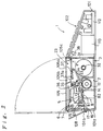
- Figure 2 is a cross-sectional view of Figure 1 taken along line II-II.
- the ink-jet printer 1 of the first embodiment is of the type called a "label printer" for performing a printing operation onto the surface of a tape whose back surface is covered with a releasable sheet via an adhesive layer.
- the ink-jet printer 1 has a thin casing 101 in the form of a generally rectangular prism.
- the front part of the upper plate of the casing 101 forms an operation control panel 102.
- Various keys such as a print button 103 for starting a printing operation and a power switch button 104 are disposed on the operation control panel 102.
- a lid 105 is disposed on the top of the rear part of the casing 101. The lid 105 can be opened and closed by means of rotation about the rear end. By pressing a lid open-close button 106 disposed on the operation control panel 102, a lock is released and the lid 105 may be opened so that the inside of the casing 101 can be seen from the top side of the ink-jet printer 1.
- Beneath the lid 105 is a mounting part 23 in which a tape cartridge 3, described below, can be mounted.
- the tape cartridge 3 can be mounted into or removed from the mounting part 23 when the lid 105 is open.
- the lid 105 has a transparent window 105a through which a user can see whether a tape cartridge 3 is mounted.
- a liquid crystal display unit 107 for displaying character information input via the keys on the operation control panel 102 is disposed in an area adjacent to the lid 105.
- a tape outlet 101b is formed in a rear side 101a of the casing 101 so that a printed tape may be carried out through the tape outlet 101b.
- the tape is guided by a guide plate 108.
- a power supply 112 and a battery 113 such as a nickel-cadmium battery are disposed inside of the casing 101 below the operation control panel 102.
- Figure 3 is a schematic diagram illustrating the main elements of the ink-jet printer 1 disposed inside the casing 101.
- reference numeral 2 denotes a base on which the elements are mounted, wherein the base 2 is placed on the bottom of the casing 101.
- the tape cartridge 3, three ink tanks 4 (4C, 4M, 4Y), and an ink-jet print head 5 are disposed on the base 2.
- the print head 5 is held on a head carriage 6.
- the head carriage 6 is supported by a lead screw 7 extending between right side-plate 22 and left side-plate 21 of the base 2.
- the carriage 6 is also supported by a guide axis (not shown) disposed in parallel to the lead screw 7 so that the carriage 6 can move left and right (along the lead screw) without rotation. That is, if the lead screw 7 is rotated, the head carriage 6 and the print head 5 held by the head carriage 6 move to the right or to the left in the directions (the first directions) denoted by arrows A and B in Figure 3.
- a tape guide element 8 is disposed at the center of the movement range of the print head 5 in such a manner that the tape guide element 8 faces the print head 5.
- the tape guide element 8 is an element corresponding to a platen disposed facing a print head of a printer such as a thermal printer, and the tape guide element 8 defines a printing position of the print head 5.
- the tape guide element 8 forms an excess ink capturing means.
- the top surface of the guide element 8 of the first embodiment comprises an ink filter 81 capable of capturing ink wherein the captured ink can pass through the filter.
- the ink filter 81 may be made of, for example, stainless steel in the form of a mesh.
- the ink filter 81 is attached to the surface of an ink absorber 82 in the form of a rectangular prism of an ink absorbing material.
- the ink captured on the surface of the guide element 8 passes through the ink filter 81 and is then absorbed by the ink absorber 82.
- a head capping mechanism 9 is disposed between the guide element 8 and the right side-plate 22.
- the head capping mechanism 9 is located at a position beyond at one end of the path along which the print head 5 moves during a printing operation.
- the print head 5 moves to the head capping mechanism 9 and is held there in a state in which the print head 5 is capped by a cap face 91 of the capping mechanism 9.
- an ink pump 11 which may be operated manually before starting a printing operation so as to forcibly supply ink from the ink tanks 4 to the print head 5.
- Figure 4 illustrates the layout, as seen from above, of the main elements of the ink-jet printer 1 according to the first embodiment. Referring to Figure 4 as well as other figures, the main elements of the ink-jet printer 1 of the present embodiment will be described below in detail.
- the tape cartridge 3 includes a case 31, a core axis 32 accommodated in the case 31 in such a manner that the core axis 32 can rotate, and a tape T having a width W1 wherein the tape T is wound around the core 32.
- the upper part of one face of the case 31 protrudes toward the rear face of the ink-jet printer 1.
- a tape feeder including a tape guide 33 made of PET (polyethylene) film and a tape pressing roller 34 which is pressed against the surface of the tape guide 33 by a constant elastic force provided by a coil spring 36.
- a supporting element 35 for supporting the tape pressing roller 34 is disposed on a side wall of the case 31 via the coil spring 36 in such a manner that the supporting element 35 can move up and down relative to the tape guide 33.
- the supporting element 35 is coupled to a lever 37.
- the lever 37 has an upper end face 37a protruding outside the case 31 of tape cartridge 3 on the upper side of the case 31. When the upper end face 37a is pushed downward, the tape pressing roller 34 is pressed toward the tape guide 33.
- On the upper surface of the case 31 are six indicators 38 for indicating the width of the tape T inside the case.
- the tape cartridge 3 is removably mounted in the mounting part 23.
- a tape feeding roller 12 is disposed just below the tape guide 33.
- the roller 12 has alternating portions of large diameter and small diameter.
- the lid 105 is disposed just above the tape cartridge 3 so that the tape cartridge can be mounted or removed when the lid 105 is open.
- the source of the recording medium essentially comprises the tape cartridge 3 in which the tape T is accommodated.
- the lid 105 has a pushing element 105b by which the upper end face 37a of the lever 37 is pushed down when the lid 105 is closed.
- the lid 105 which faces the tape width indicators 38 formed on the upper surface of the case 31 of the tape cartridge 3, is provided with detectors 105c for detecting the tape width W1 indicated by the indicators 38.
- the medium path of the tape T fed from the tape cartridge 3 will now be described.
- the tape T is fed out of the case 31 by means of the tape feeding roller 12.
- a plurality of tape guide strips 13 made of a PET film are disposed in such a manner that they are in contact with the surface of the short diameter portions of the tape feeding roller 12. These tape guide strips 13 ensure that the leading edge of the tape T is correctly guided in the forward direction of the medium path.
- a tape guide 14 made of stainless steel is disposed in the tape medium path ahead of the tape guide strips 13.
- the tape T is guided toward the printing position by the guide 14 and a guide disposed opposite the guide 14.
- the printing position is defined by the positions of the print head 5 and the guide element 8 disposed opposite the print head 5.
- the top surface of the guide element 8 is formed of the ink filter 81 attached to the surface of the ink absorber 82 composed of ink absorbing material. After passing the printing position, the tape T is pressed against a tape guide 16 by a tape pressing roller 15, and further passes a tape cutting position 17. Then, the tape T is carried out through the tape outlet 101b.
- a tape carrying motor 18 is disposed on the inner surface of the side-plate 22 of the base 2.
- the output shaft 18a of the motor is connected via a train of gears 181 to the end of the rotating axis 121 of the tape feeding roller 12.
- the train of gears 181 has the capability of switching the power. That is, if the head carriage 6 moves toward the side-plate 22 thereby pressing a protrusion 182 protruding inward from the side-plate 22, then the power transmission path is switched so that the power of the motor 18 is transmitted to the capping mechanism 9.
- the means for carrying the tape serving as the recording medium essentially comprises the tape feeding roller 12, the motor 18 serving as the power source for the tape feeding roller 12, and the train of gears 181 serving as the power transmission from the motor 18 to the roller 12.
- a head driving motor 19 is disposed on the inner surface of the left side-plate 21.
- the output shaft 19a of this motor is connected to the end of the lead screw 7 via a reduction mechanism 191 including a train of gears.
- the ink supplying means essentially comprises the ink tanks 4, three ink tubes 41 (41Y, 41M, 41C) through which inks are supplied from the ink tanks 4 to the print head 5, and the ink pump 11 by which the inks may be pumped manually.
- the three ink tanks 4C, 4M, and 4Y contain cyan, magenta, and yellow inks, respectively, with which a color printing operation is accomplished.
- the maximum allowable width of the tape T is W(max) as shown in Figure 4.
- the print head 5 is capable of performing a printing operation across the width of the tape (in the directions of the movement of the print head 5) over the maximum printing range W(p) which extends beyond the maximum allowable tape width W(max) on both right and left sides of the tape.
- the ink filter 81 forming the top surface of the guide element 8 is disposed over the maximum printing range.
- the tape has a width of W1, and the printing range of the print head 5 is set to W(p1) which includes the tape width W1.
- the width of the tape in the tape cartridge 3 is detected by reading the six indicators 38 disposed on the upper surface of the case 31.
- the indication of the tape width is possible for example by opening corresponding indicators 38.
- the tape width is determined by detecting which, if any, of the indicators 38 are open using mechanical or optical sensors forming the detectors 105c.
- FIG. 6 is a block diagram illustrating a control system of the ink-jet printer 1 according to the first embodiment.
- reference numeral 100 denotes a control circuit constructed with a microcomputer.
- An input unit 110 including the keys disposed on the operation control panel 102 of the ink-jet printer 1 is connected to respective inputs of the control circuit 100.
- the detector 105c for detecting the tape width is connected to respective inputs of the control circuit 100.
- Outputs of the control circuit 100 are connected to the display unit 107 such as a liquid crystal display device for displaying various information, a printer controller 140 for control the printing operation performed by the print head 5, and motor drivers 150 and 160 for control and driving the motors 18 and 19.
- the printing range is set to a value corresponding to the width of the tape in the tape cartridge 3, and a printing operation such as a solid printing operation is performed as will be described later.
- the control circuit 100 serves as the central part of the control system for the printing and driving means.
- the printing range is set to W(p1) which is greater than the width W1 of the tape.
- the motor 18 is driven so that the tape feeding roller 12 is rotated, thereby feeding the tape T from the tape cartridge 3 toward the printing position.
- the motor 19 rotates the lead screw 7 thereby moving the print head 5 via the carriage 6.
- the printing operation is performed over a range greater than the width W1 of the tape, thereby allowing the printing operation to occur across the entire width of the tape T.
- ink droplets ejected from the print head 5 before the print head 5 reaches the edge T1 of the tape T and after the print head 5 has passed the edge T2 of the tape T, travel toward the guide element 8 without striking the tape T.
- the guide element 8 since the ink filter 81 of the guide element 8 is disposed over the entire printing range, the ejected ink droplets are captured by the ink filter 81 and do not reach the other parts.
- the guide element 8 also comprises the ink absorber 82 which absorbs the ink droplets that have reached the surface and passed through the ink filter 81. In this way, the ink droplets are trapped via the surface of the guide element 8 and the following part of the tape T is not dirtied with ink droplets.
- the head carriage 6 moves in the direction denoted by the arrow B until it returns to a position near the left side-plate 21 as shown in Figure 4. Then a rotary cutter 61 on the carriage 6 is driven as the carriage 6 is moved again in the direction denoted by the arrow A with the cutter 61 remaining in the projected position.
- the tape T may be cut at a point along the length of the tape T after, on or before the position of the printing.
- the roller 12 may be rotated by the motor 18 in the opposite direction so that the new leading edge of the tape T at the cut returns to a position immediately prior to the printing position. Furthermore, the carriage 6 moves to the right side-plate 22 so that the protrusion 182 is pressed outward by the side face of the carriage 6 thereby cutting the linkage between the motor 18 and the tape feeding roller 12. As a result, the roller 12 stops its rotation and the capping mechanism 9 is then driven so that the print head 5 is capped.
- the tape T (with its leading edge located at the position immediately prior to the printing position) is wound backward into the tape case 31 until the leading edge of the tape returns to the position between the pressing roller 34 and the tape guide 33 forming the tape feeding mechanism.
- the printing range is set accordingly. For example, if the specified region is bounded by the left edge of the tape T, the printing range is set so that the printing operation starts at a position prior to the left edge of the tape T. If the specified region is bounded by the right edge of the tape T, the printing range is set so that the printing operation stops after the print head has passed the right edge of the tape T.
- an ink-jet printer is able to perform a solid printing operation across the entire width of a tape and/or along the entire length of a tape.
- the printing operation is started slightly before the leading edge of the tape reaches the printing position of the print head 5.
- the printing operation is continued until after the location that will become the trailing edge of the tape has passed the printing position.
- the tape is cut by rotary cutter 61 at the desired location for the trailing edge.
- Figures 7, 8, and 9 illustrate the main elements of a second embodiment of an ink-jet printer for performing a solid printing operation on a large recording medium such as a poster, although the second embodiment may also be applied in an ink-jet printer for printing a relatively small recording medium such as a tape as in the first embodiment.
- the ink-jet printer 200 according to the second embodiment is very similar to that of the first embodiment except that the recording medium is in the form of a cut sheet such as a poster, the carriage mechanism of the print head is driven by a belt and pulley rather than gears and a lead screw, and the excess ink capturing means is constructed on the paper guide in a different manner.
- the recording medium is in the form of a cut sheet such as a poster
- the carriage mechanism of the print head is driven by a belt and pulley rather than gears and a lead screw
- the excess ink capturing means is constructed on the paper guide in a different manner.
- a carriage 202 holds and carries not only a print head at its lower part but also ink cartridges 203Y, 203M, and 203C containing three color inks.
- One side of the carriage 202 is supported by a carriage guide plate 204.
- the other side of the carriage 202 is supported by carriage guide shaft 206 extending parallel to the guide plate 204.
- the carriage 202 is able to move in both directions across the width of recording medium 205, along the surface of the carriage guide plate 204.
- the carriage 202 is connected to a timing belt 209 which travels between a driving pulley 207 and a driven pulley 208.
- the driving pulley 207 is connected to the output shaft of a carriage motor 210 so that the print head held by the carriage 202 can be moved by the motor 210 in both directions across the width of the recording medium 205.
- a feeding roller 221 and a pair of pressing rollers 222 and 223 which are pressed against the surface of the feeding roller 221.
- the recording medium 205 is carried through these elements toward the printing position of the print head.
- a guiding element for guiding the recording medium 205 is disposed below the print head over a range including at least the reciprocating movement range of the print head.
- the guiding element is provided with an excess ink capturing mechanism 211.
- the excess ink capturing mechanism 211 includes: a captured ink reservoir 212 in the form of a rectangular box having a width sufficiently greater than the width of the recording medium used; an ink absorbing material 213 disposed inside the captured ink reservoir 212; and a plurality of guide ribs 214 for guiding the recording medium.
- the captured ink reservoir 212 comprises a bottom plate 212a and front, rear, left, and right side walls 212e, 212b, 212c and 212d, respectively, rising from the periphery of the bottom plate 212a, wherein the upper side of the reservoir 212 is open.
- the ink absorbing material 213 is disposed on the bottom plate 212a of the captured ink reservoir 212 in such a manner that the ink absorbing material 213 extends along the left side wall 212c, the rear side wall 212b, and the right side wall 212d.
- the vertically-protruding guide ribs 214 in the form of a sector are attached to the bottom plate 212a, are displaced at equal intervals across the width of the bottom plate 212a and surrounded by the ink absorbing material 213 and the front side wall 212e of the captured ink reservoir 212.
- the upper ends of these ribs 214 extend slightly above the side walls of the captured ink reservoir 212 so that the recording medium 205 can be guided by the upper end portions of these ribs 214 when the recording medium 205 passes over the captured ink reservoir 212.
- An ink exhaust means is provided at the bottom plate 212a of the captured ink reservoir 212.
- pipes 215 are connected to the captured ink reservoir 212 in such a manner that these pipes may carry away ink that is absorbed by the ink absorbing material 213.
- the other ends of the pipes 215 are connected to a suction pump (not shown) which facilitates the removal of ink from the ink absorbing material 213.
- the ink absorbing material 213 includes the printing range W(p) which is set to a value greater than the maximum medium width W(max) and which extends beyond the left and right sides, 205L and 205R, respectively, of the recording medium 205 as shown in Figure 9.
- W(p) the printing range W(p) which is set to a value greater than the maximum medium width W(max) and which extends beyond the left and right sides, 205L and 205R, respectively, of the recording medium 205 as shown in Figure 9.
- the printing operation is started when the print head has come to a position slightly prior to the left edge 205L of the recording medium 205, and it is continued until the print head has passed the right edge 205R of the recording medium 205, as is done in the first embodiment.
- the ink droplets which do not arrive at the surface of the recording medium 205 will reach the surface of the ink absorbing material 213 in the excess ink capturing mechanism 211 and will be absorbed by the ink absorbing material 213. This ensures that subsequent recording media are not dirtied with ink.
- the printing position of the print head is denoted by line P.
- the printing position is set at the center of the width of the ink absorbing material in the medium movement direction (that is, at the center between lines L1 and L2).
- This technique ensures that the solid printing operation is performed without producing a non-printed area at the leading and trailing edges (upstream and downstream edges) of the recording medium 205. Furthermore, during such a solid printing operation, the ink droplets which travel without reaching the recording medium are captured by the ink absorbing material disposed at the back side of the recording medium and absorbed into it. Therefore, this technique avoids the problem that the ink droplets are deposited on undesired portions and the following recording medium is made dirty with the deposited ink.
- the ink absorbing material 213 is distributed along the three side walls 212b, 212c and 212d. In an alternative embodiment, the ink absorbing material 213 is distributed across the entire bottom plate 212a so that the ink absorbing material 213 has a rectangular shape. In yet another embodiment, the ink absorbing material 213 has a rectangular shape with a hole at its center. However, it is more economical and desirable to dispose the ink absorbing material 213 in only the areas which ink droplets can reach.
- the width of the recording medium 205 is detected by an optical sensor 231 attached to a side of the carriage 202.
- the optical sensor 231 receives light reflected from the surface of the recording medium 205 and is able to detect the edges of the recording medium 205 from changes in the amount of light received when it moves past the edges, thereby detecting the width of the recording medium used.
- the printing range is set to extend beyond the medium on both sides.
- An optical sensor 231 may be attached to each side of the carriage 202 or, alternatively, only one optical sensor 231 may be employed. If only one optical sensor 231 is used, the carriage is moved across the entire width of the recording medium 205 before starting a printing operation so that both edges can be detected.
- Figure 10 illustrates a third embodiment of an ink-jet printer with an ink capturing mechanism based on a modification of the second embodiment.
- this modified ink capturing mechanism 311 comprises a captured ink reservoir 312 and an ink absorbing material 313 disposed in the captured ink reservoir 312.
- the excess ink capturing mechanism 311 in the third embodiment is adapted to move with the print head carriage 315.
- the excess ink capturing mechanism 311 of the third embodiment is supported by a carriage 314 which is in turn supported by a pair of guide shafts 316 and 317 that are parallel to each other, allowing the carriage 314 to move in both directions along the guide shafts.
- the carriage 314 is connected to a timing belt 318 which travels between a driving pulley 319 and a driven pulley 320.
- the driving pulley 319 is connected to the output shaft of a carriage motor 322 via a train of reduction gears 321.
- the head carriage 315 for holding and carrying the print head is supported so that it can move in both directions along a guide plate 332 and a guide shaft 333, as in the second embodiment.
- the head carriage 315 is connected to a timing belt 336 which travels between a driving pulley 334 and a driven pulley 335.
- the driving pulley 334 is connected to the output shaft of the carriage motor 322 via a train of gears 337.
- the two timing belts 318 and 336 are driven in synchronization with each other so that both the excess ink capturing mechanism 311 and the print head may move together in both directions.
- a guide element 361 having a width greater than the maximum possible printing range is disposed between the head carriage 315 and the excess ink capturing mechanism 311 in such a manner that an end portion of the guide element 361 extends upstream in the medium path of medium 362 movement by a predetermined amount.
- the excess ink capturing mechanism 311 moves together with the print head, there is no need to distribute the ink absorbing material over a range including the entire stroke of the print head unlike that required in the second embodiment. This allows a reduction in the size of the excess ink capturing mechanism.
- the excess ink capturing mechanism 311 that moves together with the print head is generally preferable to the excess ink capturing mechanism 211 which is formed across the entire width of the recording medium as in the second embodiment.
- the ink absorbing material 313 be connected to an ink tank 343 via a pipe 341 so that the accumulated ink may be removed from the ink capturing mechanism 311 into the ink tank 343 by means of a suction pump 342.
- the present invention is not limited to application in a color printer.
- the present invention may also be applied in an ink-jet printer having only one ink tank for ink of any color such as black.
- a white ink in addition to the three colors cyan, magenta, and yellow.
- This allows high-quality reproduction for each color even when printing is performed onto a recording medium having a color other than white.
- Colors which can be created by mixing three ink colors (cyan, magenta, and yellow) are limited to red, green, blue, and black.
- Other colors are obtained by means of area gradation based on a dither method. As a result, these other colors are poor in quality compared to the colors that can be produced by means of normal printing.
- it is impossible to create white by mixing cyan, magenta, and yellow.
- a white color ink is employed in addition to the above three colors, the problems described above can be avoided.
- four color inks cyan, magenta, yellow and white
- the color of the recording medium can be easily changed by mounting a tape cartridge 3 having the tape T of the desired color.
Abstract
Description
- The present invention relates to a printer having a print head of the ink-jet type.
- Various types of ink-jet printers are known in the art. In these types of printers, maximum printing areas are defined for individual standard sizes of recording media. In general, the maximum printing area is defined in terms of top-, bottom-, right- and left-margins so that the printing area is smaller than the size of a recording medium by the amount defined by the margins. Each margin is set to a value in the range from 3 mm to 13 mm, and no printer has been proposed which can perform a printing operation across the entire area including these margins.
- In a known small-sized ink-jet printer, a tape having a color selected from various colors can be employed as the recording medium. Further, color printing can be performed onto the selected tape. In a small-sized color ink-jet printer of this type, a color printing operation is performed onto a tape with inks supplied to ink-jet print heads from ink tanks for color inks of cyan (C), magenta (M), and yellow (Y).
- As for the tape, a tape is known which has a releasable sheet covering the back surface of the tape via an adhesive layer. After completion of printing, the tape is cut away into a piece having a proper size. Then the releasable sheet is removed and the tape is stuck onto a desired object. The printer of the type designed to perform a printing operation onto a tape is called a label printer and is now popular in the market.
- When the conventional ink-jet printer is used to attempt a solid printing operation across the entire area of a recording medium such as a tape, no printing can be done near the edges of the tape in the margins mentioned above.
- To perform a solid printing operation by moving a print head in a reciprocating fashion across the width of a tape without producing a non-printed area at edges of the tape, a printing operation must be started at one end of the width of the tape and must be stopped at the other end of the width of the tape. However, it is generally difficult to drive the print head so that the printing operation is started precisely at one edge of the width of the tape and is stopped precisely at the other edge of the width of the tape. This difficulty arises from deviations in the tape carrying position in a direction across the width of the tape, or from a timing error between the ink ejection operation and the movement of the print head. If the printing operation is not controlled precisely, for example, if the start of the printing operation is delayed from the time at which the print head is at the edge of the width of the tape, a non-printed area is produced in a region near the edge of the width of the tape.
- In view of the above, it is an object of the present invention to provide an ink-jet printer capable of performing a printing operation throughout the entire area of a selected region having at least one boundary at an edge of a recording medium such as a tape. The selected region may extend across the entire width and/or along the entire length of a medium such as a tape (hereafter, this printing operation mode is referred to as "solid printing").
- This object is achieved with an ink-jet printer as claimed in
claim 1. Preferred embodiments are subject-matter of the dependent claims. - An advantageous feature of one embodiment incorporating the present invention provides an ink-jet printer that does not make a recording medium dirty with ink droplets which are deposited on a guide element or the like during a solid printing operation.
- A further advantage may be realized by using the present invention with a particular recording medium suitable for use with an ink-jet printer capable of performing a solid printing operation.
- The present invention provides an ink-jet printer in which a print head is controlled so as to perform a printing operation in an area which extends beyond the leading or trailing edge of a recording medium, and/or which extends beyond either side-edge of a recording medium such as a tape (hereafter, this printing operation is referred to as "passing-over"). With this arrangement, the print head is driven in such a manner that the printing operation is performed continuously until the print head has moved past the edge of the recording medium thereby accomplishing the solid printing operation.
- In another embodiment, an ink-jet printer incorporating the present invention also has excess ink capturing means for capturing the ink droplets which are ejected from the print head when the print head is at a passing-over position. In such an embodiment, it is possible to avoid the deposition of ejected ink droplets onto a guide element disposed facing the print head thereby preventing the following recording medium from being dirtied by the deposited ink.
- The printing range in the first direction, that is, the range in which a solid printing operation is possible, is for example across the width of the recording medium perpendicular to the direction along which the recording medium is carried. Alternatively, the first direction may be a direction along the length of the recording medium parallel to the direction along which the recording medium is carried. Furthermore, it is also possible to set the printing range in such a manner that, in addition to the first direction, the printing range also includes an area which is deviated outward from an edge of the recording medium in a second direction different from the above first direction. For example, if the first and second directions are perpendicular to each other, it is possible to accomplish a solid printing operation over the entire area of a recording medium.
- In another embodiment, the ink-jet printer further includes excess ink capturing means for capturing the ink droplets which are ejected from the print head when the print head is located at a position deviated outward from the edge of the recording medium. The excess ink capturing means is disposed at a location facing the print head via the carrying path (referred to as "medium path" in the following) along which the recording medium supplied is carried, and the excess ink capturing means is formed over the entire range including the printing range of the print head, wherein the printing range includes an area outside at least one edge of the recording medium. To achieve such an embodiment, the excess ink capturing means is disposed on a guide element which defines the position of printing performed by the print head onto the recording medium being carried. In this case, the surface of the guide element facing the recording medium can be formed of a stainless steel mesh.
- Furthermore, it is desirable that the excess ink capturing means include ink exhausting means for exhausting captured ink, thereby preventing the excess ink capturing means from becoming full of the captured ink and maintaining the capability of capturing excess ink droplets.
- In the case of an ink-jet printer for performing a printing operation onto a large-size recording medium, it is not economical to dispose the excess ink capturing means across the entire width or along the entire length of a large-size recording medium. Furthermore, such an excess ink capturing means would require considerable space. This problem can be avoided if the excess ink capturing means is adapted to move with the print head. This construction may also be applied in a printer suitable for only a small-size recording medium.
- A tape having considerable length and constant width can be employed as the recording medium. In this case, a tape cartridge can be employed as the recording medium source in which the tape may be wound in the form of a roll and wherein the tape cartridge is removably mounted in the ink-jet printer. Such a tape cartridge can accommodate various tapes having different widths. Therefore, to make it possible to correctly set the printing range of the solid printing operation corresponding to the width of a tape used, the tape cartridge further includes width indication means for indicating the width of the tape in the tape cartridge; the control means includes reading means for reading the width indicated by the width indication means; and the printing range of the print head in the first direction is set according to the width read by the reading means.
- Furthermore, a transparent medium such as a transparent tape may be employed as the recording medium.
- In an ink-jet printer incorporating the present invention, when a solid printing operation is performed across the entire width or along the entire length of a recording medium, a control means sets the printing range to include the entire width or the entire length of the recording medium so that the printing operation starts at a position prior to the starting edge of the recording medium and stops at a position beyond the ending edge of the recording medium.
- The ink droplets which are ejected from the print head before the print head reaches the starting edge of the recording medium and after the print head has passed the ending edge are captured by the excess ink capturing means. Therefore, it is possible to prevent the ink droplets ejected during the extended printing operation from depositing for example on the surface disposed facing the print head, and thus it is possible to prevent the following recording medium from becoming dirty with the deposited ink.
- Fig. 1
- is a perspective view illustrating the external appearance of an ink-jet printer according to a first embodiment of the present invention.
- Fig. 2
- is a cross-sectional view of Figure 1 taken along line II-II.
- Fig. 3
- is a schematic diagram illustrating the main elements of the printer shown in Figure 1.
- Fig.4
- is a schematic diagram illustrating the main elements, seen from above, of the ink-jet printer of Figure 1.
- Fig. 5
- is a schematic diagram illustrating a paper guide element used in the printer shown in Figure 1.
- Fig. 6
- is a simplified block diagram illustrating a control system of the ink-jet printer of Figure 1.
- Fig. 7
- is a schematic diagram illustrating the main elements of an ink-jet printer according to a second embodiment of the present invention.
- Fig. 8
- is a schematic diagram illustrating a captured ink reservoir used in the printer of Figure 7.
- Fig. 9
- is a schematic diagram illustrating the printing operation of the printer shown in Figure 7.
- Fig. 10
- is a schematic diagram illustrating the main elements of a modified ink-jet printer based on the printer of Figure 7.
- Referring to the drawings, embodiments of the present invention will be described below.
- Figure 1 is a perspective view illustrating the external appearance of a first embodiment of an ink-jet printer according to the present invention. Figure 2 is a cross-sectional view of Figure 1 taken along line II-II. The ink-
jet printer 1 of the first embodiment is of the type called a "label printer" for performing a printing operation onto the surface of a tape whose back surface is covered with a releasable sheet via an adhesive layer. - Referring to Figures 1 and 2, the ink-
jet printer 1 has athin casing 101 in the form of a generally rectangular prism. The front part of the upper plate of thecasing 101 forms anoperation control panel 102. Various keys such as aprint button 103 for starting a printing operation and apower switch button 104 are disposed on theoperation control panel 102. Alid 105 is disposed on the top of the rear part of thecasing 101. Thelid 105 can be opened and closed by means of rotation about the rear end. By pressing a lid open-close button 106 disposed on theoperation control panel 102, a lock is released and thelid 105 may be opened so that the inside of thecasing 101 can be seen from the top side of the ink-jet printer 1. - Beneath the
lid 105 is a mountingpart 23 in which atape cartridge 3, described below, can be mounted. Thus, thetape cartridge 3 can be mounted into or removed from the mountingpart 23 when thelid 105 is open. Thelid 105 has atransparent window 105a through which a user can see whether atape cartridge 3 is mounted. A liquidcrystal display unit 107 for displaying character information input via the keys on theoperation control panel 102 is disposed in an area adjacent to thelid 105. - A
tape outlet 101b is formed in arear side 101a of thecasing 101 so that a printed tape may be carried out through thetape outlet 101b. When the printed tape is carried out through thetape outlet 101b, the tape is guided by aguide plate 108. Apower supply 112 and abattery 113 such as a nickel-cadmium battery are disposed inside of thecasing 101 below theoperation control panel 102. - Figure 3 is a schematic diagram illustrating the main elements of the ink-
jet printer 1 disposed inside thecasing 101. In Figure 3,reference numeral 2 denotes a base on which the elements are mounted, wherein thebase 2 is placed on the bottom of thecasing 101. Thetape cartridge 3, three ink tanks 4 (4C, 4M, 4Y), and an ink-jet print head 5 are disposed on thebase 2. Theprint head 5 is held on ahead carriage 6. Thehead carriage 6 is supported by alead screw 7 extending between right side-plate 22 and left side-plate 21 of thebase 2. Thecarriage 6 is also supported by a guide axis (not shown) disposed in parallel to thelead screw 7 so that thecarriage 6 can move left and right (along the lead screw) without rotation. That is, if thelead screw 7 is rotated, thehead carriage 6 and theprint head 5 held by thehead carriage 6 move to the right or to the left in the directions (the first directions) denoted by arrows A and B in Figure 3. - A
tape guide element 8 is disposed at the center of the movement range of theprint head 5 in such a manner that thetape guide element 8 faces theprint head 5. Thetape guide element 8 is an element corresponding to a platen disposed facing a print head of a printer such as a thermal printer, and thetape guide element 8 defines a printing position of theprint head 5. - In the first embodiment, the
tape guide element 8 forms an excess ink capturing means. As shown in Figure 5, the top surface of theguide element 8 of the first embodiment comprises anink filter 81 capable of capturing ink wherein the captured ink can pass through the filter. Theink filter 81 may be made of, for example, stainless steel in the form of a mesh. Theink filter 81 is attached to the surface of anink absorber 82 in the form of a rectangular prism of an ink absorbing material. Thus, the ink captured on the surface of theguide element 8 passes through theink filter 81 and is then absorbed by theink absorber 82. - Referring again to Figure 3, a
head capping mechanism 9 is disposed between theguide element 8 and the right side-plate 22. Thehead capping mechanism 9 is located at a position beyond at one end of the path along which theprint head 5 moves during a printing operation. When theprint head 5 is not in use, theprint head 5 moves to thehead capping mechanism 9 and is held there in a state in which theprint head 5 is capped by acap face 91 of thecapping mechanism 9. At the side of thetape cartridge 3 is anink pump 11 which may be operated manually before starting a printing operation so as to forcibly supply ink from theink tanks 4 to theprint head 5. - Figure 4 illustrates the layout, as seen from above, of the main elements of the ink-
jet printer 1 according to the first embodiment. Referring to Figure 4 as well as other figures, the main elements of the ink-jet printer 1 of the present embodiment will be described below in detail. - The
tape cartridge 3 includes acase 31, acore axis 32 accommodated in thecase 31 in such a manner that thecore axis 32 can rotate, and a tape T having a width W1 wherein the tape T is wound around thecore 32. The upper part of one face of thecase 31 protrudes toward the rear face of the ink-jet printer 1. Within this protruding region is formed a tape feeder including atape guide 33 made of PET (polyethylene) film and atape pressing roller 34 which is pressed against the surface of thetape guide 33 by a constant elastic force provided by a coil spring 36. When thetape cartridge 3 is initially loaded into the ink-jet printer 1, the leading edge of the tape T is placed between thetape guide 33 and thetape pressing roller 34. A supportingelement 35 for supporting thetape pressing roller 34 is disposed on a side wall of thecase 31 via the coil spring 36 in such a manner that the supportingelement 35 can move up and down relative to thetape guide 33. The supportingelement 35 is coupled to alever 37. Thelever 37 has anupper end face 37a protruding outside thecase 31 oftape cartridge 3 on the upper side of thecase 31. When theupper end face 37a is pushed downward, thetape pressing roller 34 is pressed toward thetape guide 33. On the upper surface of thecase 31 are sixindicators 38 for indicating the width of the tape T inside the case. - The
tape cartridge 3 is removably mounted in the mountingpart 23. In the mountingpart 23, atape feeding roller 12 is disposed just below thetape guide 33. Theroller 12 has alternating portions of large diameter and small diameter. As described above, thelid 105 is disposed just above thetape cartridge 3 so that the tape cartridge can be mounted or removed when thelid 105 is open. - In this first embodiment, the source of the recording medium essentially comprises the
tape cartridge 3 in which the tape T is accommodated. - As can be seen from Figure 2, the
lid 105 has a pushingelement 105b by which theupper end face 37a of thelever 37 is pushed down when thelid 105 is closed. Thelid 105, which faces thetape width indicators 38 formed on the upper surface of thecase 31 of thetape cartridge 3, is provided withdetectors 105c for detecting the tape width W1 indicated by theindicators 38. - The medium path of the tape T fed from the
tape cartridge 3 will now be described. The tape T is fed out of thecase 31 by means of thetape feeding roller 12. A plurality of tape guide strips 13 made of a PET film are disposed in such a manner that they are in contact with the surface of the short diameter portions of thetape feeding roller 12. These tape guide strips 13 ensure that the leading edge of the tape T is correctly guided in the forward direction of the medium path. Atape guide 14 made of stainless steel is disposed in the tape medium path ahead of the tape guide strips 13. The tape T is guided toward the printing position by theguide 14 and a guide disposed opposite theguide 14. The printing position is defined by the positions of theprint head 5 and theguide element 8 disposed opposite theprint head 5. The top surface of theguide element 8 is formed of theink filter 81 attached to the surface of theink absorber 82 composed of ink absorbing material. After passing the printing position, the tape T is pressed against atape guide 16 by atape pressing roller 15, and further passes atape cutting position 17. Then, the tape T is carried out through thetape outlet 101b. - The driving force transmission system relating to the
tape feeding roller 12 and thehead carriage 6 for holding theprint head 5 will now be described. As illustrated in Figures 3 and 4, atape carrying motor 18 is disposed on the inner surface of the side-plate 22 of thebase 2. Theoutput shaft 18a of the motor is connected via a train ofgears 181 to the end of therotating axis 121 of thetape feeding roller 12. In this first embodiment, the train ofgears 181 has the capability of switching the power. That is, if thehead carriage 6 moves toward the side-plate 22 thereby pressing aprotrusion 182 protruding inward from the side-plate 22, then the power transmission path is switched so that the power of themotor 18 is transmitted to thecapping mechanism 9. In this first embodiment, the means for carrying the tape serving as the recording medium essentially comprises thetape feeding roller 12, themotor 18 serving as the power source for thetape feeding roller 12, and the train ofgears 181 serving as the power transmission from themotor 18 to theroller 12. - A
head driving motor 19 is disposed on the inner surface of the left side-plate 21. The output shaft 19a of this motor is connected to the end of thelead screw 7 via areduction mechanism 191 including a train of gears. - The ink supplying means essentially comprises the
ink tanks 4, three ink tubes 41 (41Y, 41M, 41C) through which inks are supplied from theink tanks 4 to theprint head 5, and theink pump 11 by which the inks may be pumped manually. The threeink tanks - In the ink-
jet printer 1 of the first embodiment, the maximum allowable width of the tape T is W(max) as shown in Figure 4. Theprint head 5 is capable of performing a printing operation across the width of the tape (in the directions of the movement of the print head 5) over the maximum printing range W(p) which extends beyond the maximum allowable tape width W(max) on both right and left sides of the tape. Theink filter 81 forming the top surface of theguide element 8 is disposed over the maximum printing range. - In the example shown in Figure 4, the tape has a width of W1, and the printing range of the
print head 5 is set to W(p1) which includes the tape width W1. - The width of the tape in the
tape cartridge 3 is detected by reading the sixindicators 38 disposed on the upper surface of thecase 31. The indication of the tape width is possible for example by opening correspondingindicators 38. The tape width is determined by detecting which, if any, of theindicators 38 are open using mechanical or optical sensors forming thedetectors 105c. - Figure 6 is a block diagram illustrating a control system of the ink-
jet printer 1 according to the first embodiment. In Figure 6,reference numeral 100 denotes a control circuit constructed with a microcomputer. Aninput unit 110 including the keys disposed on theoperation control panel 102 of the ink-jet printer 1 is connected to respective inputs of thecontrol circuit 100. Thedetector 105c for detecting the tape width is connected to respective inputs of thecontrol circuit 100. Outputs of thecontrol circuit 100 are connected to thedisplay unit 107 such as a liquid crystal display device for displaying various information, aprinter controller 140 for control the printing operation performed by theprint head 5, andmotor drivers motors control circuit 100 according to a control program stored in a ROM of thecontrol circuit 100, the printing range is set to a value corresponding to the width of the tape in thetape cartridge 3, and a printing operation such as a solid printing operation is performed as will be described later. In the first embodiment, thecontrol circuit 100 serves as the central part of the control system for the printing and driving means. - In the ink-
jet printer 1 constructed in the above-described manner, a solid printing operation for printing on the tape T across the entire width of the tape is performed in a manner which will now be described. In the example illustrated in Figure 4, the printing range is set to W(p1) which is greater than the width W1 of the tape. Themotor 18 is driven so that thetape feeding roller 12 is rotated, thereby feeding the tape T from thetape cartridge 3 toward the printing position. In synchronization with the carrying operation of the tape T, themotor 19 rotates thelead screw 7 thereby moving theprint head 5 via thecarriage 6. When theprint head 5, moving in the direction denoted by the arrow A shown in Figure 4, reaches the printing position T0 prior to reaching the left edge T1 of the tape T, a printing operation is started. The printing operation continues in the forward direction (along the direction of the arrow A) and is stopped when theprint head 5 reaches the printing position T3 after passing the right edge T2 of the tape T. - In the ink-
jet printer 1 of the first embodiment, as described above, the printing operation is performed over a range greater than the width W1 of the tape, thereby allowing the printing operation to occur across the entire width of the tape T. - In the printing operation described above, ink droplets, ejected from the
print head 5 before theprint head 5 reaches the edge T1 of the tape T and after theprint head 5 has passed the edge T2 of the tape T, travel toward theguide element 8 without striking the tape T. In this first embodiment, since theink filter 81 of theguide element 8 is disposed over the entire printing range, the ejected ink droplets are captured by theink filter 81 and do not reach the other parts. Furthermore, in the first embodiment, theguide element 8 also comprises theink absorber 82 which absorbs the ink droplets that have reached the surface and passed through theink filter 81. In this way, the ink droplets are trapped via the surface of theguide element 8 and the following part of the tape T is not dirtied with ink droplets. - After completion of a printing operation, the
head carriage 6 moves in the direction denoted by the arrow B until it returns to a position near the left side-plate 21 as shown in Figure 4. Then arotary cutter 61 on thecarriage 6 is driven as thecarriage 6 is moved again in the direction denoted by the arrow A with thecutter 61 remaining in the projected position. By controlling the forward movement of the tape T along the medium path after theprint head 5 has completed a printing operation and before therotary cutter 61 performs a cutting operation, the tape T may be cut at a point along the length of the tape T after, on or before the position of the printing. - After the cutting operation has completed, the
roller 12 may be rotated by themotor 18 in the opposite direction so that the new leading edge of the tape T at the cut returns to a position immediately prior to the printing position. Furthermore, thecarriage 6 moves to the right side-plate 22 so that theprotrusion 182 is pressed outward by the side face of thecarriage 6 thereby cutting the linkage between themotor 18 and thetape feeding roller 12. As a result, theroller 12 stops its rotation and thecapping mechanism 9 is then driven so that theprint head 5 is capped. - When the
lid 105 covering the mountingpart 23 is opened to replace thetape cartridge 3, the tape T (with its leading edge located at the position immediately prior to the printing position) is wound backward into thetape case 31 until the leading edge of the tape returns to the position between thepressing roller 34 and thetape guide 33 forming the tape feeding mechanism. - If a solid printing operation is performed in a specified region having a boundary at only one edge of the tape T, the printing range is set accordingly. For example, if the specified region is bounded by the left edge of the tape T, the printing range is set so that the printing operation starts at a position prior to the left edge of the tape T. If the specified region is bounded by the right edge of the tape T, the printing range is set so that the printing operation stops after the print head has passed the right edge of the tape T.
- As described above, an ink-jet printer according to the first embodiment is able to perform a solid printing operation across the entire width of a tape and/or along the entire length of a tape. As explained above, if it is desired to perform a solid printing operation at the leading edge of the tape, the printing operation is started slightly before the leading edge of the tape reaches the printing position of the
print head 5. On the other hand, if it is desired to perform a solid printing operation at the trailing edge of the tape, the printing operation is continued until after the location that will become the trailing edge of the tape has passed the printing position. The tape is cut byrotary cutter 61 at the desired location for the trailing edge. - Figures 7, 8, and 9 illustrate the main elements of a second embodiment of an ink-jet printer for performing a solid printing operation on a large recording medium such as a poster, although the second embodiment may also be applied in an ink-jet printer for printing a relatively small recording medium such as a tape as in the first embodiment.
- The ink-
jet printer 200 according to the second embodiment is very similar to that of the first embodiment except that the recording medium is in the form of a cut sheet such as a poster, the carriage mechanism of the print head is driven by a belt and pulley rather than gears and a lead screw, and the excess ink capturing means is constructed on the paper guide in a different manner. Thus, only those elements which are different from those in the previously described first embodiment will be described below. - Referring to Figure 7, a
carriage 202 holds and carries not only a print head at its lower part but alsoink cartridges carriage 202 is supported by acarriage guide plate 204. The other side of thecarriage 202 is supported bycarriage guide shaft 206 extending parallel to theguide plate 204. In this matter, thecarriage 202 is able to move in both directions across the width ofrecording medium 205, along the surface of thecarriage guide plate 204. Thecarriage 202 is connected to atiming belt 209 which travels between a drivingpulley 207 and a drivenpulley 208. The drivingpulley 207 is connected to the output shaft of acarriage motor 210 so that the print head held by thecarriage 202 can be moved by themotor 210 in both directions across the width of therecording medium 205. - At an upstream location in the medium path of the
recording medium 205, opposite thecarriage 202 by which the print head is held and carried, there are disposed afeeding roller 221 and a pair of pressingrollers roller 221. Therecording medium 205 is carried through these elements toward the printing position of the print head. - A guiding element for guiding the
recording medium 205 is disposed below the print head over a range including at least the reciprocating movement range of the print head. The guiding element is provided with an excessink capturing mechanism 211. As shown in Figure 8, the excessink capturing mechanism 211 includes: a capturedink reservoir 212 in the form of a rectangular box having a width sufficiently greater than the width of the recording medium used; anink absorbing material 213 disposed inside the capturedink reservoir 212; and a plurality ofguide ribs 214 for guiding the recording medium. The capturedink reservoir 212 comprises abottom plate 212a and front, rear, left, andright side walls bottom plate 212a, wherein the upper side of thereservoir 212 is open. Theink absorbing material 213 is disposed on thebottom plate 212a of the capturedink reservoir 212 in such a manner that theink absorbing material 213 extends along theleft side wall 212c, therear side wall 212b, and theright side wall 212d. The vertically-protrudingguide ribs 214 in the form of a sector are attached to thebottom plate 212a, are displaced at equal intervals across the width of thebottom plate 212a and surrounded by theink absorbing material 213 and thefront side wall 212e of the capturedink reservoir 212. The upper ends of theseribs 214 extend slightly above the side walls of the capturedink reservoir 212 so that therecording medium 205 can be guided by the upper end portions of theseribs 214 when therecording medium 205 passes over the capturedink reservoir 212. - An ink exhaust means is provided at the
bottom plate 212a of the capturedink reservoir 212. In the embodiment illustrated in the figures,pipes 215 are connected to the capturedink reservoir 212 in such a manner that these pipes may carry away ink that is absorbed by theink absorbing material 213. The other ends of thepipes 215 are connected to a suction pump (not shown) which facilitates the removal of ink from theink absorbing material 213. - According to this second embodiment, the
ink absorbing material 213 includes the printing range W(p) which is set to a value greater than the maximum medium width W(max) and which extends beyond the left and right sides, 205L and 205R, respectively, of therecording medium 205 as shown in Figure 9. To perform a solid a printing operation across the width ofrecording medium 205, the printing operation is started when the print head has come to a position slightly prior to the left edge 205L of therecording medium 205, and it is continued until the print head has passed theright edge 205R of therecording medium 205, as is done in the first embodiment. During such a printing operation, the ink droplets which do not arrive at the surface of therecording medium 205 will reach the surface of theink absorbing material 213 in the excessink capturing mechanism 211 and will be absorbed by theink absorbing material 213. This ensures that subsequent recording media are not dirtied with ink. - In the present embodiment, it is also possible to perform a solid printing operation in the direction of the movement of the
recording medium 205 without producing a non-printed area at the leading (205F) and trailing (205T) edges of therecording medium 205, as will be described below. In Figure 9, the printing position of the print head is denoted by line P. The printing position is set at the center of the width of the ink absorbing material in the medium movement direction (that is, at the center between lines L1 and L2). When theleading edge 205F of the recording medium has reached a position (upstream position) slightly prior to the line P, the printing operation with the print head is started. The printing operation is continued until the trailingedge 205T of the recording medium has moved slightly past the line P. This technique ensures that the solid printing operation is performed without producing a non-printed area at the leading and trailing edges (upstream and downstream edges) of therecording medium 205. Furthermore, during such a solid printing operation, the ink droplets which travel without reaching the recording medium are captured by the ink absorbing material disposed at the back side of the recording medium and absorbed into it. Therefore, this technique avoids the problem that the ink droplets are deposited on undesired portions and the following recording medium is made dirty with the deposited ink. - In the second embodiment described above, the
ink absorbing material 213 is distributed along the threeside walls ink absorbing material 213 is distributed across theentire bottom plate 212a so that theink absorbing material 213 has a rectangular shape. In yet another embodiment, theink absorbing material 213 has a rectangular shape with a hole at its center. However, it is more economical and desirable to dispose theink absorbing material 213 in only the areas which ink droplets can reach. In the second embodiment, only a small amount ofink absorbing material 213 is disposed in a small space, however, no problem occurs becausepipes 215 and a suction pump (not shown in any figure) are provided to remove captured ink from theink absorbing material 213. This prevents a reduction in the capacity of capturing of ink which would otherwise occur due to the accumulation of ink in theink absorbing material 213. - In this second embodiment, the width of the
recording medium 205 is detected by anoptical sensor 231 attached to a side of thecarriage 202. Theoptical sensor 231 receives light reflected from the surface of therecording medium 205 and is able to detect the edges of therecording medium 205 from changes in the amount of light received when it moves past the edges, thereby detecting the width of the recording medium used. In response to the detected width, the printing range is set to extend beyond the medium on both sides. Anoptical sensor 231 may be attached to each side of thecarriage 202 or, alternatively, only oneoptical sensor 231 may be employed. If only oneoptical sensor 231 is used, the carriage is moved across the entire width of therecording medium 205 before starting a printing operation so that both edges can be detected. - Figure 10 illustrates a third embodiment of an ink-jet printer with an ink capturing mechanism based on a modification of the second embodiment. Like in the second embodiment described above, this modified
ink capturing mechanism 311 comprises a capturedink reservoir 312 and anink absorbing material 313 disposed in the capturedink reservoir 312. However, unlike the second embodiment, the excessink capturing mechanism 311 in the third embodiment is adapted to move with theprint head carriage 315. As shown in Figure 10, the excessink capturing mechanism 311 of the third embodiment is supported by acarriage 314 which is in turn supported by a pair ofguide shafts carriage 314 to move in both directions along the guide shafts. Thecarriage 314 is connected to atiming belt 318 which travels between a drivingpulley 319 and a drivenpulley 320. The drivingpulley 319 is connected to the output shaft of acarriage motor 322 via a train of reduction gears 321. Thehead carriage 315 for holding and carrying the print head is supported so that it can move in both directions along aguide plate 332 and aguide shaft 333, as in the second embodiment. Thehead carriage 315 is connected to atiming belt 336 which travels between a drivingpulley 334 and a drivenpulley 335. The drivingpulley 334 is connected to the output shaft of thecarriage motor 322 via a train ofgears 337. In this third embodiment, the twotiming belts ink capturing mechanism 311 and the print head may move together in both directions. - A
guide element 361 having a width greater than the maximum possible printing range is disposed between thehead carriage 315 and the excessink capturing mechanism 311 in such a manner that an end portion of theguide element 361 extends upstream in the medium path ofmedium 362 movement by a predetermined amount. - In the third embodiment, because the excess
ink capturing mechanism 311 moves together with the print head, there is no need to distribute the ink absorbing material over a range including the entire stroke of the print head unlike that required in the second embodiment. This allows a reduction in the size of the excess ink capturing mechanism. In an ink-jet printer for printing a large-size recording medium having a width as large as 1 m, such as a poster, the excessink capturing mechanism 311 that moves together with the print head is generally preferable to the excessink capturing mechanism 211 which is formed across the entire width of the recording medium as in the second embodiment. - In the third embodiment, it is also desirable that the
ink absorbing material 313 be connected to anink tank 343 via apipe 341 so that the accumulated ink may be removed from theink capturing mechanism 311 into theink tank 343 by means of asuction pump 342. - In the embodiments described above, three ink tanks are provided for cyan, magenta, and yellow inks to accomplish a color printing operation; however, the present invention is not limited to application in a color printer. For example, the present invention may also be applied in an ink-jet printer having only one ink tank for ink of any color such as black.
- In embodiments for color printing, it is preferable to use a white ink in addition to the three colors cyan, magenta, and yellow. This allows high-quality reproduction for each color even when printing is performed onto a recording medium having a color other than white. Colors which can be created by mixing three ink colors (cyan, magenta, and yellow) are limited to red, green, blue, and black. Other colors are obtained by means of area gradation based on a dither method. As a result, these other colors are poor in quality compared to the colors that can be produced by means of normal printing. Furthermore, when printing is performed onto a recording medium having a color other than white, it is impossible to create white by mixing cyan, magenta, and yellow. If a white color ink is employed in addition to the above three colors, the problems described above can be avoided. Thus, if four color inks (cyan, magenta, yellow and white) are used in an ink-jet printer, it is possible to reproduce all colors onto a recording medium of any color including a transparent medium such as a transparent tape. In the first embodiment, for example, the color of the recording medium can be easily changed by mounting a
tape cartridge 3 having the tape T of the desired color.
Claims (15)
- An ink-jet printer comprising:
a medium path along which recording medium (T; 205; 362) is carried;
carrying means (12, 18, 18a, 34, 212, 181) for carrying said recording medium along said medium path;
an ink-jet print head (5) disposed on said medium path, said ink-jet print head being adapted to move in a reciprocating fashion along a first direction (A, B) relative to the recording medium;
ink supplying means (4, 11, 41) for supplying ink to said print head; and
control means (100) for setting the printing range of said print head in said first direction such that said printing range extends outside at least one of first edges of said recording medium, said first edges intersecting said first direction. - The printer according to Claim 1, wherein said control means (100) further sets the printing range in a second direction such that said printing range in the second direction extends outside at least one of second edges of said recording medium, said second edges intersecting said second direction and said second direction differing from said first direction.
- The printer according to Claim 1 or 2, wherein said first direction is across the width of said recording medium (T; 205; 362) perpendicular to the direction along which said recording medium is carried.
- The printer according to Claim 1 or 2, wherein said first direction is along the length of said recording medium (T; 205; 362) parallel to the direction along which said recording medium is carried.
- The printer according to any of Claims 1 to 4, further comprising excess ink capturing means (81, 82; 211; 311) for capturing ink droplets which are ejected from said print head when said print head is located at a position outside an edge of said recording medium (T; 205; 362).
- The printer according to Claim 5, wherein said excess ink capturing means (81, 82; 211) is disposed at a location facing said print head (5) via said medium path, and said excess ink capturing means is formed over the entire printing range of said print head (5).
- The printer according to Claim 5 or 6, wherein said excess ink capturing means is disposed on a guide element (8) which defines the position of printing performed by said print head.
- The printer according to Claim 7, wherein the surface (81) of said guide element (8) facing said recording medium (T; 205; 362) is formed of a stainless steel mesh.
- The printer according to any of Claims 5 to 7, further comprising means (215; 341, 342, 343) for removing captured ink from said ink capturing means.
- The printer according to any of Claims 5 to 7, wherein said excess ink capturing means (311) is adapted to move with said print head (5).
- The printer according to Claim 3 further comprising a source of said recording medium, wherein: said recording medium is a tape (T) having a constant width; said source is a tape cartridge (3) in which said tape is wound in the form of a roll; and said tape cartridge is removably mounted in said ink-jet printer.
- The printer according to claim 11 wherein the tape (T) is transparent.
- The printer according to any one of the preceding claims further comprising means (105c; 231) for detecting the dimension of said recording medium (T; 205; 362) in said first direction, wherein said control means (100) sets said printing range in response to the detected dimension.
- The printer according to Claim 13 as dependent on claim 11 or 12, wherein: said tape cartridge further includes width indication means (38) for indicating the width of the tape in said tape cartridge; said control means (100) includes reading means (105c) for reading the width indicated by said width indication means; and said printing range of said print head (5) in the first direction is set according to the width read by said reading means so that said printing range extends beyond at least one edge of said recording medium.
- Use of the ink-jet printer according to any one of the preceding claims with a recording medium wherein said recording medium is transparent.
Applications Claiming Priority (6)
| Application Number | Priority Date | Filing Date | Title |
|---|---|---|---|
| JP25686894 | 1994-10-21 | ||
| JP25686894 | 1994-10-21 | ||
| JP256868/94 | 1994-10-21 | ||
| JP7229543A JPH08169155A (en) | 1994-10-21 | 1995-09-06 | Ink-jet printer as well as recording medium and recording medium supply source for the printer |
| JP229543/95 | 1995-09-06 | ||
| JP22954395 | 1995-09-06 |
Publications (3)
| Publication Number | Publication Date |
|---|---|
| EP0707973A2 true EP0707973A2 (en) | 1996-04-24 |
| EP0707973A3 EP0707973A3 (en) | 1997-07-23 |
| EP0707973B1 EP0707973B1 (en) | 2000-04-26 |
Family
ID=26528864
Family Applications (1)
| Application Number | Title | Priority Date | Filing Date |
|---|---|---|---|
| EP95116583A Expired - Lifetime EP0707973B1 (en) | 1994-10-21 | 1995-10-20 | Ink-jet printer and its use with a recording medium |
Country Status (8)
| Country | Link |
|---|---|
| US (1) | US5997129A (en) |
| EP (1) | EP0707973B1 (en) |
| JP (1) | JPH08169155A (en) |
| KR (1) | KR100403880B1 (en) |
| CN (1) | CN1106286C (en) |
| DE (1) | DE69516478T2 (en) |
| HK (1) | HK1014168A1 (en) |
| TW (1) | TW303450B (en) |
Cited By (12)
| Publication number | Priority date | Publication date | Assignee | Title |
|---|---|---|---|---|
| EP0992347A2 (en) * | 1998-10-09 | 2000-04-12 | Eastman Kodak Company | A printer for forming a full-width image on a receiver exclusive of a transverse side of the receiver, and method of assembling the printer |
| EP0995603A2 (en) * | 1998-10-20 | 2000-04-26 | Hewlett-Packard Company | Apparatus and method for printing borderless print image |
| EP1084852A1 (en) * | 1999-09-14 | 2001-03-21 | Brother Kogyo Kabushiki Kaisha | Cassette and detecting device for installation thereof |
| EP1059168A3 (en) * | 1999-06-08 | 2001-04-04 | Canon Kabushiki Kaisha | Ink jet recording apparatus and ink jet recording method |
| EP1093926A2 (en) | 1994-12-28 | 2001-04-25 | Seiko Epson Corporation | Printer and method of ink-jet printing on a tape-shaped recording medium |
| WO2002011990A1 (en) * | 2000-08-03 | 2002-02-14 | Agfa-Gevaert Aktiengesellschaft | Device for borderless printing of images using an ink jet printer |
| EP1186993A2 (en) * | 2000-09-11 | 2002-03-13 | Seiko Epson Corporation | Host-based system and method for printing without margins |
| EP1147901A3 (en) * | 2000-04-18 | 2002-04-10 | Seiko Epson Corporation | Ink-jet recording device |
| EP1285770A2 (en) * | 2001-08-10 | 2003-02-26 | Canon Kabushiki Kaisha | Ink jet printing apparatus |
| EP1364799A2 (en) * | 2002-05-21 | 2003-11-26 | Brother Kogyo Kabushiki Kaisha | Inkjet-recording apparatus |
| EP1371490A1 (en) * | 2002-06-11 | 2003-12-17 | Brother Kogyo Kabushiki Kaisha | Inkjet recording apparatus |
| US7401916B2 (en) * | 1999-04-06 | 2008-07-22 | Seiko Epson Corporation | Ink-jet recording apparatus and recording method therefor |
Families Citing this family (59)
| Publication number | Priority date | Publication date | Assignee | Title |
|---|---|---|---|---|
| US6549298B1 (en) * | 2000-01-12 | 2003-04-15 | Jonathan D. Sieber | Method and apparatus for bleed-printing and method and apparatus for decorating a paper object |
| US6132119A (en) * | 1997-07-30 | 2000-10-17 | Seiko Epson Corporation | Tape cartridge and tape printing apparatus |
| DE19832093A1 (en) * | 1997-08-22 | 1999-02-25 | Esselte Nv | Tape printing device |
| JP3731364B2 (en) | 1999-01-21 | 2006-01-05 | セイコーエプソン株式会社 | Tape printing apparatus and control method thereof |
| JP4650645B2 (en) * | 1999-04-06 | 2011-03-16 | セイコーエプソン株式会社 | Inkjet recording device |
| JP2010089519A (en) * | 1999-12-01 | 2010-04-22 | Seiko Epson Corp | Inkjet recording device |
| JP4697457B2 (en) * | 1999-12-01 | 2011-06-08 | セイコーエプソン株式会社 | Inkjet recording device platen |
| JP2005111995A (en) * | 1999-12-01 | 2005-04-28 | Seiko Epson Corp | Inkjet recording apparatus |
| JP2002019094A (en) * | 2000-07-07 | 2002-01-22 | Canon Aptex Inc | Ink-jet recording device and recording method |
| WO2002011988A1 (en) * | 2000-07-11 | 2002-02-14 | Textilma Ag | Installation for continuously producing an imprinted textile strip, especially a label strip |
| TWI290946B (en) * | 2000-07-26 | 2007-12-11 | Nippon Kayaku Kk | Cyan dye mixture, aqueous cyanic ink composition and ink-jet printing method |
| JP4622073B2 (en) * | 2000-09-27 | 2011-02-02 | セイコーエプソン株式会社 | Printing to the end of the print media without soiling the platen |
| US6746101B2 (en) | 2000-09-27 | 2004-06-08 | Seiko Epson Corporation | Printing up to edges of printing paper without platen soiling |
| US6930696B2 (en) | 2000-09-27 | 2005-08-16 | Seiko Epson Corporation | Printing up to edges of printing paper without platen soiling |
| EP2431187B1 (en) * | 2000-09-27 | 2014-05-07 | Seiko Epson Corporation | Printing with sensor-based positioning of printing paper |
| JP3762228B2 (en) * | 2001-01-31 | 2006-04-05 | キヤノン株式会社 | Recording apparatus and recording method |
| US6409305B1 (en) * | 2001-02-09 | 2002-06-25 | Hewlett-Packard Company | Full bleed printmode to minimize overspray |
| WO2002100648A1 (en) * | 2001-06-04 | 2002-12-19 | Seiko Epson Corporation | Printer with sheet reversal mechanism |
| JP2003191502A (en) | 2001-12-28 | 2003-07-09 | Seiko Epson Corp | Ink jet recorder and its flushing method |
| US6840617B2 (en) * | 2002-04-02 | 2005-01-11 | Lexmark International, Inc. | Mid-frame for an imaging apparatus |
| US7651188B2 (en) * | 2002-08-08 | 2010-01-26 | Seiko Epson Corporation | Recording apparatus, recording method, program, computer system |
| KR20040016521A (en) * | 2002-08-17 | 2004-02-25 | 삼성전자주식회사 | Ink-jet printer |
| JP3835383B2 (en) | 2002-09-09 | 2006-10-18 | セイコーエプソン株式会社 | Liquid ejection apparatus and computer system |
| JP4389432B2 (en) | 2002-09-09 | 2009-12-24 | セイコーエプソン株式会社 | Liquid ejecting apparatus, computer system, and liquid ejecting method |
| US20040125164A1 (en) * | 2002-10-01 | 2004-07-01 | Park Jin-Ho | Printer with structure providing edge printing and a shingling method thereof |
| KR100449741B1 (en) * | 2002-10-01 | 2004-09-22 | 삼성전자주식회사 | Printer with structure for edge printing |
| JP3975956B2 (en) * | 2003-03-31 | 2007-09-12 | ブラザー工業株式会社 | Image forming apparatus |
| JP4013909B2 (en) * | 2003-04-10 | 2007-11-28 | セイコーエプソン株式会社 | Liquid ejector |
| CN100382968C (en) * | 2003-04-15 | 2008-04-23 | 精工爱普生株式会社 | Device, system, and method for discharging liquid |
| JP4487495B2 (en) * | 2003-04-24 | 2010-06-23 | コニカミノルタホールディングス株式会社 | Inkjet printer |
| JP2004338383A (en) * | 2003-04-25 | 2004-12-02 | Canon Inc | Ink cartridge, printing device equipped with ink cartridge, and manufacturing process of ink tank |
| US7063416B2 (en) * | 2003-06-11 | 2006-06-20 | Dimatix, Inc | Ink-jet printing |
| US7445312B2 (en) | 2003-06-26 | 2008-11-04 | Seiko Epson Corporation | Inkjet printer and inkjet print method |
| US7108344B2 (en) * | 2003-11-03 | 2006-09-19 | Hewlett-Packard Devleopment Company, L.P. | Printmode for narrow margin printing |
| US7011383B2 (en) * | 2004-01-08 | 2006-03-14 | Lexmark International, Inc. | Method for borderless printing using a printer adapted to print dots |
| US7645037B2 (en) | 2004-03-11 | 2010-01-12 | Hewlett-Packard Development Company, L.P. | Printer structure |
| US7699460B2 (en) | 2004-08-12 | 2010-04-20 | Canon Kabushiki Kaisha | Printing apparatus and printing method |
| US7140708B2 (en) * | 2004-08-30 | 2006-11-28 | Lexmark International, Inc. | Method of edge-to-edge imaging with an imaging apparatus |
| US20060066700A1 (en) * | 2004-09-30 | 2006-03-30 | Simpson Charles J | Edge-to-edge printing |
| US7566115B2 (en) * | 2005-02-16 | 2009-07-28 | Seiko Epson Corporation | Liquid ejecting apparatus and platen unit |
| JP4483727B2 (en) * | 2005-07-15 | 2010-06-16 | セイコーエプソン株式会社 | Print image creation apparatus, print image creation method and program |
| KR100667832B1 (en) * | 2005-11-12 | 2007-01-11 | 삼성전자주식회사 | Image reading apparatus including driving module |
| JP4207955B2 (en) * | 2005-12-27 | 2009-01-14 | ブラザー工業株式会社 | Inkjet recording device |
| US7717634B1 (en) | 2006-01-11 | 2010-05-18 | Lexmark International, Inc. | Trough support ribs |
| US7524050B2 (en) * | 2006-04-11 | 2009-04-28 | Fujifilm Dimatix, Inc. | Ink jet printing |
| JP4626563B2 (en) * | 2006-04-24 | 2011-02-09 | セイコーエプソン株式会社 | Inkjet recording device |
| JP4600538B2 (en) * | 2008-07-28 | 2010-12-15 | セイコーエプソン株式会社 | Dot recording method, dot recording control device, dot recording device, and computer-readable recording medium |
| JP2009083514A (en) * | 2009-01-28 | 2009-04-23 | Seiko Epson Corp | Printing performed up to end part of printing paper without staining platen |
| JP4656255B2 (en) * | 2010-07-12 | 2011-03-23 | セイコーエプソン株式会社 | Printing to the end of the print media without soiling the platen |
| US8395784B2 (en) * | 2010-09-27 | 2013-03-12 | Eastman Kodak Company | Method of lead edge detection in an inkjet printer |
| JP2011140238A (en) * | 2011-04-18 | 2011-07-21 | Seiko Epson Corp | Liquid ejecting apparatus |
| JP5794000B2 (en) * | 2011-06-30 | 2015-10-14 | ブラザー工業株式会社 | Liquid ejection device |
| CN103845959B (en) * | 2012-11-30 | 2015-10-28 | 北汽福田汽车股份有限公司 | Paper tape filter paper cleaning equipment and method |
| CN107097539B (en) * | 2013-11-12 | 2019-12-31 | 精工爱普生株式会社 | Printer with a movable platen |
| CN104441983B (en) * | 2014-11-25 | 2016-08-24 | 柳州钢铁股份有限公司 | The Neutron beam equipment of steel plate on-line automatic spray marking machine |
| JP2017001275A (en) * | 2015-06-10 | 2017-01-05 | 株式会社日立産機システム | Inkjet recording device |
| JP6756306B2 (en) * | 2017-06-15 | 2020-09-16 | カシオ計算機株式会社 | Label printers, printing methods and programs used in label printers |
| US11027561B2 (en) | 2019-02-01 | 2021-06-08 | Assa Abloy Ab | Ink jet card printer having a dual belt card transport |
| CN109941002A (en) * | 2019-04-02 | 2019-06-28 | 广东工业大学 | A kind of mini-printer |
Citations (5)
| Publication number | Priority date | Publication date | Assignee | Title |
|---|---|---|---|---|
| EP0345018A1 (en) * | 1988-05-30 | 1989-12-06 | Fujitsu Limited | Image forming device and image forming process |
| EP0451460A2 (en) * | 1990-02-13 | 1991-10-16 | Canon Kabushiki Kaisha | Recording apparatus |
| EP0526154A2 (en) * | 1991-07-29 | 1993-02-03 | Canon Kabushiki Kaisha | Recording apparatus having means for detecting the positions of a recording medium |
| US5291227A (en) * | 1991-05-17 | 1994-03-01 | Ricoh Company, Ltd. | Ink jet printer having improved paper transport mechanism |
| EP0616893A2 (en) * | 1993-03-26 | 1994-09-28 | Canon Kabushiki Kaisha | Apparatus and method for ink-jet printing |
Family Cites Families (4)
| Publication number | Priority date | Publication date | Assignee | Title |
|---|---|---|---|---|
| JPS5615364A (en) * | 1979-07-18 | 1981-02-14 | Toshiba Corp | Ink jet recorder |
| JPH04286655A (en) * | 1991-03-15 | 1992-10-12 | Canon Inc | Ink jet recording apparatus |
| JPH06166175A (en) * | 1992-11-27 | 1994-06-14 | Seiko Epson Corp | Ink jet recording device |
| JPH0768814A (en) * | 1993-09-06 | 1995-03-14 | Brother Ind Ltd | Tape printing device |
-
1995
- 1995-09-06 JP JP7229543A patent/JPH08169155A/en not_active Withdrawn
- 1995-09-27 TW TW084110211A patent/TW303450B/zh not_active IP Right Cessation
- 1995-10-19 KR KR1019950036100A patent/KR100403880B1/en not_active IP Right Cessation
- 1995-10-20 US US08/545,943 patent/US5997129A/en not_active Expired - Lifetime
- 1995-10-20 CN CN95120291A patent/CN1106286C/en not_active Expired - Lifetime
- 1995-10-20 DE DE69516478T patent/DE69516478T2/en not_active Expired - Lifetime
- 1995-10-20 EP EP95116583A patent/EP0707973B1/en not_active Expired - Lifetime
-
1998
- 1998-12-24 HK HK98115516A patent/HK1014168A1/en not_active IP Right Cessation
Patent Citations (5)
| Publication number | Priority date | Publication date | Assignee | Title |
|---|---|---|---|---|
| EP0345018A1 (en) * | 1988-05-30 | 1989-12-06 | Fujitsu Limited | Image forming device and image forming process |
| EP0451460A2 (en) * | 1990-02-13 | 1991-10-16 | Canon Kabushiki Kaisha | Recording apparatus |
| US5291227A (en) * | 1991-05-17 | 1994-03-01 | Ricoh Company, Ltd. | Ink jet printer having improved paper transport mechanism |
| EP0526154A2 (en) * | 1991-07-29 | 1993-02-03 | Canon Kabushiki Kaisha | Recording apparatus having means for detecting the positions of a recording medium |
| EP0616893A2 (en) * | 1993-03-26 | 1994-09-28 | Canon Kabushiki Kaisha | Apparatus and method for ink-jet printing |
Cited By (30)
| Publication number | Priority date | Publication date | Assignee | Title |
|---|---|---|---|---|
| EP1093926A2 (en) | 1994-12-28 | 2001-04-25 | Seiko Epson Corporation | Printer and method of ink-jet printing on a tape-shaped recording medium |
| EP0992347A3 (en) * | 1998-10-09 | 2001-01-10 | Eastman Kodak Company | A printer for forming a full-width image on a receiver exclusive of a transverse side of the receiver, and method of assembling the printer |
| EP0992347A2 (en) * | 1998-10-09 | 2000-04-12 | Eastman Kodak Company | A printer for forming a full-width image on a receiver exclusive of a transverse side of the receiver, and method of assembling the printer |
| EP0995603A2 (en) * | 1998-10-20 | 2000-04-26 | Hewlett-Packard Company | Apparatus and method for printing borderless print image |
| EP0995603A3 (en) * | 1998-10-20 | 2000-09-13 | Hewlett-Packard Company | Apparatus and method for printing borderless print image |
| US8277042B2 (en) * | 1999-04-06 | 2012-10-02 | Seiko Epson Corporation | Ink-jet recording apparatus and recording method therefor |
| US7401916B2 (en) * | 1999-04-06 | 2008-07-22 | Seiko Epson Corporation | Ink-jet recording apparatus and recording method therefor |
| US20110141170A1 (en) * | 1999-04-06 | 2011-06-16 | Seiko Epson Corporation | Ink-Jet Recording Apparatus and Recording Method Therefor |
| US20120026266A1 (en) * | 1999-04-06 | 2012-02-02 | Seiko Epson Corporation | Ink-Jet Recording Apparatus and Recording Method Therefor |
| US8267512B2 (en) * | 1999-04-06 | 2012-09-18 | Seiko Epson Corporation | Ink-jet recording apparatus and recording method therefor |
| EP1059168A3 (en) * | 1999-06-08 | 2001-04-04 | Canon Kabushiki Kaisha | Ink jet recording apparatus and ink jet recording method |
| US6457803B1 (en) | 1999-06-08 | 2002-10-01 | Canon Kabushiki Kaisha | Ink jet recording apparatus and ink jet recording method |
| EP1084852A1 (en) * | 1999-09-14 | 2001-03-21 | Brother Kogyo Kabushiki Kaisha | Cassette and detecting device for installation thereof |
| EP1147901A3 (en) * | 2000-04-18 | 2002-04-10 | Seiko Epson Corporation | Ink-jet recording device |
| WO2002011990A1 (en) * | 2000-08-03 | 2002-02-14 | Agfa-Gevaert Aktiengesellschaft | Device for borderless printing of images using an ink jet printer |
| US6733109B1 (en) | 2000-08-03 | 2004-05-11 | Agfa-Gevaert Aktiengesellschaft | Device for borderless printing of images using an ink jet printer |
| EP1186993A3 (en) * | 2000-09-11 | 2003-05-21 | Seiko Epson Corporation | Host-based system and method for printing without margins |
| EP1186993A2 (en) * | 2000-09-11 | 2002-03-13 | Seiko Epson Corporation | Host-based system and method for printing without margins |
| US7224482B2 (en) | 2000-09-11 | 2007-05-29 | Seiko Epson Corporation | Printer host and storage medium storing operation program of the printer host |
| EP1605345A3 (en) * | 2000-09-11 | 2006-08-02 | Seiko Epson Corporation | Printer host for printing without margins and storage medium storing operation program therefor |
| EP1605345A2 (en) * | 2000-09-11 | 2005-12-14 | Seiko Epson Corporation | Printer host for printing without margins and storage medium storing operation program therefor |
| KR100537703B1 (en) * | 2001-08-10 | 2005-12-20 | 캐논 가부시끼가이샤 | Ink jet printing apparatus |
| US7011389B2 (en) | 2001-08-10 | 2006-03-14 | Canon Kabushiki Kaisha | Ink jet printing apparatus |
| EP1285770A3 (en) * | 2001-08-10 | 2003-06-11 | Canon Kabushiki Kaisha | Ink jet printing apparatus |
| EP1285770A2 (en) * | 2001-08-10 | 2003-02-26 | Canon Kabushiki Kaisha | Ink jet printing apparatus |
| US6869163B2 (en) | 2002-05-21 | 2005-03-22 | Brother Kogyo Kabushiki Kaisha | Ink-jet recording apparatus |
| EP1364799A3 (en) * | 2002-05-21 | 2004-12-01 | Brother Kogyo Kabushiki Kaisha | Inkjet-recording apparatus |
| EP1364799A2 (en) * | 2002-05-21 | 2003-11-26 | Brother Kogyo Kabushiki Kaisha | Inkjet-recording apparatus |
| US6830314B2 (en) | 2002-06-11 | 2004-12-14 | Brother Kogyo Kabushiki Kaisha | Inkjet recording apparatus |
| EP1371490A1 (en) * | 2002-06-11 | 2003-12-17 | Brother Kogyo Kabushiki Kaisha | Inkjet recording apparatus |
Also Published As
| Publication number | Publication date |
|---|---|
| DE69516478T2 (en) | 2000-10-26 |
| US5997129A (en) | 1999-12-07 |
| EP0707973B1 (en) | 2000-04-26 |
| KR960013663A (en) | 1996-05-22 |
| CN1134360A (en) | 1996-10-30 |
| KR100403880B1 (en) | 2004-02-25 |
| HK1014168A1 (en) | 1999-09-24 |
| TW303450B (en) | 1997-04-21 |
| DE69516478D1 (en) | 2000-05-31 |
| EP0707973A3 (en) | 1997-07-23 |
| CN1106286C (en) | 2003-04-23 |
| JPH08169155A (en) | 1996-07-02 |
Similar Documents
| Publication | Publication Date | Title |
|---|---|---|
| EP0707973B1 (en) | Ink-jet printer and its use with a recording medium | |
| EP0685958B1 (en) | Image information processing system | |
| KR100407080B1 (en) | Cartridge for ink jet printer and ink jet printer | |
| EP0719650B1 (en) | Method of ink-jet printing on a tape-shaped recording medium and recording medium suitable for the method | |
| JP3183115B2 (en) | Inkjet printer | |
| US6352333B2 (en) | Method and apparatus for preventing nozzle clogging in ink jet printing apparatus | |
| DE69637051T2 (en) | Electronic device and display method therefor | |
| CA1284913C (en) | Heat-transfer type thermal recording device | |
| JPH03213349A (en) | Ink jet recording device and ink cartridge | |
| US5913623A (en) | Recording apparatus | |
| JP3700677B2 (en) | Inkjet printer | |
| JP4775513B2 (en) | Inkjet printer | |
| JPH10286976A (en) | Ink jet recorder | |
| JP3114591B2 (en) | Inkjet printer | |
| KR100520578B1 (en) | Thermal transfer printer equipped with cartridge unifying thermal ribbon and transfer medium | |
| JP3209012B2 (en) | Ink jet recording apparatus and cassette used in ink jet apparatus | |
| JPH0458391B2 (en) | ||
| JP2004034584A (en) | Input-output device and means for indicating recording operation | |
| JP2004299401A (en) | Ink jet printer | |
| JP3787995B2 (en) | Recording device | |
| JP2004243779A (en) | Ink-jet printer | |
| JP2006007640A (en) | Printer, method of printing, and printing system | |
| JP2503857B2 (en) | Ink jet recording device | |
| US20020034388A1 (en) | Image printing apparatus and method of control thereof, and information processing device and method of control thereof | |
| JPH054772A (en) | Image recording device |
Legal Events
| Date | Code | Title | Description |
|---|---|---|---|
| PUAI | Public reference made under article 153(3) epc to a published international application that has entered the european phase |
Free format text: ORIGINAL CODE: 0009012 |
|
| AK | Designated contracting states |
Kind code of ref document: A2 Designated state(s): DE FR GB |
|
| PUAL | Search report despatched |
Free format text: ORIGINAL CODE: 0009013 |
|
| AK | Designated contracting states |
Kind code of ref document: A3 Designated state(s): DE FR GB |
|
| 17P | Request for examination filed |
Effective date: 19970730 |
|
| 17Q | First examination report despatched |
Effective date: 19980529 |
|
| GRAG | Despatch of communication of intention to grant |
Free format text: ORIGINAL CODE: EPIDOS AGRA |
|
| GRAG | Despatch of communication of intention to grant |
Free format text: ORIGINAL CODE: EPIDOS AGRA |
|
| GRAH | Despatch of communication of intention to grant a patent |
Free format text: ORIGINAL CODE: EPIDOS IGRA |
|
| GRAH | Despatch of communication of intention to grant a patent |
Free format text: ORIGINAL CODE: EPIDOS IGRA |
|
| GRAA | (expected) grant |
Free format text: ORIGINAL CODE: 0009210 |
|
| AK | Designated contracting states |
Kind code of ref document: B1 Designated state(s): DE FR GB |
|
| REF | Corresponds to: |
Ref document number: 69516478 Country of ref document: DE Date of ref document: 20000531 |
|
| ET | Fr: translation filed | ||
| PLBE | No opposition filed within time limit |
Free format text: ORIGINAL CODE: 0009261 |
|
| STAA | Information on the status of an ep patent application or granted ep patent |
Free format text: STATUS: NO OPPOSITION FILED WITHIN TIME LIMIT |
|
| 26N | No opposition filed | ||
| REG | Reference to a national code |
Ref country code: GB Ref legal event code: IF02 |
|
| PGFP | Annual fee paid to national office [announced via postgrant information from national office to epo] |
Ref country code: FR Payment date: 20141008 Year of fee payment: 20 Ref country code: GB Payment date: 20141015 Year of fee payment: 20 Ref country code: DE Payment date: 20141014 Year of fee payment: 20 |
|
| REG | Reference to a national code |
Ref country code: DE Ref legal event code: R071 Ref document number: 69516478 Country of ref document: DE |
|
| REG | Reference to a national code |
Ref country code: GB Ref legal event code: PE20 Expiry date: 20151019 |
|
| PG25 | Lapsed in a contracting state [announced via postgrant information from national office to epo] |
Ref country code: GB Free format text: LAPSE BECAUSE OF EXPIRATION OF PROTECTION Effective date: 20151019 |