JP4650645B2 - Inkjet recording device - Google Patents
Inkjet recording device Download PDFInfo
- Publication number
- JP4650645B2 JP4650645B2 JP2009298299A JP2009298299A JP4650645B2 JP 4650645 B2 JP4650645 B2 JP 4650645B2 JP 2009298299 A JP2009298299 A JP 2009298299A JP 2009298299 A JP2009298299 A JP 2009298299A JP 4650645 B2 JP4650645 B2 JP 4650645B2
- Authority
- JP
- Japan
- Prior art keywords
- recording
- hole
- ink
- recording material
- paper
- Prior art date
- Legal status (The legal status is an assumption and is not a legal conclusion. Google has not performed a legal analysis and makes no representation as to the accuracy of the status listed.)
- Expired - Fee Related
Links
Images


Description
本発明は、インクジェット式記録装置に係り、特に被記録材の始端及び終端の少なくとも1つ以上の余白をゼロにする記録を実行する機能を備えたインクジェット式記録装置及び該記録装置による記録方法に関するものである。 The present invention relates to an ink jet recording apparatus, and more particularly, to an ink jet recording apparatus having a function of executing recording to make at least one margin at the start and end of a recording material zero, and a recording method using the recording apparatus. Is.
インクジェット式記録装置のプラテン構造の従来例を説明する。インクジェット式の記録ヘッドは、副走査方向に多数のドット形成要素(以下では、ノズルと言う)が配列されて成るドット形成要素アレイ(以下では、ノズルアレイと言う)を有する。記録ヘッドに対向してプラテンが設けられている。該プラテンは、記録用紙の記録時の位置を規定する役割をする。プラテンのプラテン面には複数のリブが、主走査方向に所定間隔をもって配列されている。記録用紙は該リブの平坦な頂面に支えられて、記録ヘッドに対する位置が規定される。 A conventional example of a platen structure of an ink jet recording apparatus will be described. The ink jet recording head has a dot forming element array (hereinafter referred to as a nozzle array) in which a large number of dot forming elements (hereinafter referred to as nozzles) are arranged in the sub-scanning direction. A platen is provided to face the recording head. The platen plays a role of defining the recording position of the recording paper. A plurality of ribs are arranged at predetermined intervals in the main scanning direction on the platen surface of the platen. The recording paper is supported by the flat top surface of the rib, and the position with respect to the recording head is defined.
インクジェット記録装置による通常の記録では、記録用紙の始端及び終端を含む周囲に余白を設けて記録が行われるが、記録用紙の始端から余白無く記録する場合もある。この余白無し記録をする場合、従来のプラテン構造では、記録用紙の始端から外れて打ち捨てられたインクがプラテン面に付着するため、そのインクが記録用紙に再付着して該記録用紙を汚損する問題が生じる。 In normal recording by the ink jet recording apparatus, recording is performed with a margin provided around the beginning and end of the recording sheet. However, recording may be performed without a margin from the beginning of the recording sheet. In the case of recording without margins, in the conventional platen structure, the ink that has been thrown away from the starting edge of the recording paper adheres to the platen surface, so that the ink reattaches to the recording paper and causes the recording paper to become dirty. Occurs.
そこで、記録ヘッドのノズルアレイと対向する全範囲にわたってプラテン面に大穴を設け、前記打ち捨てられたインクが大穴内に受けられて、プラテン面に付着しないようにしたものが提案されている(例えば特許文献1及び2)。しかし、この大穴を設けると、被記録材送りローラである紙送りローラで送られてきた記録用紙の先端が大穴の壁に当たりやすくなり、この部分でいわゆる紙ジャムを発生しやすくなる問題がある。また、この大穴があるとノズルアレイに対向した位置にて記録用紙の位置をしっかりと支えて規定しにくいので、記録ヘッドと記録用紙の距離が定まらず、記録品質が低下する問題がある。
Therefore, there has been proposed one in which a large hole is provided in the platen surface over the entire range facing the nozzle array of the recording head so that the discarded ink is received in the large hole and does not adhere to the platen surface (for example, patents).
上記各問題点は、当該インクジェット記録装置により記録用紙の終端を余白無く記録しようとする場合にも生じる。この終端の問題点は、基本的に前記した記録用紙始端の場合と同様なので、その説明は省略する。 Each of the above problems also occurs when the inkjet recording apparatus tries to record the end of the recording paper without a blank space. Since the problem of this termination is basically the same as that of the above-mentioned recording paper start, its description is omitted.
本発明の目的は、被記録材の始端、または終端、更にはその両方を余白無く記録する場合に、被記録材が打ち捨てられたインクで汚損される虞がなく、更に被記録材の記録時の位置を支えて規定し、記録品質を低下させないインクジェット記録装置および該記録装置による記録方法を提供することにある。 An object of the present invention is to prevent the recording material from being damaged by the discarded ink when recording the recording material at the start end or the end of the recording material, or both of them. the position supporting Ete defined, is to provide a recording method using an inkjet recording apparatus and the recording apparatus does not lower the recording quality.
上記課題を達成するため、本発明の第1の形態によれば、副走査方向に複数のドット形成要素が配列されたドット形成要素アレイを有する記録ヘッドと、該記録ヘッドを主走査方向に走査しつつ、該記録ヘッドと対向した被記録材に記録するときに、その位置を規定するプラテンと、該記録ヘッドの上流側に配設された被記録材送りローラと、記録ヘッドの下流側に配設された排出ローラとを備えたインクジェット記録装置であって、前記プラテンは、前記ドット形成要素アレイの副走査方向の下流側部分と対向する部分のプラテン面に第1穴が設けられ、被記録材の始端を余白無く記録する際に該始端から外れて打ち捨てられたインクを該第1穴に導くように形成されている。 To achieve the above object, according to the first aspect of the present invention, a recording head having a dot forming element array in which a plurality of dot forming elements are arranged in the sub-scanning direction, and scanning the recording head in the main scanning direction. However, when recording on a recording material opposed to the recording head, a platen for defining the position, a recording material feed roller disposed upstream of the recording head, and a downstream side of the recording head The platen is provided with a first hole on a platen surface of a portion facing a downstream portion in the sub-scanning direction of the dot forming element array. When recording the start end of the recording material without a blank space, the ink which is removed from the start end and discarded is guided to the first hole.
すなわち、当該プラテンは、第1穴がドット形成要素アレイの分布範囲の端部近傍に開口部が対峙するように形成されている。 In other words, the platen is formed so that the opening faces the first hole in the vicinity of the end of the distribution range of the dot forming element array.
本発明においては、前記第1穴がプラテン面の全体ではなく、被記録材の始端を余白無く記録する際における当該被記録材の始端に対応する位置に局在して形成されている。すなわち、プラテン面の記録ヘッドと対向する部位には被記録材の位置を規定するための位置規定機能部が残されているため、被記録材の始端を余白無く記録する際に、該始端から外れて打ち捨てられたインクは第1穴に導かれ、それでいて被記録材はしっかりと記録ヘッドに対する位置が支えられて規定される。従って、被記録材の始端を余白無く記録する場合に、被記録材が打ち捨てられたインクで汚損される虞がなく、更に被記録材の記録時の位置がしっかりと支えられて規定され記録品質を低下させない。 In the present invention, the first hole is formed not locally on the entire platen surface but locally at a position corresponding to the start end of the recording material when the start end of the recording material is recorded without a margin. That is, since the position defining function part for defining the position of the recording material is left in the part of the platen surface facing the recording head, when recording the starting end of the recording material without a margin, from the starting end The ink that has been thrown away and thrown away is guided to the first hole, and the recording material is defined in such a manner that the position of the recording material is firmly supported with respect to the recording head. Therefore, when recording the start edge of the recording material without a margin, the recording material is not damaged by the discarded ink, and further, the recording position of the recording material is firmly supported and defined. Does not decrease.
また、本発明の第2の形態によれば、副走査方向に複数のドット形成要素が配列されたドット形成要素アレイを有する記録ヘッドと、該記録ヘッドを主走査方向に走査しつつ、該記録ヘッドと対向した被記録材に記録するときに、その位置を規定するプラテンと、該記録ヘッドの上流側に配設された被記録材送りローラと、記録ヘッドの下流側に配設された排出ローラとを備えたインクジェット記録装置であって、前記プラテンは、前記ドット形成要素アレイの副走査方向の上流側部分と対向する部分のプラテン面に第2穴が設けられ、被記録材の終端を余白無く記録する際に該終端から外れて打ち捨てられたインクを該第2穴に導くように形成されている。 According to the second aspect of the invention, the recording head having a dot formation element array in which a plurality of dot formation elements are arranged in the sub-scanning direction, and the recording head while scanning the recording head in the main scanning direction. When recording on a recording material opposed to the head, a platen that defines the position, a recording material feed roller disposed upstream of the recording head, and a discharge disposed downstream of the recording head An ink jet recording apparatus including a roller, wherein the platen is provided with a second hole in a portion of the platen surface facing the upstream portion in the sub-scanning direction of the dot forming element array, and the end of the recording material is The ink is formed so as to guide the ink, which is removed from the end and discarded when recording without a blank space, to the second hole.
すなわち、当該プラテンは、第2穴がドット形成要素アレイの分布範囲の端部近傍に開口部が対峙するように形成されている。 That is, the platen is formed such that the opening faces the second hole near the end of the distribution range of the dot forming element array.
これによれば、前記第2穴がプラテン面の全体ではなく、被記録材の終端を余白無く記録する際における当該被記録材の終端に対応する位置に局在して形成されている。すなわち、プラテン面の記録ヘッドと対向する部位には被記録材の位置を規定するための位置規定機能部が残されているため、被記録材の終端を余白無く記録する際に、該終端から外れて打ち捨てられたインクは第2穴に導かれ、それでいて被記録材はしっかりと記録ヘッドに対する位置が規定される。従って、被記録材の終端を余白無く記録する場合に、被記録材が打ち捨てられたインクで汚損される虞がなく、更に被記録材の記録時の位置がしっかりと支えられて規定され記録品質を低下させない。 According to this, the second hole is formed not at the whole platen surface but at a position corresponding to the end of the recording material when recording the end of the recording material without a margin. That is, since the position defining function part for defining the position of the recording material is left in the part of the platen surface facing the recording head, when recording the end of the recording material without a margin, The ink that has been removed and thrown away is guided to the second hole, and the recording material is firmly positioned with respect to the recording head. Therefore, when recording the end of the recording material without margins, the recording material is not damaged by the discarded ink, and further, the recording position of the recording material is firmly supported and defined. Does not decrease.
また本発明の第3の形態によれば、上記第1穴を有するインクジェット記録装置において、前記プラテンは、更に請求項2に記載された第2穴を備えていることを特徴とする。
これにより、被記録材の始端と終端の両方について余白無し記録する場合に、被記録材が打ち捨てられたインクで汚損される虞がなく、更に被記録材の記録時の位置がしっかりと規定され記録品質を低下させない。
According to a third aspect of the present invention, in the ink jet recording apparatus having the first hole, the platen further includes the second hole described in
As a result, when recording without margins at both the start and end of the recording material, there is no risk of the recording material being damaged by the discarded ink, and the position of the recording material at the time of recording is firmly defined. Does not degrade the recording quality.
また本発明の第4の形態によれば、上記第1穴および第2穴を有するインクジェット記録装置において、前記記録ヘッドは、前記ドット形成要素アレイを駆動するドット駆動制御部によって、ドット形成要素アレイの全ドット形成要素を駆動させて記録する標準インターレース記録と、一部のドット形成要素に限定して駆動させて記録する限定インターレース記録とを切り換えて実行可能に構成されていると共に、被記録材の始端が前記第1穴部分に位置するとき、及び被記録材の終端が前記第2穴部分に位置するときに、前記限定インターレース記録が実行される。 According to the fourth aspect of the present invention, in the ink jet recording apparatus having the first hole and the second hole, the recording head is arranged such that the dot forming element array is controlled by the dot drive control unit that drives the dot forming element array. The standard interlace recording for recording by driving all the dot forming elements and the limited interlace recording for recording by driving only for a part of the dot forming elements can be switched and executed. The limited interlaced recording is executed when the start end of the recording medium is located in the first hole portion and when the end of the recording material is located in the second hole portion.
本発明によれば、記録用紙の始端や終端を余白無く記録するときは、前記限定インターレース記録を実行することで、打ち捨てられるインクの量、及びそれに対応して打ち捨てられることになる画像データを減らせると共に、この部分におけるコックリングの程度を小さくできる。そして、被記録材の始端や終端以外の部分はインターレース記録を実行することで、高画質の記録をスループットを低下することなく実行することができる。 According to the present invention, when recording the start edge and the end edge of a recording sheet without a margin, by executing the limited interlace recording, the amount of ink to be discarded and the image data to be discarded correspondingly can be reduced. In addition, the degree of cockling in this portion can be reduced. Further, by performing interlaced recording on portions other than the start end and end of the recording material, high-quality recording can be performed without reducing the throughput.
また本発明の第5の形態によれば、上記第1穴および第2穴を有するインクジェット記録装置において、プラテン面には、前記ドット形成要素アレイと対向する範囲内に前記被記録材をその下から接触して支える平坦な頂面が位置している。これにより、記録ヘッドに対する被記録材の位置を安定させてしっかりと規定することができる。 According to the fifth aspect of the present invention, in the ink jet recording apparatus having the first hole and the second hole, the recording material is placed on the platen surface within a range facing the dot forming element array. A flat top surface that is in contact with and supports is located. Thereby, the position of the recording material with respect to the recording head can be stabilized and firmly defined.
また本発明の第6の形態によれば、上記第1穴および第2穴を有するインクジェット記録装置において、プラテン面には、前記ドット形成要素アレイと対向する範囲外の下流側に前記被記録材をその下から接触して支える平坦な頂面が位置している。これにより、全ノズルを使用しての記録中に誤って、前記ドット形成要素アレイと対向する位置のプラテン面にインクが付着しても、記録中の被記録材が排出されるまで、該媒体が汚れることはない。また、被記録材送りローラから前記平坦な頂面までの距離を遠く設定できるので、被記録材搬送負荷を軽くでき、特に厚い用紙の搬送性を向上できる。 According to the sixth aspect of the present invention, in the ink jet recording apparatus having the first hole and the second hole, the platen surface has the recording material on the downstream side outside the range facing the dot forming element array. There is a flat top surface that supports and supports from below. As a result, even if the ink is accidentally adhered to the platen surface at a position facing the dot forming element array during recording using all the nozzles, the medium until the recording material being recorded is discharged. Will not get dirty. Further, since the distance from the recording material feed roller to the flat top surface can be set long, the recording material conveyance load can be reduced, and the conveyance of particularly thick paper can be improved.
また本発明の第7の形態によれば、上記第1穴および第2穴を有するインクジェット記録装置において、前記穴内にインク吸収材が設けられている。このインク吸収材により、打ち捨てられたインクを漏洩させずに安定して貯溜して置くことができ、また、その取り出し交換作業も容易である。 According to the seventh aspect of the present invention, in the ink jet recording apparatus having the first hole and the second hole, the ink absorbing material is provided in the hole. With this ink absorbing material, the discarded ink can be stably stored and stored without leaking, and the removal and replacement work is also easy.
また本発明の第8の形態によれば、上記第1穴および第2穴を有するインクジェット記録装置において、前記穴の開口部に撥水性の網体が被設され、該網体と接触するインク吸収体が前記穴内に設けられている。 According to the eighth aspect of the present invention, in the ink jet recording apparatus having the first hole and the second hole, the water-repellent net is provided at the opening of the hole, and the ink is in contact with the net An absorber is provided in the hole.
本構成によれば、前記網体により穴の開口部が覆われているため、記録用紙の搬送においては、前記穴が無いのとほとんど同様の状態になり、しっかりと位置規定することができる。更に、前記打ち捨てられたインクが該網体に当たって付着するが、撥水性であるため、付着したインクは直ぐに吸収体に吸収され、被記録材との接触面には付着インクが殆ど存在しないようになる。従って、被記録材の位置をしっかりと規定しつつ、前記インク再付着の虞がほとんどない。 According to this configuration, since the opening of the hole is covered with the mesh body, in the conveyance of the recording paper, the state is almost the same as the absence of the hole, and the position can be regulated firmly. Further, the abandoned ink hits and adheres to the mesh body, but since it is water-repellent, the adhering ink is immediately absorbed by the absorber, so that there is almost no adhering ink on the contact surface with the recording material. Become. Therefore, there is almost no risk of the ink reattachment while firmly defining the position of the recording material.
また本発明の第9の形態によれば、上記第1穴および第2穴を有するインクジェット記録装置において、前記穴の開口部に開閉可能な蓋体が設けられ、該蓋体は、被記録材の始端または終端を余白無く記録する際に開蓋され、前記余白無し記録以外の記録のときは閉じられている。 According to the ninth aspect of the present invention, in the ink jet recording apparatus having the first hole and the second hole, an openable / closable lid is provided at the opening of the hole, and the lid is made of a recording material. Is opened when recording without a margin, and closed when recording other than the marginless recording.
本構成によれば、プラテン面の前記穴は、前記蓋体により、被記録材の始端または終端を余白無く記録する際に開かれ、前記余白無し記録以外のときは閉じられている。すなわち、被記録材の始端または終端を余白無く記録するときだけ必要となる前記穴を開口させ、必要でないときは閉じられているので、機能的に無駄がない。 According to this configuration, the hole on the platen surface is opened by the lid body when recording the start end or end of the recording material without a margin, and is closed at times other than the marginless recording. That is, since the hole that is necessary only when the start or end of the recording material is recorded without a margin is opened and closed when not necessary, there is no functional waste.
また本発明の第10の形態によれば、上記蓋体を有するインクジェット記録装置において、前記蓋体は、前記穴の開口部より下方に回動支点を有し、該回動支点を中心に回動して開閉駆動されるこ。本構成によれば、記録用紙の搬送経路上に当該蓋体を開閉させる機構を存在させなくすることができるので、新たな部材を設けることによって紙ジャム発生の虞が増すことを防止できる。 According to a tenth aspect of the present invention, in the ink jet recording apparatus having the lid, the lid has a pivot point below the opening of the hole, and rotates around the pivot point. It is driven to open and close. According to this configuration, it is possible to eliminate the mechanism for opening and closing the lid on the recording paper conveyance path, and therefore, by providing a new member, it is possible to prevent the possibility of occurrence of paper jam.
また、本発明の第11の形態によれば、副走査方向に複数のドット形成要素が配列されたドット形成要素アレイを有する記録ヘッドと、該記録ヘッドを主走査方向に走査しつつ、該記録ヘッドと対向した被記録材に記録するときに、その位置を規定するプラテンと、該記録ヘッドの上流側に配設された被記録材送りローラと、記録ヘッドの下流側に配設された排出ローラとを備えたインクジェット記録装置により被記録材の副走査方向端部を余白無く記録する記録方法であって、被記録材の端部が前記ドット形成要素アレイの副走査方向の範囲内に位置する状態でインクを噴射し、そのインクの一部をプラテン面の前記位置にある被記録材の端部に対向する部位に局在して設けられた穴に打ち捨てることにより、該被記録材の端部には余白無く記録する。 According to the eleventh aspect of the present invention, the recording head having a dot formation element array in which a plurality of dot formation elements are arranged in the sub-scanning direction, and the recording head while scanning the recording head in the main scanning direction. When recording on a recording material opposed to the head, a platen that defines the position, a recording material feed roller disposed upstream of the recording head, and a discharge disposed downstream of the recording head A recording method for recording an end of a recording material in a sub-scanning direction without a margin by an inkjet recording apparatus including a roller, wherein the end of the recording material is positioned within a range of the dot forming element array in the sub-scanning direction The recording material is ejected in such a state that a part of the ink is thrown into a hole provided locally at a portion facing the end of the recording material at the position on the platen surface. No margin at the end of Record.
この記録方法によれば、被記録材の始端を余白無く記録する場合に、スループットを低下させることなく、被記録材が打ち捨てられたインクで汚損される虞もなく、更に被記録材の記録時の位置がしっかりと支えられて規定され記録品質を低下させない。 According to this recording method, when recording the start edge of the recording material without margins, the recording material is not damaged by the discarded ink without lowering the throughput. The position of the head is firmly supported and does not deteriorate the recording quality.
また、本発明の第12の形態によれば、上記インクジェット記録装置による記録方法において、前記記録ヘッドは、被記録材の端部を余白無く記録するときは、全ドット形成要素の端部寄りの一部を駆動させて記録するインターレース記録を実行し、それ以外の記録領域を記録するときは全ドット形成要素を駆動させて記録するインターレース記録を実行する。本構成によれば、請求項4に記載された発明と同様の効果が得られる。 According to the twelfth aspect of the present invention, in the recording method using the ink jet recording apparatus, the recording head records the end of the recording material without a margin, and is closer to the end of all the dot forming elements. Interlaced recording is performed by driving a part, and when recording other recording areas, interlaced recording is performed by driving all dot forming elements. According to this configuration, the same effect as that of the fourth aspect of the invention can be obtained.
また、本発明の第13の形態によれば、副走査方向に複数のドット形成要素が配列されたドット形成要素アレイを有する記録ヘッドと、該記録ヘッドを主走査方向に走査しつつ、該記録ヘッドと対向した被記録材に記録するときに、その位置を規定するプラテンと、該記録ヘッドの上流側に配設された被記録材送りローラと、前記記録ヘッドの下流側に配設された排出ローラとを備えたインクジェット式記録装置であって、前記プラテンは、前記ドット形成要素アレイと対向する部分のプラテン面に前記被記録材をその下から接触して支える平坦な頂面が設けられ、該頂面の被記録材搬送方向におけるほぼ中央部に中央穴が設けられ、被記録材の始端及び/又は終端を余白無く記録する際に該始端又は終端から外れて打ち捨てられたインクを該中央穴に導くように形成されている。 According to the thirteenth aspect of the present invention, the recording head having a dot formation element array in which a plurality of dot formation elements are arranged in the sub-scanning direction, and the recording head while scanning the recording head in the main scanning direction. When recording on a recording material opposed to the head, a platen for defining the position, a recording material feed roller disposed on the upstream side of the recording head, and disposed on the downstream side of the recording head An ink jet recording apparatus including a discharge roller, wherein the platen is provided with a flat top surface for supporting the recording material from below on the platen surface of the portion facing the dot forming element array. In addition, a central hole is provided in a substantially central portion of the top surface in the recording material conveyance direction, and ink that has been thrown away from the start end or the end when recording the start end and / or end of the recording material without a margin is recorded. It is formed so as to guide the center hole.
本構成により、前記平坦な頂面により、被記録材を安定良く支えつつ、前記中央穴1つで被記録材の始端及び/又は終端に余白無し記録を実行することができる。 With this configuration, it is possible to perform marginless recording at the start and / or end of the recording material with the single central hole while stably supporting the recording material with the flat top surface.
また、本発明の第14の形態によれば、副走査方向に複数のドット形成要素が配列されたドット形成要素アレイを、複数の色用にそれぞれ有すると共に、各色に対応する複数のドット形成要素アレイが副走査方向に順次配列されて成る記録ヘッドと、該記録ヘッドを主走査方向に走査しつつ、該記録ヘッドと対向した被記録材に記録するときに、その位置を規定するプラテンと、該記録ヘッドの上流側に配設された被記録材送りローラと、前記記録ヘッドの下流側に配設された排出ローラとを備えたインクジェット式記録装置であって、前記プラテンは、各色に対応する前記複数の各ドット形成要素アレイのそれぞれに対して、副走査方向の下流側部分と対向する部分のプラテン面に第1穴が設けられると共に、副走査方向の上流側部分と対向する部分のプラテン面に第2穴が設けられ、各色に対応する前記複数の各ドット形成要素アレイのそれぞれに対して、被記録材の始端を余白無く記録する際に該始端から外れて打ち捨てられたインクを前記第1穴に導き、被記録材の終端を余白無く記録する際に該終端から外れて打ち捨てられたインクを前記第2穴に導くように形成されている。 According to the fourteenth aspect of the present invention, the dot forming element array in which a plurality of dot forming elements are arranged in the sub-scanning direction is provided for each of a plurality of colors, and a plurality of dot forming elements corresponding to each color is provided. A recording head in which the array is sequentially arranged in the sub-scanning direction, and a platen that defines the position when recording on a recording material facing the recording head while scanning the recording head in the main scanning direction; An ink jet recording apparatus comprising a recording material feed roller disposed on the upstream side of the recording head and a discharge roller disposed on the downstream side of the recording head, the platen corresponding to each color For each of the plurality of dot forming element arrays, a first hole is provided in a portion of the platen surface facing the downstream portion in the sub-scanning direction, and the first hole is paired with the upstream portion in the sub-scanning direction. A second hole is provided in the platen surface of the portion to be printed, and when the start end of the recording material is recorded without a blank for each of the plurality of dot forming element arrays corresponding to each color, the second end is removed from the start end and discarded. When the recording material is guided to the first hole and the end of the recording material is recorded without any blank space, the ink that has been removed from the end and discarded is guided to the second hole.
本構成によれば、複数のカラーノズルを縦配列して並べたような場合でも、各カラーの各ドット形成要素アレイ毎に前記第1穴及び第2穴が設けられているので、カラーノズルを横配列した記録ヘッドと変わらずに、被記録材の始端及び終端について、余白無し記録を実行することができる。 According to this configuration, even when a plurality of color nozzles are arranged vertically, the first hole and the second hole are provided for each dot forming element array of each color. It is possible to perform marginless recording at the start and end of the recording material without changing from the horizontally arranged recording heads.
また、本発明の第15の形態によれば、第13の形態に係るインクジェット記録装置において、前記記録ヘッドは、前記ドット形成要素アレイを駆動するドット駆動制御部によって、ドット形成要素アレイの全ドット形成要素を駆動させて記録する標準インターレース記録と、一部のドット形成要素に限定して駆動させて記録する限定インターレース記録とを切り換えて実行可能に構成されていると共に、被記録材の始端及び終端が前記中央穴部分に位置するときに、前記限定インターレース記録が実行される。 According to the fifteenth aspect of the present invention, in the ink jet recording apparatus according to the thirteenth aspect, the recording head is arranged such that the dot drive control unit that drives the dot formation element array causes all dots in the dot formation element array to be printed. It is configured to be switchable between standard interlace recording for recording by driving the forming elements and limited interlace recording for recording by driving limited to some dot forming elements, and the start end of the recording material and The limited interlace recording is performed when the end is located in the central hole portion.
本構成によれば、記録用紙の上下に余白無く記録するときに、前記限定インターレース記録を実行することで、打ち捨てられるインクの量、及びそれに対応して打ち捨てられることになる画像データを減らせると共に、この部分におけるコックリングの程度を小さくできる。そして、被記録材の始端や終端以外の部分はインターレース記録を実行することで、高画質の記録をスループットを低下することなく実行することができる。 According to this configuration, when recording without margins on the upper and lower sides of the recording paper, the limited interlaced recording is executed, thereby reducing the amount of ink to be discarded and the corresponding image data to be discarded. The degree of cockling in this part can be reduced. Further, by performing interlaced recording on portions other than the start end and end of the recording material, high-quality recording can be performed without reducing the throughput.
また、本発明の第16の形態によれば、第14の形態に係るインクジェット記録装置において、前記記録ヘッドは、前記ドット形成要素アレイを駆動するドット駆動制御部によって、ドット形成要素アレイの全ドット形成要素を駆動させて記録する標準インターレース記録と、一部のドット形成要素に限定して駆動させて記録する限定インターレース記録とを切り換えて実行可能に構成されていると共に、被記録材の始端が、各色に対応する前記複数の各ドット形成要素アレイに対応するそれぞれの前記第1穴部分に位置するとき、及び被記録材の終端がそれぞれの前記第2穴部分に位置するときに、前記限定インターレース記録が実行される。 According to a sixteenth aspect of the present invention, in the ink jet recording apparatus according to the fourteenth aspect, the recording head is configured such that the dot drive control unit that drives the dot forming element array causes all dots in the dot forming element array to be printed. It is configured to be switchable between standard interlaced recording that drives and forms recording elements, and limited interlaced recording that drives and records limited to some dot forming elements, and the beginning of the recording material is The limitation is made when each of the plurality of dot forming element arrays corresponding to each color is located in each of the first hole portions, and when the end of the recording material is located in each of the second hole portions. Interlace recording is performed.
本構成によれば、複数のカラーノズルを縦配列して並べたような記録ヘッドに対しても、記録用紙の上下に余白無く記録するときに、前記限定インターレース記録を実行することで、打ち捨てられるインクの量、及びそれに対応して打ち捨てられることになる画像データを減らせると共に、この部分におけるコックリングの程度を小さくできる。そして、被記録材の始端や終端以外の部分はインターレース記録を実行することで、高画質の記録をスループットを低下することなく実行することができる。 According to this configuration, even when a recording head in which a plurality of color nozzles are arranged vertically is arranged, when recording without margins on the top and bottom of the recording paper, it is discarded by executing the limited interlace recording. It is possible to reduce the amount of ink and image data to be discarded correspondingly, and to reduce the degree of cockling in this portion. Further, by performing interlaced recording on portions other than the start end and end of the recording material, high-quality recording can be performed without reducing the throughput.
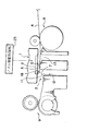
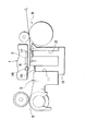
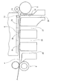
以下、本願発明の実施の形態を図面に基づいて説明する。図1は本発明に係る第1の実施の形態のインクジェット記録装置を示し、記録用紙の始端を余白無く記録している状態の要部断面図であり、図2は第1の実施の形態の記録用紙終端を余白無く記録している状態の要部断面図である。 Hereinafter, embodiments of the present invention will be described with reference to the drawings. FIG. 1 shows an ink jet recording apparatus according to a first embodiment of the present invention. FIG. 1 is a cross-sectional view of a main part in a state in which the start end of a recording sheet is recorded without margins, and FIG. 2 shows the first embodiment. FIG. 6 is a cross-sectional view of a main part in a state where the end of the recording paper is recorded without margins.
本実施の形態では、図1に示したように、プラテン3は、ノズルアレイ2の副走査方向の下流側部分と対向する部分のプラテン面に第1穴11が設けられている。この第1穴11は、記録用紙4の始端7を余白無く記録する際に、該始端7から外れて打ち捨てられたインク12を当該第1穴11で総て受ける役割を果たすもので、その役割が果たせるように紙幅方向に一連で長尺(後述する図5および図6参照)に、或いは、部分的に仕切られて設けられている。
In the present embodiment, as shown in FIG. 1, the
すなわち、本実施の形態では、第1穴11がプラテン面の全体ではなく、記録用紙4の始端7を余白無く記録する際における当該始端7に対応する位置に局在して形成されている。プラテン面の記録ヘッド1と対向する部位には記録用紙1の記録時の位置を規定するための位置規定機能部が残されている。すなわち、ノズルアレイ2と対向する範囲内にリブ5およびその平坦な頂面6が位置するように形成されている。従って、記録用紙4の始端7を余白無く記録する際に、該始端7から外れて打ち捨てられたインク12は第1穴11に導かれ、それでいて記録用紙4はリブ5の平坦な頂面6にしっかりと位置規定される。これにより、記録ヘッド1に対する記録用紙4の位置を安定させてしっかりと規定することができる。
That is, in the present embodiment, the first hole 11 is formed not locally on the entire platen surface but locally at a position corresponding to the
更に、本実施の形態では、ノズルアレイ2の副走査方向の上流側部分と対向する部分のプラテン面に第2穴13が設けられている。この第2穴13は、図2に示したように、記録用紙4の終端14を余白無く記録する際に該終端14から外れて打ち捨てられたインク12を該第2穴13に導くように形成されており、前記第1穴11と役割は共通する。図において、符号8は紙送りローラ、符号9は排紙ローラであり、いずれも公知のものである。
Furthermore, in the present embodiment, the
なお、上記実施の形態では、第1穴11および第2穴13の両方を備えたプラテンを示したが、いずれか一方の穴だけを設けたものでもよく、その区分けは想定される記録の仕方に基づいて決められる。
In the above embodiment, the platen provided with both the first hole 11 and the
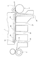
更に、前記ノズルアレイ2と対向する範囲内に前記リブ5の平坦な頂面6が位置しているものを示したが、図3および図4に示した如く、前記ノズルアレイ2と対向する範囲外の下流側に当該平坦な頂面6が位置している構造にしてもよい。この構造を採用すれは、全ノズルを使用しての記録中に誤って、前記ノズルアレイ2と対向する位置のプラテン面にインクが付着しても、記録中の記録用紙4が排出されるまで、該用紙4が汚れることはない。また、被記録材送りローラ8から前記平坦な頂面6までの距離を遠く設定できるので、記録用紙4の搬送負荷を軽くでき、特に厚い用紙の搬送性を向上できる。
Further, the flat
本実施の形態では、記録ヘッド1のノズルアレイ2を駆動するノズル駆動制御部23(図1にのみ示し、他の図では省略した)が、米国特許第5,844,585号明細書等に開示されている「インターレース記録」と、更に、特開平9−71009号公報や特開平11−291506号公報に開示されている、記録用紙の始端または終端の余白をできるだけ小さくする為に、全ノズルの内の一部だけを限定駆動して記録する「限定インターレース記録」とを切り換えて実行するように構成されている。すなわち、図1、図3及び図5に示したように、ノズルアレイ2の排紙方向側の一部18だけがノズル駆動制御部23によって駆動されて、記録用紙4の始端7側だけにインクが噴射されるようになっている。同様に記録用紙4の終端14側についても図2、図4及び図6に示したようにノズルアレイ2の一部19だけが駆動されるようになっている。
In this embodiment, a nozzle drive control unit 23 (shown only in FIG. 1 and omitted in other drawings) for driving the
ここで、図29に基づいて、前記記録ヘッド1は、前記ドット形成要素アレイを駆動するドット駆動制御部23によって、ドット形成要素アレイ2の全ドット形成要素を駆動させて記録する標準インターレース記録と、一部のドット形成要素に限定して駆動させて記録する限定インターレース記録とを切り換えて実行可能に構成されており、記録用紙4の始端7が前記第1穴11部分に位置するとき、及び記録用紙4の終端14が前記第2穴13部分に位置するときに、前記限定インターレース記録が実行されるように構成されていること説明する。
Here, based on FIG. 29, the
図29は、各主走査時のノズルの副走査方向の位置を表した図である。図29の上下方向が副走査方向に相当する。図の頬雑さを避けるため、ノズル位置を主走査ごとに順次右にずらして示した。解りやすくするためにノズルアレイ2とインク打ち捨て用にプラテンに設けられる穴を併記した。図29において、P1,P2…は1回目、2回目…の主走査を意味している。丸囲みの数字は、各走査におけるノズルの副走査方向の位置を示している。また、太線で丸囲みしてある数字は、その位置でドットが形成されることを意味しており、細い線で丸囲みしてある数字はノズルが位置するものの、ドットは形成されないことを意味している。図29の左側に示した値は各ラスタに便宜上付したラスタ番号RNであり、後述する通り、この記録方法によって副走査における紙送り精度を保証しつつ画像が記録される最も下方のラスタをラスタ番号0(RN=0)とし、それよりも下方のラスタを正の数字で、上方のラスタを負の数字で表している。「L=」の形で表した数字は、各副走査における紙送り量をラスタ数で表したものである。
FIG. 29 is a diagram showing the position of the nozzle in the sub-scanning direction during each main scanning. The vertical direction in FIG. 29 corresponds to the sub-scanning direction. In order to avoid cheekness in the figure, the nozzle positions are sequentially shifted to the right for each main scan. In order to facilitate understanding, the
標準印刷処理ルーチンが開始されると、ドット形成データを設定され、主走査を行いつつドットを形成する。図29の例では、ノズルピッチは4ラスタ分であるから、ドット形成用のデータは、先に入力した画像データの先頭から4ラスタおきに主走査方向に順にデータを抽出したものとなる。図29中の主走査P1では、ラスター番号−28より上方の領域(RN≦−28なる領域)で、4ラスタおきにドットが形成される。 When the standard print processing routine is started, dot formation data is set, and dots are formed while performing main scanning. In the example of FIG. 29, since the nozzle pitch is for four rasters, the data for dot formation is obtained by sequentially extracting data in the main scanning direction every four rasters from the head of the previously input image data. In the main scan P1 in FIG. 29, dots are formed every four rasters in the region above the raster number -28 (region where RN≤-28).
次に、紙送りローラ8が駆動制御されて、副走査が行われる。図29の例では、7ラスタに相当する紙送りが実行され、記録ヘッド1の位置は図29中のP2まで移動する。この送り量は、インターレース方式によりラスタの抜けが生じることなく画像を記録することができる種々の送り量のうち、ノズルを最も有効に用いることができる送り量に設定してある。送り量はノズルピッチ、ノズル個数およびスキャン繰り返し数に応じて定めることができるが、その設定方法は周知であるため説明を省略する。
Next, the
副走査を行った後、主走査P2で示した位置、即ちラスタ番号−20より上方の領域にドットを形成する。この処理の繰り返しにより、ラスタを間欠的に形成しつつ、画像を記録することができる、例えば、図29から明らかな通り、主走査P4までが実行されると、ラスタ番号−34から−25の領域では画像が完成していることが分かる。以下、画像の形成が終了するまで、この処理を繰り返し実行して、画像を形成する。但し、本実施例では、後述する通り、標準印刷処理の後に、別の印刷モードによる印刷を実行するため、ここでいう画像の形成が終了とは、入力された画像データ全体の印刷の終了ではなく、標準印刷処理ルーチンによる画像の形成の終了を意味している。 After the sub-scanning, dots are formed at the position indicated by the main scanning P2, that is, the region above the raster number -20. By repeating this process, it is possible to record an image while intermittently forming a raster. For example, as shown in FIG. 29, when the main scan P4 is executed, raster numbers −34 to −25 are recorded. It can be seen that the image is completed in the area. Thereafter, this process is repeatedly executed until the image formation is completed to form an image. However, in this embodiment, as will be described later, printing in another printing mode is executed after the standard printing process. Therefore, the end of the image formation referred to here is the end of printing of the entire input image data. In other words, it means the end of image formation by the standard print processing routine.
標準印刷処理による画像の形成が終了した後、中間処理による画像の印刷が実行される。中間処理におけるドット形成の流れ自体は、標準印刷処理ルーチンと同様である。中間処理では、副走査における紙送り量が標準印刷における紙送り量と相違する。 After the image formation by the standard printing process is completed, the image printing by the intermediate process is executed. The flow of dot formation in the intermediate process is the same as that in the standard printing process routine. In the intermediate processing, the paper feed amount in the sub-scan is different from the paper feed amount in the standard printing.
中間処理においては、標準処理における7ラスタ相当の紙送り量とは異なり、まず4ラスタ相当の紙送りを実行し、ラスタを形成する(図29の主走査P5)。この4ラスタの意味については後述する。次に、3ラスタの紙送りを行いつつ、ラスタを形成する(図29の主走査P6〜P8)。この際、例えば主走査P7における1番ノズルのように、既に形成されたラスタ位置にノズルが重複して存在する場合もあるため、かかるノズルはドットの形成データをマスクし、ドットの形成が行われないようにされる。なお、図29の主走査P8の位置が、精度を保証しつつ紙送りをすることができる限界位置である。つまり、このとき用紙4の下端は、紙送りローラ8から外れる直前の状態にあることになる。
In the intermediate process, unlike the paper feed amount equivalent to 7 rasters in the standard process, first, paper feed equivalent to 4 rasters is executed to form a raster (main scan P5 in FIG. 29). The meaning of these four rasters will be described later. Next, a raster is formed while feeding paper of three rasters (main scans P6 to P8 in FIG. 29). At this time, for example, the first nozzle in the main scan P7 may have overlapping nozzles at the already formed raster position, so such nozzles mask the dot formation data and perform dot formation. You will be kept from breaking. Note that the position of the main scan P8 in FIG. 29 is a limit position where the paper can be fed while guaranteeing accuracy. That is, at this time, the lower end of the
中間処理における送り量の設定について説明する。本実施例の中間処理においては、4ラスタの過渡的な送り量に続いて3ラスタの一定の送り量による紙送りが行われている。この一定の送り量は、4ラスタ分のノズルピッチからなる3つのノズルが備えられている場合のインターレース方式の送り量に相当する。また、中間処理の最初に実行した4ラスタ分の過渡的な送りも、ラスタの抜けが生じないように設定されるものである。過渡的な送り量は、標準処理における送り量等のパラメータと中間処理における送り量等のパラメータ双方に基づいて定まるものである。 The setting of the feed amount in the intermediate process will be described. In the intermediate processing of this embodiment, paper feed is performed with a constant feed amount of 3 rasters following a transient feed amount of 4 rasters. This constant feed amount corresponds to an interlace feed amount when three nozzles having a nozzle pitch of four rasters are provided. In addition, the transitional feed for four rasters executed at the beginning of the intermediate process is also set so as not to cause a missing raster. The transient feed amount is determined based on both a parameter such as a feed amount in standard processing and a parameter such as a feed amount in intermediate processing.
このように中間処理において使用ノズル数を見かけ上減らしたインターレース記録を実行するのは、かかる記録方式を採用することにより、紙送り精度を保証した状態で画像を記録することができる領域を拡張することができるからである。 In this way, the interlaced recording in which the number of used nozzles is apparently reduced in the intermediate processing is executed by using such a recording method, thereby extending the area where the image can be recorded with the paper feeding accuracy guaranteed. Because it can.
拡張印刷領域では各3ラスタの送りによる副走査を行いつつ、ドットを記録している。このように設定したとき、インターレース方式による記録をするための送り量はさらに減少し、3ラスタ分となる。 In the extended print area, dots are recorded while performing sub-scanning by sending three rasters. When set in this way, the feed amount for recording by the interlace method is further reduced to 3 rasters.
このように設定した後、使用ノズルの設定が行われ、使用しないノズルについてはデータマスク処理を行う。データマスク処理とはドットが形成されないようにする処理をいう。 After such setting, the used nozzles are set, and data mask processing is performed for the nozzles that are not used. Data mask processing refers to processing that prevents dots from being formed.
次に、拡張印刷処理が実行される。中間処理では、副走査における紙送り量が標準印刷における紙送り量と相違する。先に説明した通り、拡張印刷処理においては、3ラスタ分の送り量によるインターレース方式でドットを形成する。このとき、ラスタ番号0よりも上方の領域(RN≦0なる領域)では既に画像が形成されているため、かかる領域に存在するノズルはドットを形成しない。 Next, extended printing processing is executed. In the intermediate processing, the paper feed amount in the sub-scan is different from the paper feed amount in the standard printing. As described above, in the extended printing process, dots are formed by an interlace method using a feed amount for three rasters. At this time, since an image has already been formed in the region above the raster number 0 (region where RN ≦ 0), the nozzles existing in the region do not form dots.
以上で説明したように、標準印刷を行う領域においては、インターレース方式により高画質な画像を得ることができる。また、中間処理を採用することにより、紙送りの精度を保証しつつ画像を形成することができる領域を拡張することができる。このように拡張された領域においてもインターレース方式による画像の記録が行われているため、高画質な画像を得ることができる。画像を記録することができる領域は、されに拡張印刷を実行することにより下方に拡張することができる。 As described above, in the area where standard printing is performed, a high-quality image can be obtained by the interlace method. In addition, by adopting the intermediate processing, it is possible to expand an area where an image can be formed while guaranteeing accuracy of paper feeding. Since an image is recorded by the interlace method even in such an extended area, a high-quality image can be obtained. An area in which an image can be recorded can be expanded downward by executing extended printing.
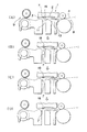
図29に基づいて説明した全ノズル駆動の標準インターレース記録および使用ノズルを限定した拡張処理即ち限定インターレース記録は、特開平11−291506号公報に記載されている公知の手法である。標準インターレース記録と限定インターレース記録の実行により、記録用紙4の始端7に余白なし記録を行う工程を図11(A)乃至図11(D)に示した。第1穴11に用紙の始端7が至ってから、この始端部分についてはノズルアレイ2の一部18を用い、この一部18部分の各ノズルを用いて、図29で説明した手法によって、拡張印刷処理を実行し、各図に示したように少しのインクを第1穴11に打ち捨てつつ、始端余白なしの記録が行われる。
The standard interlace recording for all-nozzle driving and the extension processing for limiting the nozzles used, that is, the limited interlace recording described with reference to FIG. 29, are known methods described in Japanese Patent Laid-Open No. 11-291506. 11A to 11D show a process of performing marginless recording on the starting
標準インターレース記録と限定インターレース記録の実行により、記録用紙4の終端14に余白なし記録を行う工程を図12(A)乃至図12(D)に示した。基本的に始端7の余白なし記録と同様なので説明は省略する。
FIGS. 12A to 12D show a process for performing marginless recording on the
以上、余白無し記録を、限定インターレース記録により実行する例を説明したが、このように記録用紙4の始端7や終端14を余白無く記録するときは、限定インターレース記録を実行することで、図1に例で言うと第1の穴11と第2の穴13に打ち捨てられるインク12の量を減らせると共に、この始端7や終端14部分におけるコックリングの程度を小さくすることができる。そして、記録用紙4の始端7や終端14以外の部分は、通常のインターレース記録を実行することで、スループットを低下することなく、高画質の記録を維持して記録を実行することができる。
As described above, the example in which the marginless recording is performed by the limited interlace recording has been described. However, when the
図1および図2に示した実施の形態によれば、記録用紙4の始端7及び終端14を余白無く記録する際に、該始端7及び終端14から外れて打ち捨てられたインク12は第1穴11及び第2穴13にそれぞれ導かれ、その際、記録用紙4はリブ5の平坦な頂面6によってしっかりと記録ヘッド1に対する位置が規定される。従って、記録用紙4の始端7及び終端13を余白無く記録する場合に、記録用紙4が打ち捨てられたインク12の再付着によって汚損される虞がなく、更に記録用紙4の記録持の位置がしっかりと規定され、高い記録品質を維持して記録することができる。
According to the embodiment shown in FIGS. 1 and 2, when recording the
図7は、本発明に係るインクジェット記録装置の他の実施の形態を示し、図1の実施の形態にインク吸収体が付加されたものである。すなわち、前記第1の穴11および第2穴13内の底部にインク吸収体15が設けられている。インク吸収体15としては、例えば合成樹脂製の連続発泡体や不織布等の繊維質の集合体が挙げられる。このインク吸収体15により、打ち捨てられたインク12を漏洩させずに安定して貯溜しておくことができ、また、その取り出し交換作業も容易に行える。
FIG. 7 shows another embodiment of the ink jet recording apparatus according to the present invention, in which an ink absorber is added to the embodiment of FIG. That is, an
また、図8は更に本願発明の他の実施の形態を示すもので、前記第1穴11および第2穴13の開口部に撥水性の網体16,17がそれぞれ被設されている。そして、この網体16,17と接触するようにしてインク吸収体15が第1穴11および第2穴13内に設けられている。本実施の形態によれば、前記網体16,17により第1穴11および第2穴13の開口部が覆われているため、記録用紙4の搬送に際しては、当該穴11,13が無いのとほとんど同様の状態になり、記録用紙4をしっかりと位置規定することができる。更に、打ち捨てられたインク12が該網体16,17に当たって付着するが、それが撥水性であるため、付着したインクは直ぐにインク吸収体15に吸収され、記録用紙4との接触面には、付着インクが殆ど存在しないようになる。従って、記録用紙4の位置をしっかりと規定しつつ、前記打ち捨てインク再付着の虞をほとんど無くすことができる。
FIG. 8 shows still another embodiment of the present invention. Water-
図9及び図10は、更に本願発明の他の実施の形態を示し、前記第1穴11及び第2穴13の開口部に開閉可能な蓋体20,21が設けられている。この蓋体20,21は、記録用紙4の始端7(図9)または終端(図10)を余白無く記録する際に開蓋され、前記余白無し記録以外の記録のときは閉じられている。個の開閉駆動は図示しない制御部によって行われる。更に本実施の形態では、蓋体20,21は、前記第1穴11および第2穴13の開口部より下方に回動支点22を有し、該回動支点22を中心に回動して図示しない駆動制御部によって開閉駆動されるようになっている。
FIGS. 9 and 10 show still another embodiment of the present invention, and
本実施の形態によれば、プラテン面の第1穴11および第2穴13は、蓋体20,21により、記録用紙4の始端7または終端14を余白無く記録する際に開かれ、前記余白無し記録以外のときは閉じられるので、機能的に無駄がない。更に、回動支点22を前記穴20,21の開口部より下方に位置させたので、記録用紙4の搬送経路上に当該蓋体20,21を開閉させる機構を存在させなくすることができる、従って、新たな部材を設けることによって紙ジャム発生の虞が増すことを防止できる。
According to the present embodiment, the first hole 11 and the
次に、図13は、中央穴25を有する実施の形態に係るインクジェット式記録装置で記録用紙の始端に記録をしている状態の概略の要部断面図であり、図14は、図13のインクジェット式記録装置で記録用紙の始端に記録をしている状態の要部平面図である。前記プラテン3は、前記ドット形成要素アレイ2と対向する部分のプラテン面に前記記録用紙4をその下から接触して支える平坦な頂面6が設けられ、該頂面6の記録用紙4の搬送方向におけるほぼ中央部に中央穴25が設けられている。該中央穴25と対向する部位のノズルアレイ2の一部24が余白無し記録に用いられる。記録用紙4の始端7及び/又は終端14を余白無く記録する際に該始端7又は終端14から外れて打ち捨てられたインク12を該中央穴25に導くように形成されている。
Next, FIG. 13 is a schematic cross-sectional view of the main part in a state where recording is performed at the start end of the recording paper in the ink jet recording apparatus according to the embodiment having the
本構成により、前記平坦な頂面6により、記録用紙4を安定良く支えつつ、前記中央穴25を1つで記録用紙4の始端7及び/又は終端14に余白無し記録を実行することができる。
With this configuration, the flat
図15は、中央穴25を有する実施の形態に係るインクジェット式記録装置で記録用紙4の終端14に記録をしている状態の概略の要部断面図であり、図16は、図15のインクジェット式記録装置で記録用紙4の終端14に記録をしている状態の要部平面図である。図13及び図14と基本的に同様なので図面に符号を付して説明は省略する。
FIG. 15 is a schematic cross-sectional view of the main part in a state where recording is performed on the
次に、図17は、3色に対応する3つのドット形成要素アレイ2a,2b,2cが副走査方向に並んだ実施の形態に係るインクジェット式記録装置で、記録用紙4の始端7に記録をしている状態の概略の要部断面図である。また、図18は、図17の状態のインクジェット式記録装置で記録用紙4の始端7に記録をしている状態の要部平面図である。この記録ヘッド1は、副走査方向に複数のドット形成要素が配列された3色用のドット形成要素アレイ2a,2b,2cを有すると共に、各色に対応する3つのドット形成要素アレイ2a,2b,2cが副走査方向に順次配列されて成る。この図の状態は、最も上流側に位置するドット形成要素アレイ2aの一部30によって記録用紙4の始端7に余白をなしにする限定インターレース記録が行われている。
Next, FIG. 17 shows an ink jet recording apparatus according to an embodiment in which three dot forming
前記プラテン3は、1つの色に対応する前記ドット形成要素アレイ2aに対して、副走査方向の下流側部分と対向する部分のプラテン面に第1穴27が設けられると共に、副走査方向の上流側部分と対向する部分のプラテン面に第2穴26が設けられている。他の色に対応する前記ドット形成要素アレイ2bに対して、副走査方向の下流側部分と対向する部分のプラテン面に第1穴28が設けられると共に、副走査方向の上流側部分と対向する部分のプラテン面に第2穴27が設けられている。更に、他の色に対応する前記ドット形成要素アレイ2cに対して、副走査方向の下流側部分と対向する部分のプラテン面に第1穴29が設けられると共に、副走査方向の上流側部分と対向する部分のプラテン面に第2穴28が設けられている。前記の如く、ドット形成要素アレイ2aの第1穴27は、そのまま前記ドット形成要素アレイ2bの第2穴27となっている。同様にドット形成要素アレイ2bの第1穴28は、そのまま前記ドット形成要素アレイ2cの第2穴28となっている。
The
そして、各色に対応する前記複数の各ドット形成要素アレイ2a,2b,2cのそれぞれに対して、被記録用紙4の始端7を余白無く記録する際に該始端7から外れて打ち捨てられたインクを前記第1穴27に導き、被記録材の終端14を余白無く記録する際に該終端14から外れて打ち捨てられたインクを前記第2穴26に導くように形成されている。
Then, when the
本構成によれば、複数のカラーノズルを縦配列して並べたような場合でも、各カラーの各ドット形成要素アレイ毎に前記第1穴27,28,29及び第2穴26,27,28が設けられているので、カラーノズルを横配列した記録ヘッドと変わらずに、被記録材の始端7及び終端14について、余白無し記録を実行することができる。
According to this configuration, even when a plurality of color nozzles are arranged vertically, the
図19は、インクジェット式記録装置の中部に位置するドット形成要素アレイ2bで記録用紙4の始端7に記録をしている状態の概略の要部断面図であり、図20は、図19の状態のインクジェット式記録装置で記録用紙4の始端7に記録をしている状態の要部平面図である。
FIG. 19 is a schematic cross-sectional view of the main part of a state in which recording is performed on the
図21は、インクジェット式記録装置の下流側のドット形成要素アレイ2cで記録用紙4の始端7に記録をしている状態の概略の要部断面図であり、図22は、図21の状態のインクジェット式記録装置で記録用紙4の始端7に記録をしている状態の要部平面図である。
FIG. 21 is a schematic cross-sectional view of the main part in a state where the dot forming
以上により、カラー3色の総てに対して、簡単に余白無し記録を実行する事ができる。 As described above, marginless recording can be easily executed for all three colors.
図23は、上流側のドット形成要素アレイ2aで記録用紙4の終端14に記録をしている状態の概略の要部断面図である。図24は、図23の状態のインクジェット式記録装置で記録用紙4の終端14に記録をしている状態の要部平面図である。ここでは、第2穴26がインクの打ち捨てに利用される。
FIG. 23 is a schematic cross-sectional view of the main part in a state where recording is performed on the
図25は、インクジェット式記録装置の中部に位置するドット形成要素アレイ2bで記録用紙4の終端14に記録をしている状態の概略の要部断面図であり、図26は、図25の状態のインクジェット式記録装置で記録用紙4の終端14に記録をしている状態の要部平面図である。ここでは、第2穴27がインクの打ち捨てに利用される。
FIG. 25 is a schematic cross-sectional view of the main part in a state where recording is performed on the
図27は、インクジェット式記録装置の下流側のドット形成要素アレイ2cで記録用紙4の終端14に記録をしている状態の概略の要部断面図である。図28は、図27の状態のインクジェット式記録装置で記録用紙4の終端14に記録をしている状態の要部平面図である。ここでは、第2穴28がインクの打ち捨てに利用される。
FIG. 27 is a schematic cross-sectional view of a main part in a state where recording is performed on the
本発明によれば、被記録材の始端や終端に余白無く記録する際に、該始端や終端から外れて打ち捨てられたインクは第1穴と第2穴それぞれに導かれ、それでいて被記録材は位置規定機能部によりしっかりと記録ヘッドに対する位置が規定される。従って、被記録材の始端や終端に余白無く記録する場合に、被記録材が打ち捨てられたインクで汚損される虞がなく、更に被記録材の記録持の位置がしっかりと規定され記録品質を低下させない。 According to the present invention, when recording without a margin at the start and end of the recording material, the ink that has been removed from the start and end is led to the first hole and the second hole, respectively. The position relative to the recording head is firmly defined by the position defining function unit. Therefore, when recording without a margin at the beginning or end of the recording material, there is no risk of the recording material being damaged by the discarded ink, and the recording holding position of the recording material is firmly defined and the recording quality is improved. Do not decrease.
1 記録ヘッド、2 ノズルアレイ、3 プラテン、4 記録用紙、5 リブ、
6 頂部、7 記録用紙の始端、11 第1穴、12 打ち捨てられたインク、
13 第2穴、14 記録用紙の終端、15 インク吸収体、16,17 網体、
18,19 ノズルアレイの一部、20,21 蓋体、22 回動支点
1 recording head, 2 nozzle array, 3 platen, 4 recording paper, 5 rib,
6 Top, 7 Start edge of recording paper, 11 1st hole, 12 Abandoned ink,
13 Second hole, 14 End of recording paper, 15 Ink absorber, 16, 17 Mesh,
18,19 Part of nozzle array, 20,21 Lid, 22 Rotating fulcrum
Claims (1)
該記録ヘッドの上流側に配設された被記録材送りローラと、前記記録ヘッドの下流側に配設された排出ローラと、
被記録材を支えることが可能なリブと、を備え、
被記録材の始端を余白なく記録する際は、被記録材の搬送方向において前記リブに対して下流側で被記録材の始端をはみ出してインクが打ち捨てられるように記録し、
被記録材の終端を余白なく記録する際は、被記録材の搬送方向において前記リブに対して上流側で被記録材の終端をはみ出してインクが打ち捨てられるように記録し、
前記リブは、前記被記録材の搬送方向下流側に向って徐々に高くなる部位を有し、被記録材の始端及び終端を余白なく記録する際に前記打ち捨てられたインクが付着しない位置で被記録材を支える構成である
ことを特徴とするインクジェット記録装置。 A recording head having a dot forming element array in which a plurality of dot forming elements are arranged in the sub-scanning direction;
A recording material feed roller disposed on the upstream side of the recording head; a discharge roller disposed on the downstream side of the recording head;
A rib capable of supporting a recording material,
When recording the start end of the recording material without margins, recording is performed such that the start end of the recording material protrudes on the downstream side of the rib in the conveyance direction of the recording material and the ink is discarded.
When recording the end of the recording material without margin, recording is performed so that the end of the recording material protrudes on the upstream side of the rib in the conveyance direction of the recording material and the ink is discarded.
The rib has a portion that gradually increases toward the downstream side in the conveyance direction of the recording material , and the ribbed ink is not attached to the recording material when the start and end of the recording material are recorded without margins. An ink jet recording apparatus having a structure for supporting a recording material.
Priority Applications (1)
| Application Number | Priority Date | Filing Date | Title |
|---|---|---|---|
| JP2009298299A JP4650645B2 (en) | 1999-04-06 | 2009-12-28 | Inkjet recording device |
Applications Claiming Priority (3)
| Application Number | Priority Date | Filing Date | Title |
|---|---|---|---|
| JP9838399 | 1999-04-06 | ||
| JP9838099 | 1999-04-06 | ||
| JP2009298299A JP4650645B2 (en) | 1999-04-06 | 2009-12-28 | Inkjet recording device |
Related Parent Applications (1)
| Application Number | Title | Priority Date | Filing Date |
|---|---|---|---|
| JP2006313639A Division JP2007038691A (en) | 1999-04-06 | 2006-11-20 | Ink-jet recording apparatus and recording method therefor |
Related Child Applications (3)
| Application Number | Title | Priority Date | Filing Date |
|---|---|---|---|
| JP2010152858A Division JP4716062B2 (en) | 1999-04-06 | 2010-07-05 | Inkjet recording device |
| JP2010152859A Division JP4775604B2 (en) | 1999-04-06 | 2010-07-05 | Inkjet recording device |
| JP2010213296A Division JP5212662B2 (en) | 1999-04-06 | 2010-09-24 | Inkjet recording device |
Publications (2)
| Publication Number | Publication Date |
|---|---|
| JP2010069887A JP2010069887A (en) | 2010-04-02 |
| JP4650645B2 true JP4650645B2 (en) | 2011-03-16 |
Family
ID=42202089
Family Applications (6)
| Application Number | Title | Priority Date | Filing Date |
|---|---|---|---|
| JP2009298299A Expired - Fee Related JP4650645B2 (en) | 1999-04-06 | 2009-12-28 | Inkjet recording device |
| JP2010152859A Expired - Fee Related JP4775604B2 (en) | 1999-04-06 | 2010-07-05 | Inkjet recording device |
| JP2010152858A Expired - Lifetime JP4716062B2 (en) | 1999-04-06 | 2010-07-05 | Inkjet recording device |
| JP2010213296A Expired - Fee Related JP5212662B2 (en) | 1999-04-06 | 2010-09-24 | Inkjet recording device |
| JP2011028585A Expired - Fee Related JP5177243B2 (en) | 1999-04-06 | 2011-02-14 | Inkjet recording device |
| JP2011092776A Expired - Fee Related JP5136811B2 (en) | 1999-04-06 | 2011-04-19 | Inkjet recording device |
Family Applications After (5)
| Application Number | Title | Priority Date | Filing Date |
|---|---|---|---|
| JP2010152859A Expired - Fee Related JP4775604B2 (en) | 1999-04-06 | 2010-07-05 | Inkjet recording device |
| JP2010152858A Expired - Lifetime JP4716062B2 (en) | 1999-04-06 | 2010-07-05 | Inkjet recording device |
| JP2010213296A Expired - Fee Related JP5212662B2 (en) | 1999-04-06 | 2010-09-24 | Inkjet recording device |
| JP2011028585A Expired - Fee Related JP5177243B2 (en) | 1999-04-06 | 2011-02-14 | Inkjet recording device |
| JP2011092776A Expired - Fee Related JP5136811B2 (en) | 1999-04-06 | 2011-04-19 | Inkjet recording device |
Country Status (1)
| Country | Link |
|---|---|
| JP (6) | JP4650645B2 (en) |
Families Citing this family (2)
| Publication number | Priority date | Publication date | Assignee | Title |
|---|---|---|---|---|
| CN202412940U (en) | 2010-11-30 | 2012-09-05 | 兄弟工业株式会社 | Pressing plate and image recording device |
| JP5621556B2 (en) * | 2010-11-30 | 2014-11-12 | ブラザー工業株式会社 | Platen and image recording apparatus |
Citations (6)
| Publication number | Priority date | Publication date | Assignee | Title |
|---|---|---|---|---|
| JPH079712A (en) * | 1993-06-15 | 1995-01-13 | Canon Inc | Ink jet recording apparatus |
| JPH08169155A (en) * | 1994-10-21 | 1996-07-02 | Seiko Epson Corp | Ink-jet printer as well as recording medium and recording medium supply source for the printer |
| JPH08309966A (en) * | 1995-05-24 | 1996-11-26 | Seiko Epson Corp | Ink jet printer |
| JPH10128964A (en) * | 1996-10-31 | 1998-05-19 | Canon Inc | Ink jet recording device |
| JP2000118058A (en) * | 1998-10-20 | 2000-04-25 | Hewlett Packard Co <Hp> | Apparatus and method for printing print image |
| JP2000127372A (en) * | 1998-10-28 | 2000-05-09 | Casio Comput Co Ltd | Carriage moving type printing apparatus |
Family Cites Families (6)
| Publication number | Priority date | Publication date | Assignee | Title |
|---|---|---|---|---|
| JPS63299940A (en) * | 1987-05-30 | 1988-12-07 | Canon Inc | Ink jet recording apparatus |
| JP3437319B2 (en) * | 1994-04-05 | 2003-08-18 | キヤノン株式会社 | Ink jet recording apparatus and ink jet image forming method |
| US5820283A (en) * | 1996-12-17 | 1998-10-13 | Hewlett-Packard Company | Print media handling system including dual incline support for controlling pen to paper spacing |
| JPH10226059A (en) * | 1997-02-18 | 1998-08-25 | Canon Inc | Printer |
| JPH10315444A (en) * | 1997-05-19 | 1998-12-02 | Seiko Epson Corp | Recording method and recording medium used for the method |
| JP3887985B2 (en) * | 1999-02-25 | 2007-02-28 | カシオ計算機株式会社 | Inkjet printer |
-
2009
- 2009-12-28 JP JP2009298299A patent/JP4650645B2/en not_active Expired - Fee Related
-
2010
- 2010-07-05 JP JP2010152859A patent/JP4775604B2/en not_active Expired - Fee Related
- 2010-07-05 JP JP2010152858A patent/JP4716062B2/en not_active Expired - Lifetime
- 2010-09-24 JP JP2010213296A patent/JP5212662B2/en not_active Expired - Fee Related
-
2011
- 2011-02-14 JP JP2011028585A patent/JP5177243B2/en not_active Expired - Fee Related
- 2011-04-19 JP JP2011092776A patent/JP5136811B2/en not_active Expired - Fee Related
Patent Citations (6)
| Publication number | Priority date | Publication date | Assignee | Title |
|---|---|---|---|---|
| JPH079712A (en) * | 1993-06-15 | 1995-01-13 | Canon Inc | Ink jet recording apparatus |
| JPH08169155A (en) * | 1994-10-21 | 1996-07-02 | Seiko Epson Corp | Ink-jet printer as well as recording medium and recording medium supply source for the printer |
| JPH08309966A (en) * | 1995-05-24 | 1996-11-26 | Seiko Epson Corp | Ink jet printer |
| JPH10128964A (en) * | 1996-10-31 | 1998-05-19 | Canon Inc | Ink jet recording device |
| JP2000118058A (en) * | 1998-10-20 | 2000-04-25 | Hewlett Packard Co <Hp> | Apparatus and method for printing print image |
| JP2000127372A (en) * | 1998-10-28 | 2000-05-09 | Casio Comput Co Ltd | Carriage moving type printing apparatus |
Also Published As
| Publication number | Publication date |
|---|---|
| JP2011102043A (en) | 2011-05-26 |
| JP5177243B2 (en) | 2013-04-03 |
| JP2010228459A (en) | 2010-10-14 |
| JP2010280230A (en) | 2010-12-16 |
| JP2010228460A (en) | 2010-10-14 |
| JP2010069887A (en) | 2010-04-02 |
| JP2011140239A (en) | 2011-07-21 |
| JP4775604B2 (en) | 2011-09-21 |
| JP5136811B2 (en) | 2013-02-06 |
| JP4716062B2 (en) | 2011-07-06 |
| JP5212662B2 (en) | 2013-06-19 |
Similar Documents
| Publication | Publication Date | Title |
|---|---|---|
| JP3904055B2 (en) | Inkjet recording device | |
| US20040021734A1 (en) | Printing by switching sub-scan feeding between monochromatic and color areas | |
| JP4650645B2 (en) | Inkjet recording device | |
| JP3904090B2 (en) | Inkjet recording device | |
| JP4463118B2 (en) | Ink jet recording apparatus and recording method using the recording apparatus | |
| JP3674042B2 (en) | Inkjet recording device | |
| JP3904088B2 (en) | Inkjet recording device | |
| JP2007118608A (en) | Inkjet recording device and recording method by this recording device | |
| EP2574466B1 (en) | Inkjet printer and image recording method | |
| JP2007038691A (en) | Ink-jet recording apparatus and recording method therefor | |
| JP2008120102A (en) | Inkjet recording device | |
| US6869176B2 (en) | Recording apparatus, and recording medium floating prevention member | |
| JP7230532B2 (en) | Liquid ejector | |
| JP4194226B2 (en) | Ink jet recording apparatus and image data correction method | |
| JP4114014B2 (en) | Image forming apparatus | |
| JP2005178000A (en) | Inkjet recording apparatus and inkjet recording method | |
| JP6885006B2 (en) | Printing equipment | |
| JP2006159547A (en) | Inkjet recorder | |
| JP2024005460A (en) | Liquid discharge apparatus | |
| JP3826088B2 (en) | Recording device | |
| JP2023019994A (en) | Inkjet recording device | |
| JP2004230863A (en) | Ink jet recording apparatus | |
| JP2023151803A (en) | Ink jet recording device | |
| JPH09141894A (en) | Ink jet recorder | |
| JP2022138554A (en) | Inkjet recording device |
Legal Events
| Date | Code | Title | Description |
|---|---|---|---|
| A621 | Written request for application examination |
Free format text: JAPANESE INTERMEDIATE CODE: A621 Effective date: 20100126 |
|
| A131 | Notification of reasons for refusal |
Free format text: JAPANESE INTERMEDIATE CODE: A131 Effective date: 20100506 |
|
| A521 | Written amendment |
Free format text: JAPANESE INTERMEDIATE CODE: A523 Effective date: 20100705 |
|
| A131 | Notification of reasons for refusal |
Free format text: JAPANESE INTERMEDIATE CODE: A132 Effective date: 20100728 |
|
| A521 | Written amendment |
Free format text: JAPANESE INTERMEDIATE CODE: A523 Effective date: 20100924 |
|
| TRDD | Decision of grant or rejection written | ||
| A01 | Written decision to grant a patent or to grant a registration (utility model) |
Free format text: JAPANESE INTERMEDIATE CODE: A01 Effective date: 20101117 |
|
| A01 | Written decision to grant a patent or to grant a registration (utility model) |
Free format text: JAPANESE INTERMEDIATE CODE: A01 |
|
| A61 | First payment of annual fees (during grant procedure) |
Free format text: JAPANESE INTERMEDIATE CODE: A61 Effective date: 20101130 |
|
| R150 | Certificate of patent or registration of utility model |
Ref document number: 4650645 Country of ref document: JP Free format text: JAPANESE INTERMEDIATE CODE: R150 Free format text: JAPANESE INTERMEDIATE CODE: R150 |
|
| FPAY | Renewal fee payment (event date is renewal date of database) |
Free format text: PAYMENT UNTIL: 20131224 Year of fee payment: 3 |
|
| S531 | Written request for registration of change of domicile |
Free format text: JAPANESE INTERMEDIATE CODE: R313531 |
|
| R350 | Written notification of registration of transfer |
Free format text: JAPANESE INTERMEDIATE CODE: R350 |
|
| LAPS | Cancellation because of no payment of annual fees |