JP6756306B2 - Label printers, printing methods and programs used in label printers - Google Patents
Label printers, printing methods and programs used in label printers Download PDFInfo
- Publication number
- JP6756306B2 JP6756306B2 JP2017117326A JP2017117326A JP6756306B2 JP 6756306 B2 JP6756306 B2 JP 6756306B2 JP 2017117326 A JP2017117326 A JP 2017117326A JP 2017117326 A JP2017117326 A JP 2017117326A JP 6756306 B2 JP6756306 B2 JP 6756306B2
- Authority
- JP
- Japan
- Prior art keywords
- length
- data
- print data
- printing
- Prior art date
- Legal status (The legal status is an assumption and is not a legal conclusion. Google has not performed a legal analysis and makes no representation as to the accuracy of the status listed.)
- Active
Links
Images


Classifications
-
- G—PHYSICS
- G06—COMPUTING; CALCULATING OR COUNTING
- G06K—GRAPHICAL DATA READING; PRESENTATION OF DATA; RECORD CARRIERS; HANDLING RECORD CARRIERS
- G06K15/00—Arrangements for producing a permanent visual presentation of the output data, e.g. computer output printers
- G06K15/02—Arrangements for producing a permanent visual presentation of the output data, e.g. computer output printers using printers
-
- B—PERFORMING OPERATIONS; TRANSPORTING
- B41—PRINTING; LINING MACHINES; TYPEWRITERS; STAMPS
- B41J—TYPEWRITERS; SELECTIVE PRINTING MECHANISMS, i.e. MECHANISMS PRINTING OTHERWISE THAN FROM A FORME; CORRECTION OF TYPOGRAPHICAL ERRORS
- B41J3/00—Typewriters or selective printing or marking mechanisms characterised by the purpose for which they are constructed
- B41J3/44—Typewriters or selective printing mechanisms having dual functions or combined with, or coupled to, apparatus performing other functions
-
- B—PERFORMING OPERATIONS; TRANSPORTING
- B41—PRINTING; LINING MACHINES; TYPEWRITERS; STAMPS
- B41J—TYPEWRITERS; SELECTIVE PRINTING MECHANISMS, i.e. MECHANISMS PRINTING OTHERWISE THAN FROM A FORME; CORRECTION OF TYPOGRAPHICAL ERRORS
- B41J2/00—Typewriters or selective printing mechanisms characterised by the printing or marking process for which they are designed
- B41J2/315—Typewriters or selective printing mechanisms characterised by the printing or marking process for which they are designed characterised by selective application of heat to a heat sensitive printing or impression-transfer material
- B41J2/32—Typewriters or selective printing mechanisms characterised by the printing or marking process for which they are designed characterised by selective application of heat to a heat sensitive printing or impression-transfer material using thermal heads
-
- G—PHYSICS
- G06—COMPUTING; CALCULATING OR COUNTING
- G06K—GRAPHICAL DATA READING; PRESENTATION OF DATA; RECORD CARRIERS; HANDLING RECORD CARRIERS
- G06K15/00—Arrangements for producing a permanent visual presentation of the output data, e.g. computer output printers
- G06K15/02—Arrangements for producing a permanent visual presentation of the output data, e.g. computer output printers using printers
- G06K15/021—Adaptations for printing on specific media
- G06K15/022—Adaptations for printing on specific media for printing on continuous media, e.g. tapes
Description
本発明は、ラベルプリンタ、印刷方法及びラベルプリンタに用いられるプログラムに関する。 The present invention relates to label printers , printing methods and programs used in label printers .
従来、テープに印刷を行いラベルを作成する印刷装置では、幅広テープ使用時において、テープの幅方向に合わせて印刷することにより、ラベル作成のための余分な手間やテープの無駄を削減し、任意の所望のサイズのキャラクタ列画像を印刷したラベルを作成することが可能である(特許文献1参照)。 Conventionally, in a printing device that prints on a tape to create a label, when using a wide tape, printing is performed according to the width direction of the tape, thereby reducing extra labor for creating the label and waste of the tape, which is optional. It is possible to create a label on which a character string image of a desired size is printed (see Patent Document 1).
しかしながら、特許文献1に記載された印刷装置では、キャラクタ列画像の前後に所定幅の余白を付加した全体データの全体印刷長さがテープの幅広方向の幅よりも小さい場合、少なくともテープの幅広方向の一端側に所定幅の余白よりも幅広の余白ができてしまい、図形文字パターンのバランスが悪いラベルが作成されてしまうという課題がある。
However, in the printing apparatus described in
また、図形文字パターンのバランスが良いラベルを得るためには、少なくともテープの幅広方向の一端側に所定幅の余白が残るように幅広の余白の余剰分を切り取る必要がある。
ところが、テープに切る位置を示す切り取りマークが印刷されていないため、幅広の余白の余剰分を綺麗に切り取ることができないという課題がある。
Further, in order to obtain a label with a well-balanced graphic character pattern, it is necessary to cut off the surplus of the wide margin so that a margin of a predetermined width remains at least on one end side in the wide direction of the tape.
However, since the cutout mark indicating the cutting position is not printed on the tape, there is a problem that the surplus of the wide margin cannot be cut off neatly.
本発明は、上記の課題に鑑みてなされたものであり、印刷データに従って幅方向に沿って印刷される被印刷媒体に切る位置を示すマークを付加するラベルプリンタ、印刷方法及びラベルプリンタに用いられるプログラムを提供することを目的とする。 The present invention has been made in view of the above problems, the label printer to add a mark indicating the position to cut the printing medium to be printed in the width direction in accordance with the print data, used in the printing method and label printer The purpose is to provide a program.
上記課題を解決するため、本発明のラベルプリンタは、長尺状のテープの幅方向の第1長さを認識する幅認識部と、ユーザによって入力された入力データに基づいた少なくとも1つのパターンを前記テープの前記幅方向に沿って配置されるように印刷するための印刷データを作成する制御部と、前記印刷データに従って前記テープに印刷を行う印刷部と、を備え、前記制御部は、前記入力データに基づいた前記パターンの前後に余白を付加した全体データの全体印刷長さと前記第1長さとを比較し、前記全体印刷長さが前記第1長さより小さい場合、前記テープに、前記全体印刷長さになるような前記全体データの長さ方向の端部を示すマークが印刷される前記印刷データを作成する。 In order to solve the above problems, the label printer of the present invention has a width recognition unit that recognizes the first length in the width direction of a long tape , and at least one pattern based on input data input by the user. and a control unit for creating print data for printing so as to be arranged along the width direction of the tape, and a printing unit for printing on the tape in accordance with the print data, the control unit, the The total print length of the total data with margins added before and after the pattern based on the input data is compared with the first length, and if the total print length is smaller than the first length, the tape is printed with the whole. The print data is created in which a mark indicating an end portion in the length direction of the entire data is printed so as to have a print length.
本発明によれば、印刷データに従って幅方向に沿って印刷される被印刷媒体に切る位置を示すマークを付加するラベルプリンタを提供することができる。 According to the present invention, it is possible to provide a label printer that adds a mark indicating a cutting position to a print medium that is printed along the width direction according to print data.
以下、添付図面を参照しながら本発明を実施するための形態(以下、「実施形態」という)を詳細に説明する。なお、実施形態の説明の全体を通して同じ要素には同じ番号を付している。 Hereinafter, embodiments for carrying out the present invention (hereinafter, referred to as “embodiments”) will be described in detail with reference to the accompanying drawings. The same elements are numbered the same throughout the description of the embodiment.
「印刷装置1の構成」
以下、図1〜図5を参照しながら本発明に係る実施形態の印刷装置1の構成を詳細に説明する。
"Configuration of
Hereinafter, the configuration of the
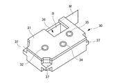
図1は、本発明に係る実施形態の印刷装置1の斜視図である。印刷装置1は、被印刷媒体Mに印刷を行うサーマルヘッド10を備えるものであり、例えば、長尺状の被印刷媒体Mに、シングルパス方式で印刷を行うラベルプリンタである。
FIG. 1 is a perspective view of the
以下では、インクリボンRを使用する熱転写方式のラベルプリンタを例にして説明するが、印刷方式は特に限定されず、例えば、感熱紙を使用する感熱方式であってもよい。
また、被印刷媒体Mは、例えば、接着層を有する基材と、接着層を覆うように剥離可能に基材に貼付された剥離紙とを有するテープ部材であってもよく、離型紙なしのテープ部材であってもよい。
In the following, a heat transfer type label printer using the ink ribbon R will be described as an example, but the printing method is not particularly limited, and for example, a heat sensitive method using thermal paper may be used.
Further, the printing medium M may be, for example, a tape member having a base material having an adhesive layer and a release paper removably attached to the base material so as to cover the adhesive layer, without a release paper. It may be a tape member.
印刷装置1は、図1に示すように、装置筐体2と、入力部3と、表示部4と、開閉蓋18と、カセット収納部19とを備える。
装置筐体2の上面には、入力部3、表示部4、及び閉蓋18が配置されている。
As shown in FIG. 1, the
An
また、図示しないが、装置筐体2には、電源コード接続端子、外部機器接続端子、記憶媒体挿入口等が設けられている。
Further, although not shown, the
さらに、印刷装置1は、長尺方向に沿って被印刷媒体Mに印刷を行う長尺方向印刷モードと、幅方向に沿って被印刷媒体Mに印刷を行う幅方向印刷モードと、を選択することが可能になっており、例えば、長尺方向印刷モード及び幅方向印刷モードの選択は、入力部3に対する入力によって実現される。
Further, the
入力部3は、入力キー、十字キー、変換キー、決定キーなどの種々のキーを備える。表示部4は、例えば液晶表示パネルであり、入力部3からの入力に対応する文字等、各種設定のための選択メニュー、各種処理に関するメッセージ等を表示する。
The
また、印刷中には、被印刷媒体Mへの印刷が指示された文字や図形等(以下、文字、図形及び記号等を指して図形文字という場合がある。)の内容が表示され、印刷処理の進捗状況が表示されてもよい。
なお、表示部4にはタッチパネルユニットが設けられていてもよく、その場合、表示部4を入力部3の一部として看做してもよい。
Further, during printing, the contents of characters, figures, etc. (hereinafter, characters, figures, symbols, etc., which may be referred to as graphic characters) instructed to be printed on the print medium M are displayed, and printing processing is performed. The progress of is displayed.
The
また、表示部4は、印刷装置1の異常が検知されたときに所定のメッセージを表示して、印刷装置1の異常を利用者に報知してもよい。
即ち、表示部4は、印刷装置1の異常を報知する報知部である。
Further, the
That is, the
開閉蓋18は、カセット収納部19の上部に開閉可能に配置されている。開閉蓋18は、ボタン18aを押下されることにより開放される。
The opening /
開閉蓋18には、この開閉蓋18が閉じた状態でもカセット収納部19にテープカセット30(図2参照)が収納されているか否かを目視で確認可能とするために、窓18bが形成されている。
A
また、装置筐体2の側面には、排出口2aが形成されている。印刷装置1内で印刷が行われた被印刷媒体Mは、排出口2aから装置外へ排出される。
Further, a
図2は印刷装置1に収納されるテープカセット30の斜視図であり、図3は印刷装置1のカセット収納部19の斜視図であり、図4は印刷装置1の断面図である。
FIG. 2 is a perspective view of the
図2に示すテープカセット30は、図3に示すカセット収納部19に着脱自在に収納され、テープカセット30がカセット収納部19に収納された状態は、図4に示すようになる。
The
テープカセット30は、図2に示すように、サーマルヘッド被挿入部36及び係合部37が形成された、被印刷媒体MとインクリボンRを収容するカセットケース31を有する。
As shown in FIG. 2, the
カセットケース31には、テープコア32とインクリボン供給コア34とインクリボン巻取りコア35とが設けられている。
The
被印刷媒体Mは、カセットケース31内部のテープコア32にロール状に巻かれている(図4参照)。
The print medium M is wound around the
また、熱転写用のインクリボンRは、その先端がインクリボン巻取りコア35に巻きつけられた状態で、カセットケース31内部のインクリボン供給コア34にロール状に巻かれている(図4参照)。
Further, the ink ribbon R for thermal transfer is wound around the ink
装置筐体2のカセット収納部19には、図3に示すように、テープカセット30を所定の位置で支持するための複数のカセット受け部20が設けられている。
As shown in FIG. 3, the
また、カセット受け部20には、テープカセット30が収容するテープ(被印刷媒体M)の幅を認識するためのテープ幅認識スイッチ24が設けられている。
Further, the
テープ幅認識スイッチ24は、カセットの形状に基づいて長尺状の被印刷媒体Mの幅方向の幅(第1長さt1)を認識する幅認識部である。
The tape
カセット収納部19には、さらに、複数の発熱素子10aを有し、被印刷媒体Mに印刷を行うサーマルヘッド10と、被印刷媒体Mを搬送する搬送部であるプラテンローラ21と、テープコア係合軸22と、インクリボン巻取り駆動軸23が設けられている。
The
また、複数の発熱素子10aは、図示しないが、テープカセット30がカセット収納部19に収納された状態では、被印刷媒体Mの長尺方向と対応するライン上及び被印刷媒体Mの幅方向と対応するライン上に配列されている。
Although the plurality of
さらに、サーマルヘッド10には、サーミスタ13が埋め込まれている。サーミスタ13は、サーマルヘッド10の温度を測定するヘッド温度測定部である。
Further, a
テープカセット30がカセット収納部19に収納された状態では、図4に示すように、カセットケース31に設けられた係合部37がカセット収納部19に設けられたカセット受け部20に支持されて、サーマルヘッド10がカセットケース31に形成されたサーマルヘッド被挿入部36に挿入される。
In a state where the
また、テープコア係合軸22には、テープカセット30のテープコア32が係合し、さらに、インクリボン巻取り駆動軸23には、インクリボン巻取りコア35が係合する。
Further, the
印刷装置1に印刷指示が入力されると、被印刷媒体Mは、プラテンローラ21の回転によりテープコア32から繰り出される。
この際、インクリボン巻取り駆動軸23がプラテンローラ21に同調して回転することで、被印刷媒体MとともにインクリボンRがインクリボン供給コア34から繰り出される。
When a printing instruction is input to the
At this time, the ink ribbon winding
これにより、被印刷媒体MとインクリボンRは重なった状態で搬送される。そして、サーマルヘッド10とプラテンローラ21の間を通過する際にインクリボンRがサーマルヘッド10によって加熱されることで、インクが被印刷媒体Mに転写され、印刷が行われる。
As a result, the print medium M and the ink ribbon R are conveyed in an overlapping state. Then, when the ink ribbon R is heated by the
サーマルヘッド10とプラテンローラ21の間を通過した使用済みのインクリボンRは、インクリボン巻取りコア35に巻き取られる。
The used ink ribbon R that has passed between the
一方、サーマルヘッド10とプラテンローラ21の間を通過した印刷済みの被印刷媒体Mは、ハーフカット機構16及びフルカット機構17で切断され、排出口2aから排出される。
On the other hand, the printed medium M to be printed that has passed between the
図5は、印刷装置1のハードウェア構成を示したブロック図である。
印刷装置1は、上述の入力部3、表示部4、サーマルヘッド10、サーミスタ13、ハーフカット機構16、フルカット機構17、プラテンローラ21、テープ幅認識スイッチ24に加えて、制御部5、ROM6(Read Only Memory)、RAM7(Random Access Memory)、表示部駆動回路8、ヘッド駆動回路9、搬送用モータ駆動回路11、ステッピングモータ12、カッターモータ駆動回路14、カッターモータ15、及び、電源回路40を備える。
なお、少なくとも制御部5、ROM6、及びRAM7は、印刷装置1のコンピュータを構成する。
FIG. 5 is a block diagram showing a hardware configuration of the
In addition to the above-mentioned
At least the control unit 5, the
制御部5は、例えばCPU(Central Processing Unit)などのプロセッサ5aを含む。
また、制御部5は、ROM6に記憶されているプログラムをプロセッサ5aに実行させることで、印刷装置1の各部の動作を制御する。
The control unit 5 includes a
Further, the control unit 5 controls the operation of each unit of the
制御部5は、例えば、制御信号(ストローブ信号、ラッチ信号、クロック信号)と印刷データをヘッド駆動回路9へ供給し、ヘッド駆動回路9を介してサーマルヘッド10を制御する。
For example, the control unit 5 supplies control signals (strobe signal, latch signal, clock signal) and print data to the head drive circuit 9, and controls the
また、制御部5は、モータ駆動回路(搬送用モータ駆動回路11、カッターモータ駆動回路14)を介してモータ(ステッピングモータ12、カッターモータ15)を制御する。
Further, the control unit 5 controls the motors (stepping
制御部5の各機能は、専用のモジュール(ハードウェア)で実現されていてもよく、また、ROM6に格納されているプログラム(ソフトウェア)をプロセッサ5aが実行することにより実現されてもよい。
Each function of the control unit 5 may be realized by a dedicated module (hardware), or may be realized by the
ROM6は、被印刷媒体Mに印刷を行うプログラム、プログラムの実行に必要な各種データ(例えば、フォント、通電テーブル、図形文字間の間隔、所定幅の余白、サーマルヘッド10の複数の発熱素子10aが設けられた領域の幅方向の幅等)を記憶する。
The
ROM6は、制御部5によって読取り可能なプログラムが記憶された記憶媒体としても機能する。
The
RAM7は、ユーザによって入力された図形文字パターンを含む入力データ、及び、テープ幅認識スイッチ24によって認識された長尺状の被印刷媒体Mの幅方向の第1長さt1等を一時的に記憶するものである。
さらに、RAM7は、表示データを一時的に記憶する表示データ記憶部を含む。
The RAM 7 temporarily stores the input data including the graphic character pattern input by the user, the first length t1 in the width direction of the long print medium M recognized by the tape
Further, the RAM 7 includes a display data storage unit that temporarily stores display data.
表示部駆動回路8は、RAM7に記憶された表示データに基づいて表示部4を制御する。
そして、表示部4は、表示部駆動回路8の制御下で、例えば、印刷処理の進捗状況が認識可能な態様で印刷内容を表示してもよい。
The display unit drive circuit 8 controls the
Then, the
ヘッド駆動回路9は、制御部5から供給された制御信号と印刷データに基づいてサーマルヘッド10を駆動するヘッド駆動部であり、印刷データを保持するラッチ回路9aを備えている。
The head drive circuit 9 is a head drive unit that drives the
より詳細には、ヘッド駆動回路9前側ローブ信号がONである通電期間中に、ラッチ回路9aから出力された印刷データに基づいて複数の発熱素子10aに対して電圧の通電又は非通電を制御する。
More specifically, during the energization period in which the front lobe signal of the head drive circuit 9 is ON, voltage energization or de-energization is controlled for the plurality of
サーマルヘッド10は、被印刷媒体Mの長尺方向及び幅方向に沿って配列された複数の発熱素子10aを有する印刷部であり、ヘッド駆動回路9が、制御部5から供給されたストローブ信号により指定される通電期間中に、ラッチ回路9aから出力された印刷データに応じて発熱素子10aへ電流を選択的に流すことで、発熱素子10aが発熱してインクリボンRを加熱する。
これにより、サーマルヘッド10は、熱転写により被印刷媒体Mに1ラインずつ印刷を行う。
即ち、本実施形態の印刷装置1は、サーマルラインプリンタである。
The
As a result, the
That is, the
搬送用モータ駆動回路11は、ステッピングモータ12を駆動し、ステッピングモータ12は、プラテンローラ21を回転させる。
The transport motor drive circuit 11 drives the stepping
そして、プラテンローラ21は、ステッピングモータ12の動力によって回転し、被印刷媒体Mの長尺方向に被印刷媒体Mを搬送する搬送部である。
The
カッターモータ駆動回路14は、カッターモータ15を駆動する。
そして、ハーフカット機構16及びフルカット機構17は、カッターモータ15の動力によって動作し、被印刷媒体Mをハーフカット又はフルカットする。
なお、フルカットとは、被印刷媒体Mの基材を剥離紙とともに幅方向に沿って切断する動作のことであり、ハーフカットは、基材のみを幅方向に沿って切断する動作のことである。
The cutter
Then, the half-
The full cut is an operation of cutting the base material of the printing medium M together with the release paper along the width direction, and the half cut is an operation of cutting only the base material along the width direction. is there.
電源回路40は、ACアダプタ50からの直流電圧(例えば、24V)から出力電圧を生成し、印刷装置1の各部に電力を供給する電源部である。
The
以下、図6〜図18を参照しながら本発明に係る実施形態の印刷装置1に用いられる幅方向印刷モードについて詳細に説明する。
なお、印刷装置1の長尺方向印刷モードについては、一般的なものであるため説明を省略する。
Hereinafter, the width direction printing mode used in the
The long direction printing mode of the
予めテープ幅認識スイッチ24は、テープカセット30がカセット収納部19に収納された状態で、長尺状の被印刷媒体Mの幅方向の第1長さt1(図9参照)を認識し、認識された第1長さt1がRAM7に一時的に記憶される。
The tape
先ず、ユーザが入力部3にて図形文字パターンの入力を行い、ユーザによって入力された複数の図形文字パターンを含む入力データがRAM7に一時的に記憶される。
そして、その後、ユーザが幅方向印刷モードを選択すると、幅方向印刷が開始される。
First, the user inputs a graphic character pattern in the
Then, when the user selects the width direction printing mode, the width direction printing is started.
<幅方向印刷>
以下、幅方向印刷の全体の流れを示すフローチャートである図6を参照しながら、具体的に、幅方向印刷の内容について説明する。
<Printing in the width direction>
Hereinafter, the content of the width direction printing will be specifically described with reference to FIG. 6, which is a flowchart showing the entire flow of the width direction printing.
例えば、サーマルヘッド10の複数の発熱素子10aが設けられた領域の幅方向の第2長さt2は、装置構成であるため予めわかっており、ROM6に記憶されている。
For example, the second length t2 in the width direction of the region provided with the plurality of
そこで、制御部5は、ステップS10において、ROM6から読み出したサーマルヘッド10の複数の発熱素子10aが設けられた領域の幅方向の第2長さt2と、RAM7から読み出した長尺状の被印刷媒体Mの幅方向の第1長さt1とを比較する。
Therefore, in step S10, the control unit 5 has a second length t2 in the width direction of the region in which the plurality of
そして、制御部5は、図9に示すように、第2長さt2が第1長さt1以上である場合(YES)、即ち、サーマルヘッド10による印刷が被印刷媒体Mの幅方向の全体に対して可能である場合、第1印刷データを作成するための第1印刷データ作成処理(ステップS20)を行う。
なお、第1印刷データ作成処理(ステップS20)の詳細については後述する。
Then, as shown in FIG. 9, the control unit 5 determines that the second length t2 is equal to or greater than the first length t1 (YES), that is, printing by the
The details of the first print data creation process (step S20) will be described later.
一方、制御部5は、第2長さt2が第1長さt1よりも小さい場合(NO)、即ち、サーマルヘッド10による印刷が被印刷媒体Mの幅方向の全体に対して可能ではない場合、第2印刷データを作成するための第2印刷データ作成処理(ステップS30)を行う。
なお、第2印刷データ作成処理(ステップS30)の詳細については後述する。
On the other hand, in the control unit 5, when the second length t2 is smaller than the first length t1 (NO), that is, when printing by the
The details of the second print data creation process (step S30) will be described later.
そして、制御部5は、第1印刷データ作成処理(ステップS20)又は第2印刷データ作成処理(ステップS30)が終了すると、印刷・カット処理(ステップS40)に移行する。 Then, when the first print data creation process (step S20) or the second print data creation process (step S30) is completed, the control unit 5 shifts to the print / cut process (step S40).
ステップS40に移行すると、ヘッド駆動回路9が、制御部5の作成した第1印刷データ又は第2印刷データに従って、サーマルヘッド10を駆動させ、被印刷媒体Mに印刷を行うとともに、カッターモータ駆動回路14が、制御部5から供給される制御信号に基づいて、カッターモータ15を駆動させて、ハーフカット機構16及びフルカット機構17を動作させ、印刷済みの被印刷媒体Mを1ラインずつハーフカット又はフルカットし、ステップS40が終わると、幅方向印刷が終了する。
In step S40, the head drive circuit 9 drives the
<第1印刷データ作成処理>
次に、第1印刷データ作成処理(ステップS20)のフローチャートである図7を参照しながら、具体的に、第1印刷データ作成処理(ステップS20)の内容について説明する。
<First print data creation process>
Next, the contents of the first print data creation process (step S20) will be specifically described with reference to FIG. 7, which is a flowchart of the first print data creation process (step S20).
先ず、ステップS21において、制御部5は、RAM7から読み出した入力データに基づいた複数の図形文字パターンの前後にROM6から読み出した所定幅yの余白を付加した全体データの全体印刷長さである第3長さt3と、RAM7から読み出した長尺状の被印刷媒体Mの幅方向の第1長さt1と、を比較する。
First, in step S21, the control unit 5 is the total print length of the entire data in which a margin of a predetermined width y read from the
そして、図9に示すように、全体データの全体印刷長さである第3長さt3が被印刷媒体Mの幅方向の第1長さt1以下である場合(YES)、1ラインの印刷データを作成する1ライン第1印刷データ作成処理(ステップS22)を行う。
なお、1ライン第1印刷データ作成処理(ステップS22)の詳細については後述する。
Then, as shown in FIG. 9, when the third length t3, which is the total print length of the entire data, is equal to or less than the first length t1 in the width direction of the print medium M (YES), one line of print data. 1 line 1st print data creation process (step S22) is performed.
The details of the 1-line first print data creation process (step S22) will be described later.
一方、第3長さt3が第1長さt1よりも大きい場合(NO)、複数ラインの印刷データを作成する複数ライン第1印刷データ作成処理(ステップS23)を行う。
なお、複数ライン第1印刷データ作成処理(ステップS23)の詳細については後述する。
On the other hand, when the third length t3 is larger than the first length t1 (NO), the plurality of lines first print data creation process (step S23) for creating print data of a plurality of lines is performed.
The details of the plurality of lines first print data creation process (step S23) will be described later.
1ライン第1印刷データ作成処理(ステップS22)又は複数ライン第1印刷データ作成処理(ステップS23)が終了すると、図6に示す幅方向印刷のフローチャートに戻る。 When the 1-line first print data creation process (step S22) or the plurality of line 1st print data creation process (step S23) is completed, the process returns to the flowchart of width direction printing shown in FIG.
<1ライン第1印刷データ作成処理>
次に、第1印刷データ作成処理(ステップS20)における1ライン第1印刷データ作成処理(ステップS22)のフローチャートである図8を参照しながら、具体的に、1ライン印刷データ作成処理(ステップS22)の内容について説明する。
なお、図9は、1ライン第1印刷データに従ってマークmが付加されて幅方向に沿って印刷される被印刷媒体Mのイメージ図である。
<1st line 1st print data creation process>
Next, with reference to FIG. 8 which is a flowchart of the 1-line first print data creation process (step S22) in the 1st print data creation process (step S20), specifically, the 1-line print data creation process (step S22). ) Will be explained.
Note that FIG. 9 is an image diagram of the print medium M to which the mark m is added according to the first print data of one line and printed along the width direction.
先ず、ステップS221において、制御部5は、入力データに基づいた複数の図形文字パターンの前後に所定幅yの余白を付加した全体データを90度回転して被印刷媒体Mの幅方向に沿って展開させる。 First, in step S221, the control unit 5 rotates the entire data by adding a margin of a predetermined width y before and after the plurality of graphic character patterns based on the input data by 90 degrees along the width direction of the print medium M. Deploy.
次に、制御部5は、ステップS222において、図9に示すように、展開させた全体データを印刷後に被印刷媒体Mの幅方向の一端(左端)側に一致させるようにし、一端(左端)側に所定幅yの余白ができるようにした印刷データを作成する。 Next, in step S222, the control unit 5 aligns the developed overall data with one end (left end) side in the width direction of the print medium M after printing, as shown in FIG. 9, and one end (left end). Print data is created so that a margin of a predetermined width y is formed on the side.
そして、制御部5は、ステップS223において、全体データの全体印刷長さである第3長さt3が被印刷媒体Mの幅方向の第1長さt1と同じであるかを判定する。
ここで、制御部5は、第3長さt3が第1長さt1と同じである場合(YES)、ステップS225に移行し、図9に示すように、第3長さt3が第1長さt1と同じではない場合(NO)、ステップS224に移行する。
Then, in step S223, the control unit 5 determines whether the third length t3, which is the total print length of the entire data, is the same as the first length t1 in the width direction of the print medium M.
Here, when the third length t3 is the same as the first length t1 (YES), the control unit 5 proceeds to step S225, and as shown in FIG. 9, the third length t3 is the first length. If it is not the same as t1, the process proceeds to step S224.
ステップS224に移行した場合、制御部5は、図9に示すように、印刷後に被印刷媒体Mの幅方向の一端(左端)からマークmまでの距離が全体データの全体印刷長さである第3長さt3になるように、マークmに関する情報を印刷データに付加し、その後、制御部5は、ステップS225において、印刷データにマークmに関する情報を付加したものを、1ライン第1印刷データとする。 When the process proceeds to step S224, as shown in FIG. 9, the control unit 5 has the total print length of the entire data in which the distance from one end (left end) of the print medium M in the width direction to the mark m after printing is the total print length of the entire data. Information about the mark m is added to the print data so as to have a length t3, and then, in step S225, the control unit 5 adds the information about the mark m to the print data and adds the information about the mark m to the 1-line first print data. And.
一方、第3長さt3が第1長さt1と同じであり、ステップS223から、ステップS225に移行した場合、制御部5は、ステップS225において、印刷データそのものを1ライン第1印刷データとする。 On the other hand, when the third length t3 is the same as the first length t1 and the process shifts from step S223 to step S225, the control unit 5 sets the print data itself as the 1-line first print data in step S225. ..
そして、ステップS225が終了すると、図7に示す第1印刷データ作成処理(ステップS20)のフローチャートに戻る。 Then, when step S225 is completed, the process returns to the flowchart of the first print data creation process (step S20) shown in FIG. 7.
このように第1印刷データ作成処理(ステップS20)における1ライン印刷データ作成処理(ステップS22)では、全体データの全体印刷長さである第3長さt3が被印刷媒体Mの幅方向の第1長さt1と同じである場合、印刷済みの被印刷媒体Mをハーフカット又はフルカットするだけでよい状態のため、1ライン第1印刷データに従って幅方向に沿って印刷される被印刷媒体Mに全体印刷長さになるような全体データの端部を示すマークmが付加されない。 As described above, in the one-line print data creation process (step S22) in the first print data creation process (step S20), the third length t3, which is the total print length of the entire data, is the third in the width direction of the print medium M. When the length is the same as t1, the printed medium M to be printed needs only be half-cut or full-cut. Therefore, the printed medium M printed along the width direction according to the first print data of one line. Is not added with a mark m indicating the end of the entire data so as to have the entire print length.
一方、全体データの全体印刷長さである第3長さt3が被印刷媒体Mの幅方向の第1長さt1よりも小さい場合、左右の余白を同じにするためには、被印刷媒体Mをハーフカット又はフルカットした後に、余白が合うように、さらに切り取る必要があるため、図9に示すように、1ライン第1印刷データに従って幅方向に沿って印刷される被印刷媒体Mに全体印刷長さになるような全体データの端部を示すマークmが付加され、そのマークmに従って切り取りを行うだけで、所定幅yの余白の状態とすることができる。 On the other hand, when the third length t3, which is the total print length of the entire data, is smaller than the first length t1 in the width direction of the print medium M, the print medium M is required to have the same left and right margins. After half-cutting or full-cutting, it is necessary to further cut so that the margins match. Therefore, as shown in FIG. 9, the entire print medium M is printed along the width direction according to the first print data of one line. A mark m indicating the end of the entire data so as to have a print length is added, and a margin state of a predetermined width y can be obtained only by cutting according to the mark m.
<複数ライン第1印刷データ作成処理>
次に、第1印刷データ作成処理(ステップS20)における複数ライン第1印刷データ作成処理(ステップS23)のフローチャートである図10を参照しながら、具体的に、複数ライン第1印刷データ作成処理(ステップS23)の内容について説明する。
<Multiple line first print data creation process>
Next, with reference to FIG. 10 which is a flowchart of the plurality of lines first print data creation process (step S23) in the first print data creation process (step S20), specifically, the plurality of lines first print data creation process (step S20). The contents of step S23) will be described.
なお、図11は2ライン第1印刷データに従ってマークmが付加されて幅方向に沿って印刷される被印刷媒体Mのイメージ図であり、図12は3ライン第1印刷データに従ってマークmが付加されて幅方向に沿って印刷される被印刷媒体Mのイメージ図である。 FIG. 11 is an image diagram of the print medium M to which the mark m is added according to the first print data of the second line and printed along the width direction, and FIG. 12 is an image diagram of the medium M to be printed according to the first print data of the third line. It is an image diagram of the print medium M printed along the width direction.
先ず、制御部5は、ステップS231において、入力データに基づいた複数の図形文字パターンの前後に所定幅yの余白を付加した全体データを、各々が被印刷媒体Mの幅方向の第1長さt1内に収まるように分割する。
なお、ステップS231での全体データを分割して分割された複数のデータを作成する処理では、複数の図形文字パターンの隣接する図形文字の中間位置で分割したときに、第1長さt1内に収まる最大の幅となるように、それぞれのデータが作成される。
First, in step S231, the control unit 5 adds a margin of a predetermined width y before and after the plurality of graphic character patterns based on the input data, and each of them has the first length in the width direction of the print medium M. Divide so that it fits within t1.
In the process of dividing the entire data in step S231 to create a plurality of divided data, when the entire data is divided at the intermediate position of the adjacent graphic characters of the plurality of graphic character patterns, the data is within the first length t1. Each data is created so that it has the maximum width that fits.
例えば、図11に示すように、全体データを2分割することで第1長さt1内に収める分割されたデータにすることができる場合、つまり、前側の分割データ(余白+ABCD)と後側の分割データ(EF+余白)に分割する場合、前側の分割データは、隣接する図形文字であるDとEの中間位置で分割した場合が第1長さt1内に収まる最大の幅となるため、前側の分割データと後側の分割データの切り替り目がDとEの中間位置になっている。 For example, as shown in FIG. 11, when the entire data can be divided into two to make the divided data to be contained within the first length t1, that is, the front divided data (margin + ABCD) and the rear divided data. When dividing into divided data (EF + margin), the divided data on the front side has the maximum width that fits within the first length t1 when divided at the intermediate position between the adjacent graphic characters D and E, so the front side The transition between the divided data of the above and the divided data on the rear side is at an intermediate position between D and E.
同様に、図12に示すように、全体データを3分割に分割することで第1長さt1内に収める分割されたデータにすることができる場合、つまり、前側の分割データ(余白+ABCD)と中間の分割データ(EFGH)と後側の分割データ(IJKL+余白)とに分割する場合、前側の分割データは、隣接する図形文字であるDとEの中間位置で分割した場合が第1長さt1内に収まる最大の幅となるため、前側の分割データと中間の分割データの切り替り目がDとEの中間位置になっているとともに、中間の分割データは、隣接する図形文字であるHとIの中間位置で分割した場合が第1長さt1内に収まる最大の幅となるため、中間の分割データと後側の分割データの切り替り目がHとIの中間位置になっている。
なお、全体データを、各々が第1長さt1内に収まるように分割したときの分割数が4分割以上であった場合には、中間の分割データが複数になるだけである。
Similarly, as shown in FIG. 12, when the entire data can be divided into three parts so that the divided data can be stored in the first length t1, that is, with the front side divided data (margin + ABCD). When dividing into the middle divided data (EFGH) and the rear divided data (IJKL + margin), the front divided data has the first length when it is divided at the intermediate position between the adjacent graphic characters D and E. Since it is the maximum width that fits within t1, the transition between the front division data and the intermediate division data is at the intermediate position between D and E, and the intermediate division data is H, which is an adjacent graphic character. Since the maximum width that fits within the first length t1 is obtained when divided at the intermediate position between and I, the transition between the intermediate divided data and the rear divided data is at the intermediate position between H and I. ..
If the number of divisions when the entire data is divided so as to fit within the first length t1 is 4 or more, the number of intermediate division data is only a plurality.
次に、制御部5は、ステップS232において、分割された複数のデータを90度回転して被印刷媒体Mの幅方向に沿って展開させる。 Next, in step S232, the control unit 5 rotates the plurality of divided data by 90 degrees and develops them along the width direction of the print medium M.
そして、制御部5は、ステップS233において、90度回転された前側の分割データをセットする。 Then, in step S233, the control unit 5 sets the split data on the front side rotated by 90 degrees.
続いて、制御部5は、ステップS234において、図11又は図12に示すように、前側の分割データの切り替り目が被印刷媒体Mの幅方向の他端(右端)に一致するようにした前側の印刷データを作成する。
なお、このように作成された前側の印刷データは、被印刷媒体Mの幅方向の他端(右端)から最も被印刷媒体Mの幅方向の他端側に位置する図形文字パターンまでの距離が図形文字パターン間の間隔xの1/2となっている。
Subsequently, in step S234, the control unit 5 made the transition of the divided data on the front side coincide with the other end (right end) in the width direction of the print medium M, as shown in FIGS. 11 or 12. Create print data on the front side.
The print data on the front side created in this way has a distance from the other end (right end) of the print medium M in the width direction to the graphic character pattern located on the other end side of the print medium M in the width direction. The interval x between graphic character patterns is 1/2.
そして、制御部5は、ステップS235において、印刷後に被印刷媒体Mの幅方向の一端(左端)から最も被印刷媒体Mの幅方向の一端側に位置する図形文字パターンまでの距離が所定幅yと同じであるかを判定し、印刷後に被印刷媒体Mの幅方向の一端(左端)から最も被印刷媒体Mの幅方向の一端側に位置する図形文字パターンまでの距離が所定幅yと同じである場合(YES)にはステップS237に移行する。 Then, in step S235, the control unit 5 determines that the distance from one end (left end) of the print medium M in the width direction to the graphic character pattern located on the one end side in the width direction of the print medium M after printing is a predetermined width y. The distance from one end (left end) in the width direction of the print medium M to the graphic character pattern located on the one end side in the width direction of the print medium M after printing is the same as the predetermined width y. If (YES), the process proceeds to step S237.
一方、制御部5は、印刷後に被印刷媒体Mの幅方向の一端(左端)から最も被印刷媒体Mの幅方向の一端側に位置する図形文字パターンまでの距離が所定幅yと同じではない場合(NO)にはステップS236に移行して、図11又は図12に示すように、印刷後に最も被印刷媒体Mの幅方向の一端側に位置する図形文字パターンからマークmまでの距離が所定幅yとなる位置にマークmが表示されるように、マークmに関する情報を前側の印刷データに付加し、その後、制御部5は、ステップS237において、前側の印刷データにマークmに関する情報を付加したものを、前側の第1印刷データとする。 On the other hand, in the control unit 5, the distance from one end (left end) of the printed medium M in the width direction to the graphic character pattern located on the one end side in the width direction of the printed medium M after printing is not the same as the predetermined width y. In the case (NO), the process proceeds to step S236, and as shown in FIGS. 11 or 12, the distance from the graphic character pattern located on one end side in the width direction of the print medium M after printing to the mark m is predetermined. Information about the mark m is added to the print data on the front side so that the mark m is displayed at a position having a width y, and then the control unit 5 adds information about the mark m to the print data on the front side in step S237. This is used as the first print data on the front side.
一方、ステップS235から、ステップS237に移行した場合、制御部5は、ステップS237において、前側の印刷データをそのまま前側の第1印刷データとする。 On the other hand, when the process shifts from step S235 to step S237, the control unit 5 uses the print data on the front side as the first print data on the front side in step S237.
引き続き、制御部5は、ステップS233’において、90度回転された次の分割データをセットする。 Subsequently, the control unit 5 sets the next divided data rotated by 90 degrees in step S233'.
そして、制御部5は、ステップS234’において、セットされた次の分割データが中間の分割データであるかを判定する。
ここで、制御部5は、次の分割データが中間の分割データである場合(YES)にはステップS235’に移行し、一方、次の分割データが中間の分割データではない場合(NO)、つまり、後側の分割データである場合にはステップS234”に移行する。
Then, in step S234', the control unit 5 determines whether the next set divided data is the intermediate divided data.
Here, the control unit 5 proceeds to step S235'when the next divided data is the intermediate divided data (YES), while the control unit 5 proceeds to step S235'when the next divided data is not the intermediate divided data (NO). That is, in the case of the divided data on the rear side, the process proceeds to step S234 ”.
そして、ステップS235’に移行した場合、図12に示すように、制御部5は、中間の分割データの後側の切り替り目が被印刷媒体Mの幅方向の他端(右端)に一致するようにした中間の印刷データを作成する。
なお、このように作成された中間の印刷データは、被印刷媒体Mの幅方向の他端(右端)から最も被印刷媒体Mの幅方向の他端側に位置する図形文字パターンまでの距離が図形文字パターン間の間隔xの1/2となっている。
Then, when the process proceeds to step S235', as shown in FIG. 12, the control unit 5 coincides with the other end (right end) of the print medium M in the width direction at the rearmost transition of the intermediate division data. Create intermediate print data as described above.
The intermediate print data created in this way has a distance from the other end (right end) of the print medium M in the width direction to the graphic character pattern located on the other end side of the print medium M in the width direction. The interval x between graphic character patterns is 1/2.
そして、制御部5は、ステップS236’において、印刷後に被印刷媒体Mの幅方向の一端(左端)から最も被印刷媒体Mの幅方向の一端側に位置する図形文字パターンまでの距離が間隔xの1/2と同じであるかを判定し、印刷後に被印刷媒体Mの幅方向の一端(左端)から最も被印刷媒体Mの幅方向の一端側に位置する図形文字パターンまでの距離が間隔xの1/2と同じである場合(YES)、ステップS238’に移行する。 Then, in step S236', the control unit 5 has an interval x of the distance from one end (left end) in the width direction of the print medium M to the graphic character pattern located on the one end side in the width direction of the print medium M after printing. It is determined whether it is the same as 1/2 of, and the distance from one end (left end) in the width direction of the print medium M to the graphic character pattern located on the one end side in the width direction of the print medium M after printing is the interval. If it is the same as 1/2 of x (YES), the process proceeds to step S238'.
一方、制御部5は、印刷後に被印刷媒体Mの幅方向の一端(左端)から最も被印刷媒体Mの幅方向の一端側に位置する図形文字パターンまでの距離が間隔xの1/2と同じではない場合(NO)にはステップS237’に移行して、図12に示すように、印刷後に最も被印刷媒体Mの幅方向の一端側に位置する図形文字パターンからマークmまでの距離が間隔xの1/2となる位置にマークmが表示されるように、マークmに関する情報を中間の印刷データに付加し、その後、制御部5は、ステップS238’において、中間の印刷データにマークmに関する情報を付加したものを、中間の第1印刷データとする。 On the other hand, in the control unit 5, the distance from one end (left end) of the printed medium M in the width direction to the graphic character pattern located on the one end side in the width direction of the printed medium M after printing is 1/2 of the interval x. If they are not the same (NO), the process proceeds to step S237', and as shown in FIG. 12, the distance from the graphic character pattern located on one end side in the width direction of the print medium M after printing is the distance from the mark m. Information about the mark m is added to the intermediate print data so that the mark m is displayed at a position that is 1/2 of the interval x, and then the control unit 5 marks the intermediate print data in step S238'. The data to which the information about m is added is used as the intermediate first print data.
一方、ステップS236’ から、ステップS238’に移行した場合には、制御部5は、中間の印刷データをそのまま中間の第1印刷データとする。 On the other hand, when the process shifts from step S236'to step S238', the control unit 5 uses the intermediate print data as it is as the intermediate first print data.
ステップS238’が終了すると、ステップS233’に戻る。
即ち、制御部5は、90度回転された次の分割データをセットする。
When step S238'is completed, the process returns to step S233'.
That is, the control unit 5 sets the next divided data rotated by 90 degrees.
なお、次の分割データが2番目の中間の分割データである場合には、ステップS234’からステップS238’が、再び、行われ、2番目の中間の第1印刷データが作成されることになる。
したがって、中間の分割データが複数存在する場合には、その中間の分割データの数分だけ中間の第1印刷データ(1番目の中間の第1印刷データ、2番目の中間の第1印刷データ・・・)が作成されることになる。
If the next divided data is the second intermediate divided data, steps S234'to step S238' are performed again, and the second intermediate first print data is created. ..
Therefore, when there are a plurality of intermediate division data, the intermediate first print data (the first intermediate first print data, the second intermediate first print data, and the number of intermediate division data are present.・ ・) Will be created.
一方、ステップS237又はステップS238’からステップS233’に移行してセットされた分割データが後側の分割データである場合、ステップS234’の判定がNOとなり、制御部5は、ステップS234”において、図11又は図12に示すように、後側の分割データの切り替り目が被印刷媒体Mの幅方向の一端(左端)に一致するようにした後側の印刷データを作成する。
なお、このようにして作成された後側の印刷データは、被印刷媒体Mの幅方向の一端(左端)から最も被印刷媒体Mの幅方向の一端側に位置する図形文字パターンまでの距離が図形文字パターン間の間隔xの1/2となっている。
On the other hand, when the divided data set by shifting from step S237 or step S238'to step S233'is the posterior divided data, the determination in step S234' becomes NO, and the control unit 5 determines in step S234 ". As shown in FIGS. 11 or 12, the print data on the rear side is created so that the transition of the divided data on the rear side coincides with one end (left end) in the width direction of the print medium M.
The print data on the rear side created in this way has a distance from one end (left end) in the width direction of the print medium M to the graphic character pattern located on the one end side in the width direction of the print medium M. The interval x between graphic character patterns is 1/2.
そして、制御部5は、ステップS235”において、印刷後に被印刷媒体Mの幅方向の他端(右端)から最も被印刷媒体Mの幅方向の他端側に位置する図形文字パターンまでの距離が所定幅yと同じであるかを判定し、印刷後に被印刷媒体Mの幅方向の他端(右端)から最も被印刷媒体Mの幅方向の他端側に位置する図形文字パターンまでの距離が所定幅yと同じである場合(YES)にはステップS237”に移行する。 Then, in step S235, the control unit 5 determines the distance from the other end (right end) of the print medium M in the width direction to the graphic character pattern located on the other end side of the print medium M in the width direction after printing. It is determined whether the width is the same as the predetermined width y, and after printing, the distance from the other end (right end) of the print medium M in the width direction to the graphic character pattern located on the other end side of the print medium M in the width direction is If it is the same as the predetermined width y (YES), the process proceeds to step S237 ”.
一方、制御部5は、印刷後に被印刷媒体Mの幅方向の他端(右端)から最も被印刷媒体Mの幅方向の他端側に位置する図形文字パターンまでの距離が所定幅yと同じではない場合(NO)にはステップS236”に移行して、図11又は図12に示すように、印刷後に最も被印刷媒体Mの幅方向の他端側に位置する図形文字パターンからマークmまでの距離が所定幅yとなる位置にマークmが表示されるように、マークmに関する情報を後側の印刷データに付加し、その後、制御部5は、ステップS237”において、後側の印刷データにマークmに関する情報を付加したものを、後側の第1印刷データとする。 On the other hand, after printing, the control unit 5 has the same distance from the other end (right end) of the print medium M in the width direction to the graphic character pattern located on the other end side of the print medium M in the width direction as the predetermined width y. If not (NO), the process proceeds to step S236 ”, and as shown in FIGS. 11 or 12, from the graphic character pattern located on the other end side of the print medium M in the width direction to the mark m after printing. Information about the mark m is added to the print data on the rear side so that the mark m is displayed at a position where the distance of is a predetermined width y, and then the control unit 5 performs the print data on the rear side in step S237 ”. The data to which the information about the mark m is added is used as the first print data on the rear side.
一方、ステップS235”から、ステップS237”に移行した場合には、制御部5は、後側の印刷データを後側の第1印刷データとする。 On the other hand, when the process shifts from step S235 "to step S237", the control unit 5 sets the print data on the rear side as the first print data on the rear side.
そして、ステップS237”が終了し、前側の第1印刷データ及び後側の第1印刷データを有する複数ライン第1印刷データ、又は、前側の第1印刷データ、中間の第1印刷データ(なお、中間の第1印刷データは複数の場合がある。)及び後側の第1印刷データを有する複数ライン第1印刷データが作成されると、図7に示す第1印刷データ作成処理(ステップS20)のフローチャートに戻る。 Then, step S237 ”is completed, and the plurality of line first print data having the front side first print data and the rear side first print data, or the front side first print data and the intermediate first print data (note that (There may be a plurality of first print data in the middle), and when the first print data of the plurality of lines having the first print data on the rear side is created, the first print data creation process (step S20) shown in FIG. Return to the flowchart of.
以上のような処理によって、図11及び図12に示すような印刷が行われる複数ライン第1印刷データが作成される。 By the above processing, the multi-line first print data to be printed as shown in FIGS. 11 and 12 is created.
そして、図11に示すような印刷の場合、印刷データの切り替り目が隣接する図形文字であるDとEの中間位置にあり、図形文字Dと被印刷媒体Mの幅方向の他端(右端)までの距離が図形文字の配列の間隔xの1/2となるように印刷されるものとなっているとともに、図形文字Eと被印刷媒体Mの幅方向の一端(左端)までの距離が図形文字の配列の間隔xの1/2となるように印刷されるものとなっている。 In the case of printing as shown in FIG. 11, the transition of the print data is at the intermediate position between the adjacent graphic characters D and E, and the other end (right end) of the graphic character D and the print medium M in the width direction. ) Is printed so as to be 1/2 of the interval x of the graphic character arrangement, and the distance between the graphic character E and one end (left end) of the graphic character M in the width direction is It is printed so as to be 1/2 of the interval x of the arrangement of graphic characters.
したがって、1ライン目の印刷部分の被印刷媒体Mの幅方向の他端(右端)と2ライン目の印刷部分の被印刷媒体Mの幅方向の一端(左端)を当接させるように繋げるだけで、図形文字DとEとの間の間隔xが、他の図形文字パターン間の間隔xと同じにでき、被印刷媒体Mの端は機械的に作成された極めて正確な直線状態になっているため、繋ぎ目に隙間が発生することが抑制でき、見栄え良く繋げることができる。 Therefore, the other end (right end) of the printed portion of the first line in the width direction of the printed medium M and one end (left end) of the printed portion of the second line printed portion in the width direction are simply connected so as to be in contact with each other. Then, the space x between the graphic characters D and E can be made the same as the space x between the other graphic character patterns, and the edge of the print medium M becomes a mechanically created extremely accurate linear state. Therefore, it is possible to suppress the occurrence of gaps at the joints, and it is possible to connect them with good appearance.
また、前側の図形文字Aから余白を取った位置、及び、後側の図形文字Fから余白を取った位置には、マークmが印刷されることになるため、印刷後にそのマークmに沿って切り取りを行うだけで、繋げたときに全体データの全体印刷長さである第3長さt3とすることができる。 Further, since the mark m is printed at the position where the margin is taken from the graphic character A on the front side and the position where the margin is taken from the graphic character F on the rear side, the mark m is printed along the mark m after printing. By simply cutting, the third length t3, which is the total print length of the entire data when connected, can be obtained.
そして、図12に示す場合であっても同様に、印刷後に各第1印刷データ(前側の第1印刷データ、中間の第1印刷データ及び後側の第1印刷データ)に沿って印刷された部分を繋げるようにしたときに、第3長さt3にするとともに複数の図形文字パターンの間隔xを等しくするようにするための適切な位置にマークmが印刷されるようになっている。 Then, even in the case shown in FIG. 12, similarly, after printing, each first print data (first print data on the front side, first print data in the middle, and first print data on the rear side) was printed. When the parts are connected, the mark m is printed at an appropriate position so that the third length is t3 and the intervals x of the plurality of graphic character patterns are equalized.
このように、第1印刷データ作成処理(ステップS20)における複数ライン第1印刷データ作成処理(ステップS23)では、第3長さt3を分割し、各々が第1長さt1内に収まるようにした複数の第1印刷データが、印刷後に各第1印刷データに沿って印刷された部分を繋げるようにしたときに、第3長さt3にするとともに複数の図形文字パターンの間隔xが等しくなるような複数の印刷データ各々の端部を示すマークmが印刷される複数の第1印刷データを有する複数ライン第1印刷データの作成が行われている。 As described above, in the plurality of lines first print data creation process (step S23) in the first print data creation process (step S20), the third length t3 is divided so that each of them fits within the first length t1. When the plurality of first print data to be printed are connected to the printed parts along each first print data after printing, the third length is t3 and the spacing x of the plurality of graphic character patterns becomes equal. A plurality of lines of first print data having a plurality of first print data on which a mark m indicating an end of each of the plurality of print data is printed are being created.
したがって、ユーザはマークmに従って切り取りを行い、切り取りを行った各被印刷媒体Mを繋げるだけでよい。 Therefore, the user need only cut according to the mark m and connect the cut media to be printed.
なお、印刷データの切り替り目は、必ずしも、隣接する図形文字の中間位置である必要はない。
しかしながら、図12の中間の第1印刷データによる印刷部分(図形文字EFGHの印刷部分参照)を見るとわかるとおり、図形文字E側の部分は、印刷後にユーザがマークmに沿って切り取りを行うことになり、図形文字に近接してマークmが設けられていると、切り取りのときに繋げたときに見栄え上の問題がない範囲で微小に切り取り位置がズレただけでも図形文字の部分を傷つけることになる。
It should be noted that the transition of print data does not necessarily have to be at the intermediate position of adjacent graphic characters.
However, as can be seen from the printed portion of the first print data in the middle of FIG. 12 (see the printed portion of the graphic character EFGH), the portion on the graphic character E side is cut by the user along the mark m after printing. If the mark m is provided close to the graphic character, even if the cut position is slightly misaligned within the range where there is no problem in appearance when connected at the time of cutting, the graphic character part will be damaged. become.
一方、本実施形態のように、マークmが隣接する図形文字の中間位置に設けられるようになっていれば、そのように微小にズレた程度であれば、図形文字が傷つくことがないため、本実施形態のように、印刷データの切り替り目を隣接する図形文字の中間位置にしておくことが好ましい。 On the other hand, if the mark m is provided at an intermediate position between adjacent graphic characters as in the present embodiment, the graphic characters will not be damaged if the mark m is slightly displaced. As in the present embodiment, it is preferable to set the transition of print data at an intermediate position between adjacent graphic characters.
<第2印刷データ作成処理>
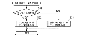
次に、第2印刷データ作成処理(ステップS30)のフローチャートである図13を参照しながら、図6の第2印刷データ作成処理(ステップS30)に移行したときの処理について説明する。
<Second print data creation process>
Next, with reference to FIG. 13, which is a flowchart of the second print data creation process (step S30), the process when the process shifts to the second print data creation process (step S30) of FIG. 6 will be described.
先に、図6を参照して説明したように、第2印刷データ作成処理(ステップS30)に移行する場合とは、サーマルヘッド10の複数の発熱素子10aが設けられた領域の幅方向の第2長さt2が被印刷媒体Mの幅方向の第1長さt1よりも小さい場合(NO)である。
As described above with reference to FIG. 6, the case of shifting to the second print data creation process (step S30) is the first in the width direction of the region where the plurality of
このため、1ラインで印刷を行うことになるのか、複数ラインに分割して印刷を行うことになるのかは第2長さt2を基準として決められることになり、以下、図13を参照しながら具体的に説明する。 Therefore, whether printing is performed on one line or divided into a plurality of lines is determined based on the second length t2. Hereinafter, with reference to FIG. This will be described in detail.
先ず、制御部5は、ステップS31において、RAM7から読み出した入力データに基づいた複数の図形文字パターンの前後にROM6から読み出した所定幅yの余白を付加した全体データの全体印刷長さである第3長さt3と、ROM6から読み出したサーマルヘッド10の複数の発熱素子10aが設けられた領域の幅方向の第2長さt2と、を比較する。
First, in step S31, the control unit 5 is the total print length of the entire data in which a margin of a predetermined width y read from the
そして、制御部5は、第3長さt3が第2長さt2以下である場合(YES)、1ライン第2印刷データを作成する1ライン第2印刷データ作成処理(ステップS32)を行う。
なお、1ライン第2印刷データ作成処理(ステップS32)の詳細については後述する。
Then, when the third length t3 is equal to or less than the second length t2 (YES), the control unit 5 performs the 1-line second print data creation process (step S32) for creating the 1-line second print data.
The details of the 1-line second print data creation process (step S32) will be described later.
一方、制御部5は、第3長さt3が第2長さt2よりも大きい場合(NO)、複数ライン第2印刷データを作成する複数ライン第2印刷データ作成処理(ステップS33)を行う。
なお、複数ライン第2印刷データ作成処理(ステップS33)の詳細については後述する。
On the other hand, when the third length t3 is larger than the second length t2 (NO), the control unit 5 performs the plurality of line second print data creation process (step S33) for creating the plurality of line second print data.
The details of the plurality of lines second print data creation process (step S33) will be described later.
そして、1ライン第2印刷データ作成処理(ステップS32)又は複数ライン第2印刷データ作成処理(ステップS33)が終了すると、図6に示す幅方向印刷のフローチャートに戻り、ステップS40において、作成された印刷データに従った印刷及びカット(ハーフカット又はフルカット)が行われ、全体の処理が終了することになる。 Then, when the 1-line second print data creation process (step S32) or the plurality of lines 2nd print data creation process (step S33) is completed, the process returns to the flow chart of the width direction printing shown in FIG. 6, and is created in step S40. Printing and cutting (half-cut or full-cut) are performed according to the print data, and the entire process is completed.
<1ライン第2印刷データ作成処理>
次に、第2印刷データ作成処理(ステップS30)における1ライン第2印刷データ作成処理(ステップS32)のフローチャートである図14を参照しながら、具体的に1ライン第2印刷データ作成処理(ステップS32)の内容について説明する。
なお、図15は、1ライン第2印刷データに従ってマークmが付加されて幅方向に沿って印刷される被印刷媒体Mのイメージ図である。
<1st line 2nd print data creation process>
Next, with reference to FIG. 14 which is a flowchart of the 1-line second print data creation process (step S32) in the 2nd print data creation process (step S30), specifically, the 1-line second print data creation process (step). The contents of S32) will be described.
Note that FIG. 15 is an image diagram of the print medium M to which the mark m is added according to the second print data of one line and printed along the width direction.
先ず、制御部5は、ステップS321において、入力データに基づいた複数の図形文字パターンの前後に所定幅yの余白を付加した全体データを90度回転して被印刷媒体Mの幅方向に沿って展開させる。 First, in step S321, the control unit 5 rotates the entire data by adding a margin of a predetermined width y before and after the plurality of graphic character patterns based on the input data by 90 degrees along the width direction of the print medium M. Deploy.
次に、制御部5は、ステップS322において、図15に示すように、展開させた全体データを印刷後に被印刷媒体Mの幅方向の一端側に一致させるようにし、一端側に所定幅yの余白ができるようにした印刷データを作成する。 Next, in step S322, as shown in FIG. 15, the control unit 5 aligns the developed overall data with one end side in the width direction of the print medium M after printing, and has a predetermined width y on one end side. Create print data with margins.
このようにすると、先にも説明したように、第2印刷データ作成処理に移行している場合、サーマルヘッド10の複数の発熱素子10aが設けられた領域の幅方向の第2長さt2よりもが被印刷媒体Mの幅方向の第1長さt1のほうが大きいため、被印刷媒体Mの幅方向の他端(右端)側には、必ず余計な余りとなる部分が発生する。
In this way, as described above, when shifting to the second print data creation process, the second length t2 in the width direction of the region provided with the plurality of
そこで、制御部5は、ステップS323において、図15に示すように、印刷後に被印刷媒体Mの幅方向の一端(左端)からマークmまでの距離が全体データの全体印刷長さである第3長さt3になる位置にマークmが表示されるように、マークmに関する情報を印刷データに付加する。 Therefore, in step S323, as shown in FIG. 15, the control unit 5 has a third position in which the distance from one end (left end) of the print medium M in the width direction to the mark m after printing is the total print length of the entire data. Information about the mark m is added to the print data so that the mark m is displayed at a position having a length t3.
そして、制御部5は、ステップS324において、印刷データにマークmに関する情報を付加したものを、1ライン第2印刷データとし、ステップS324が終了すると、図13に示す第2印刷データ作成処理(ステップS30)のフローチャートに戻る。 Then, in step S324, the control unit 5 sets the print data to which the information about the mark m is added as the 1-line second print data, and when step S324 is completed, the second print data creation process (step) shown in FIG. Return to the flowchart of S30).
以上のような処理によって、作成された1ライン第2印刷データに従って、印刷が行われると、図15に示すような印刷となり、被印刷媒体Mに全体印刷長さになるような全体データの端部を示すマークmが付加されているため、そのマークmに沿って、ユーザは切り取りを行うだけで、所定幅yの余白の状態とすることができる。 When printing is performed according to the 1-line second print data created by the above processing, the printing is as shown in FIG. 15, and the end of the entire data such that the entire print length is obtained on the print medium M. Since the mark m indicating the portion is added, the user can obtain a margin state of a predetermined width y simply by cutting along the mark m.
<複数ライン第2印刷データ作成処理>
次に、第2印刷データ作成処理(ステップS30)における複数ライン第2印刷データ作成処理(ステップS33)のフローチャートである図16を参照しながら、具体的に、複数ライン第2印刷データ作成処理(ステップS33)の内容について説明する。
<Multiple line second print data creation process>
Next, with reference to FIG. 16 which is a flowchart of the plurality of lines second print data creation process (step S33) in the second print data creation process (step S30), specifically, the plurality of lines second print data creation process (step S30). The contents of step S33) will be described.
なお、図17は複数ライン第2印刷データの一例である2ライン第2印刷データに従ってマークmが付加されて幅方向に沿って印刷される被印刷媒体Mのイメージ図であり、図18は複数ライン第2印刷データの一例である3ラインの第2印刷データに従ってマークmが付加されて幅方向に沿って印刷される被印刷媒体Mのイメージ図である。 FIG. 17 is an image diagram of the printed medium M to which the mark m is added according to the two-line second print data, which is an example of the plurality of lines second print data, and is printed along the width direction. FIG. It is an image diagram of the print medium M which is printed along the width direction by adding a mark m according to the second print data of three lines which is an example of the second print data.
先ず、制御部5は、ステップS331において、入力データに基づいた複数の図形文字パターンの前後に所定幅yの余白を付加した全体データを、各々が第2長さt2内に収まるように分割する。
なお、ステップS331での全体データを分割して分割された複数のデータを作成する処理では、複数の図形文字パターンの隣接する図形文字の中間位置で分割したときに、第2長さt2内に収まる最大の幅となるように、それぞれのデータが作成される。
First, in step S331, the control unit 5 divides the entire data in which a margin of a predetermined width y is added before and after the plurality of graphic character patterns based on the input data so that each of them fits within the second length t2. ..
In the process of dividing the entire data in step S331 to create a plurality of divided data, when the entire data is divided at the intermediate position of the adjacent graphic characters of the plurality of graphic character patterns, the data is within the second length t2. Each data is created so that it has the maximum width that fits.
例えば、図17に示すように、全体データを2分割することで第2長さt2内に収める分割されたデータにすることができる場合、つまり、前側の分割データ(余白+ABC)と後側の分割データ(DE+余白)に分割する場合、前側の分割データは、隣接する図形文字であるDとEの中間位置で分割した場合が第2長さt2内に収まる最大の幅となるため、前側の分割データと後側の分割データの切り替り目がDとEの中間位置になっている。 For example, as shown in FIG. 17, when the entire data can be divided into two to obtain the divided data to be stored in the second length t2, that is, the front divided data (margin + ABC) and the rear divided data. When dividing into divided data (DE + margin), the divided data on the front side has the maximum width that fits within the second length t2 when divided at the intermediate position between the adjacent graphic characters D and E, so the front side The transition between the divided data of the above and the divided data on the rear side is at an intermediate position between D and E.
同様に、図18に示すように、全体データを3分割に分割することで第2長さt2内に収める分割されたデータにすることができる場合、つまり、前側の分割データ(余白+ABC)と中間の分割データ(DEF)と後側の分割データ(GH+余白)とに分割する場合、前側の分割データは、隣接する図形文字であるDとEの中間位置で分割した場合が第2長さt2内に収まる最大の幅となるため、前側の分割データと中間の分割データの切り替り目がCとDの中間位置になっているとともに、中間の分割データは、隣接する図形文字であるFとGの中間位置で分割した場合が第2長さt2内に収まる最大の幅となるため、中間の分割データと後側の分割データの切り替り目がFとGの中間位置になっている。
なお、全体データを、各々が第2長さt2内に収まるように分割したときの分割数が4分割以上であった場合には、中間の分割データが複数になるだけである。
Similarly, as shown in FIG. 18, when the entire data can be divided into three parts so that the divided data can be stored in the second length t2, that is, with the front side divided data (margin + ABC). When dividing into the middle divided data (DEF) and the rear divided data (GH + margin), the front divided data has the second length when it is divided at the intermediate position between the adjacent graphic characters D and E. Since it is the maximum width that fits within t2, the transition between the front division data and the intermediate division data is at the intermediate position between C and D, and the intermediate division data is the adjacent graphic character F. Since the maximum width that fits within the second length t2 is obtained when divided at the intermediate position between and G, the transition between the intermediate divided data and the rear divided data is the intermediate position between F and G. ..
If the total number of divisions is 4 or more when the entire data is divided so that each of them fits within the second length t2, only a plurality of intermediate division data are obtained.
次に、制御部5は、ステップS332において、分割された複数のデータを90度回転して被印刷媒体Mの幅方向に沿って展開させる。 Next, in step S332, the control unit 5 rotates the plurality of divided data by 90 degrees and develops them along the width direction of the print medium M.
そして、制御部5は、ステップS333において、90度回転された前側の分割データをセットする。 Then, the control unit 5 sets the split data on the front side rotated by 90 degrees in step S333.
続いて、制御部5は、ステップS334において、図17又は図18に示すように、前側の分割データの余白側が被印刷媒体Mの幅方向の一端(左端)に一致するようにした前側の印刷データを作成する。
なお、このように作成された前側の印刷データは、余白の最初の位置が被印刷媒体Mの幅方向の一端(左端)に一致した状態となっている。
Subsequently, in step S334, the control unit 5 prints on the front side so that the margin side of the divided data on the front side coincides with one end (left end) in the width direction of the print medium M, as shown in FIG. 17 or FIG. Create data.
In the print data on the front side created in this way, the first position of the margin coincides with one end (left end) in the width direction of the print medium M.
そして、先にも触れたように、第2印刷データ作成処理に移行している場合、サーマルヘッド10の複数の発熱素子10aが設けられた領域の幅方向の第2長さt2よりもが被印刷媒体Mの幅方向の第1長さt1のほうが大きいため、被印刷媒体Mの幅方向の他端(右端)側には、必ず余計な余りとなる部分が発生する。
Then, as mentioned earlier, when the process shifts to the second print data creation process, the
このため引き続き、制御部5は、ステップS335において、図17又は図18に示すように、印刷後に最も被印刷媒体Mの幅方向の他端側に位置する図形文字パターンからマークmまでの距離が図形文字パターン間の間隔xの1/2となる位置にマークmが表示されるように、マークmに関する情報を前側の印刷データに付加する。 Therefore, in step S335, the control unit 5 continues to set the distance from the graphic character pattern located on the other end side of the print medium M in the width direction to the mark m after printing, as shown in FIGS. 17 or 18. Information about the mark m is added to the print data on the front side so that the mark m is displayed at a position that is 1/2 of the distance x between the graphic character patterns.
そして、制御部5は、ステップS336において、前側の印刷データにマークmに関する情報を付加したものを、前側の第2印刷データとする。 Then, in step S336, the control unit 5 adds information about the mark m to the print data on the front side as the second print data on the front side.
引き続き、制御部5は、ステップS333’において、90度回転された次の分割データをセットする。 Subsequently, the control unit 5 sets the next divided data rotated by 90 degrees in step S333'.
そして、制御部5は、ステップS334’において、セットされた次の分割データが中間の分割データであるかを判定する。
ここで、制御部5は、次の分割データが中間の分割データである場合(YES)にはステップS335’に移行し、一方、次の分割データが中間の分割データではない場合(NO)、つまり、後側の分割データである場合にはステップS334”に移行する。
Then, in step S334', the control unit 5 determines whether the next set divided data is the intermediate divided data.
Here, the control unit 5 proceeds to step S335'when the next divided data is the intermediate divided data (YES), while the control unit 5 proceeds to step S335'when the next divided data is not the intermediate divided data (NO). That is, in the case of the divided data on the rear side, the process proceeds to step S334 ”.
そして、ステップS335’に移行した場合、図18に示すように、制御部5は、中間の分割データの前側の切り替り目が被印刷媒体Mの幅方向の一端(左端)に一致するようにした中間の印刷データを作成する。
なお、このように作成された中間の印刷データは、被印刷媒体Mの幅方向の一端(左端)から最も被印刷媒体Mの幅方向の一端側に位置する図形文字パターンまでの距離が図形文字パターン間の間隔xの1/2となっている。
Then, when the process proceeds to step S335', as shown in FIG. 18, the control unit 5 makes sure that the front switching of the intermediate divided data coincides with one end (left end) in the width direction of the print medium M. Create intermediate print data.
In the intermediate print data created in this way, the distance from one end (left end) of the print medium M in the width direction to the graphic character pattern located on the one end side of the print medium M in the width direction is the graphic character. It is 1/2 of the interval x between patterns.
引き続き、制御部5は、ステップS336’において、図18に示すように、印刷後に最も被印刷媒体Mの幅方向の他端側に位置する図形文字パターンからマークmまでの距離が間隔xの1/2となる位置にマークmが表示されるように、マークmに関する情報を中間の印刷データに付加する。 Subsequently, in step S336', as shown in FIG. 18, the control unit 5 has a distance x of 1 from the graphic character pattern located on the other end side of the print medium M in the width direction to the mark m after printing. Information about the mark m is added to the intermediate print data so that the mark m is displayed at the position of / 2.
そして、ステップS337’において、中間の印刷データにマークmに関する情報を付加したものを、中間の第2印刷データとする。 Then, in step S337', the data in which the information regarding the mark m is added to the intermediate print data is referred to as the intermediate second print data.
ステップS337’が終了すると、ステップS333’に戻る。
即ち、制御部5は、90度回転された次の分割データをセットする。
When step S337'is completed, the process returns to step S333'.
That is, the control unit 5 sets the next divided data rotated by 90 degrees.
なお、次の分割データが2番目の中間の分割データである場合には、ステップS334’からステップS337’の処理が、再び、行われ、2番目の中間の第2印刷データが作成されることになる。
したがって、中間の分割データが複数存在する場合には、その中間の分割データの数分だけ中間の第2印刷データ(1番目の中間の第2印刷データ、2番目の中間の第2印刷データ・・・)が作成されることになる。
If the next divided data is the second intermediate divided data, the processes from step S334'to step S337' are performed again, and the second intermediate second print data is created. become.
Therefore, when there are a plurality of intermediate division data, the intermediate second print data (the first intermediate second print data, the second intermediate second print data, and the number of intermediate division data are present.・ ・) Will be created.
一方、ステップS336又はステップS337’からステップS333’に移行してセットされた分割データが後側の分割データである場合、ステップS334’の判定がNOとなり、制御部5は、ステップS334”において、図17又は図18に示すように、後側の分割データの切り替り目が被印刷媒体Mの幅方向の一端(左端)に一致するようにした後側の印刷データを作成する。
なお、このようにして作成された後側の印刷データは、被印刷媒体Mの幅方向の一端(左端)から最も被印刷媒体Mの幅方向の一端側に位置する図形文字パターンまでの距離が図形文字パターン間の間隔xの1/2となっている。
On the other hand, when the divided data set by shifting from step S336 or step S337'to step S333' is the posterior divided data, the determination in step S334'is NO, and the control unit 5 determines in step S334 ". As shown in FIG. 17 or FIG. 18, the print data on the rear side is created so that the transition of the divided data on the rear side coincides with one end (left end) in the width direction of the print medium M.
The print data on the rear side created in this way has a distance from one end (left end) in the width direction of the print medium M to the graphic character pattern located on the one end side in the width direction of the print medium M. The interval x between graphic character patterns is 1/2.
そして、制御部5は、ステップS335”において、図17又は図18に示すように、印刷後に最も被印刷媒体Mの幅方向の他端側に位置する図形文字パターンからマークmまでの距離が所定幅yとなる位置にマークmが表示されるように、マークmに関する情報を後側の印刷データに付加する。 Then, in step S335 ", as shown in FIG. 17 or 18, the control unit 5 determines the distance from the graphic character pattern located on the other end side of the print medium M in the width direction to the mark m after printing. Information about the mark m is added to the print data on the rear side so that the mark m is displayed at a position having a width y.
引き続き、制御部5は、ステップS336”において、後側の印刷データにマークmに関する情報を付加したものを、後側の第2印刷データとする。 Subsequently, in step S336, the control unit 5 adds information about the mark m to the print data on the rear side as the second print data on the rear side.
そして、ステップS336”が終了し、前側の第2印刷データ及び後側の第2印刷データを有する複数ライン第2印刷データ、又は、前側の第2印刷データ、中間の第2印刷データ(なお、中間の第2印刷データは複数の場合がある。)及び後側の第2印刷データを有する複数ライン第2印刷データが作成されると、図13に示す第2印刷データ作成処理(ステップS30)のフローチャートに戻る。 Then, step S336 ”is completed, and the second print data of the plurality of lines having the second print data on the front side and the second print data on the rear side, or the second print data on the front side and the second print data in the middle (note that the second print data on the front side) is completed. There may be a plurality of second print data in the middle), and when the second print data of the plurality of lines having the second print data on the rear side is created, the second print data creation process shown in FIG. 13 (step S30). Return to the flowchart of.
以上のような処理によって、図17及び図18に示すような印刷が行われる複数ライン第2印刷データが作成される。
この場合も、全体データの全体印刷長さである第3長さt3を分割し、各々が第1長さt1内に収まるようにした複数の第2印刷データを有する複数ライン第2印刷データは、印刷後に各第2印刷データに沿って印刷された部分を繋げるようにしたときに、第3長さt3にするとともに複数の図形文字パターンの間隔xが等しくなるような複数の印刷データ各々の端部を示すマークmが印刷されるものになっている。
By the above processing, the multi-line second print data to be printed as shown in FIGS. 17 and 18 is created.
Also in this case, the multi-line second print data having a plurality of second print data obtained by dividing the third length t3, which is the total print length of the entire data, so that each of them fits within the first length t1 , When the printed parts are connected along each second print data after printing, each of the plurality of print data has a third length t3 and the intervals x of the plurality of graphic character patterns are equal. The mark m indicating the end portion is printed.
したがって、ユーザはマークmに従って切り取りを行い、切り取りを行った各被印刷媒体Mを繋げるだけでよい。 Therefore, the user need only cut according to the mark m and connect the cut media to be printed.
なお、複数ライン第2印刷データ作成処理(ステップS33)においても、印刷データの切り替り目は、必ずしも、隣接する図形文字の中間位置である必要はないが、先に説明したように、印刷データの切り替り目は、隣接する図形文字の中間位置であることが好ましい。 Even in the multi-line second print data creation process (step S33), the transition of the print data does not necessarily have to be the intermediate position of the adjacent graphic characters, but as described above, the print data It is preferable that the transition of is at an intermediate position between adjacent graphic characters.
この実施形態では、所定幅yの余白は、ROM6に予め記憶されているが、これに限定されるものではなく、例えば、ユーザによって所定幅yを変更可能に入力されてもよく、この場合、入力された所定幅yの余白が、一時的にRAM7に記憶されている。
また、この実施形態では、図形文字パターン間の間隔xは、所定幅yの余白と同様に、ROM6に予め記憶されているが、これに限定されるものではなく、例えば、ユーザによって図形文字パターン間の間隔xを変更可能に入力されてもよく、この場合、入力された図形文字パターン間の間隔xが、一時的にRAM7に記憶されている。
なお、この実施形態では、所定幅yは、図形文字パターン間の間隔xよりも大きくなるように設定されているが、これに限定されるものではなく、例えば、図形文字パターン間の間隔xと同じになる、又は、小さくなるように設定されてもよい。
In this embodiment, the margin of the predetermined width y is stored in the
Further, in this embodiment, the space x between the graphic character patterns is stored in the
In this embodiment, the predetermined width y is set to be larger than the interval x between the graphic character patterns, but is not limited to this, and is, for example, the interval x between the graphic character patterns. It may be set to be the same or smaller.
以上、具体的な実施形態に基づき本発明について説明してきたが、本発明は上記実施形態に限定されるものではなく、本発明の技術的範囲には、本発明の目的が達成される範囲での様々な変形や改良などが含まれるものであり、そのことは当業者にとって特許請求の範囲の記載から明らかである。 Although the present invention has been described above based on specific embodiments, the present invention is not limited to the above embodiments, and the technical scope of the present invention is such that the object of the present invention is achieved. It includes various modifications and improvements of the above, which is clear to those skilled in the art from the description of the scope of claims.
以下に、この出願の願書に最初に添付した特許請求の範囲に記載した発明を付記する。付記に記載した請求項の項番は、この出願の願書に最初に添付した特許請求の範囲のとおりである。
[請求項1]
長尺状の被印刷媒体の幅方向の第1長さを認識する幅認識部と、
ユーザによって入力された入力データに基づいた少なくとも1つのパターンを前記被印刷媒体の前記幅方向に沿って配置されるように印刷するための印刷データを作成する制御部と、
前記印刷データに従って前記被印刷媒体に印刷を行う印刷部と、
を備え、
前記制御部は、前記入力データに基づいた前記パターンの前後に余白を付加した全体データの全体印刷長さと前記第1長さとを比較し、前記全体印刷長さが前記第1長さより小さい場合、前記被印刷媒体に、前記全体印刷長さになるような前記全体データの端部を示すマークが印刷される前記印刷データを作成することを特徴とする印刷装置。
[請求項2]
前記印刷部は、複数の素子が前記被印刷媒体の前記幅方向と対応するライン上に設けられ、前記印刷データに従って前記複数の素子が発熱することで前記被印刷媒体に印刷を行い、
前記制御部は、前記印刷部の前記複数の素子が設けられた領域である第2長さが前記第1長さよりも大きい場合に前記印刷データを作成するための第1印刷データ作成処理を行うことを特徴とする請求項1に記載の印刷装置。
[請求項3]
前記制御部は、前記全体印刷長さと前記第1長さとを比較し、前記全体印刷長さが前記第1長さより大きい場合、前記全体印刷長さを分割し各々が前記第1長さ内に収まるようにした複数の前記印刷データを作成するとともに、印刷後に各印刷データに沿って印刷された部分を繋げるようにしたときに、前記全体印刷長さにするとともに複数の前記パターンの間隔が等しくなるような複数の前記印刷データ各々の端部を示すマークが印刷される前記印刷データを作成することを特徴とする請求項1又は請求項2に記載の印刷装置。
[請求項4]
前記制御部は、前記第1長さ内に収まるように前記全体印刷長さを分割し複数の前記印刷データを作成する際に、連続する前記印刷データの切り替り目が隣接する前記パターン間の中間位置となるように前記印刷データを作成することを特徴とする請求項2に記載の印刷装置。
[請求項5]
前記制御部は、前記第2長さが前記第1長さよりも小さい場合に前記印刷データを作成するための第2印刷データ作成処理を行い、
前記制御部は、前記入力データの前記パターンの前後に余白を付加した全体データの全体印刷長さと前記第2長さとを比較し、前記全体印刷長さが前記第2長さより小さい場合、前記被印刷媒体に、前記全体印刷長さになるような前記全体データの端部を示すマークが印刷される前記印刷データを作成することを特徴とする請求項2に記載の印刷装置。
[請求項6]
前記制御部は、前記第2印刷データ作成処理において、前記全体印刷長さと前記第2長さとを比較し、前記全体印刷長さが前記第2長さより大きい場合、前記全体印刷長さを分割し各々が前記第2長さ内に収まるようにした複数の前記印刷データを作成するとともに、印刷後に各印刷データに沿って印刷された部分を繋げるようにしたときに、前記全体印刷長さにするとともに複数の前記パターンの間隔が等しくなるような複数の前記印刷データ各々の端部を示すマークが印刷される前記印刷データを作成することを特徴とする請求項5に記載の印刷装置。
[請求項7]
長尺状の被印刷媒体に印刷部による印刷を行う印刷方法であって、
前記被印刷媒体の幅方向の第1長さを認識するステップと、
ユーザによって入力された入力データに基づいた少なく1つのパターンを前記被印刷媒体の前記幅方向に沿って配置されるように印刷するための印刷データを作成するステップと、
前記印刷データに従って前記被印刷媒体に印刷を行うステップと、
を含み、
前記印刷データを作成するステップにおいて、前記入力データに基づいた前記パターンの前後に余白を付加した全体データの全体印刷長さと前記第1長さとを比較し、前記全体印刷長さが前記第1長さより小さい場合、前記被印刷媒体に、前記全体印刷長さになるような前記全体データの端部を示すマークが印刷される前記印刷データを作成することを特徴とする印刷方法。
[請求項8]
印刷装置用のプログラムであって、
印刷装置の制御部に、
ユーザによって入力された入力データに基づいた少なく1つのパターンを前記被印刷媒体の前記幅方向に沿って配置されるように印刷するための印刷データを作成させる処理と、
前記印刷データに従って前記被印刷媒体に印刷を行わせる処理と、
を少なくとも実行させ、
前記印刷データを作成させる処理が、前記入力データに基づいた前記パターンの前後に余白を付加した全体データの全体印刷長さと前記第1長さとを比較し、前記全体印刷長さが前記第1長さより小さい場合、前記被印刷媒体に、前記全体印刷長さになるような前記全体データの端部を示すマークが印刷される前記印刷データを作成させる処理であることを特徴とするプログラム。
The inventions described in the claims originally attached to the application of this application are added below. The item number of the claim described in the appendix is the scope of the claims originally attached to the application of this application.
[Claim 1]
A width recognition unit that recognizes the first length in the width direction of a long print medium,
A control unit that creates print data for printing at least one pattern based on input data input by the user so as to be arranged along the width direction of the print medium.
A printing unit that prints on the print medium according to the print data,
With
The control unit compares the total print length of the total data with margins added before and after the pattern based on the input data with the first length, and when the total print length is smaller than the first length, A printing apparatus for creating print data on which a mark indicating an end portion of the entire data is printed on the print medium so as to have the entire print length.
[Claim 2]
In the printing unit, a plurality of elements are provided on a line corresponding to the width direction of the print medium, and the plurality of elements generate heat according to the print data to print on the print medium.
The control unit performs a first print data creation process for creating the print data when the second length of the printing unit, which is a region provided with the plurality of elements, is larger than the first length. The printing apparatus according to
[Claim 3]
The control unit compares the total print length with the first length, and when the total print length is larger than the first length, the control unit divides the total print length and each within the first length. When a plurality of the print data so as to fit are created and the printed parts are connected along the print data after printing, the entire print length is set and the intervals of the plurality of patterns are equal. The printing apparatus according to
[Claim 4]
When the control unit divides the entire print length so as to fit within the first length and creates a plurality of the print data, the continuous transitions of the print data are between the adjacent patterns. The printing apparatus according to
[Claim 5]
The control unit performs a second print data creation process for creating the print data when the second length is smaller than the first length.
The control unit compares the total print length of the total data with margins added before and after the pattern of the input data with the second length, and when the total print length is smaller than the second length, the cover is covered. The printing apparatus according to
[Claim 6]
In the second print data creation process, the control unit compares the total print length with the second length, and when the total print length is larger than the second length, the control unit divides the total print length. When a plurality of the print data are created so that each of them fits within the second length, and the printed parts are connected along the print data after printing, the total print length is set. The printing apparatus according to claim 5, wherein the print data is printed with a mark indicating an end of each of the plurality of print data such that the intervals of the plurality of patterns are equal to each other.
[Claim 7]
A printing method in which a printing unit prints on a long print medium.
The step of recognizing the first length of the print medium in the width direction and
A step of creating print data for printing at least one pattern based on the input data input by the user so as to be arranged along the width direction of the print medium.
A step of printing on the print medium according to the print data,
Including
In the step of creating the print data, the total print length of the total data with margins added before and after the pattern based on the input data is compared with the first length, and the total print length is the first length. A printing method comprising: creating the print data in which a mark indicating an end portion of the entire data is printed on the print medium so as to have the entire print length.
[Claim 8]
A program for printing equipment
In the control unit of the printing device,
A process of creating print data for printing at least one pattern based on the input data input by the user so as to be arranged along the width direction of the print medium.
A process of causing the print medium to print according to the print data,
At least run
The process of creating the print data compares the total print length of the total data with margins added before and after the pattern based on the input data with the first length, and the total print length is the first length. When the size is smaller than the above, the program is characterized in that it is a process of causing the print medium to create the print data in which a mark indicating an end of the entire data is printed so as to have the entire print length.
1 印刷装置
2 装置筐体
2a 排出口
3 入力部
4 表示部
5 制御部
5a プロセッサ
6 ROM
7 RAM
8 表示部駆動回路
9 ヘッド駆動回路
9a ラッチ回路
10 サーマルヘッド(印刷部)
10a 発熱素子(素子)
11 搬送用モータ駆動回路
12 ステッピングモータ
13 サーミスタ
14 カッターモータ駆動回路
15 カッターモータ
16 ハーフカット機構
17 フルカット機構
18 開閉蓋
18a ボタン
18b 窓
19 カセット収納部
20 カセット受け部
21 プラテンローラ
22 テープコア係合軸
23 インクリボン巻取り駆動軸
24 テープ幅認識スイッチ(幅認識部)
30 テープカセット
31 カセットケース
32 テープコア
34 インクリボン供給コア
35 インクリボン巻取りコア
36 サーマルヘッド被挿入部
37 係合部
40 電源回路
50 ACアダプタ
M 被印刷媒体
R インクリボン
m 切り取りマーク
t1 第1長さ
t2 第2長さ
t3 第3長さ
x 図形文字パターン間の間隔
y 所定幅
1
7 RAM
8 Display drive circuit 9
10a Heat generating element (element)
11 Transport
30
Claims (8)
ユーザによって入力された入力データに基づいた少なくとも1つのパターンを前記テープの前記幅方向に沿って配置されるように印刷するための印刷データを作成する制御部と、
前記印刷データに従って前記テープに印刷を行う印刷部と、
を備え、
前記制御部は、前記入力データに基づいた前記パターンの前後に余白を付加した全体データの全体印刷長さと前記第1長さとを比較し、前記全体印刷長さが前記第1長さより小さい場合、前記テープに、前記全体印刷長さになるような前記全体データの長さ方向の端部を示すマークが印刷される前記印刷データを作成することを特徴とするラベルプリンタ。 A width recognition unit that recognizes the first length in the width direction of a long tape ,
A control unit that creates print data for printing at least one pattern based on input data input by the user so as to be arranged along the width direction of the tape .
A printing unit that prints on the tape according to the print data,
With
The control unit compares the total print length of the total data with margins added before and after the pattern based on the input data with the first length, and when the total print length is smaller than the first length, A label printer comprising: producing the print data on which a mark indicating an end portion in the length direction of the entire data is printed on the tape so as to have the entire print length.
前記制御部は、前記印刷部の前記複数の素子が設けられた領域である第2長さが前記第1長さよりも大きい場合に前記印刷データを作成するための第1印刷データ作成処理を行うことを特徴とする請求項1に記載のラベルプリンタ。 In the printing unit, a plurality of elements are provided on a line corresponding to the width direction of the tape , and the plurality of elements generate heat according to the print data to print on the tape .
The control unit performs a first print data creation process for creating the print data when the second length of the printing unit, which is a region provided with the plurality of elements, is larger than the first length. The label printer according to claim 1.
前記制御部は、前記入力データの前記パターンの前後に余白を付加した全体データの全体印刷長さと前記第2長さとを比較し、前記全体印刷長さが前記第2長さより小さい場合、前記テープに、前記全体印刷長さになるような前記全体データの長さ方向の端部を示すマークが印刷される前記印刷データを作成することを特徴とする請求項2に記載のラベルプリンタ。 The control unit performs a second print data creation process for creating the print data when the second length is smaller than the first length.
The control unit compares the total print length of the total data with margins added before and after the pattern of the input data with the second length, and if the total print length is smaller than the second length, the tape. The label printer according to claim 2, wherein the print data is printed with a mark indicating an end portion of the total data in the length direction so as to have the total print length.
前記テープの幅方向の第1長さを認識するステップと、
ユーザによって入力された入力データに基づいた少なくとも1つのパターンを前記テープの前記幅方向に沿って配置されるように印刷するための印刷データを作成するステップと、
前記印刷データに従って前記テープに印刷を行うステップと、
を含み、
前記印刷データを作成するステップにおいて、前記入力データに基づいた前記パターンの前後に余白を付加した全体データの全体印刷長さと前記第1長さとを比較し、前記全体印刷長さが前記第1長さより小さい場合、前記テープに、前記全体印刷長さになるような前記全体データの長さ方向の端部を示すマークが印刷される前記印刷データを作成することを特徴とする印刷方法。 This is a printing method in which a printing unit prints on a long tape .
The step of recognizing the first length in the width direction of the tape and
A step of creating print data for printing at least one pattern based on input data input by the user so as to be arranged along the width direction of the tape .
A step of printing on the tape according to the print data,
Including
In the step of creating the print data, the total print length of the total data with margins added before and after the pattern based on the input data is compared with the first length, and the total print length is the first length. A printing method comprising: creating the print data on which a mark indicating an end portion in the length direction of the total data is printed on the tape so as to have the total print length.
ラベルプリンタの制御部に、
ユーザによって入力された入力データに基づいた少なくとも1つのパターンをテープの幅方向に沿って配置されるように印刷するための印刷データを作成させる処理と、
前記印刷データに従って前記テープに印刷を行わせる処理と、
を少なくとも実行させ、
前記印刷データを作成させる処理が、前記入力データに基づいた前記パターンの前後に余白を付加した全体データの全体印刷長さと前記テープの前記幅方向の第1長さとを比較し、前記全体印刷長さが前記第1長さより小さい場合、前記テープに、前記全体印刷長さになるような前記全体データの長さ方向の端部を示すマークが印刷される前記印刷データを作成させる処理であることを特徴とするプログラム。 A program for label printers
In the control section of the label printer ,
A process of creating print data for printing at least one pattern based on input data input by the user so as to be arranged along the width direction of the tape .
A process of printing on the tape according to the print data,
At least run
The process of creating the print data compares the total print length of the total data with margins added before and after the pattern based on the input data with the first length of the tape in the width direction, and the total print length. When is smaller than the first length, the process is to create the print data on which the tape is printed with a mark indicating an end portion of the entire data in the length direction so as to have the entire print length. A program featuring.
Priority Applications (3)
| Application Number | Priority Date | Filing Date | Title |
|---|---|---|---|
| JP2017117326A JP6756306B2 (en) | 2017-06-15 | 2017-06-15 | Label printers, printing methods and programs used in label printers |
| US15/982,234 US10572780B2 (en) | 2017-06-15 | 2018-05-17 | Printing apparatus, printing control method, and recording medium |
| CN201810617239.1A CN109130539B (en) | 2017-06-15 | 2018-06-15 | Printing apparatus, printing control method, and recording medium |
Applications Claiming Priority (1)
| Application Number | Priority Date | Filing Date | Title |
|---|---|---|---|
| JP2017117326A JP6756306B2 (en) | 2017-06-15 | 2017-06-15 | Label printers, printing methods and programs used in label printers |
Publications (3)
| Publication Number | Publication Date |
|---|---|
| JP2019001049A JP2019001049A (en) | 2019-01-10 |
| JP2019001049A5 JP2019001049A5 (en) | 2019-05-23 |
| JP6756306B2 true JP6756306B2 (en) | 2020-09-16 |
Family
ID=64658251
Family Applications (1)
| Application Number | Title | Priority Date | Filing Date |
|---|---|---|---|
| JP2017117326A Active JP6756306B2 (en) | 2017-06-15 | 2017-06-15 | Label printers, printing methods and programs used in label printers |
Country Status (3)
| Country | Link |
|---|---|
| US (1) | US10572780B2 (en) |
| JP (1) | JP6756306B2 (en) |
| CN (1) | CN109130539B (en) |
Families Citing this family (3)
| Publication number | Priority date | Publication date | Assignee | Title |
|---|---|---|---|---|
| JP7272053B2 (en) * | 2019-03-28 | 2023-05-12 | セイコーエプソン株式会社 | tape printer |
| JP7314923B2 (en) * | 2020-12-22 | 2023-07-26 | カシオ計算機株式会社 | PRINTING DEVICE, CONTROL METHOD, AND PROGRAM |
| JP2022138081A (en) * | 2021-03-09 | 2022-09-22 | セイコーエプソン株式会社 | Information processing apparatus, tape printing apparatus, method for controlling information processing apparatus and program |
Family Cites Families (20)
| Publication number | Priority date | Publication date | Assignee | Title |
|---|---|---|---|---|
| JPH08169155A (en) * | 1994-10-21 | 1996-07-02 | Seiko Epson Corp | Ink-jet printer as well as recording medium and recording medium supply source for the printer |
| JP3601323B2 (en) * | 1998-11-18 | 2004-12-15 | セイコーエプソン株式会社 | Image printing method and apparatus for tape printing apparatus |
| JP3716671B2 (en) * | 1999-05-26 | 2005-11-16 | セイコーエプソン株式会社 | Image printing method for tape printer |
| US6671856B1 (en) * | 1999-09-01 | 2003-12-30 | International Business Machines Corporation | Method, system, and program for determining boundaries in a string using a dictionary |
| JP3975850B2 (en) * | 2002-07-25 | 2007-09-12 | 富士ゼロックス株式会社 | Image processing device |
| JP4100132B2 (en) | 2002-10-31 | 2008-06-11 | ブラザー工業株式会社 | Tape printing control apparatus and program |
| JP2004255725A (en) * | 2003-02-26 | 2004-09-16 | Seiko Epson Corp | Image printing method, program for realizing the method, recording medium, image printer and print sheet set |
| JP2005078128A (en) * | 2003-08-28 | 2005-03-24 | Seiko Epson Corp | Printing system, and data processing method for printing system, program and storage medium |
| US20050162504A1 (en) | 2004-01-23 | 2005-07-28 | Alps Electric Co., Ltd. | Line thermal head and thermal-transfer line printer |
| JP2007203676A (en) * | 2006-02-03 | 2007-08-16 | King Jim Co Ltd | Tape printing system |
| HUE026714T2 (en) * | 2008-12-25 | 2016-07-28 | Brother Ind Ltd | Tape cassette and tape printer |
| CN101905571A (en) * | 2009-06-08 | 2010-12-08 | 深圳市博思得科技发展有限公司 | Portable bar-code label printer with manual cutter |
| US10552715B2 (en) * | 2011-10-15 | 2020-02-04 | Jackson L. Crisp | Personalized printed product and related method |
| JP6260164B2 (en) * | 2013-09-24 | 2018-01-17 | カシオ計算機株式会社 | Printing device |
| JP6679832B2 (en) * | 2015-03-20 | 2020-04-15 | カシオ計算機株式会社 | Printing device, printing method, and program |
| JP6265162B2 (en) * | 2015-03-31 | 2018-01-24 | ブラザー工業株式会社 | Printing device |
| JP2016199000A (en) * | 2015-04-14 | 2016-12-01 | セイコーエプソン株式会社 | Label preparation device and label preparation method |
| JP6631115B2 (en) * | 2015-09-17 | 2020-01-15 | 富士ゼロックス株式会社 | Image forming apparatus and image forming program |
| JP6784021B2 (en) * | 2015-12-10 | 2020-11-11 | セイコーエプソン株式会社 | Information processing device, program, cut setting method by information processing device, and printing system |
| JP6823384B2 (en) * | 2016-05-27 | 2021-02-03 | キヤノン株式会社 | Recording head and recording device |
-
2017
- 2017-06-15 JP JP2017117326A patent/JP6756306B2/en active Active
-
2018
- 2018-05-17 US US15/982,234 patent/US10572780B2/en active Active
- 2018-06-15 CN CN201810617239.1A patent/CN109130539B/en active Active
Also Published As
| Publication number | Publication date |
|---|---|
| CN109130539A (en) | 2019-01-04 |
| US10572780B2 (en) | 2020-02-25 |
| JP2019001049A (en) | 2019-01-10 |
| US20180365539A1 (en) | 2018-12-20 |
| CN109130539B (en) | 2020-08-18 |
Similar Documents
| Publication | Publication Date | Title |
|---|---|---|
| JP5319657B2 (en) | Tape printer | |
| JP6756306B2 (en) | Label printers, printing methods and programs used in label printers | |
| US9047551B2 (en) | Printer | |
| JP5392542B2 (en) | Tape printing apparatus, method for creating printed material having cut mark, and storage medium storing printed material creating program having cut mark | |
| JP5929901B2 (en) | Thermal head printing speed control method | |
| JP2010274517A (en) | Printer | |
| JP7047955B2 (en) | Thermal printer, control method, and program | |
| JP2004291534A (en) | Tape printing device and program | |
| JP2010214787A (en) | Printer and tape printer | |
| JP6988123B2 (en) | Printing equipment, printing system, printing control method, and program | |
| JP5920652B2 (en) | Editing program for label creation and editing processing method for label creation | |
| JP2019113990A (en) | Printer, printing method, and program | |
| JPH1178098A (en) | Thermal recorder | |
| JP2014188801A (en) | Label-making device and label-making method by label-making device | |
| JP5168570B2 (en) | Tape printer | |
| JP6303692B2 (en) | Printing apparatus, printing method, and program | |
| JP5636830B2 (en) | Tape printer | |
| JP5376235B2 (en) | Tape printing apparatus, method for creating enlarged width size label, and storage medium storing enlarged width size label creating program | |
| JP2018051832A (en) | Printer, control method of printer and program | |
| JP7021531B2 (en) | Printing equipment, printing method, and program | |
| JP7006068B2 (en) | Printing device, printing method, program, bitmap data generation device, and bitmap data generation method | |
| JP6265042B2 (en) | Printing device | |
| JP6269416B2 (en) | Printing device | |
| JP6447559B2 (en) | Printing apparatus, printing method, and printing program | |
| JPH1178099A (en) | Thermal recorder |
Legal Events
| Date | Code | Title | Description |
|---|---|---|---|
| A521 | Request for written amendment filed |
Free format text: JAPANESE INTERMEDIATE CODE: A523 Effective date: 20190411 |
|
| A621 | Written request for application examination |
Free format text: JAPANESE INTERMEDIATE CODE: A621 Effective date: 20190411 |
|
| A977 | Report on retrieval |
Free format text: JAPANESE INTERMEDIATE CODE: A971007 Effective date: 20200128 |
|
| A131 | Notification of reasons for refusal |
Free format text: JAPANESE INTERMEDIATE CODE: A131 Effective date: 20200225 |
|
| A521 | Request for written amendment filed |
Free format text: JAPANESE INTERMEDIATE CODE: A523 Effective date: 20200417 |
|
| TRDD | Decision of grant or rejection written | ||
| A01 | Written decision to grant a patent or to grant a registration (utility model) |
Free format text: JAPANESE INTERMEDIATE CODE: A01 Effective date: 20200728 |
|
| A61 | First payment of annual fees (during grant procedure) |
Free format text: JAPANESE INTERMEDIATE CODE: A61 Effective date: 20200810 |
|
| R150 | Certificate of patent or registration of utility model |
Ref document number: 6756306 Country of ref document: JP Free format text: JAPANESE INTERMEDIATE CODE: R150 |