EP0707969B1 - Datenverarbeitungsgerät und Verfahren zur Verwendung in einem System mit entferntem Druckgerät - Google Patents
Datenverarbeitungsgerät und Verfahren zur Verwendung in einem System mit entferntem Druckgerät Download PDFInfo
- Publication number
- EP0707969B1 EP0707969B1 EP95116499A EP95116499A EP0707969B1 EP 0707969 B1 EP0707969 B1 EP 0707969B1 EP 95116499 A EP95116499 A EP 95116499A EP 95116499 A EP95116499 A EP 95116499A EP 0707969 B1 EP0707969 B1 EP 0707969B1
- Authority
- EP
- European Patent Office
- Prior art keywords
- ink
- printer
- program
- message
- remaining
- Prior art date
- Legal status (The legal status is an assumption and is not a legal conclusion. Google has not performed a legal analysis and makes no representation as to the accuracy of the status listed.)
- Expired - Lifetime
Links
Images


Classifications
-
- B—PERFORMING OPERATIONS; TRANSPORTING
- B41—PRINTING; LINING MACHINES; TYPEWRITERS; STAMPS
- B41J—TYPEWRITERS; SELECTIVE PRINTING MECHANISMS, i.e. MECHANISMS PRINTING OTHERWISE THAN FROM A FORME; CORRECTION OF TYPOGRAPHICAL ERRORS
- B41J2/00—Typewriters or selective printing mechanisms characterised by the printing or marking process for which they are designed
- B41J2/005—Typewriters or selective printing mechanisms characterised by the printing or marking process for which they are designed characterised by bringing liquid or particles selectively into contact with a printing material
- B41J2/01—Ink jet
- B41J2/17—Ink jet characterised by ink handling
- B41J2/175—Ink supply systems ; Circuit parts therefor
- B41J2/17566—Ink level or ink residue control
Definitions
- the present invention relates to an information processing system such as a host computer for controlling a printing apparatus such as an ink-jet printer that performs a printing operation by firing droplets of ink at paper through a nozzle of a print head wherein the ink is supplied from an ink reservoir to the print head, and also relates to an information processing method for handling such a system.
- a host computer for controlling a printing apparatus such as an ink-jet printer that performs a printing operation by firing droplets of ink at paper through a nozzle of a print head wherein the ink is supplied from an ink reservoir to the print head
- an information processing method for handling such a system such as a host computer for controlling a printing apparatus such as an ink-jet printer that performs a printing operation by firing droplets of ink at paper through a nozzle of a print head wherein the ink is supplied from an ink reservoir to the print head
- An ink-jet printer has the capability of detecting the amount of remaining ink, which prevents a printing error which would otherwise occur due to lack of ink. According to this capability, the amount of ink remaining in an ink reservoir is detected and the result is displayed. If the detected amount becomes less than a lower limit, a warning is given or a printing operation is stopped.
- One of the techniques is to dispose a proper sensor in an ink reservoir so as to directly detect the amount of remaining ink.
- two electrodes are disposed in an ink reservoir in such a manner that the electrodes are in contact with ink so as to detect the resistance between the two electrodes that changes depending on the amount of remaining ink.
- a light beam is used to illuminate ink in an ink reservoir. If there is ink in the ink reservoir, the light beam is absorbed by the ink and cannot reach a photodector. On the other hand, if no ink is in the ink reservoir, the light beam can travel through the ink reservoir without being absorbed, and can reach the photo . detector. Thus, it is possible to detect whether there is ink in the ink reservoir.
- the above-described methods will be referred to as a sensor method.
- the number of operations of emitting ink droplets via a print head is counted, and the result is compared with the previously estimated maximum possible number of printing dots or the maximum number of ink droplets that can be supplied from one ink reservoir thereby indirectly estimating the consumption of ink.
- this technique is referred to as a "dot counting method.”
- the printing apparatus having the capability described above is controlled by a host computer.
- the host computer cannot know the status regarding the amount of remaining ink of the printing apparatus, and thus cannot tell a user the status in a visual or other fashions.
- the ink-jet printer has to know the status of the printer with respect to the items including those described below.
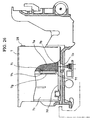
- the printer has to detect the distance between paper or printing medium and the ink emission plane of a print head so that printing is performed correctly at desired positions.
- a lever 301 for adjusting the paper position By using this lever, the paper position is switched between a standard paper position and a thick paper position so as to optimize the paper position for both standard paper and thick paper such as a post card.
- JP-A-02 227 257 discloses an ink jet recorder that detects a remaining amount of ink and communicates corresponding information to a host apparatus. Depending on the communicated information the host apparatus can notify by suitable display means to a user that ink is ended. The user is allowed to replace an ink cartridge or to push an ink end invalid switch.
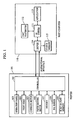
- Figure 1 is a block diagram of a first embodiment of a printing system according to the present invention.
- the printing system includes a printer 101 for printing image data, and a host computer 110 for receiving a command issued by a user and generating image data to be printed (printing information) wherein the printer 101 and the host computer 110 are connected to each other via an interface having the capability of bidirectional communication.
- the interface may be of any type such as that using a cable or a wireless interface using a radio wave or infrared light.
- an ink-jet printer is employed as the printer 101.
- the printer 101 includes: a controller (CPU) 102 responsible for controlling the entire printer; an operation panel 103 including a power on/off switch, an on-line switch for controlling the interface, and a lamp for indicating the status; a print head 104 for firing a droplet of ink at a printing material thereby printing an image thereon; a carriage motor 105 for moving a carriage, on which the print head is installed, in the vertical direction with respect to the print head; a paper feeding motor 106 for feeding, transferring, and pushing out a printing material; a memory 107 for temporarily storing data received from the host computer, and also storing image data (printing information) to be printed, wherein a unit of band size is employed as a storage unit; an ink sensor 108 for detecting the presence or absence of an ink cartridge and also detecting the amount of ink remaining in the ink cartridge; and a built-in font memory 109 for storing characters, pictorial characters, and the
- the ink-jet printer is of the type having the capability of color printing, wherein the color printing is accomplished by a print head 104 having four heads for four colors including black, cyan, magenta, and yellow, these four heads being installed on a carriage.
- the printer receives printing information (bit image information) band by band from the host computer 110, and then prints the received printing information on a printing medium band by band.
- the host computer 110 may transmit the printing information to the printer 101 page by page.
- the host computer may transmit the printing information described in a printer language such as a PDL (Page Description Language) consisting of character and control codes to the printer band by band or page by page.
- a printer language such as a PDL (Page Description Language) consisting of character and control codes
- a CPU (not shown) develops bit map data (printing information) using an OS system 111 and application software 113 for producing documents, tables, and graphical images, in such a manner that the resultant bit map data meets the requirement of resolution needed by a printer driver 114.
- character images consisting of vector information are developed into bit map data (printing information) using a font rasterizer 112.
- the CPU (not shown) generates printing information in the form suitable for a printing operation from the printing information developed into the form of bit map data using the printer driver 114.
- the CPU then adds printer control codes to it and transmits the resultant printing information to the printer.
- the printer driver 114 shows a user various information such as the status regarding the data processing as well as the printer status via a status window 115 at proper times.
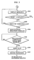
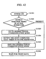
- step S101 shown in Figure 2 the program begins with receiving status information from the printer.
- step S102 if a command is received which indicates that generation of printing information should be started, then in step S103 the program checks an ink cartridge flag. If the ink cartridge flag is 0, that is, all inK cartridges are mounted on the printer, then the program goes to step S104.
- step S104 the program checks a no-ink flag. If the no-ink flag is 0, that is, there is ink in all the ink cartridges, then the program goes to step S105.
- step S105 the program checks a remaining ink flag. If the remaining ink flag is 0, that is, the remaining amount of ink is enough, then the program goes to step S106.
- step S106 printing information is generated by converting image information into a form suitable for printing band by band.
- step S107 the generated printing information is then output to the printer band by band.
- the printing information is in the form of bit map data.
- the printing information may be written in a printer language, such as a PDL, consisting of character and control codes.
- step S103 If it is concluded in step S103 that the ink cartridge flag is 1, that is, some ink cartridge is not mounted on the printer, then the program goes to step S110 and the generation of printing information is temporarily stopped. Then in step S111, a message 1 is displayed.
- the message 1 is displayed in a status window on the display screen as shown in Figure 17.
- the status window contains a message indicating that a particular ink cartridge is not mounted on the printer and also indicating the color of that cartridge.
- the status window also contains "execute” and "stop” buttons. Either button may be selected via input means such as a mouse or a keyboard of the host computer, so that the selected operation will be executed.
- step S112 shown in Figure 2 After mounting an ink cartridge according to the message shown in Figure 17, if the execution button is selected, it is determined in step S112 shown in Figure 2 that replacement of an ink cartridge has been performed, and the program then goes to step S301 shown in Figure 3.
- the stop button is selected in the status window of Figure 17, no ink cartridge is replaced in step S112 of Figure 2, and it is determined in step S113 that a forced aborting command has been issued, and thus the generation of printing information is canceled and the program returns to step S102 and waits until a command advising that generation of printing information should be started is issued again.
- the message 4 is displayed.
- the message 4 is displayed in a status window on the display screen as shown in Figure 22.
- the status window contains a message telling or advising that the printer will start cleaning the print head, and also contains "execute” and "stop” buttons. Either button may be selected via input means such as a mouse or a keyboard of the host computer, so that the selected operation will be executed.
- the stop button it is determined in step S302 of Figure 3 that a forced aborting command has been issued, and thus the generation of printing information is canceled and the program returns to step S102 of Figure 2 and waits until a command telling that generation of printing information should be started is issued again.
- step S302 of Figure 3 the program may return to step S111 of Figure 2 so that the message shown in Figure 17 will be displayed again in the status window.
- step S303 of Figure 3 it is concluded in step S303 of Figure 3 that an "execute" command has been issued, and thus in step S304 a cleaning execution command is sent to the printer.
- the printer sets the cleaning execution flag to 1 and starts the cleaning operation.
- the printer immediately resets the cleaning execution flag to 0.
- the flag may be reset by the printer itself instead of the host computer.
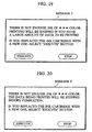
- step S104 of Figure 2 if it is concluded in step S104 of Figure 2 that the no-ink flag is 1 which indicates that there is no ink in an ink cartridge, then the program goes to step S114 at which the generation of printing information is temporarily stopped. Then in step S115, a message 2 is displayed.
- the message 2 is displayed in a status window on the display screen as shown in Figure 18.
- the status window contains a message telling that a particular ink cartridge has no ink in it and also telling the ink color of that cartridge.
- the status window also contains "execute” and "stop” buttons. Either button may be selected via input means such as a mouse or a keyboard of the host computer, so that the selected operation will be executed.
- step S116 of Figure 2 After replacing the corresponding ink cartridge by a new one according to the message shown in Figure 18, if the execution button is selected, it is determined in step S116 of Figure 2 that replacement of the ink cartridge has been performed, and the program then goes to step S301 shown in Figure 3.
- step S117 In the case where the stop button is selected in the status window of Figure 18, replacement of the ink cartridge in step S116 of Figure 2 is not performed, and it is determined in step S117 that an "abort" command has been issued, and generation of printing information is canceled and the program returns to step S102 of Figure 2 at which the program waits until a command telling that generation of printing information should be started is issued again.
- a message 4 is displayed.
- the message 4 is displayed in a status window on the display screen as shown in Figure 22.
- the status window contains a message telling that the printer will start cleaning the print head, and also contains "execute” and "stop” buttons. Either button may be selected via input means such as a mouse or a keyboard of the host computer, so that the selected operation will be executed.
- the stop button it is determined in step S302 of Figure 3 that a forced aborting command has been issued, and thus the generation of printing information is canceled and the program returns to step S102 of Figure 2 and waits until a command telling that generation of printing information should be started is issued again.
- step S302 of Figure 3 the program may return to step S115 of Figure 2 so that the message shown in Figure 18 will be displayed again in the status window.
- step S303 of Figure 3 it is concluded in step S303 of Figure 3 that an "execute" command has been issued, and thus in step S304 a cleaning execution command is sent to the printer.
- the printer sets the cleaning execution flag to 1 and starts the cleaning operation.
- the printer immediately resets the cleaning execution flag to 0.
- the flag may be reset by the printer itself instead of the host computer.
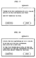
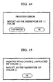
- step S105 of Figure 2 if it is concluded that the remaining ink flag is 1 which indicates that the amount of ink remaining in an ink cartridge is not enough, then the program goes to step S118 at which the generation of printing information is temporarily stopped. Then in step S119, a message 3 is displayed.
- the message 3 is displayed in a status window on the display screen as shown in Figure 19.
- the status window contains a message telling that the amount of remaining ink is not enough and thus printing will be stopped before completion if the amount of data to be printed is too large, and also information of the color of that ink.
- the status window also contains "execute” and "stop” buttons. Either button may be selected via input means such as a mouse or a keyboard of the host computer, so that the selected operation will be executed.
- step S120 of Figure 2 After replacing the corresponding ink cartridge by a new one according to the message shown in Figure 19, if the execution button is selected, it is determined in step S120 of Figure 2 that replacement of the ink cartridge is complete, and the program then goes to step S301 shown in Figure 3. In the case where the stop button is selected in the status window of Figure 19, no ink cartridge is replaced in step S120 of Figure 2, and it is determined in step S121 that a "neglect" command has been issued, and the program goes to step S122 to start generation of printing information again. The program then goes to step S106.
- a message 4 is displayed.
- the message 4 is displayed in a status window on the display screen as shown in Figure 22.
- the status window contains a message telling that the printer will start cleaning the print head, and also contains "execute” and "stop” buttons. Either button may be selected via input means such as a mouse or a keyboard of the host computer, so that the selected operation will be executed.
- the stop button it is determined in step S302 of Figure 3 that a forced aborting command has been issued, and thus the generation of printing information is canceled and the program returns to step S102 of Figure 2 and waits until a command telling that generation of printing information should be started is issued again.
- step S302 of Figure 3 the program may return to step S119 of Figure 2 so that the message shown in Figure 17 will be displayed again in the status window.
- step S304 a cleaning execution command is sent to the printer.
- the printer sets the cleaning execution flag to 1 and starts the cleaning operation.
- the printer immediately resets the cleaning execution flag to 0.
- the flag may be reset by the printer itself instead of the host computer.
- step S108 of Figure 2 The above-described process of checking the flags in the steps S103, S104, and S105 and the succeeding process according to the result of the checking are performed repeatedly until it is concluded in step S108 of Figure 2 that all image data (printing information) has been output. If it is concluded in step S108 that all image data (printing information) has been output, the program goes to step S109. If an "end" command is not issued in step S109, then the program returns to step S109 and waits for another command telling that generation of printing information should be started.
- the host computer can know the printer status regarding the presence of ink cartridges, the lack of ink, and the amount of remaining ink. This provides a great advantage particularly when the printer is installed at a location rather far from the host computer or when the printer is shared by a plurality of computers via a network.
- step S401 shown in Figure 4 the program begins with receiving status information from the printer.
- step S402 if a command is received which indicates that generation of printing information should be started, then in step 5403 an original image is analyzed to determine which ink color should be used.
- the printer driver issues a command to the OS system to convert the printing information generated by application software into image data in a form that matches the resolution of the printer. If the printer has a high resolution such as 360 dpi, the development of image data and the analysis of the colors impose a heavy load on the processing.
- an original image is developed with a low resolution such as 73 dpi first, and the colors of the original image are analyzed, and finally high-resolution development and analysis are performed so as to improve the processing speed. This also reduces the memory capacity requirement.
- step S404 the program checks the ink cartridge flag associated with the color to be used. If the ink cartridge flag associated with the color to be used is 0, that is, an ink cartridge of the color to be used is mounted on the printer, then the program goes to step S405. In step S405, the program checks the no-ink flag associated with the color to be used. If the no-ink flag associated with the color to be used is 0, that is, there is ink in the ink cartridge of the color to be used, then the program goes to step S406. In step S406, the program checks the remaining ink flag associated with the color to be used.
- step S407 printing information is generated by converting image information into a form suitable for printing. Then in step S408 the generated printing information is output to the printer band by band.
- step S404 If it is concluded in step S404 that the ink cartridge flag associated with the color to be used is 1, that is, the ink cartridge of the color to be used is not mounted on the printer, then the program goes to step S411 and the generation of printing information is temporarily stopped. Then in step S412, a message 1 is displayed. As in the case of Embodiment 1, the message 1 is displayed in a status window on the display screen as shown in Figure 17. As shown in Figure 17, the status window contains a message telling that a particular ink cartridge is not mounted on the printer and also telling the color of that cartridge. The status window also contains "execute” and "stop” buttons. Either button may be selected via input means such as a mouse or a keyboard of the host computer, so that the selected operation will be executed.
- step S413 shown in Figure 4 After mounting an ink cartridge according to the message shown in Figure 17, if the execution button is selected, it is determined in step S413 shown in Figure 4 that replacement of an ink cartridge has been performed, and the program then goes to step S301 shown in Figure 3. In the case where the stop button is selected in the status window of Figure 17, no ink cartridge is replaced in step S413 of Figure 4, and it is determined in step S414 that a forced aborting command has been issued, and thus the generation of printing information is canceled and the program returns to step S402 and waits until a command telling that generation of printing information should be started is issued again.
- a message 4 is displayed.
- the message 4 is displayed in a status window on the display screen as shown in Figure 22.
- the status window contains a message telling that the printer will start cleaning the print head, and also contains "execute” and "stop” buttons. Either button may be selected via input means such as a mouse or a keyboard of the host computer, so that the selected operation will be executed.
- step S302 of Figure 3 it is determined in step S302 of Figure 3 that a forced aborting command has been issued, and thus the generation of printing information is canceled and the program returns to step S402 of Figure 4 and waits until a command telling that generation of printing information should be started is issued again.
- the program may return to step S412 of Figure 4 so that the message shown in Figure 17 will be displayed again in the status window. If the "execute" button is selected in the status window of Figure 22, it is concluded in step S303 of Figure 3 that an "execute" command has been issued, and thus in step S304 a cleaning execution command is sent to the printer.
- the flag may be reset by the printer itself instead of the host computer.
- step S405 of Figure 4 if it is concluded in step S405 of Figure 4 that the no-ink flag associated with the color to be used is 1, that is, there is no ink of the color to be used in the ink cartridge, then the program goes to step S415 at which the generation of printing information is temporarily stopped. Then in step S416, a message 2 is displayed. As in the case of Embodiment 1 described above, the message 2 is also displayed in a status window on the display screen as shown in Figure 18. As shown in Figure 18, the status window contains a message telling that a particular ink cartridge has no ink in it and also telling the ink color of that cartridge. The status window also contains "execute” and "stop” buttons.
- Either button may be selected via input means such as a mouse or a keyboard of the host computer, so that the selected operation will be executed.
- the execution button After replacing the corresponding ink cartridge by a new one according to the message shown in Figure 18, if the execution button is selected, it is determined in step S417 of Figure 4 that replacement of the ink cartridge has been performed, and the program then goes to step S301 shown in Figure 3.
- the stop button is selected in the status window of Figure 18, no ink cartridge is replaced in step S417 of Figure 4, and it is determined in step S418 that a forced aborting command has been issued, and thus the generation of printing information is canceled and the program returns to step S402 and waits until a command telling that generation of printing information should be started is issued again.
- a message 4 is displayed.
- the message 4 is also displayed in a status window on the display screen as shown in Figure 22.
- the status window contains a message telling that the printer will start cleaning the print head, and also contains "execute” and "stop” buttons. Either button may be selected via input means such as a mouse or a keyboard of the host computer, so that the selected operation will be executed.
- step S302 it is determined in step S302 that a forced aborting command has been issued, and thus the generation of printing information is canceled and the program returns to step S402 of Figure 4 and waits until a command telling that generation of printing information should be started is issued again.
- the program may return to step S416 of Figure 4 so that the message shown in Figure 18 will be displayed again in the status window. If the "execute" button is selected in the status window of Figure 22, it is concluded in step S303 of Figure 3 that an "execute" command has been issued, and thus in step S304 a cleaning execution command is sent to the printer.
- step S305 On reception of the cleaning execution command, the printer sets the cleaning execution flag to 1 and starts the cleaning operation. When the cleaning operation is completed, the printer immediately resets the cleaning execution flag to 0.
- the flag may be reset by the printer itself instead of the host computer.
- step S406 if it is concluded that the remaining ink flag associated with the color to be used is 1, that is the amount of ink of the color to be used remaining in the ink cartridge is not enough, then the program goes to step S419 at which the generation of printing information is temporarily stopped. Then in step S420, a message 3 is displayed. As in the case of Embodiment 1 described above, the message 3 is also displayed in a status window on the display screen as shown in Figure 19. As shown in Figure 19, the status window contains a message telling that the amount of remaining ink is not enough and thus printing will be stopped before completion if the amount of data to be printed is too large, and also telling the color of that ink. The status window also contains "execute” and "stop” buttons.
- Either button may be selected via input means such as a mouse or a keyboard of the host computer, so that the selected operation will be executed.
- input means such as a mouse or a keyboard of the host computer, so that the selected operation will be executed.
- the execution button After replacing the corresponding ink cartridge by a new one according to the message shown in Figure 19, if the execution button is selected, it is determined in step S421 of Figure 4 that replacement of the ink cartridge is complete, and the program then goes to step S301 shown in Figure 3.
- the stop button is selected in the status window of Figure 19
- no ink cartridge is replaced in step S421 of Figure 4
- step S422 it is determined in step S422 that a "neglect" command has been issued, and the program goes to step 5423 to start generation of printing information again.
- the program then goes to step S407.
- a message 4 is displayed.
- the message 4 is also displayed in a status window on the display screen as shown in Figure 22.
- the status window contains a message telling that the printer will start cleaning the print head, and also contains "execute” and "stop” buttons. Either button may be selected via input means such as a mouse or a keyboard of the host computer, so that the selected operation will be executed.
- step 5302 of Figure 3 it is determined in step 5302 of Figure 3 that a forced aborting command has been issued, and thus the generation of printing information is canceled and the program returns to step S402 of Figure 4 and waits until a command telling that generation of printing information should be started is issued again.
- the program may return to step S420 of Figure 4 so that the message shown in Figure 17 will be displayed again in the status window. If the "execute" button is selected in the status window of Figure 22, it is concluded in step 5303 of Figure 3 that an "execute" command has been issued, and thus in step S304 a cleaning execution command is sent to the printer.
- the flag may be reset by the printer itself instead of the host computer.
- step S409 of Figure 4 If it is concluded in step S409 that all image data (printing information) has been output, the program goes to step S41U. It an "end" command is not issued in step S410, then the program returns to step S402 and waits for another command telling that generation of printing information should be started.
- the host computer can know the printer status regarding the presence of ink cartridges, the lack of ink, and the amount of remaining ink.
- This feature of the present embodiment also provides a great advantage particularly when the printer is installed at a location rather far from the host computer or when the printer is shared by a plurality of computers via a network.
- step S501 snown in Figure 5, the program begins with receiving status information from the printer.
- step S502 if a command is received which indicates that generation of printing information should be started, then in step S503 the program determines the color mode to be used.
- the color mode may be designated by means of selecting operation via the control panel of the printer itself or via a menu of the printer driver displayed on the screen of the host computer.
- the printer When the color mode is selected via the control panel of the printer, the printer itself acquires color mode status information wherein the color mode status is represented by the color mode flag in such a manner that the monochrome printing mode is denoted by a value of 0 in the color mode flag and the color printing mode is denoted by 1.
- step S702 printing information is generated by converting image information into a form suitable for printing band by band. Then in step S703 the generated printing information is output to the printer band by band.
- step S505 of Figure 5 If it is concluded in step S505 of Figure 5 that the ink cartridge flag associated with black ink is 1, that is, the ink cartridge of black ink is not mounted on the printer, then the program goes to step S507 and the generation of printing information is temporarily stopped. Then in step S508, a message 1 is displayed. As in the case of Embodiment 1 described above, the message 1 is also displayed in a status window on the display screen as shown in Figure 17. As shown in Figure 17, the status window contains a message telling that an ink cartridge is not mounted on the printer and also telling the color of that cartridge. The status window also contains "execute” and "stop” buttons. Either button may be selected via input means such as a mouse or a keyboard of the host computer, so that the selected operation will be executed.
- step S509 After mounting an ink cartridge according to the message shown in Figure 17, it the execution button is selected, it is determined in step S509 that replacement of an ink cartridge has been performed, and the program then goes to step S301 shown in Figure 3.
- the stop button In the case where the stop button is selected in the status window of Figure 17, no ink cartridge is replaced in step S509, and it is determined in step S510 that an "abort" command has been issued, and thus the generation of printing information is canceled.
- the program then returns to step S502 and waits for a command indicating that generation of printing information should be started again.
- message 4 is displayed.
- the message 4 is also displayed in a status window on the display screen as shown in Figure 22.
- the status window contains a message telling that the printer will start cleaning the print head, and also contains "execute” and "stop” buttons. Either button may be selected via input means such as a mouse or a keyboard of the host computer, so that the selected operation will be executed.
- step S302 of Figure 3 it is determined in step S302 of Figure 3 that a forced aborting command has been issued, and thus the generation of printing information is canceled and the program returns to step S502 of Figure 5 and waits until a command telling that generation of printing information should be started is issued again.
- the program may return to step S508 of Figure 5 so that the message shown in Figure 15 will be displayed again in the status window. If the "execute" button is selected in the status window of Figure 19, it is concluded in step S303 of Figure 3 that an "execute" command has been issued, and thus in step S304 a cleaning execution command is sent to the printer.
- the flag may be reset by the printer itself instead of the host computer.
- step S506 of Figure 5 if it is concluded in step S506 of Figure 5 that the no-ink flag associated with black ink is 1, that is, there is no ink in the black ink cartridge, then the program goes to step S511 at which the generation of printing information is temporarily stopped. Then in step S511, a message 2 is displayed. As in the case of Embodiment 1 described above, the message 2 is also displayed in a status window on the display screen as shown in Figure 18. As shown in Figure 18, the status window contains a message telling that some ink cartridge has no ink in it and also telling the ink color of that cartridge. The status window also contains "execute” and "stop” buttons.
- Either button may be selected via input means such as a mouse or a keyboard of the host computer, so that the selected operation will be executed.
- the execution button After replacing the corresponding ink cartridge by a new one according to the message shown in Figure 18, if the execution button is selected, it is determined in step S513 of Figure 5 that replacement of the ink cartridge has been performed, and the program then goes to step S301 shown in Figure 3.
- the stop button is selected in the status window of Figure 18, ink cartridge replacement is not performed in step S513, and it is determined in step S514 that an "abort" command has been issued, and thus the generation of printing information is canceled.
- the program then returns to step S502 and waits for a command indicating that generation of printing information should be started again.
- a message 4 is displayed.
- the message 4 is also displayed in a status window on the display screen as shown in Figure 22.
- the status window contains a message telling that the printer will start cleaning the print head, and also contains "execute” and "stop” buttons. Either button may be selected via input means such as a mouse or a keyboard of the host computer, so that the selected operation will be executed.
- step S302 of Figure 3 it is determined in step S302 of Figure 3 that a forced aborting command has been issued, and thus the generation of printing information is canceled and the program returns to step S502 at which the program waits until a command telling that generation of printing information should be started is issued again.
- the program may return to step S512 of Figure 5 so that the message shown in Figure 18 will be displayed again in the status window. If the "execute" button is selected in the status window of Figure 19, it is concluded in step S303 of Figure 3 that an "execute" command has been_issued, and thus in step S304 a cleaning execution command is sent to the printer.
- the flag may be reset by the printer itself instead of the host computer.
- step S701 of Figure 7 if it is concluded that the remaining ink flag associated with black ink is 1, that is the remaining amount of black ink in the ink cartridge is not enough, then the program goes to step S706 at which the generation of printing information is temporarily stopped. Then in step S707, a message 3 is displayed. As in the case of Embodiment 1 described above, the message 3 is also displayed in a status window on the display screen as shown in Figure 19. As shown in Figure 19, the status window contains a message telling that the amount of remaining ink is not enough and thus printing will be stopped before completion if the amount of data to be printed is too large, and also telling the color of that ink. The status window also contains "execute” and "stop” buttons.
- Either button may be selected via input means such as a mouse or a keyboard of the host computer, so that the selected operation will be executed.
- input means such as a mouse or a keyboard of the host computer, so that the selected operation will be executed.
- the execution button After replacing the corresponding ink cartridge by a new one according to the message shown in Figure 19, if the execution button is selected, it is determined in step S708 that replacement of the ink cartridge has been performed, and the program then goes to step S301 shown in Figure 3.
- ink cartridge replacement is not performed in step S708, and it is determined in step S709 that an "abort" command has been issued, and the program goes to step S710 to start generation of printing information again. The program then goes to step S702.
- a message 4 is displayed.
- the message 4 is also displayed in a status window on the display screen as shown in Figure 22.
- the status window contains a message telling that the printer will start cleaning the print head, and also contains "execute” and "stop” buttons. Either button may be selected via input means such as a mouse or a keyboard of the host computer, so that the selected operation will be executed.
- step S302 of Figure 3 it is determined in step S302 of Figure 3 that a forced aborting command has been issued, and thus the generation of printing information is canceled and the program returns to step S502 at which the program waits until a command telling that generation of printing information should be started is issued again.
- the program may return to step S707 of Figure 7 so that the message shown in Figure 19 will be displayed again in the status window. If the "execute" button is selected in the status window of Figure 22, it is concluded in step S303 of Figure 3 that an "execute" command has been issued, and thus in step S304 a cleaning execution command is sent to the printer.
- the flag may be reset by the printer itself instead of the host computer.
- step S704 of Figure 7 the program goes to step S705. If an "end" command is not issued in step S705, then the program returns to step S502 and waits for another command telling that generation of printing information should be started.
- step S504 the current color mode is in the color printing mode
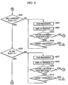
- step S601 of Figure 6 the program checks all the ink cartridge flags associated with individual colors. If the ink cartridge flag is 0, that is, all ink cartridges are mounted on the printer, then the program goes to step S602.
- step S602 the program checks all the no-ink flags associated with individual colors. If all the no-ink flags are 0, that is, there is ink in all the ink cartridges, then the program goes to step S711 of Figure 8. In step S711, the program checks all the remaining ink flags associated with individual colors.
- step S712 printing information is generated by converting image data into a form suitable for printing. Then in step S713 the generated image data (printing information) is output to the printer.
- step S601 If it is concluded in step S601 that the ink cartridge flag associated with a particular color is 1, that is, an ink cartridge of a particular color is not mounted on the printer, then the program goes to step S603 and the generation of printing information is temporarily stopped. Then in step S604, a message 1 is displayed. As in the case of Embodiment 1 described above, the message 1 is also displayed in a status window on the display screen as shown in Figure 17. As shown in Figure 17, the status window contains a message telling that some ink cartridge is not mounted on the printer and also telling the color of that cartridge. The status window also contains "execute” and "stop” buttons. Either button may be selected via input means such as a mouse or a keyboard of the host computer, so that the selected operation will be executed.
- step S605 shown in Figure 6 After mounting an ink cartridge according to the message shown in Figure 17, if the execution button is selected, it is determined in step S605 shown in Figure 6 that replacement of an ink cartridge has been performed, and the program then goes to step S301 shown in Figure 3.
- the stop button is selected in the status window of Figure 17, no ink cartridge is replaced in step S605 of Figure 6, and it is determined in step S606 that a forced aborting command has been issued, and thus the generation of printing information is canceled and the program returns to step S502 of Figure 5 and waits until a command telling that generation of printing information should be started is issued again.
- a message 4 is displayed.
- the message 4 is also displayed in a status window on the display screen as shown in Figure 22.
- the status window contains a message telling that the printer will start cleaning the print head, and also contains "execute” and "stop” buttons. Either button may be selected via input means such as a mouse or a keyboard of the host computer, so that the selected operation will be executed.
- step S302 of Figure 3 it is determined in step S302 of Figure 3 that a forced aborting command has been issued, and thus the generation of printing information is canceled and the program returns to step S502 of Figure 5 and waits until a command telling that generation of printing information should be started is issued again.
- the program may return to step S604 of Figure 6 so that the message shown in Figure 17 will be displayed again in the status window. If the "execute" button is selected in the status window of Figure 22, it is concluded in step S303 of Figure 3 that an "execute" command has been issued, and thus in step S304 a cleaning execution command is sent to the printer.
- the flag may oe reset by the printer itself instead of the host computer.
- step S602 of Figure 6 if it is concluded in step S602 of Figure 6 that the no-ink flag associated with some color is 1, that is, there is no ink in some ink cartridge, then the program goes to step S607 at which the generation of printing information is temporarily stopped. Then in step S608, a message 2 is displayed. As in the case of Embodiment 1 described above, the message 2 is also displayed in a status window on the display screen as shown in Figure 18. As shown in Figure 18, the status window contains a message telling that a particular ink cartridge has no ink in it and also telling the ink color of that cartridge. The status window also contains "execute” and "stop” buttons.
- Either button may be selected via input means such as a mouse or a keyboard of the host computer, so that the selected operation will be executed.
- the execution button After mounting an ink cartridge according to the message shown in Figure 18, if the execution button is selected, it is determined in step S609 that replacement of an ink cartridge has been performed, and the program then goes to step S301 shown in Figure 3.
- the stop button is selected in the status window of Figure 18, ink cartridge replacement is not performed in step S609, and it is determined in step S610 that a forced aborting command has been issued, and thus the generation of printing information is canceled and the program returns to step S502 of Figure 5 and waits until a command telling that generation of printing information should be started is issued again.
- a message 4 is displayed.
- the message 4 is also displayed in a status window on the display screen as shown in Figure 22.
- the status window contains a message telling that the printer will start cleaning the print head, and also contains "execute” and "stop” buttons. Either button may be selected via input means such as a mouse or a keyboard of the host computer, so that the selected operation will be executed.
- step S302 of Figure 3 it is determined in step S302 of Figure 3 that a forced aborting command has been issued, and thus the generation of printing information is canceled and the program returns to step S502 of Figure 5 and waits until a command telling that generation of printing information should be started is issued again.
- the program may return to step S608 of Figure 6 so that the message shown in Figure 18 will be displayed again in the status window.
- step S303 If the "execute" button is selected in the status window of Figure 22, it is concluded in step S303 ot Figure 3 that an "execute" command has been issued, and thus in step S304 a cleaning execution command is sent to the printer.
- the printer On reception of the cleaning execution command, the printer sets the cleaning execution flag to 1 and starts the cleaning operation. When the cleaning operation is completed, the printer immediately resets the cleaning execution flag to 0.
- the flag may be reset by the printer itself instead of the host computer.
- step S711 of Figure 8 if it is concluded that a particular remaining ink flag is 1, that is the remaining amount of ink in a particular ink cartridge is not enough, then the program goes to step S716 at which the generation of printing information is temporarily stopped. Then in step S717, a message 3 is displayed. As in the case of Embodiment 1 described above, the message 3 is also displayed in a status window on the display screen as shown in Figure 19. As shown in Figure 19, the status window contains a message telling that the remaining amount of ink is not enough and tnus printing will be stopped before completion if the amount of data to be printed is too large, and also telling the color of that ink. The status window also contains "execute” and "stop” buttons.
- Either button may be selected via input means such as a mouse or a keyboard of the host computer, so that the selected operation will be executed.
- input means such as a mouse or a keyboard of the host computer, so that the selected operation will be executed.
- the execution button After replacing the corresponding ink cartridge by a new one according to the message shown in Figure 19, if the execution button is selected, it is determined in step S718 of Figure 8 that replacement of the ink cartridge is complete, and the program then goes to step S301 shown in Figure 3.
- ink cartridge replacement is not performed in step S718, and it is determined in step S719 that an "abort" command has been issued, and the program goes to step S720 to start generation of printing information again. The program then goes to step S712.
- a message 4 is displayed.
- the message 4 is also displayed in a status window on the display screen as shown in Figure 22.
- the status window contains a message telling that the printer will start cleaning the print head, and also contains "execute” and "stop” buttons. Either button may be selected via input means such as a mouse or a keyboard of the host computer, so that the selected operation will be executed.
- step S302 of Figure 3 it is determined in step S302 of Figure 3 that a forced aborting command has been issued, and thus the generation of printing information is canceled and the program returns to step S502 of Figure 5 and waits until a command telling that generation of printing information should be started is issued again.
- the program may return to step S717 of Figure 8 so that the message shown in Figure 19 will be displayed again in the status window. If the "execute" button is selected in the status window of Figure 22, it is concluded in step S303 of Figure 3 that an "execute" command has been issued, and thus in step S304 a cleaning execution command is sent to the printer.
- the flag may be reset by the printer itself instead of the host computer.
- step S714 of Figure 8 The above-described process of checking the flags in steps S601 and S602 of Figure 6 and step S711 of Figure 8 and the succeeding process according to the result of the checking are performed repeatedly until it is concluded in step S714 of Figure 8 that all image data (printing information) has been output. If it is concluded in step S714 that all image data (printing information) has been output, the program goes to step S715. If an "end" command is not issued in step S715, then the program returns to step - S502 of Figure 5 and waits for another command telling that generation of printing information should be started.
- the host computer can know the printer status regarding the presence of ink cartridges, the lack of ink, and the amount of remaining ink.
- This feature of the present embodiment also provides a great advantage particularly when the printer is installed at a location rather far from the host computer or when the printer is shared by a plurality of computers via a network.
- the detection of the ink cartridge flags, no-ink flags, and remaining ink flags is performed depending on the designated color mode, and thus the detection time is reduced when operating in the monochrome printing mode in which only black ink is used, which results in an improvement in the printing speed. This also prevents the printing operation from being unnecessarily stopped by status information regarding an ink color which is not used. Furthermore, in this embodiment it is not required to determine which color should be used in printing, and therefore the processing load associated with handling of image data is reduced.
- step S501 shown in Figure 5 the program begins with receiving status information from the printer.
- step S502 if a command is received which indicates that generation of printing information should be started, then in step S503 the program determines the color mode to be used.
- the color mode may be designated by means of selecting operation via the control panel of the printer itself or via a menu of the printer driver displayed on the screen of the host computer.
- the printer When the color mode is selected via the control panel of the printer, the printer itself acquires color mode status information wherein the color mode status is represented by the color mode flag in such a manner that the monochrome printing mode is denoted by a value of 0 in the color mode flag and the color printing mode is denoted by 1.
- step S504. If it is determined that the current color mode is in the monochrome printing mode, then the program goes to step S505. In step S505, only the ink cartridge flag associated with black ink is examined. If the ink cartridge flag associated with black ink is 0, that is, an ink cartridge of black ink is mounted on the printer, then the program goes to step 5506. In step S506, only the no-ink flag associated with black ink is examined. If the no-ink flag associated with black ink is 0, that is, there is ink in the black ink cartridge, then the program goes to step S801. In step S801, only the remaining ink flag associated with black ink is examined.
- step S802 printing information is generated by converting image data into a form suitable for printing. Then in step S803 the generated image data (printing information) is output to the printer.
- step S505 of Figure 5 If it is concluded in step S505 of Figure 5 that the ink cartridge flag associated with black ink is 1, that is, the ink cartridge of black ink is not mounted on the printer, then the program goes to step S507 and the generation of printing information is temporarily stopped. Then in step S508, a message 1 is displayed. As in the case of Embodiment 1 described above, the message 1 is also displayed in a status window on the display screen as shown in Figure 17. As shown in Figure 17, the status window contains a message telling that a particular ink cartridge is not mounted on the printer and also telling the color of that cartridge. The status window also contains "execute” and "stop” buttons. Either button may be selected via input means such as a mouse or a keyboard of the host computer, so that the selected operation will be executed.
- step S509 shown in Figure 5 After mounting an ink cartridge according to the message shown in Figure 17, if the execution button is selected, it is determined in step S509 shown in Figure 5 that replacement of an ink cartridge has been performed, and the program then goes to step S301 shown in Figure 3. in the case wnere the stop button is selected in the status window of Figure 17, ink cartridge replacement is not performed in step S509 of Figure 5, and it is determined in step S510 that an "abort" command has been issued, and the generation of printing information is canceled. In this case, the program returns to step S502 in which the program waits for a command telling that generation of printing information should be started.
- a message 4 is displayed.
- the message 4 is also displayed in a status window on the display screen as shown in Figure 22.
- the status window contains a message telling that the printer will start cleaning the print head, and also contains "execute” and "stop” buttons. Either button may be selected via input means such as a mouse or a keyboard of the host computer, so that the selected operation will be executed.
- step S302 of Figure 3 it is determined in step S302 of Figure 3 that a forced aborting command has been issued, and thus the generation of printing information is canceled and the program returns to step S502 at which the program waits until a command telling that generation of printing information should be started is issued again.
- the program may return to step S508 of Figure 5 so that the message shown in Figure 17 will be displayed again in the status window. If the "execute" button is selected in the status window of Figure 22, it is concluded in step S303 of Figure 3 that an "execute" command has been issued, and thus in step S304 a cleaning execution command is sent to the printer.
- step S506 of Figure 5 if it is concluded in step S506 of Figure 5 that the no-ink flag associated with black ink is 1, that is, there is no ink in the black ink cartridge, then the program goes to step S511 at which the generation of printing information is temporarily stopped. Then in step S511, a message 2 is displayed. As in the case of Embodiment 1 described above, the message 2 is also displayed in a status window on the display screen as shown in Figure 18. As shown in Figure 18, the status window contains a message telling that a particular ink cartridge has no ink in it and also telling the ink color of that cartridge. The status window also contains "execute” and "stop” buttons.
- Either button may be selected via input means such as a mouse or a keyboard of the host computer, so that the selected operation will be executed.
- the execution button After replacing the corresponding ink cartridge by a new one according to the message shown in Figure 18, if the execution button is selected, it is determined in step S513 of Figure 5 that replacement of the ink cartridge has been performed, and the program then goes to step S301 shown in Figure 3.
- the stop button is selected in the status window of Figure 18, no ink cartridge is replaced in step S513 of Figure 5, and it is determined in step S514 that a forced aborting command has been issued, and thus the generation of printing information is canceled and the program returns to step S502 and waits until a command telling that generation of printing information should be started is issued again.
- a message 4 is displayed.
- the message 4 is also displayed in a status window on the display screen as shown in Figure 22.
- the status window contains a message telling that the printer will start cleaning the print head, and also contains "execute” and "stop” buttons. Either button may be selected via input means such as a mouse or a keyboard of the host computer, so that the selected operation will be executed.
- step S302 of Figure 3 it is determined in step S302 of Figure 3 that a forced aborting command has been issued, and thus the generation of printing information is canceled and the program returns to step S502 of Figure 5 and waits until a command telling that generation of printing information should be started is issued again.
- the program may return to step S512 of Figure 5 so that the message shown in Figure 18 will be displayed again in the status window. If the "execute" button is selected in the status window of Figure 22, it is concluded in step S303 of Figure 3 that an "execute" command has been issued, and thus in step S304 a cleaning execution command is sent to the printer.
- the flag may be reset by the printer itself instead of the host computer.
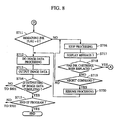
- step S801 of Figure 9 if it is concluded that the remaining ink flag associated with black ink is 1, that is the remaining amount of black ink in the ink cartridge is not enough, then the program goes to step S806 at which the generation of printing information is temporarily stopped. Then in step S807, a message 33 is displayed.
- the message 33 is displayed in a status window on the display screen as shown in Figure 21.
- the status window contains a message telling that the amount of remaining ink is not enough and thus printing will be stopped before completion if the amount of data to be printed is too large, and also telling the color of that ink.
- the status window also contains "execute”, “alternative color” and "stop” buttons.
- Either button may be selected via input means such as a mouse or a keyboard of the host computer, so that the selected operation will be executed.
- the execution button After replacing the corresponding ink cartridge by a new one according to the message shown in Figure 21, if the execution button is selected, it is determined in step S808 of Figure 9 that replacement of the ink cartridge is complete, and the program then goes to step S301 shown in Figure 3.
- the stop button is selected in the status window of Figure 21
- ink cartridge replacement is not performed in step S808 of Figure 9.
- step S810 it is determined that a "neglect" command has been issued.
- the program goes to step S811 to start generation of printing information again.
- step S802 Even in the case where only a small amount of ink remains, printing may be performed on a few further pages if the image to be printed has a low dot density as in the case of a usual document, almost all portions of which are in the form of characters. Therefore, the generation of printing information is not forced to be canceled in this case and the user can select whether the ink cartridge is immediately replaced by a new one or printing is performed without replacement of the ink cartridge.
- a message 4 is displayed.
- the message 4 is also displayed in a status window on the display screen as shown in Figure 22.
- the status window contains a message telling that the printer will start cleaning the print head, and also contains "execute” and "stop” buttons. Either button may be selected via input means such as a mouse or a keyboard of the host computer, so that the selected operation will be executed.
- step S302 of Figure 3 it is determined in step S302 of Figure 3 that a forced aborting command has been issued, and thus the generation of printing information is canceled and the program returns to step S502 of Figure 5 and waits until a command telling that generation of printing information should be started is issued again.
- the program may return to step S807 of Figure 9 so that the message shown in Figure 21 will be displayed again in the status window. If the "execute" button is selected in the status window of Figure 22, it is concluded in step S303 of Figure 3 that an "execute" command has been issued, and thus in step S304 a cleaning execution command is sent to the printer.
- the flag may be reset by the printer itself instead of the host computer.
- step S808 of Figure 9 Ink cartridge replacement in step S808 of Figure 9 is not performed and it is determined in step S809 that use of an alternative color is requested.
- the program goes to step S901 of Figure 11 in which a message 5 is displayed.
- the message 5 is displayed in a window on the display screen as shown in Figure 23.
- the window contains color selection buttons for selecting an alternative color from the group including cyan, magenta, yellow, and gray which is a mixture of the above three colors.
- the window also contains "execute” and "stop” buttons as well as an instruction message.
- Either button may be selected via input means such as a mouse or a keyboard of the host computer, so that the selected operation will be executed. If “gray” (mixture of three colors) is selected, printing is performed with a color similar to black which is produced by properly mixing cyan, magenta, and yellow.
- step S905 of Figure 11 it is determined in step S905 of Figure 11 that a forced aborting command has been issued, and thus the program goes to step S802 of Figure 9.
- the program may return to step S807 so that the immediately previous message will be displayed again in the status window.
- step S903 the ink cartridge flag, no-ink flag, and the remaining ink flag associated with the designated alternative color are examined. If all these flags are 0, that is, the ink of the designated color is available, then the program goes to step S907 in which the printing mode is switched to an alternative color mode. Then in step S906, the generation of printing information is started again. The program then goes to step S802 of Figure 9.
- the image data (printing information) processing in step S803 is performed in such a manner that monochrome (black) data is replaced by alternative color data and the resultant image data (printing information) is output.
- step S903 of Figure 11 if at least of one of flags including the ink cartridge flag, no-ink flag, and remaining ink flag associated with the designated alternative color is 1, the designated color is not available. In this case, a message 6 is displayed in step S904.
- the message 6 is displayed in a status window on the display screen as shown in Figure 24.
- the status window contains a message telling that the color designated as the alternative color is not available and also contains "execute” and "stop” buttons. Either button may be selected via input means such as a mouse or a keyboard of the host computer, so that the selected operation will be executed.
- step S905 of Figure 11 it is determined in step S905 of Figure 11 that a forced aborting command has been issued, and thus the program goes to step S802 of Figure 9. If the "execute" button is selected, the program returns to step S901 of Figure-11 in which the message 5 is displayed again. Alternatively, in the case where the "stop" button is selected in the window of Figure 24, the program may return to step S807 of Figure 9 so that the message shown in Figure 21 will be displayed again in the status window.
- detection of the ink cartridge flag, no-ink flag, and remaining ink flag is performed only for those associated with the designated alternative color, during the following process steps until outputting of all image data (printing information) is completed.
- step S804 If it is concluded in step S804 that all image data (printing information) has been output, the program goes to step S805. If an "end" command is not issued in step S805, then the program returns to step S502 of Figure 5 and walls for another command telling that generation of printing information should be started.
- step S601 of Figure 6 the program checks all the ink cartridge flags associated with individual colors. If the ink cartridge flag is 0, that is, all ink cartridges are mounted on the printer, then the program goes to step S602. In step S602, the program checks all the no-ink flags associated with individual colors. If all the no-ink flags are 0, that is, there is ink in all ink cartridges, then the program goes to step S812 of Figure 9. In step S812, the program checks all the remaining ink flags associated with individual colors.
- step S813 printing information is generated by converting image data into a form suitable for printing. Then in step S814 the generated image data (printing information) is output to the printer.
- step S601 of Figure 6 If it is concluded in step S601 of Figure 6 that a particular-ink cartridge flag is 1, that is, an ink cartridge of a particular color is not mounted on the printer, then the program goes to step S603 and the generation of printing information is temporarily stopped. Then in step S604, a message 1 is displayed. As in the case of Embodiment 1 described above, the message 1 is also displayed in a status window on the display screen as shown in Figure 17. As shown in Figure 17, the status window contains a message telling that a particular ink cartridge is not mounted on the printer and also telling the color of that cartridge. The status window also contains "execute” and "stop” buttons. Either button may be selected via input means such as a mouse or a keyboard of the host computer, so that the selected operation will be executed.
- step S605 of Figure 6 After mounting an ink cartridge according to the message shown in Figure 17, if the "execute" button is selected, it is determined in step S605 of Figure 6 that replacement of an ink cartridge has been performed, and thus the program goes to step S301 of Figure 3. In the case where the stop button is selected in the status window of Figure 17, ink cartridge replacement is not performed in step S605 of Figure 6, and it is determined in step S606 that a forced aborting command has been issued, and thus the generation of printing information is canceled and the program returns to step S502 in which the program waits until a command telling that generation of printing information should be started is issued again.
- a message 4 is displayed.
- the message 4 is also displayed in a status window on the display screen as shown in Figure 22.
- the status window contains a message telling that the printer will start cleaning the print head, and also contains "execute” and "stop” buttons. Either button may be selected via input means such as a mouse or a keyboard of the host computer, so that the selected operation will be executed.
- step S302 of Figure 3 it is determined in step S302 of Figure 3 that a forced aborting command has been issued, and thus the generation of printing information is canceled and the program returns to step S502 of Figure 5 and waits until a command telling that generation of printing information should be started is issued again.
- the program may return to step S604 of Figure 6 so that the message shown in Figure 17 will be displayed again in the status window. If the "execute" button is selected in the status window of Figure 22, it is concluded in step S303 of Figure 3 that an "execute" command has been issued, and thus in step S304 a cleaning execution command is sent to the printer.
- step S305 On reception of the cleaning execution command, the printer sets the cleaning execution flag to 1 and starts the cleaning operation. when the cleaning operation is completed, the printer immediately resets the cleaning execution flag to 0.
- the flag may be reset by the printer itself instead of the host computer.
- step S602 of Figure 6 if it is concluded in step S602 of Figure 6 that the no-ink flag associated with.a particular color is 1, that is, there is no ink in a particular ink cartridge, then the program goes to step S607 at which the generation of printing information is temporarily stopped. Then in step S608, a message 2 is displayed. As in the case of Embodiment 1 described above, the message 2 is also displayed in a status window on the display screen as shown in Figure 18. As shown in Figure 18, the status window contains a message telling that a particular ink cartridge has no ink in it and also telling the ink color of that cartridge. The status window also contains "execute” and "stop” buttons.
- Either button may be selected via input means such as a mouse or a keyboard of the host computer, so that the selected operation will be executed.
- input means such as a mouse or a keyboard of the host computer, so that the selected operation will be executed.
- step S609 replacement of the ink cartridge has been performed, and thus the program goes to step S301 shown in Figure 3.
- step S606 ink cartridge replacement is not performed in step S606, and it is determined in step S610 that a forced aborting command has been issued, and thus the generation of printing information is canceled and the program returns to step S502 of Figure 5 in which the program waits until a command telling that generation of printing information should be started is issued again.
- a message 4 is displayed.
- the message 4 is also displayed in a status window on the display screen as shown in Figure 22.
- the status window contains a message telling that the printer will start cleaning the print head, and also contains "execute” and "stop” buttons. Either button may be selected via input means such as a mouse or a keyboard of the host computer, so that the selected operation will be executed.
- step S302 of Figure 3 it is determined in step S302 of Figure 3 that a forced aborting command has been issued, and thus the generation of printing information is canceled and the program returns to step S502 of Figure 5 and waits until a command telling that generation of printing information should be started is issued again.
- the program may return to step S608 of Figure 6 so that the message shown in Figure 18 will be displayed again in the status window. If the "execute" button is selected in the status window of Figure 22, it is concluded in step S303 of Figure 3 that an "execute" command has been issued, and thus in step S304 a cleaning execution command is sent to the printer.
- the flag may be reset by the printer itself instead of the host computer.
- step S812 of Figure 10 if it is concluded that a particular remaining ink flag is 1, that is, the remaining amount of ink in a particular color ink cartridge is not enough, then the program goes to step S817 at which the generation of printing information is temporarily stopped. Then in step S818, a message 3 is displayed. As in the case of Embodiment 1 described above, the message 3 is also displayed in a status window on the display screen as shown in Figure 19.
- the status window contains a message telling that the remaining amount of ink is not enough and thus printing will be stopped before completion if the amount of data to be printed is too large, and also telling the color of that ink.
- the status window also contains "execute” and "stop” buttons.
- Either button may be selected via input means such as a mouse or a keyboard of the host computer, so that the selected operation will be executed.
- input means such as a mouse or a keyboard of the host computer, so that the selected operation will be executed.
- the execution button After replacing the corresponding ink cartridge by a new one according to the message shown in Figure 19, if the execution button is selected, it is determined in step S819 of Figure 10 that replacement of the ink cartridge is complete, and the program then goes to step S301 shown in Figure 3.
- the stop button is selected in the status window of Figure 19
- no ink cartridge is replaced in step S819 of- Figure 10
- it is determined in step S820 that an "abort" command has been issued and the program goes to step S821 to start generation of printing information again.
- the program then goes to step S813.
- a message 4 is displayed.
- the message 4 is also displayed in a status window on the display screen as shown in Figure 22.
- the status window contains a message telling that the printer will start cleaning the print head, and also contains "execute” and "stop” buttons. Either button may be selected via input means such as a mouse or a keyboard of the host computer, so that the selected operation will be executed.
- step S302 of Figure 3 it is determined in step S302 of Figure 3 that a forced aborting command has been issued, and thus the generation of printing information is canceled and the program returns to step S502 of Figure 5 and waits until a command telling that generation of printing information should be started is issued again.
- the program may return to step S808 of Figure 9 so that the message shown in Figure 19 will be displayed again in the status window. If the "execute" button is selected in the status window of Figure 22, it is concluded in step S303 of Figure 3 that an "execute" command has been issued, and thus in step S304 a cleaning execution command is sent to the printer.
- the flag may be reset by the printer itself instead of the host computer.
- step S815 of Figure 10 all image data (printing information) has been output. If it is concluded in step S815 that all image data (printing information) has been output, the program goes to step S816. If an "end" command is not issued in step S816, then the program returns to step S502 of Figure 5 and waits for another command telling that generation of printing information should be started.
- the host computer can know the printer status regarding the presence of ink cartridges, the lack of ink, and the amount of remaining ink.
- This feature of the present embodiment also provides a great advantage particularly when the printer is installed at a location rather far from the host computer or when the printer is shared by a plurality of computers via a network.
- the detection of the ink cartridge flags, no-ink flags, and remaining ink flags is performed depending on the designated color mode, and thus the detection time is reduced when operating in the monochrome printing mode in which only black ink is used, which results in an improvement in the printing speed.
- This also prevents the printing operation from being unnecessarily stopped by status information regarding an ink color which is not used.
- it is not required to determine which color should be used in printing, and therefore the processing load associated with handling of image data is reduced.
- even if the remaining amount of black ink becomes very small during a printing operation in the monochrome printing mode it is possible to continue the printing operation by designating an alternative color without replacing the ink cartridge with a new one. This provides an advantage particularly when the printing operation has to be completed without a delay.
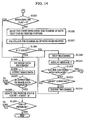
- step S1001 shown in Figure 12 the program begins with receiving status information from the printer.
- step S1002 if a command is received which indicates that generation of printing information should be started, the program goes to step S1003.
- step S1003 the program checks ink cartridge flags. If the ink cartridge flags are 0, that is, all ink cartridges are mounted on the printer, then the program goes to step S1004.
- step S1004 the program checks no-ink flags. If all the no-ink flags are 0, that is, there is ink in all ink cartridges, then the program goes to step S1101 of Figure 13.
- step S1101 the program checks remaining ink flags. If the remaining ink flags are 0, that is, the remaining amount of ink is enough, then the program goes to step S1105.
- step S1105 printing information is generated by converting image data into a form suitable for printing. Then in step S1106 the generated image data (printing information) is output to the printer.
- step S1003 of Figure 12 If it is concluded in step S1003 of Figure 12 that a particular ink cartridge flag is 1, that is, a particular ink cartridge is not mounted on the printer, then the program goes to step S1005 and the generation of printing information is temporarily stopped. Then in step S1006, a message 1 is displayed. As in the case of Embodiment 1 described above, the message 1 is also displayed in a status window on the display screen as shown in Figure 17. As shown in Figure 17, the status window contains a message telling that a particular ink cartridge is not mounted on the printer and also telling the color of that cartridge. The status window also contains "execute” and "stop” buttons. Either button may be selected via input means such as a mouse or a keyboard of the host computer, so that the selected operation will be executed.
- step S1007 shown in Figure 12 After mounting an ink cartridge according to the message shown in Figure 17, if the execution button is selected, it is determined in step S1007 shown in Figure 12 that replacement of an ink cartridge has been performed, and the program then goes to step S301 shown in Figure 3.
- step S1008 In the case where the stop button is selected in the status window of Figure 17, ink cartridge replacement in step S1007 of Figure 12 is not performed, and it is determined in step S1008 that a forced aborting command has been issued, and thus the generation of printing information is canceled and the program returns to step S1002 at which the program waits until a command telling that generation of printing information should be started is issued again.
- a message 4 is displayed.
- the message 4 is also displayed in a status window on the display screen as shown in Figure 22.
- the status window contains a message telling that the printer will start cleaning the print head, and also contains "execute” and "stop” buttons. Either button may be selected via input means such as a mouse or a keyboard of the host computer, so that the selected operation will be executed.
- step S302 of Figure 3 it is determined in step S302 of Figure 3 that a forced aborting command has been issued, and thus the generation of printing information is canceled and the program returns to step S1002 of Figure 12 and waits until a command telling that generation of printing information should be started is issued again.
- the program may return to step S1006 of Figure 12 so that the message shown in Figure 17 will be displayed again in the status window. If the "execute" button is selected in the status window of Figure 22, it is concluded in step S303 of Figure 3 that an "execute" command has been issued, and thus in step S304 a cleaning execution command is sent to the printer.
- step S1004 of Figure 12 if it is concluded in step S1004 of Figure 12 that the no-ink flag is 1 which indicates that there is no ink in an ink cartridge, then the program goes to step S1009 at which the generation or printing information is temporarily stopped. Then in step S1010, a message 2 is displayed. As in the case of Embodiment 1 described above, the message 2 is also displayed in a status window on the display screen as shown in Figure 18. As shown in Figure 18, the status window contains a message telling that a particular ink cartridge has no ink in it and also telling the ink color of that cartridge. The status window also contains "execute” and "stop” buttons. Either button may be selected via input means such as a mouse or a keyboard of the host computer, so that the selected operation will be executed.
- step S1011 of Figure 12 After replacing the corresponding ink cartridge with a new one according to the message shown in Figure 18, if the execution button is selected, it is determined in step S1011 of Figure 12 that replacement of the ink cartridge has been performed, and the program then goes to step S301 shown in Figure 3.
- the stop button is selected in the status window of Figure 18, no ink cartridge is replaced in step S1011 of Figure 12, and it is determined in step S1012 that a forced aborting command has been issued, and thus the generation of printing information is canceled and the program returns to step S1002 and waits until a command telling that generation of printing information should be started is issued again.
- a message 4 is displayed.
- the message 4 is also displayed in a status window on the display screen as shown in Figure 22.
- the status window contains a message telling that the printer will start cleaning the print head, and also contains "execute” and "stop” buttons. Either button may be selected via input means such as a mouse or a keyboard of the host computer, so that the selected operation will be executed.
- step S302 of Figure 3 it is determined in step S302 of Figure 3 that a forced aborting command has been issued, and thus the generation of printing information is canceled and the program returns to step S1002 of Figure 12 and waits until a command telling that generation of printing information should be started is issued again.
- the program may return to step S1010 of Figure 12 so that the message shown in Figure 18 will be displayed again in the status window. If the "execute" button is selected in the status window of Figure 22, it is concluded in step S303 of Figure 3 that an "execute" command has been issued, and thus in step S304 a cleaning execution command is sent to the printer.
- step S1101 of Figure 11 if it is concluded that a particular remaining ink flag is 1, that is, the remaining amount of ink in a particular color ink cartridge is not enough, then the program goes to step S1102 to read the value of "Count" representing the number of dots that can be printed further.
- the maximum possible number of dots that can be printed after the remaining ink flag in the printer becomes 1 is estimated, and this estimated value is used as the initial value of "Count".
- This value is previously set in a counter disposed in the printer.
- the printer counts the number of dots that are printed after the remaining ink flag became 1, and the value of "Count” is decremented on the basis of the above counted value.
- the program then goes to step S1103 and determines the number (D) of dots to be printed. Then comparison is made in step S1104. If D ⁇ Count, the program goes to step S1105 to continue the processing of the image data (printing information).
- step S1109 the program goes to step S1109 at which the generation of printing information is temporarily stopped.
- step S1110 a message 3' is displayed.
- the message 3' is displayed in a status window on the display screen as shown in Figure 20.
- the status window contains a message telling that the remaining amount of ink is not enough and thus printing will be stopped before completion and also telling the color of that ink.
- the status window also contains "execute” and "stop” buttons. Either button may be selected via input means such as a mouse or a keyboard of the host computer, so that the selected operation will be executed.
- step S1111 of Figure 13 After replacing the corresponding ink cartridge with a new one according to the message shown in Figure 20, if the execution button is selected, it is determined in step S1111 of Figure 13 that replacement of the ink cartridge is complete, and the program then goes to step S301 shown in Figure 3.
- the stop button is selected in the status window of Figure 20
- no ink cartridge is replaced in step S1111 of Figure 13, and it is determined in step S1112 that a "neglect" command has been issued, and the program goes to step S1113 to start generation or printing information again.
- the program then goes to step S1105. In this case, the generation of printing information is not canceled.
- a message 4 is displayed.
- the message 4 is also displayed in a status window on the display screen as shown in Figure 22.
- the status window contains a message telling that the printer will start cleaning the print head, and also contains "execute” and "stop” buttons. Either button may be selected via input means such as a mouse or a keyboard of the host computer, so that the selected operation will be executed.
- step S302 of Figure 3 it is determined in step S302 of Figure 3 that a forced aborting command has been issued, and thus the generation of printing information is canceled and the program returns to step S1002 of Figure 12 and waits until a command telling that generation of printing information should be started is issued again.
- the program may return to step S1110 of Figure 13 so that the message shown in Figure 20 will be displayed again in the status window. If the "execute" button is selected in the status window of Figure 22, it is concluded in step S303 of Figure 3 that an "execute" command has been issued, and thus in step S304 a cleaning execution command is sent to the printer.
- the flag may be reset by the printer itself instead of the host computer.
- step S1107 of Figure 13 The above-described process of checking the flags in steps S1003 and S1004 of Figure 12 and step S1101 of Figure 13 and the succeeding process according to the result of the checking are performed repeatedly until it is concluded in step S1107 of Figure 13 that all image data (printing information) has been output. If it is concluded in step S1107 that all image data (printing information) has been output, the program goes to step S1108. If an "end" command is not issued in step S1108, then the program returns to step S1002 of Figure 12 and waits for another command telling that generation of printing information should be started.
- the host computer can know the printer status regarding the presence of ink cartridges, the lack of ink, and the amount of remaining ink.
- This feature of the present embodiment also provides a great advantage particularly when the printer is installed at a location rather far from the host computer or when the printer is shared by a plurality of computers via a network.
- step S1001 shown in Figure 12 the program begins with receiving status information from the printer.
- step S1002 if a command is received which indicates that generation of printing information should be started the program goes to step S1003.
- step S1003 the program checks ink cartridge flags. If the ink cartridge flag is 0, that is, all ink cartridges are mounted on the printer, then the program goes to step S1004.
- step S1004 the program checks no-ink flags. If all the no-ink flags are 0, that is, there is ink in all ink cartridges, then the program goes to step S1201 of Figure 14.
- step S1201 the program checks a remaining ink flag. If the remaining ink flag is 0, that is, the remaining amount of ink is enough, then the program goes to step S1205.
- step S1205 printing information is generated by converting image information into a form suitable for printing. Then in step S1206 the generated printing information is output to the printer band by band.
- step S1003 of Figure 12 If it is concluded in step S1003 of Figure 12 that a particular ink cartridge flag is 1, that is, a particular ink cartridge is not mounted on the printer, then the program goes to step S1005 and the generation of printing information is temporarily stopped. Then in step S1006, a message 1 is displayed. As in the case of Embodiment 1 described above, the message 1 is also displayed in a status window on the display screen as shown in Figure 17. As shown in Figure 17, the status window contains a message telling that a particular ink cartridge is not mounted on the printer and also telling the color of that cartridge. The status window also contains "execute” and "stop” buttons. Either button may be selected via input means such as a mouse or a keyboard of the host computer, so that the selected operation will be executed.
- step S1007 shown in Figure 12 After mounting an ink cartridge according to the message shown in Figure 17, if the execution button is selected, it is determined in step S1007 shown in Figure 12 that replacement of an ink cartridge has been performed, and the program then goes to step S301 shown in Figure 3.
- step S1008 In the case where the stop button is selected in the status window of Figure 17, ink cartridge replacement in step S1007 of Figure 12 is not performed, and it is determined in step S1008 that a forced aborting command has been issued, and thus the generation of printing information is canceled and the program returns to step S1002 at which the program waits until a command telling that generation of printing information should be started is issued again.
- a message 4 is displayed.
- the message 4 is also displayed in a status window on the display screen as shown in Figure 22.
- the status window contains a message telling that the printer will start cleaning the print head, and also contains "execute” and "stop” buttons. Either button may be selected via input means such as a mouse or a keyboard of the host computer, so that the selected operation will be executed.
- step S302 of Figure 3 it is determined in step S302 of Figure 3 that a forced aborting command has been issued, and thus the generation of printing information is canceled and the program returns to step S1002 of Figure 12 and waits until a command telling that generation of printing information should be started is issued again.
- the program may return to step S1006 of Figure 12 so that the message shown in Figure 17 will be displayed again in the status window. If the "execute" button is selected in the status window of Figure 22, it is concluded in step S303 of Figure 3 that an "execute" command has been issued, and thus in step S304 a cleaning execution command is sent to the printer.
- step S1004 of Figure 12 if it is concluded in step S1004 of Figure 12 that the no-ink flag is 1 which indicates that there is no ink in an ink cartridge, then the program goes to step 51009 at which the generation of printing information is temporarily stopped. Then in step S1010, a message 2 is displayed. As in the case of Embodiment 1 described above, the message 2 is also displayed in a status window on the display screen as shown in Figure 18. As shown in Figure 18, the status window contains a message telling that a particular ink cartridge has no ink in it and also telling the ink color of that cartridge. The status window also contains "execute” and "stop” buttons. Either button may be selected via input means such as a mouse or a keyboard of the host computer, so that the selected operation will be executed.
- step S1011 of Figure 12 After replacing the corresponding ink cartridge with a -new one according to the message shown in Figure 18, if the execution button is selected, it is determined in step S1011 of Figure 12 that replacement of the ink cartridge has been performed, and the program then goes to step S301 shown in Figure 3.
- the stop button is selected in the status window of Figure 18, no ink cartriage is replaced in step S1011 of Figure 12, and it is determined in step S1012 that a forced aborting command has been issued, and thus the generation of printing information is canceled and the program returns to step S1002 and waits until a command telling that generation of printing information should be started is issued again.
- a message 4 is displayed.
- the message 4 is also displayed in a status window on the display screen as shown in Figure 22.
- the status window contains a message telling that the printer will start cleaning the print head, and also contains "execute” and "stop” buttons. Either button may be selected via input means such as a mouse or a keyboard of the host computer, so that the selected operation will be executed.
- step S302 of Figure 3 it is determined in step S302 of Figure 3 that a forced aborting command has been issued, and thus the generation of printing information is canceled and the program returns to step S1002 of Figure 12 and waits until a command telling that generation of printing information should be started is issued again.
- the program may return to step S1010 of Figure 12 so that the message shown in Figure 18 will be displayed again in tne status window.
- step S303 of Figure 3 If the "execute" button is selected in the status window of Figure 22, it is concluded in step S303 of Figure 3 that an "execute" command has been issued, and thus in step 5304 a cleaning execution command is sent to the printer.
- the printer On reception of the cleaning execution command, the printer sets the cleaning execution flag to 1 and starts the cleaning operation. When the cleaning operation is completed, the printer immediately resets the cleaning execution flag to 0.
- the flag may be reset by the printer itself instead of the host computer.
- step S1201 of Figure 14 if it is concluded that a particular remaining ink flag is 1, that is, the remaining amount of ink in a particular color ink cartridge is not enough, then the program goes to step 51202 to read the value of "Count" representing the number of dots that can be printed further. The. maximum possible number of dots that can be printed after the remaining ink flag in the printer becomes 1 is estimated, and this estimated value is used as the initial value of "Count". This value is previously set in a counter disposed in the printer. The program then goes to step S1203 and determines the number (D) of dots to be printed. Then in step S1204, comparison is made. If D ⁇ Count, the program goes to step S1205 to continue the processing of the image data (printing information).
- step S1210 the program goes to step S1210 at which the generation of printing information is temporarily stopped.
- step S1211 a message 3' is displayed.
- the message 3' is displayed in a status window on the display screen as shown in Figure 20.
- the status window contains a message telling that the remaining amount of ink is not enough and thus printing will be stopped before completion and also telling the color of that ink.
- the status window also contains "execute” and "stop” buttons. Either button may be selected via input means such as a mouse or a keyboard of the host computer, so that the selected operation will be executed.
- step S1212 of Figure 14 After replacing the corresponding ink cartridge with a new one according to the message shown in Figure 20, if the execution button is selected, it is determined in step S1212 of Figure 14 that replacement of the ink cartridge is complete, and the program then goes to step S301 shown in Figure 3.
- the stop button is selected in the status window of Figure 20
- no ink cartridge is replaced in step S1212 of Figure 14, and it is determined in step S1213 that an "abort" command has been issued, and the program goes to step S1214 to start generation of printing information again.
- the program then goes to step S1205. In this case, the generation of printing information is not canceled.
- a message 4 is displayed.
- the message 4 is also displayed in a status window on the display screen as shown in Figure 22.
- the status window contains a message telling that the printer will start cleaning the print head, and also contains "execute” and "stop” buttons. Either button may be selected via input means such as a mouse or a keyboard of the host computer, so that the selected operation will be executed.
- step S302 of Figure 3 it is determined in step S302 of Figure 3 that a forced aborting command has been issued, and thus the generation of printing information is canceled and the program returns to step S1002 of Figure 12 and waits until a command telling that generation of printing information should be started is issued again.
- the program may return to step S1210 of Figure 14 so that the message shown in Figure 20 will be displayed again in the status window. If the "execute" button is selected in the status window of Figure 22, it is concluded in step S303 of Figure 3 that an "execute" command has been issued, and thus in step 5304 a cleaning execution command is sent to the printer.
- the flag may be reset by the printer itself instead of the host computer.
- step S1207 of Figure 14 the program goes to step S1208 to update the status regarding the number of dots that can be printed further.
- step S1209 If an "end" command is not issued in step S1209, then the program returns to step S1002 of Figure 12 and waits for another command telling that generation of printing information should be started.
- the host computer can know the printer status regarding the presence of ink cartridges, the lack of ink, and the amount of remaining ink.
- This feature of the present embodiment also provides a great advantage particularly when the printer is installed at a location rather far from the host computer or when the printer is shared by a plurality of computers via a network.
- step S1301 of Figure 15. the program starts receiving status information from the printer.
- step S1303 if a command is received which indicates that generation of printing information should be started, the program goes to step S1304.
- step S1304 the program checks ink cartridge flags. If the ink cartridge flag is 0, that is, all ink cartridges are mounted on the printer, then the program goes to step S1305.
- step S1305 the program checks no-ink flags. If all the no-ink flags are 0, that is, there is ink in all ink cartridges, then the program goes to step S1401 of Figure 16.
- step S1401 the program checks remaining ink flags.
- step S1402 printing information is generated by converting image information into a form suitable for printing. Then in step S1203 the generated printing information is output to the printer band by band.
- step S1304 of Figure 15 If it is concluded in step S1304 of Figure 15 that a particular ink cartridge flag is 1, that is, a particular ink cartridge is not mounted on the printer, then the program goes to step S1306 and the generation of printing information is temporarily stopped. Then in step S1307, a message 1 is displayed. As in the case of Embodiment 1 described above, the message 1 is also displayed in a status window on the display screen as shown in Figure 17. As shown in Figure 17, the status window contains a message telling that a particular ink cartridge is not mounted on the printer and also telling the color of that cartridge. The status window also contains "execute” and "stop” buttons. Either button may be selected via input means such as a mouse or a keyboard of the host computer, so that the selected operation will be executed.
- step S1308 shown in Figure 15 After mounting an ink cartridge according to the message shown in Figure 17, if the execution button is selected, it is determined in step S1308 shown in Figure 15 that replacement of an ink cartridge has been performed, and the program then goes to step S301 shown in Figure 3.
- the stop button is selected in the status window of Figure 17, no ink cartridge is replaced in step S1308 of Figure 15, and it is determined in step S1309 that a forced aborting command has been issued, and thus the generation of printing information is canceled and the program returns to step S1303 and waits until a command telling that generation of printing information should be started is issued again.
- a message 4 is displayed.
- the message 4 is also displayed in a status window on the display screen as shown in Figure 22.
- the status window contains a message telling that the printer will start cleaning the print head, and also contains "execute” and "stop” buttons. Either button may be selected via input means such as a mouse or a keyboard of the host computer, so that the selected operation will be executed.
- step S302 of Figure 3 it is determined in step S302 of Figure 3 that a forced aborting command has been issued, and thus the generation of printing information is canceled and the program returns to step S1303 of Figure 15 and waits until a command telling that generation of printing information should be started is issued again.
- the program may return to step S1307 of Figure 15 so that the message shown in Figure 17 will be displayed again in the status window. If the "execute" button is selected in the status window of Figure 22, it is concluded in step S303 of Figure 3 that an "execute" command has been issued, and thus in step S304 a cleaning execution command is sent to the printer.
- step S1305 of Figure 15 if it is concluded in step S1305 of Figure 15 that a particular no-ink flag is 1, that is, there is no ink in a particular ink cartridge, then the program goes to step S1310 at which the generation of printing information is temporarily stopped. Then in step S1311, a message 2 is displayed. As in the case of Embodiment 1 described above, the-message 2 is also displayed in a status window on the display screen as shown in Figure 18. As shown in Figure 18, the status window contains a message telling that a particular ink cartridge has no ink in it and also telling the ink color of that cartridge. The status window also contains "execute” and "stop” buttons.
- Either button may be selected via input means such as a mouse or a keyboard of the host computer, so that the selected operation will be executed.
- the execution button After replacing the corresponding ink cartridge by a new one according to the message shown in Figure 18, if the execution button is selected, it is determined in step S1312 of Figure 15 that replacement of the ink cartridge has been performed, and the program then goes to step S301 shown in Figure 3.
- the stop button is selected in the status window of Figure 18, no ink cartridge is replaced in step S1312 of Figure 15, and it is determined in step S1313 that a forced aborting command has been issued, and thus the generation of printing information is canceled and the program returns to step S1303 and waits until a command telling that generation of printing information should be started is issued again.
- a message 4 is displayed.
- the message 4 is also displayed in a status window on the display screen as shown in Figure 22.
- the status window contains a message telling that the printer will start cleaning the print head, and also contains "execute” and "stop” buttons. Either button may be selected via input means sucn as a mouse or a keyboard of the host computer, so that the selected operation will be executed.
- step S302 of Figure 3 it is determined in step S302 of Figure 3 that a forced aborting command has been issued, and thus the generation of printing information is canceled and the program returns to step S1303 of Figure 15 and waits until a command telling that generation of printing information should be started is issued again.
- the program may return to step 51311 of Figure 15 so that the message shown in Figure 18 will be displayed again in the status window. If the "execute" button is selected in the status window of Figure 22, it is concluded in step S303 of Figure 3 that an "execute" command has been issued, and thus in step S304 a cleaning execution command is sent to the printer.
- the flag may be reset by the printer itself instead of the host computer.
- step S1401 of Figure 16 if it is concluded that a particular remaining ink flag is 1, that is, the remaining amount of ink in a particular ink cartridge is not enough, then the program goes: to step S1407 at which the remaining ink flag is changed to 1. The program then goes to step S1402.
- step S1404 The above-described process of checking the.flags in steps 51304 and S1305 of Figure 15 and step S1401 of Figure 16 and the succeeding process according to the result of the checking are performed repeatedly until it is concluded in step S1404 that all image data (printing information) has been output. If it is concluded in step S1404 that all image data (printing information) has been output, the program goes to step S1405 and checks the remaining ink flags. If all remaining ink flags are 0, that is, there is enough ink in all ink cartridges, then the program goes to step S1302. If an "end" command is not issued in step S1302, then the program returns to step S1303 of Figure 13 and waits for another command telling that generation of printing information should be started.
- step S1405 if it is concluded that a particular remaining ink flag is 1, that is, the remaining amount of ink in a particular ink cartridge is not enough, then the program goes to step S1408 at which the generation of printing information is temporarily stopped. Then in step S1409, a message 3 is displayed. As in the case of Embodiment 1 described above, the message 3 is also displayed in a status window on the display screen as shown in Figure 19.
- the status window contains a message telling that the remaining amount of ink is not enough and thus printing will be stopped before completion if the amount of data to be printed is too large, and also telling the color of that ink.
- the status window also contains "execute” and "stop” buttons.
- Either button may be selected via input means such as a mouse or a keyboard of the host computer, so that the selected operation will be executed.
- input means such as a mouse or a keyboard of the host computer, so that the selected operation will be executed.
- the execution button After replacing the corresponding ink cartridge with a new one according to the message shown in Figure 19, if the execution button is selected, it is determined in step S1410 of Figure 16 that replacement of the ink cartridge is complete, and the program then goes to step S301 shown in Figure 3.
- the stop button is selected in the status window of Figure 19
- no ink cartridge is replaced in step S1410 of Figure 16
- the program then goes to step S1406.
- a message 4 is displayed.
- the message 4 is also displayed in a status window on the display screen as shown in Figure 22.
- the status window contains a message telling that the printer will start cleaning the print head, and also contains "execute” and "stop” buttons. Either button may be selected via input means such as a mouse or a keyboard of the host computer, so that the selected operation will be executed.
- step S302 of Figure 3 it is determined in step S302 of Figure 3 that a forced aborting command has been issued, and thus the generation of printing information is canceled and the program returns to step S1302 of Figure 15 and waits until a command telling that generation of printing information should be started is issued again.
- the program may return to step S1409 of Figure 16 so that the message shown in Figure 19 will be displayed again in the status window. If the "execute" button is selected in the status window of Figure 22, it is concluded in step S303 of Figure 3 that an "execute" command has been issued, and thus in step S304 a cleaning execution command is sent to the printer.
- the host computer can know the printer status regarding the presence of ink cartridges, the lack of ink, and the amount of remaining ink.
- This feature of the present embodiment also provides a great advantage particularly when the printer is installed at a location rather far from the host computer or when the printer is shared by a plurality of computers via a network.
- the printing operation is stopped after all image data has been printed and then a message is displayed to tell that ink is about to run out. This prevents the printing operation from being unnecessarily stopped during a printing operation.
- the CPU (not shown) of the host computer 110 acquires, via the printer driver 114, the ink status information of the printer 101, such as presence of ink cartridges, lack of ink, and remaining amounts of ink.
- the host computer displays a proper message (in a status window) on the screen of a display (such as a CRT) depending on the acquired status information.
- the host computer can know the printer status regarding the presence of ink cartridges, the lack of ink, and the amount of remaining ink. This feature of the embodiment provides a great improvement in the user interface (ease of operation) particularly when the printer 101 is installed at a location rather far from the host computer 110 or when the printer 101 is shared by a plurality of computers via a network.
- the data to be printed is analyzed to determine which colors should be used in the printing operation.
- Ink cartridge flags, no-ink flags, and remaining ink flags are examined only for the determined colors and messages are displayed in a similar manner to Example 1.
- the status information including the ink cartridge flags, no-ink flags, remaining ink flags is detected depending on the specified color mode (monochrome printing mode, color printing mode), and a proper message is displayed in a similar manner to Embodiment 1.
- the CPU (not shown) detects only the status information associated with black in the monochrome printing mode, although the status information associated with all colors is detected in the color printing mode.
- the color mode may be designated by means of selecting operation via the control panel of the printer itself or via a menu displayed on the screen of the host computer.
- the CPU acquires the status information regarding the color mode via the printer driver.
- a processing operation for example generation or printing information
- a processing operation for example generation or printing information
- Embodiment 4 when operating for example in the monochrome mode, if the remaining amount of ink becomes small, it is possible to continue the printing operation using alternative color ink wherein the alternative color ink is designated via a message displayed on the display screen. For example, when the remaining amount of black ink becomes small, it is possible to continue the printing operation using cyan ink instead of black ink.
- This provides an advantage particularly when the printing operation has to be completed without a delay due to the replacement of an ink cartridge.
- the number (D) of dots to be printed is determined (in units of pages or band sizes) and compared with the number (Count) of dots that can be printed further. If the comparison result indicates that the number (D) to be printed is smaller than the maximum allowable value (Count), the printing operation is continued further.
- the CPU (not shown) can update, via the printer driver, the value representing the number of dots that can be printed further stored in the printer.
- Embodiment 7 the message telling that the amount of ink is about to run out is displayed after the completion of a printing operation.
- paper position refers to the distance between paper (standard paper or thick paper) and a print head.
- the ink supplying system be capable of supplying ink during a printing operation in such a manner that the amount of supplied ink is exactly equal to the amount emitted from the print head. Furthermore, it is also required that there be no leakage of ink through a nozzle when no printing operation is performed.
- the ink supplying system has a negative pressure generation mechanism for maintaining the pressure near the nozzle at a level lower than the atmospheric pressure when no printing operation is performed.
- the term "negative pressure” is used here to denote a pressure that is against the pressure for supplying the ink via the nozzle, that is, the pressure is negative when it is lower than the atmospheric pressure.
- Japanese Laid-Open Patent Application No. 63-87242 discloses an ink reservoir having a negative pressure generation mechanism formed in an ink accommodation chamber in the ink reservoir.
- a foam or sponge material is disposed in almost the entire space in an ink reservoir, and there are provided a plurality of ink emission orifices.
- a porous medium such as polyurethane foam is employed as the above-described foam material, and ink is stored in the foam of the medium wherein the capillary force produces a negative pressure which confines the ink in the foam (and thereby prevents the ink from leaking).
- Japanese Laid-Open Patent Application No. 6-40043 discloses an ink reservoir including a porous element serving as a negative pressure generation element disposed in an ink accommodation chamber of the ink reservoir, which has a structure for enhancing the ink efficiency and thus increasing the amount of filled ink.
- the ink reservoir has two separate chambers: one is used to accommodate the negative pressure generation element and the other is used to accommodate ink.
- This structure makes it possible to use almost all ink except for that adhering to the inner wall of the ink accommodation chamber.
- this ink reservoir provides high reliability in supplying of ink.
- this technique offers a high capacity ink reservoir.
- the invention is applied to an ink-jet printer using an ink reservoir including a negative,pressure generation element made of an absorbing material or a porous material so that the amount of remaining ink is detected by detecting the change in reflectance at the boundary between the ink absorber and the wall of the ink reservoir wherein the detection is performed using a light beam passing through a part of the wall of the ink reservoir thereby achieving high reliability in the detection of the amount of remaining ink.
- Figure 28 is a perspective view of a color ink-jet printer having the capability of emitting ink droplets of various colors.
- Each color ink is stored in its own ink reservoir and mounted on a carriage.
- the colors of ink include black, cyan, magenta, and yellow, as in common color printers.
- reference numeral 8 denotes a chassis on which various components are mounted.
- Reference numeral 9 denotes a paper carrying roller which is disposed in the longitudinal direction of the printer in such a manner as to carry paper (not shown).
- Reference numeral 10 denotes a pinch roller which is disposed in parallel to the paper carrying roller 9 so that the paper is pressed by the pinch roller against the paper carrying roller 9.
- Reference numeral 2 denotes a guide shaft disposed in parallel to the paper carrying roller 9 at a location opposite to the paper carrying roller 9.
- Reference numeral 11 denotes a scale of a magnetic linear encoder disposed in parallel to the guide shaft 2 at a location opposite to the guide shaft 2.
- Reference numeral 1 denotes a carriage adapted to move along the guide shaft 2.
- Reference numeral 12 denotes a head cover for fixing an ink-jet head (not shown) to the carriage 1.
- Reference numeral 13 denotes flexible wiring for transmitting a printing data signal from a controller of the printer to an ink-jet head mounted on the carriage 1 and also transmitting an output signal of a sensor (not shown), which is disposed on the carriage 1 so as to sense the magnetic linear encoder, to the controller of the printer.
- Reference numeral 3 denotes a supporting shaft disposed in parallel to the guide shaft 2, by which the carriage 1 that can rotate about the guide shaft 2 is maintained in a proper position.
- Reference numeral 14 denotes a carriage motor for moving the carriage 1 along the guide shaft 2.
- Reference numeral 15 denotes a timing belt for transmitting the driving force of the carriage motor 14 to the carriage 1.
- Reference numeral 16 denotes a photo interrupter of the transmission type which is disposed at a location in the middle of the path along which the carriage i moves so that the home position of the carriage is determined by the photo interrupter 16.
- Reference numeral 17 denotes a suction cap for preventing the ink-jet head from an ink emission failure and also for recovering the ink emission failure.
- Reference numeral 18 denotes a protection cap for protecting the ink-jet head so that the inside of the emission nozzle of the ink-jet head is not dried when the ink-jet head is at a waiting position.
- Reference numeral 5 denotes a paper position selection lever disposed on the carriage 1, for switching the clearance between the printing paper and the ink-jet head depending on the thickness of the printing paper.
- Reference numeral 6 denotes a photo interrupter of the reflection type serving as an ink sensor disposed at a location near the home position of the carriage 1.
- Reference numeral 19 denotes a pre-emission hole for receiving ink droplets which are emitted prior to an actual printing operation so as to prevent the nozzle of the ink-jet head from being clogged.
- Figure 25 is a side view of the carriage 1
- Figure 26 is a side view illustrating the carriage 1 shown in Figure 25 with an ink reservoir mounted on it.
- Figure 27 is a schematic diagram of the carriage 1 shown in Figure 25, viewed from the direction denoted by the arrow A.
- holes 1b are formed in a lower part of the carriage 1 so that the light emitted by the photo interrupt 6 may pass through these holes 1b.
- reference numeral 21 denotes a print head having a nozzle 22 via which ink droplets are emitted thereby forming an image on paper.
- Reference numeral 7 denotes an ink reservoir mounted on the carriage 1.
- Reference numeral 7a denotes an absorber serving as a negative pressure generating element disposed in the ink reservoir.
- Reference numeral 7b denotes the boundary between the absorber 7a disposed in the ink reservoir and the outer wall of the ink reservoir.
- Reference 7c denotes an ink accommodation chamber (raw ink accommodation chamber) for accommodating ink (raw ink) without mixing it with other elements.
- Reference 7d denotes a boundary between the raw ink in the ink reservoir and the outer wall of the ink reservoir.
- the raw ink accommodation chamber accommodates ink in a substantially closed space. Ink in this ink accommodation chamber is transported into the chamber, in which the ink absorber 7a is disposed, via a gap 7f formed at a lower position of the partition 7g.
- the ink reservoir 7 is made of a transparent material such as transparent plastic so that the light to be detected by the photo interrupter 6 can pass through the material.
- Reference numeral 28 denotes a communicating aperture. Ink is supplied to the print head via an ink supply aperture.
- the ink reservoir 7 also has an atmospheric vent 7h formed in a portion of the partition 7g disposed between the raw ink accommodation chamber and the chamber for accommodating the ink absorber 7a serving as a negative pressure generation element. Furthermore, a negative pressure generation element adjustment space 7i is also formed in a portion of the partition 7g.
- the atmospheric vent 7h is formed such that it extends from the middle of the partition 7g to the end of the partition 7g, that is, to the gap 7f between the partition and the bottom of the ink cartridge wherein the atmospheric vent 7h is formed at the side adjacent to the chamber for accommodating the negative pressure generation element.
- the negative pressure generation element adjustment space 7i having a recessed shape is formed between the ink absorber 7a and the partition.
- the interface between the atmosphere and the liquid ink moves downward and the atmosphere is introduced into the raw ink accommodation chamber, and thus ink is supplied to the ink absorber 7a. This is called gas-to-liquid exchange.
- the negative pressure in the ink absorber 7a is adjusted by the meniscus position at the gas-to-liquid interface so that ink is supplied without leakage from the print head.
- the head 21 and the ink reservoir 7 are mounted as a unit on the carriage 1 and are scanned along the shafts 2 and 3 in a direction perpendicular to the page of the figure.
- Figure 29 is a plan view of a board on which the photo interrupter 6 is mounted, wherein reference numeral 6c denotes a light emitting part and reference numeral 6d denotes a light receiving part.
- the line 6a denotes an optical path (backward optical path) along which the light 6b, that is emitted by the light emitting part 6c and reflected, travels toward the light receiving part 6d shown in Figure 29.
- This optical path may lie in the reflection plane parallel to the page of Figure 25 as in the case of the example shown in Figure 25 or may lie in the reflection plane perpendicular to the page of Figure 25.
- the reflection plane be perpendicular to the page of Figure 25 in that the influence of the change in the orientation becomes smaller.
- the optical path is represented by a simple line although the actual light beam is distributed within a certain diameter.
- the photo interrupter 6 is disposed such that the detection light strikes a point on the absorber 7a in the ink reservoir 7 wherein the above point is located at a position slightly shifted to the raw ink accommodation chamber 7c. This position of the point influences the number of pages that can be printed further as described in detail later.
- the photo interrupter 6 it is preferable that the photo interrupter 6 be located so that the focal point of the photo interrupter 6 is near the boundary 7b between the wall of the ink reservoir 7 and the absorber 7a.
- the detection light beam is spread out to a greater extent and thus the detection light beam is reflected by the inner walls of the holes 1b of the carriage 1 or other portions, which results in a reduction in the signal-to-noise ratio in detection.
- the photo interrupter 6 is constructed with an LED or light emitting device 6c serving as a light source and a photo detector 7d wherein the light emitting device 6c and the photo detector 7d are combined into an integral form.
- the LED emits infrared light that can pass through any of the four color inks described above.
- the photo detector 6d is adapted to nave nign enough sensitivity to the wavelength of the above infrared light.
- the photo interrupter 6 is disposed separately from the carriage 1 so that the infrared light strikes the bottom face of the absorber 7c via the holes 1b formed in the carriage 1 and further via the transparent wall 7b of the ink reservoir 7 and so that the reflected light reaches the photo detector 6d.
- Figure 31 is an enlarged schematic diagram illustrating a part of the bottom face of the absorber 7a, a point on which is illuminated with the light and also illustrating other portions near that point, in a situation in which there is a sufficient amount of ink in the ink reservoir 7.
- Figure 31 is an enlarged schematic diagram of the same portions as those shown in Figure 31, in a situation in which no ink remains in the ink reservoir.
- Figure 33 is a graph illustrating the output of the photo detector 6d of the photo interrupter 6 as a function of the amount of remaining ink.
- rp (n2 ⁇ cos ⁇ 1-n1 ⁇ cos ⁇ 2)/(n2 ⁇ cos ⁇ 1+n1 ⁇ cos ⁇ 2) for p-polarization
- rs (n1 ⁇ cos ⁇ 1-n2 ⁇ cos ⁇ 2)/(n1 ⁇ cos ⁇ 1+n2 ⁇ cos ⁇ 2) for s-polarization
- n1 is the refractive index of the medium 1
- n2 is the refractive index of the medium 2
- ⁇ 1 is the angle of the light in the medium 1 relative to the normal
- ⁇ 2 is the angle of the light in the medium 2 relative to the normal.
- the gap between the wall of the ink reservoir 7 and the absorber 7a is filled with ink as shown in Figure 31.
- the ink reservoir 7 and the absorber 7a are both made of plastic having a refractive index of about 1.5 whereas the ink has a refractive index of about 1.4. Therefore, from the above equation, it can be concluded that the reflectance at the wall of the ink reservoir 7 or at the surface of the absorber 7a is as small as about 0.1%.
- the reflectance at the inner wall of the ink reservoir or at the surface of the absorber is about 4%. This means that when all ink has been spent and thus no ink remains, the amount of reflected light has become about 40 times greater than before. (In practice, however, reflection may occur at a position other than the boundary 7c, such as the bottom outer face of the ink reservoir 7. Furthermore, there is noise in a practical system. These factors can reduce the change in the amount of reflected light.)
- the detection may also be performed using the light reflected by the boundary 7d between the ink reservoir 7 and the raw ink accommodation chamber 7c. However, there is a difference in the number of possible reflecting locations as shown in Table 1. Reflecting Location Absorber Raw Ink Ink Reservoir/Ink ⁇ ⁇ Absorber/Ink ⁇ X Inside of the Absorber ⁇ X Total Number 3 1
- the number of reflecting locations that are possible when the detection is performed on the absorber is three times greater than the other case. Therefore, the detection in conjunction with the absorber results in a greater amount of reflected light and thus it is possible to achieve high reliability in detection regardless of noise.
- the region illuminated by light is not a point even when the illuminated area is at the focal point of the photo interrupter 6, and has a certain expansion. Therefore, as ink goes out from that region, the output of the photo interrupter 6 changes continuously.
- the vertical axis represents the output of the photo interrupter 6, and the horizontal axis represents the number of pages that can be printed further until all ink has been spent. If the output level of the photo interrupter 6 becomes greater than a threshold level defined in the characteristic curve shown in Figure 33 (in the example snown in Figure 33, the threshold level corresponds to an output level which gives 15 as the number of pages that can be printed further), the amount of ink remaining in the ink reservoir is considered as having become very small, and an alarm LED or the like disposed on the control panel of the printer is lighted to tell a user that the ink is about to run out.
- the number of pages that can be printed further can be changed by changing the threshold level.
- it is unsuitable to select a value lower than the turning point (30 pages in the example shown in Figure 33) at which the output rises up.
- the turning point itself can be changed by adjusting the detection position of the photo interrupter 6.
- it is possible to issue a warning when the number of pages that can be printed further becomes lower than a threshold that can be set to a desired value.
- the printing operation may be stopped instead of giving a warning, or otherwise at the same time as a warning is given.
- the stopping of the printing operation may serve as a stronger warning.
- the ink reservoir 7 including the absorber 7a serving as the negative pressure generation element is illuminated by the light emitted by the light emitting part 6c, and the reflected light is detected by the light receiving part 6d. If the amount of ink remaining in the ink reservoir becomes lower than the threshold, such a decrease in the amount of ink is detected by the increase in the output level of the light receiving part 6d.
- the absorber 7a acts as the negative pressure control element for controlling the negative pressure imposed on the ink supplied from the ink reservoir 7 and also acts as the reflection control element for controlling the reflection of the light emitted by the light emitting part 6c thereby controlling the amount of reflected light.
- the reduction in the amount of ink in the ink reservoir including the absorber 7a is detected very precisely.
- the ink-jet printer shown in Figure 28 is of the type so-called a color ink-jet printer that can emit ink droplets having various colors.
- a color ink-jet printer that can emit ink droplets having various colors.
- four ink reservoirs corresponding to four individual colors are disposed side by side on the carriage as shown in Figure 36.
- the amount of ink remaining in each ink reservoir can be detected by moving the carriage 1 so that the ink reservoirs for individual colors come to a position facing the photo interrupter 6 one by one. Since the output should be monitored separately for each color, memory means is provided for each color. It is desirable that the warning of the lack of ink be displayed independently for all four colors. However, the warning may by displayed for only one color to simplify the display panel of the ink-jet printer.
- the detection may also be performed by illuminating the side or upper surface of the ink reservoir 7.
- the bottom face of the ink reservoir 7 be employed for the detection for the reason described below.
- the density of the absorber 7a is distributed nonuniformly, and thus ink goes spot by spot from the absorber.
- the photo interrupter 6 can detect a particular spot having no ink although there is still enough ink in other parts of the absorber, or, in the opposite case, can detect a particular spot having ink although no ink remains in the other parts. This results in a variation in the value that is indicated as the number of pages that can be printed further when the output level reaches the given same threshold. In the worst case, all ink will go before a warning is given.
- the ink distribution in the ink reservoir 7 is influenced by gravitation, and ink tends to gather in a bottom region of the ink reservoir 7. This means that ink is distributed more uniformly in the bottom region of the ink reservoir 7. As can be seen from the above discussion, the bottom face is suitable for achieving high accuracy detection of the amount of remaining ink.
- two photo interrupters are employed and the average value of the outputs of these two photo interrupters is used to detect the reduction in the amount of remaining ink so as to avoid the influence of the nonuniformity of the density of the absorber 7a and thus achieve high accuracy detection of the amount of remaining ink.
- Reference numeral 6' denotes a photo interrupter serving as a second ink sensor, which is the same type as the photo interrupter 6. (Hereinafter, the photo interrupter 6 will also be referred to as a first photo interrupter for convenience of explanation.)
- the average of the outputs of the first and second photo interrupters 6 and 6' is used to detect the reduction in the amount of remaining ink.
- the averaging may be performed either in a simple fashion or in a weighted fashion.
- the second photo interrupter 6' is disposed at a location nearer to an ink supply aperture 24 compared to the location of the first interrupter 6.
- the change in the output of the photo interrupter 6' occurs at a lower value of the number of pages that can be printed further, compared to the case of the first photo interrupter 6. Therefore, either photo interrupter may be weighted more depending on the desired threshold value associated with the number of pages that can be printed further.
- Another technique to reduce the variation in the detected value due to the influence of the nonuniformity of the density of the absorber 7a is to change the location of the photo interrupter 6 relative to the location of the carriage 1 so that the measurement is performed at a plurality of points of the ink reservoir 7 and the average of the measured value at these points is used to detect the amount of remaining ink.
- the photo interrupter 6 may be moved, or otherwise the carriage 1 may be moved while maintaining the photo interrupter 6 at a fixed location, so that the measurement is performed at a plurality of points.
- a warning is given and/or the printing operation is stopped.
- an indication corresponding to the output of the photo interrupter 6 may be displayed in such a manner that, for example, the indication is proportional to the output of the photo interrupter 6 or otherwise in simple relation to the output of the photo interrupter 6.
- the output of the photo interrupter 6 continuously increases with the decreasing amount of ink remaining in the ink reservoir 7 in a small-amount range. Therefore, if an indication corresponding to the output is given, then the indication will represent the number of pages that can be printed further. This indication will give more detailed information about the amount of remaining ink to a user.
- Figure 35 illustrates an example of an indication of the amount of ink remaining in the ink reservoir, given on-a display panel.
- the level of a digital meter changes according to the number of pages that can be printed further.
- the number of pages that can be printed further may be displayed in a numerical fashion.
- the display panel may be of any type that is used broadly, such as a liquid crystal display.
- the indication may be given not only via visual means, but also via audible means.
- a voice may tell the number of pages that can be printed further.
- a buzzer is sounded a number of times depending on the number of pages that can be printed further or a buzzer is sounded for a time period which changes depending on the number of pages that can be printed further.
- a user can get detailed information about the amount of remaining ink which is given on the basis of the output of the photo interrupter 6 and thus the user can take proper action such as replacement of an ink reservoir at a right time.
- the ink reservoir 7 includes both the absorber 7a and the raw ink storing region 7c.
- the ink reservoir 7 may also be constructed such that an absorber 7a is disposed over the entire region in the ink reservoir 7 as shown in Figure 30.
- the ink in the absorber 7a flows via the ink supply aperture 24, and a path 30 disposed in the print head 21 and finally reaches the nozzle 22 serving as ink emission means.
- Thermal energy is applied to the ink by heating means (also referred to as a heater) 31 disposed in the nozzle 22.
- the abrupt acquiring of thermal energy causes the ink to be ejected via the emission aperture at the end of the nozzle 22.
- the ink droplets emitted in this way are deposited on a medium such as paper whereby printing is performed.
- the photo interrupter 6 When there is no ink reservoir 7, the light emitted by the photo interrupter 6 is reflected by nothing. As a result, the output level of the photo interrupter 6 becomes extremely low compared to the level obtained when there is an ink reservoir 7 containing enough amount of ink. This make it possible to detect whether an ink reservoir 7 is mounted or not by judging the output level detected by the photo interrupter 6.
- detection means by which the change in reflectance at the boundary between the wall of an ink reservoir and the ink absorber is detected through a part of the wall of the ink reservoir.
- the amount of remaining ink is detected on the basis of the difference between the reflectance obtained when there is ink at the detection point and that obtained when no ink is present there.
- the paper position is detected utilizing the fact that the detection level of the photo interrupter 6 (sensor) changes depending on the detection distance.
- status information about the presence or absence of an ink reservoir and the carriage position is transmitted to the host computer via the bidirectional interface.
- Figure 37 is a cross-sectional front view of a carriage on which a print head and ink reservoirs are mounted.
- print head 303 and ink reservoirs 302 are mounted on a carriage 208.
- the carriage 208 is moved along the shafts 306 and 307 in a direction parallel to the page of Figure 37.
- a photo interrupter 6 sensor
- a photo detector 6 including an LED and a photo detector constructed in an integral form, at a proper location in the middle of the moving path of the carriage 208 so that the bottom face of an absorber 302a is illuminated by light via holes 212 formed in the carriage 208.
- the LED emits infrared light that can pass through any of the four color inks including black, cyan, magenta, and yellow inks, which are used broadly in various color printers.
- the photo detector is adapted to have high enough sensitivity to the wavelength of the light emitted by the LED.
- a reflection plate 217 is disposed at a fixed position on the carriage 208.
- An advantage of the above-described arrangement in which the photo interrupter 6 is disposed separately from the carriage 208 is that it is not required to have a power supply line and a signal line connected to a movable element from the main part of the printer. Since the print head 303 and the ink reservoirs 302 mounted on the carriage 200 are moved as a unit along the shafts 306 and 307 in a direction parallel to the page of the figure, it is possible to detect the presence or absence of ink reservoirs for four colors including black, cyan, magenta, and yellow, as well as the paper position of the carriage using only a single photo detector 6 (sensor) by controlling the position of the carriage 208.
- Figure 38 is a cross-sectional view of the carriage 208 wherein the cross section is taken along a plane perpendicular to the shafts.
- This carriage 208 is supported by the shafts 306 and 307, and the ink reservoirs 302 and the print head 303 are mounted on the carriage.
- Ink is supplied from the ink reservoirs 302 to the print head 303.
- the supplied ink is then emitted via an orifice 305 thereby depositing ink on a printing material.
- the photo interrupter 6 (sensor) is fixed to the main part of the printer. When the paper position is in the standard paper position shown in Figure 38, the photo interrupter 6 (sensor) is about 4.4 mm apart from the bottom of the ink reservoirs.
- This is used to adjust the carriage position so that the distance between the nozzle disposed at the end of the head and the paper surface against which ink is fired is maintained constant for both types of paper: standard paper which is broadly used to print a document; and thick paper such as post cards, wherein-it is a general requirement for a standard printer to have the capability of printing on both standard and thick paper.
- Figure 39 illustrates the carriage 208 in a situation in which the paper position lever 301 has been moved upward to the thick paper position. If the paper position lever is moved in the direction denoted by the arrow, a paper position switching element goes outward and thus the carriage moves upward by means of rotation about the shaft 306. As a result, the distance between the head and the printing paper becomes larger. In this thick paper position, the carriage is located at an angle of about 4 degrees to the paper plane. In this situation, the photo detector 6 is located at a position about 7 mm apart from the ink reservoirs 302. The carriage position shown in Figure 39 is referred to as the thick paper position. The thick paper position is employed when a printing operation is performed on paper thicker than standard paper.
- Figure 40 illustrates a cap position.
- Figure 50 is a graph showing they sensor output of the photo interrupter 6 (sensor) as a function of the distance between the sensor and the reflecting object. -The sensor output has a maximum value when the distance between the sensor and the reflecting object is equal to the focal distance. The sensor output becomes lower when the distance between the sensor and the reflecting object is either smaller or greater than the focal distance.
- the sensor-to-reflector distance is smaller than the focal distance in the standard paper position, a problem occurs in detection of the paper position of the above-described carriage 208. That is, when the paper position is switched to the thick paper position the sensor output can either increase or decrease, and therefore it is impossible to determine the paper position. For this reason, the distance between the photo interrupter 6 (sensor) and the reflecting plate 27 is set to a value greater than the focal distance in the standard position. In this case, when the paper position is switched to the thick paper position, the distance between the sensor and the reflecting mirror increases and therefore the sensor output decreases. Thus, it is possible to tell that the paper position is in the thick paper position.
- the sensor-to-reflector distance becomes infinite (can be regarded as infinite) and therefore the sensor output decreases further to an extremely low level. This means - that this technique can also detect whether there is an ink reservoir or not.
- Figure 41 illustrates the appearance of a printer, wherein the printer includes a panel switch but for a setting operation, a printed paper tray 602, a cover 603 of the main part of the printer, a paper feeding tray 604, an auxiliary paper feeding tray 605, and a paper selection lever 606.
- a printing operation is performed using a conventional printer of a similar type, either the standard paper position or the thick paper position is selected by the paper position adjustment lever 301 shown in Figures 38-40, setting regarding the paper position is performed again via the panel switch 601, and the paper selection lever 606 is operated so that either standard or thick paper is selected.
- the printer according to the present embodiment has the capability of setting the paper position to either the standard paper position or the thick paper position depending on the result of the detection by the photo interrupter 6 (sensor). Furthermore, the status information about the presence or absence of ink reservoirs and the paper position detected by the photo interrupter 6 (sensor) is transmitted to the host computer 110 via the bidirectional interface.
- Figure 42 is a flowchart relating to the programmed operation of the printer 101.
- the program is stored in a program memory such as a ROM (not shown) disposed in the printer 101 so that the program is executed by a controller (CPU) 102.
- a program memory such as a ROM (not shown) disposed in the printer 101 so that the program is executed by a controller (CPU) 102.
- CPU controller
- step S1502 the program checks, in step S1502, whether all ink reservoirs are mounted since there is a possibility that a user has removed an ink reservoir or operated the paper position adjustment lever. If it is turned out that all ink reservoirs are mounted on the carriage, then the printer is regarded as ready to start a printing operation and thus the program goes to step S1506 at which the program waits for incoming print information. On the other hand, if it is turned out in step S1502 that a particular ink reservoirs are not mounted on the carriage, then the programs goes to step S1503 in which the operation mode is switched to the bidirectional communication mode. In step S1505, if the operation in the bidirection communication mode is complete then the program goes to step S1506 at which the program waits for incoming print information.
- Figures 40A-40C comprise a flowchart relating to the programmed operation of the host computer 110.
- the program for this operation is stored in the device driver 114 of the host computer 110 and the program is executed by a CPU (not shown).
- step S1601 the CPU (not shown) of the host computer 110 sets the operation mode of the host computer to the bidirectional communication mode via the OS system 111 and transmits a command to the printer 101 via the bidirectional interface to tell the printer that the operation mode should be switched to the bidirectional communication mode.
- the printer 101 switches its operation mode to the bidirectional communication mode.
- step S1602 the CPU (not shown) transmits a detection command to the printer 101 to tell it to detect the carriage position and the presence or absence of individual ink reservoirs.
- step S1603 the CPU (not shown) receives, from the printer 101, the status information about the carriage position and the presence or absence of the individual ink reservoirs.
- step S1604 the CPU (not shown) analyzes the status information received in step S1603 to determine whether all ink reservoirs are mounted on the carriage. If it is concluded in step S1604 that a particular ink reservoir is not mounted on the carriage, then the CPU (not shown) displays, via the OS system 111, a no-ink dialog in a status window 115 on the display screen as shown in Figure 46. As shown in Figure 46, the no-ink dialog (status window) contains a message telling that a particular ink reservoir is not mounted on the carriage and also telling the color of that reservoir.
- the no-ink dialog also contains "alternative color” and "stop” buttons via which the user can select the following operation.
- the user can select either button via the keyboard (not shown) or the pointing device (not shown) of the host computer 110.
- step S1619 it is determined whether the "alternative color” button has been selected. If it is turned out that the "alternative color” button is not selected, the "stop” button is considered to be selected, and thus in step S1622 an error dialog 1 is displayed in a status window 115 as shown in Figure 44.
- the error dialog contains a message telling that an error occurs in the printing operation and also telling that an ink reservoir for a corresponding color ink should be mounted.
- the error dialog also contains "stop printing” and "OK” buttons via which the user can designate the following operation.
- the user can select either button via the keyboard (not shown) or the pointing device (not shown) of the host computer 110.
- step S1623 it is determined whether the "stop printing” button has been selected. If it is turned out that the "stop printing” button has been selected, then the program goes to step S1624 in which the bidirectional communication mode is terminated. Then at step S1625, the entire process is completed.
- step S1623 if it is concluded that the "stop printing” button is not selected, the "OK” button is considered to be selected, and thus the program returns to step S1604 to determine whether an ink reservoir for the designated color ink has been mounted.
- step S1619 if it is concluded that the "alternative color” button has been selected, then the CPU (not shown) displays, via the OS system 111, an alternative color dialog in a status window 115 as shown in Figure 47.
- the alternative color dialog (status window) contains a message asking the user whether he/she wants to perform the printing operation using for example a process black color obtained by mixing yellow, magenta, and cyan when for example a black ink reservoir is not mounted on the carriage.
- the alternative color dialog also contains "cancel” and "OK” buttons by which the user can select the following operation.
- the program may automatically designate the alternative color and may display the designated color.
- the thick paper print dialog contains a virtual image of the printer 101 to indicate the location of the paper selection lever disposed on the right side of the automatic sheet feeder and also contains a message telling the user to check whether the paper selection lever is in the thick paper position.
- the thick paper print dialog also contains "cancel”. and "print” buttons by which the user can designate the following operation. The user can select either button via the keyboard (not shown) or the pointing device (not shown) of the host computer 110. After the range of pages to be printed (all pages or a particular range) and the number of sets to be printed are designated, if the "print" button is selected, then the program goes to step S1610 at which the bidirectional communication mode is terminated. The program then executes the steps following the step S1610.
- step S1609 if it is concluded that the carriage position is in the standard paper position, then the program goes to step S1609 to display a standard paper print dialog in a status window 115 as shown in Figure 48.
- the thick paper print dialog (status window) shown in Figure 48 contains a virtual image of the printer 101 to indicate the location of the paper selection lever disposed on the right side of the automatic sheet feeder and also contains a message telling the user to check whether the paper selection lever is in the standard paper position.
- the standard paper print dialog (status window) shown in Figure 48 also contains "cancel" and "print” buttons by which the user can designate the following operation. The user can select either button via the keyboard (not shown) or the pointing device (not shown) of the host computer 110. After the range of pages to be printed (all pages or a particular range) and the number of sets to be printed are designated, if the "print" button is selected, then the program goes to step S1610 at which the bidirectional communication mode is terminated.
- step S1611 it is determined whether the user has selected the "print” button via the keyboard (not shown) or the pointing device (not shown) of the host computer 110. If it is turned out that the "print” button is not selected, then the program goes to step S1612 at which the entire process is completed. On the other hand, if it is concluded in step S1611 that the "print” button has been selected, then the program goes to step S1613 to transmit printing data (printing information) to the printer 101. In step S1614, if the transmission of the printing data (printing information) is completed, then in step S1615 it is determined whether the no-ink-reservoir flag is 0. If the no-ink-reservoir flag is 0, then the entire process is completed.
- the program goes to step S1616 to display an error dialog 2 in a status window 115 as shown in Figure 45.
- the error dialog 2 shown in Figure 45 contains a message telling that the printing operation has been performed using for example process black designated by the user instead of, for example, black and also contains a message telling the user to mount a black ink reservoir.
- the error dialog 2 also contains an "OK" button. The user can select this button via the keyboard (not shown) or the pointing device (not shown) of the host computer 110. If the user selects the "OK" button, then the program goes to step S1617 at-which the whole process is completed.
- a sensor such as a microswitch (not shown) 607 is linked to the paper selection lever 606 shown in Figure 41 so that the position of the paper selection lever is detected by the sensor 607 and the detected position of the paper selection lever is transmitted as the status information to the host computer 110.
- the received status information may be displayed in a status window 115 as in the above-described embodiment.
- the printer system has the capability of detecting the presence or absence of ink reservoirs in the ink-jet printer as well as the carriage position, wherein the detected information is shown to the user via the host computer.
- the user can get useful information and can select a proper operation from various options.
Claims (17)
- Datenverarbeitungsgerät (110) zur Steuerung einer Druckeinrichtung (101), mit:einer Erfassungseinrichtung (S101, S401, S501, S1001, S1302) zur Erfassung von Informationen über eine verbleibende Menge von der Druckeinrichtung (101), wobei die Informationen über eine verbleibende Menge die Menge von in einer in der Druckeinrichtung (101) angeordneten Tintenpatrone verbleibenden Tinte darstellt, einer Anzeigeeinrichtung (115) zur Anzeige von Bildschirmen für einen Benutzer undeiner Anzeigesteuereinrichtung (114) zur Steuerung einer Anzeige der Bildschirme auf der Anzeigeeinrichtung (115), wobei eine Anzeige eines ersten Bildschirms (Fig.en 18, 19, 20 und 21) zur Empfehlung an einen Benutzer, eine Tintenpatrone zu ersetzen, entsprechend den durch die Erfassungseinrichtung (S101, S401, S501, S1001, S1302) erfassten Informationen über eine verbleibende Menge gesteuert ist und eine Anzeige eines zweiten Bildschirms (Fig. 22) zur Auswahl, ob ein Reinigungsvorgang durchgeführt werden sollte, entsprechend einer Anweisung (S116, S120, S417, S421, S513, S609, S708, S718, S808, S819, S1011, S1111, S1212, S1312, S1410), die anzeigt, dass eine Tintenpatrone ersetzt wurde, gesteuert wird.
- Datenverarbeitungsgerät nach Anspruch 1, wobei der erste Bildschirm (Fig. 18) einen Bildschirm umfasst, der eine Anweisung zum Anhalten des Ersetzens einer Patrone ebenso wie die, die das Ersetzen einer Patrone anzeigt, durchführt.
- Datenverarbeitungsgerät nach Anspruch 1, wobei der erste Bildschirm (Fig. 21) einen Bildschirm zur Durchführung einer Anweisung zum Drucken in einer Ersatzfarbe umfasst.
- Datenverarbeitungsgerät nach Anspruch 1, weiterhin mit einer Einrichtung (S901) zur Anzeige eines dritten Bildschirms (Fig. 23) zur Auswahl einer Ersatzfarbe auf der Grundlage der Anweisung, das Ersetzen nicht auszuführen.
- Datenverarbeitungsgerät nach Anspruch 1, wobei die Informationen über die verbleibende Menge entweder ein einen Mangel von Tinte anzeigendes Flag oder ein die verbleibende Menge von Tinte anzeigendes Flag sind.
- Datenverarbeitungsgerät nach Anspruch 1, weiterhin mit einer Analyseeinrichtung (S403) zur Analyse eines Originalbilds und zur Bestimmung einer zu verwendenden Tintenfarbe, wobei die Anzeigeeinrichtung den ersten Bildschirm zur Empfehlung an einen Benutzer, eine Patrone zu ersetzen, auf der Grundlage der Informationen über eine verbleibende Menge von verwendeter Tinte mit der durch die Analyseeinrichtung bestimmten Farbe anzeigt.
- Datenverarbeitungsgerät nach Anspruch 1, weiterhin mit einer Beurteilungseinrichtung (S503) zur Beurteilung einer Farbbetriebsart, wobei die Anzeigeeinrichtung den ersten Bildschirm zur Empfehlung an einen Benutzer, eine Patrone zu ersetzen, weiterhin auf der Grundlage von Informationen über eine verbleibende Menge der Patrone entsprechend der Beurteilung durch die Beurteilungseinrichtung anzeigt.
- Datenverarbeitungsgerät nach Anspruch 1, wobei die Anweisung, die das Ersetzen der Patrone anzeigt, eine Anweisung durch eine Tastatur oder eine Maus umfasst.
- Datenverarbeitungsverfahren zur Verwendung mit einem Datenverarbeitungsgerät (110) zur Steuerung einer Druckeinrichtung (101), mit den Schritten:Erfassen von Informationen über eine verbleibende Menge von der Druckeinrichtung (101), wobei die Informationen über die verbleibende Menge die Menge von in einer in der Druckeinrichtung (101) angeordneten Tintenpatrone verbleibender Tinte darstellt,Anzeigen (S115, S119, S416, S420, S512, S608, S707, S717, S807, S818, S1010, S1110, S1211, S1311, S1409) eines ersten Bildschirms (Fig.en 18, 19, 20 und 21) zum Empfehlen an einen Benutzer, eine Tintenpatrone zu ersetzen, entsprechend der in dem Erfassungsschritt erfassten Informationen über eine verbleibende Menge undAnzeigen (S301) eines zweiten Bildschirms (Fig. 22) zum Auswählen, ob ein Reinigungsvorgang ausgeführt werden sollte, entsprechend einer Anweisung (S116, S120, S417, S421, S513, S609, S708, S718, S808, S819, S1011, S1111, S1212, S1312, S1410), die anzeigt, dass eine Tintenpatrone ersetzt wurde.
- Datenverarbeitungsverfahren nach Anspruch 9, wobei der erste Bildschirm (Fig. 18) einen Bildschirm umfasst, der eine Anweisung zum Anhalten des Ersetzens einer Patrone ebenso wie die, die das Ersetzen eines Patrone anzeigt, durchführt.
- Datenverarbeitungsverfahren nach Anspruch 9, wobei der erste Bildschirm (Fig. 21) einen Bildschirm zur Durchführung einer Anweisung zum Drucken in einer Ersatzfarbe umfasst.
- Datenverarbeitungsverfahren nach Anspruch 9, weiterhin mit einem Schritt (S901) eines Anzeigens eines dritten Bildschirms (Fig. 23) zum Auswählen einer Ersatzfarbe auf der Grundlage der Anweisung, das Reinigen nicht auszuführen.
- Datenverarbeitungsverfahren nach Anspruch 9, wobei die Informationen über eine verbleibende Menge entweder ein einen Mangel an Tinte anzeigendes Flag oder ein die verbleibende Menge von Tinte anzeigendes Flag sind.
- Datenverarbeitungsverfahren nach Anspruch 9, weiterhin mit einem Analyseschritt (S403) eines Analysierens eines Originalbilds und eines Bestimmens einer zu verwendenden Tintenfarbe, wobei der Anzeigeschritt den ersten Bildschirm zum Empfehlen an einen Benutzer, eine Patrone zu ersetzen, auf der Grundlage der Informationen über eine verbleibende Menge von verwendeter Tinte mit der in dem Analyseschritt bestimmten Farbe anzeigt.
- Datenverarbeitungsverfahren nach Anspruch 9, weiterhin mit einem Beurteilungsschritt (S503) zum Beurteilen einer Farbbetriebsart, wobei der Anzeigeschritt den ersten Bildschirm zum Empfehlen an einen Benutzer, eine Patrone zu ersetzen, weiterhin auf der Grundlage der Informationen über eine verbleibende Menge der Patrone entsprechend der Beurteilung in dem Beurteilungsschritt anzeigt.
- Datenverarbeitungsverfahren nach Anspruch 9, wobei die das Ersetzen der Patrone anzeigende Anweisung eine Anweisung durch eine Tastatur oder eine Maus umfasst.
- Druckeinrichtungsansteuereinrichtung für ein Datenverarbeitungsgerät zur Steuerung einer Druckeinrichtung, mit Programmen zur Durchführung der Schritte nach einem der Ansprüche 9 bis 16.
Applications Claiming Priority (6)
| Application Number | Priority Date | Filing Date | Title |
|---|---|---|---|
| JP25524694 | 1994-10-20 | ||
| JP25524794A JP3359160B2 (ja) | 1994-10-20 | 1994-10-20 | 情報処理装置及び情報処理方法 |
| JP255246/94 | 1994-10-20 | ||
| JP25524794 | 1994-10-20 | ||
| JP255247/94 | 1994-10-20 | ||
| JP25524694A JP3262463B2 (ja) | 1994-10-20 | 1994-10-20 | 情報処理装置及び情報処理方法 |
Publications (3)
| Publication Number | Publication Date |
|---|---|
| EP0707969A2 EP0707969A2 (de) | 1996-04-24 |
| EP0707969A3 EP0707969A3 (de) | 1997-08-20 |
| EP0707969B1 true EP0707969B1 (de) | 2004-02-25 |
Family
ID=26542096
Family Applications (1)
| Application Number | Title | Priority Date | Filing Date |
|---|---|---|---|
| EP95116499A Expired - Lifetime EP0707969B1 (de) | 1994-10-20 | 1995-10-19 | Datenverarbeitungsgerät und Verfahren zur Verwendung in einem System mit entferntem Druckgerät |
Country Status (3)
| Country | Link |
|---|---|
| US (1) | US6771378B2 (de) |
| EP (1) | EP0707969B1 (de) |
| DE (1) | DE69532600T2 (de) |
Families Citing this family (39)
| Publication number | Priority date | Publication date | Assignee | Title |
|---|---|---|---|---|
| JPH09131897A (ja) * | 1995-07-29 | 1997-05-20 | Seiko Epson Corp | インクジェット記録装置におけるインクカートリッヂ並びにそのインク消費状況検出表示装置 |
| US6102508A (en) * | 1996-09-27 | 2000-08-15 | Hewlett-Packard Company | Method and apparatus for selecting printer consumables |
| EP1052100B1 (de) * | 1996-11-11 | 2003-07-09 | Seiko Epson Corporation | Tintenstrahlaufzeichnungsgerät |
| JP3288954B2 (ja) * | 1997-06-19 | 2002-06-04 | キヤノン株式会社 | 記録装置及び該記録装置の制御方法 |
| DE69911744T2 (de) * | 1998-02-13 | 2004-07-29 | Seiko Epson Corp. | Tintenstrahldrucker, dafür geeignete tanktureinheit und verfahren zur wiederherstellung des tintentröpfchenausstossvermögens |
| FR2784936B1 (fr) * | 1998-10-23 | 2001-04-13 | Canon Kk | Procede et dispositif de gestion des ressources d'un produit d'impression disponible dans une imprimante |
| DE69942387D1 (de) * | 1998-10-23 | 2010-07-01 | Canon Europa Nv | Verfahren und Vorrichtung zum Abschätzen der Menge von Tinte in einem Drucker und erforderlich für einen Druckauftrag |
| AUPP702498A0 (en) * | 1998-11-09 | 1998-12-03 | Silverbrook Research Pty Ltd | Image creation method and apparatus (ART77) |
| AUPQ056099A0 (en) * | 1999-05-25 | 1999-06-17 | Silverbrook Research Pty Ltd | A method and apparatus (pprint01) |
| JP2001154816A (ja) * | 1999-12-01 | 2001-06-08 | Seiko Epson Corp | ステータス情報印刷プログラムを記録した媒体、印刷装置、印刷制御装置、ステータス情報印刷方法およびステータス情報印刷システム |
| JP3867574B2 (ja) * | 2000-02-16 | 2007-01-10 | セイコーエプソン株式会社 | 画像形成に用いられる記録材の提供方法、および、販売管理方法 |
| DE10038772A1 (de) * | 2000-08-09 | 2002-02-21 | Heidelberger Druckmasch Ag | Verfahren und Vorrichtung zum Abarbeiten von Verfahrensschritten |
| US6947155B2 (en) * | 2000-12-08 | 2005-09-20 | Hewlett-Packard Development Company, L.P. | Reorder assistance notification interaction and method |
| US6457793B1 (en) * | 2001-04-03 | 2002-10-01 | Hewlett-Packard Company | Screen color for detecting ink level for foam based ink supplies |
| US20020163570A1 (en) * | 2001-05-07 | 2002-11-07 | Phillips Quintin T. | System and methods for adjusting color gamut based on printer consumable condition |
| US7133144B2 (en) * | 2001-07-26 | 2006-11-07 | International Business Machines Corporation | Closed loop feedback system for alternative toners |
| US6909519B2 (en) * | 2001-11-08 | 2005-06-21 | Hewlett-Packard Development Company, L.P. | Method and system for printer suggested upgrades |
| US7172260B2 (en) * | 2002-03-04 | 2007-02-06 | Seiko Epson Corporation | Liquid spraying method, liquid spraying system, and liquid spraying execute program |
| US20040184043A1 (en) * | 2003-01-31 | 2004-09-23 | Canon Kabushiki Kaisha | Image forming apparatus and method of controlling same, and information processing apparatus and method |
| JP4581429B2 (ja) * | 2004-03-05 | 2010-11-17 | ブラザー工業株式会社 | 画像記録装置 |
| JP4630783B2 (ja) * | 2004-12-16 | 2011-02-09 | キヤノン株式会社 | 周辺装置制御システム、印刷装置、周辺装置制御方法、及びプログラム |
| US20060215206A1 (en) * | 2005-03-24 | 2006-09-28 | Kyocera Mita Corporation | Image forming device and storage medium which stores an insufficient recording agent alert program of the image forming device |
| GB2425603B (en) * | 2005-04-27 | 2009-03-18 | Hewlett Packard Development Co | Apparatus that uses consumable items and a method of managing such apparatus |
| JP4137144B2 (ja) * | 2006-07-07 | 2008-08-20 | キヤノン株式会社 | データ処理装置およびその制御方法 |
| KR101269465B1 (ko) * | 2006-11-07 | 2013-05-30 | 삼성전자주식회사 | 화상형성장치 및 그 인쇄오류 방지방법 |
| US20080174797A1 (en) * | 2007-01-18 | 2008-07-24 | Samsung Electronics Co., Ltd. | Image forming device and method thereof |
| KR101090058B1 (ko) * | 2007-01-31 | 2011-12-07 | 삼성전자주식회사 | 화상형성장치 및 이의 화상형성방법 |
| JP4862773B2 (ja) * | 2007-08-06 | 2012-01-25 | ブラザー工業株式会社 | 液体吐出装置 |
| CN101486272B (zh) * | 2008-01-15 | 2013-01-30 | 珠海纳思达电子科技有限公司 | 打印头芯片保护器及其墨盒与控制方法 |
| US9223530B2 (en) | 2008-02-26 | 2015-12-29 | Konica Minolta Laboratory U.S.A., Inc. | Multi-tiered constraint checking for managing print jobs |
| US8233190B2 (en) * | 2008-12-11 | 2012-07-31 | International Business Machines Corporation | User defined associations of colors to cartridges for color printers |
| JP5333394B2 (ja) | 2010-09-15 | 2013-11-06 | ブラザー工業株式会社 | 画像処理装置 |
| US8908201B2 (en) * | 2011-01-24 | 2014-12-09 | Xerox Corporation | System and method for filtering non-actionable alerts in a managed print service |
| US9004636B2 (en) * | 2012-04-20 | 2015-04-14 | Hewlett-Packard Development Company, L.P. | Fluid drops provided in print mode and maintenance mode in normal consumption state and low consumption state |
| JP6547303B2 (ja) | 2015-01-21 | 2019-07-24 | ブラザー工業株式会社 | インクジェット記録装置、及びプログラム |
| JP6557978B2 (ja) | 2015-01-21 | 2019-08-14 | ブラザー工業株式会社 | インクジェット記録装置、及びプログラム |
| JP6390444B2 (ja) * | 2015-01-21 | 2018-09-19 | ブラザー工業株式会社 | インクジェット記録装置、及びプログラム |
| JP2016133797A (ja) * | 2015-01-22 | 2016-07-25 | キヤノン株式会社 | 画像形成装置及びその制御方法 |
| JP6601063B2 (ja) * | 2015-08-31 | 2019-11-06 | セイコーエプソン株式会社 | 記録装置 |
Family Cites Families (31)
| Publication number | Priority date | Publication date | Assignee | Title |
|---|---|---|---|---|
| GB2063175B (en) | 1979-11-06 | 1984-02-15 | Shinshu Seiki Kk | Ink jet printer |
| JPS6046256A (ja) * | 1983-08-25 | 1985-03-13 | Canon Inc | 液体噴射記録装置 |
| JPH0725167B2 (ja) | 1986-01-07 | 1995-03-22 | キヤノン株式会社 | 記録装置 |
| US5025271A (en) | 1986-07-01 | 1991-06-18 | Hewlett-Packard Company | Thin film resistor type thermal ink pen using a form storage ink supply |
| US4771295B1 (en) | 1986-07-01 | 1995-08-01 | Hewlett Packard Co | Thermal ink jet pen body construction having improved ink storage and feed capability |
| EP0287098B1 (de) * | 1987-04-15 | 1996-07-31 | Canon Kabushiki Kaisha | Detektor für übriggebliebene Tinte und Flüssigkeitseinspritzregistrierapparat mit diesem Detektor |
| US5068806A (en) | 1988-12-02 | 1991-11-26 | Spectra-Physics, Inc. | Method of determining useful life of cartridge for an ink jet printer |
| JPH02227257A (ja) | 1989-02-28 | 1990-09-10 | Canon Inc | インクジェット記録装置 |
| US5357347A (en) * | 1989-04-25 | 1994-10-18 | Canon Kabushiki Kaisha | Communication system with inoperability detector such as "Ink Out" detector in receiving machine |
| EP0405555B1 (de) * | 1989-06-29 | 1996-05-15 | Canon Kabushiki Kaisha | Verbesserte Tintenmengenfühlvorrichtung und Aufzeichnungsgerät mit der Vorrichtung |
| ATE146405T1 (de) | 1989-09-18 | 1997-01-15 | Canon Kk | Tintenstrahlaufzeichnungsapparat |
| JPH04163074A (ja) | 1990-10-25 | 1992-06-08 | Tokyo Electric Co Ltd | ドットプリンタ |
| DE4041985A1 (de) | 1990-12-21 | 1992-07-02 | Mannesmann Ag | Drucker, insbesondere matrixdrucker |
| EP0496642B1 (de) | 1991-01-25 | 1997-08-06 | Canon Kabushiki Kaisha | Tintenstrahlaufzeichnungsgerät und abnehmbare Tintenstrahlkassette |
| JPH04316856A (ja) | 1991-04-17 | 1992-11-09 | Chinon Ind Inc | インクジェットプリンタのインク残量検出装置 |
| US5223860A (en) | 1991-06-17 | 1993-06-29 | Tektronix, Inc. | Apparatus for supplying phase change ink to an ink jet printer |
| JPH0516384A (ja) | 1991-07-08 | 1993-01-26 | Canon Inc | インクジエツト記録装置 |
| JP3009764B2 (ja) * | 1991-10-03 | 2000-02-14 | キヤノン株式会社 | インクジェット記録装置 |
| JP2872467B2 (ja) | 1991-12-02 | 1999-03-17 | キヤノン株式会社 | インクジェット記録装置 |
| US5657057A (en) | 1992-01-07 | 1997-08-12 | Canon Kabushiki Kaisha | Remaining ink detection in an ink jet recording apparatus |
| JP3017605B2 (ja) * | 1992-06-19 | 2000-03-13 | キヤノン株式会社 | プリンタ制御方法およびその制御システム |
| JPH06971A (ja) | 1992-06-23 | 1994-01-11 | Fujitsu Ltd | カラー記録装置 |
| CA2290700C (en) * | 1992-07-24 | 2004-08-31 | Canon Kabushiki Kaisha | Ink container, ink and ink jet recording apparatus using ink container |
| US5619238A (en) | 1992-07-24 | 1997-04-08 | Canon Kabushiki Kaisha | Method of making replaceable ink cartridge |
| JP2683187B2 (ja) | 1992-07-24 | 1997-11-26 | キヤノン株式会社 | 液体収納容器 |
| JP2839995B2 (ja) | 1992-10-14 | 1998-12-24 | キヤノン株式会社 | 記録装置 |
| JP2941136B2 (ja) | 1993-01-19 | 1999-08-25 | キヤノン株式会社 | 情報処理装置、情報処理方法、電子機器および電子機器制御方法 |
| JP3138359B2 (ja) * | 1993-05-13 | 2001-02-26 | キヤノン株式会社 | インクタンク、該タンクとインクヘッドとを一体に構成してなるインクタンク一体型ヘッドカートリッジ、前記インクタンクまたはヘッドカートリッジを具備したインクジェットプリント装置 |
| JP3262410B2 (ja) * | 1993-06-21 | 2002-03-04 | キヤノン株式会社 | インクジェット記録装置 |
| US5663750A (en) * | 1994-04-05 | 1997-09-02 | Brother Kogyo Kabushiki Kaisha | Ink ejection device with ink saving mode used when remaining ink amount is small |
| JPH0890767A (ja) | 1994-09-28 | 1996-04-09 | Alps Electric Co Ltd | インクジェットプリンタ |
-
1995
- 1995-10-17 US US08/543,929 patent/US6771378B2/en not_active Expired - Fee Related
- 1995-10-19 DE DE69532600T patent/DE69532600T2/de not_active Expired - Lifetime
- 1995-10-19 EP EP95116499A patent/EP0707969B1/de not_active Expired - Lifetime
Also Published As
| Publication number | Publication date |
|---|---|
| EP0707969A3 (de) | 1997-08-20 |
| DE69532600T2 (de) | 2005-01-05 |
| US20030112457A1 (en) | 2003-06-19 |
| EP0707969A2 (de) | 1996-04-24 |
| DE69532600D1 (de) | 2004-04-01 |
| US6771378B2 (en) | 2004-08-03 |
Similar Documents
| Publication | Publication Date | Title |
|---|---|---|
| EP0707969B1 (de) | Datenverarbeitungsgerät und Verfahren zur Verwendung in einem System mit entferntem Druckgerät | |
| EP0626267B1 (de) | Tintenstrahlaufzeichnungsvorrichtung | |
| US7438370B2 (en) | Display control method and apparatus for printer | |
| US6274880B1 (en) | Fluid level sensing system and method having controlled surface pairs | |
| EP0881080A1 (de) | Tintenmengenerfassungsvorrichtung und Aufzeichnungsgerät damit versehen | |
| EP1650033B1 (de) | Flüssigkeitsbehälter und Tintenstrahlaufzeichnungsgerät | |
| US5987224A (en) | Printing apparatus and a control method therefor | |
| EP1874022B1 (de) | Bilderzeugungsgerät mit Zustandsdetektion und Nachrichtenanzeige | |
| US20040070642A1 (en) | Output method and apparatus therefor | |
| US6729711B1 (en) | Ink jet recording apparatus | |
| US7890011B2 (en) | Image forming apparatus including information display for consumables | |
| JP3524935B2 (ja) | レーザープリンタ及びそのトナー消費量検出方法 | |
| EP0885731A2 (de) | Aufzeichnungsgerät und sein Steuerverfahren | |
| JP3359160B2 (ja) | 情報処理装置及び情報処理方法 | |
| US5657057A (en) | Remaining ink detection in an ink jet recording apparatus | |
| US6695424B2 (en) | Printing device and printing method | |
| US20060024115A1 (en) | Printing apparatus and print control apparatus | |
| JP2001255786A (ja) | 電子写真画像形成装置 | |
| JP3581700B2 (ja) | 情報処理装置及び情報処理方法 | |
| JP2002337366A (ja) | 画像記録装置、情報処理装置、画像記録システムおよびそれらの制御方法 | |
| JP2007030289A (ja) | インクジェット式プリンタ | |
| US20040067084A1 (en) | Cost per page indication | |
| JP2001016375A (ja) | ファクシミリ装置、通信装置、及び、記録制御方法 | |
| JPH08118762A (ja) | 情報処理装置及び情報処理方法 | |
| JP2005169684A (ja) | プリンタ装置およびプリント処理方法およびプログラム |
Legal Events
| Date | Code | Title | Description |
|---|---|---|---|
| PUAI | Public reference made under article 153(3) epc to a published international application that has entered the european phase |
Free format text: ORIGINAL CODE: 0009012 |
|
| AK | Designated contracting states |
Kind code of ref document: A2 Designated state(s): DE FR GB IT |
|
| PUAL | Search report despatched |
Free format text: ORIGINAL CODE: 0009013 |
|
| AK | Designated contracting states |
Kind code of ref document: A3 Designated state(s): DE FR GB IT |
|
| 17P | Request for examination filed |
Effective date: 19980109 |
|
| 17Q | First examination report despatched |
Effective date: 19991104 |
|
| GRAP | Despatch of communication of intention to grant a patent |
Free format text: ORIGINAL CODE: EPIDOSNIGR1 |
|
| GRAS | Grant fee paid |
Free format text: ORIGINAL CODE: EPIDOSNIGR3 |
|
| GRAA | (expected) grant |
Free format text: ORIGINAL CODE: 0009210 |
|
| AK | Designated contracting states |
Kind code of ref document: B1 Designated state(s): DE FR GB IT |
|
| PG25 | Lapsed in a contracting state [announced via postgrant information from national office to epo] |
Ref country code: IT Free format text: LAPSE BECAUSE OF FAILURE TO SUBMIT A TRANSLATION OF THE DESCRIPTION OR TO PAY THE FEE WITHIN THE PRESCRIBED TIME-LIMIT;WARNING: LAPSES OF ITALIAN PATENTS WITH EFFECTIVE DATE BEFORE 2007 MAY HAVE OCCURRED AT ANY TIME BEFORE 2007. THE CORRECT EFFECTIVE DATE MAY BE DIFFERENT FROM THE ONE RECORDED. Effective date: 20040225 Ref country code: FR Free format text: LAPSE BECAUSE OF FAILURE TO SUBMIT A TRANSLATION OF THE DESCRIPTION OR TO PAY THE FEE WITHIN THE PRESCRIBED TIME-LIMIT Effective date: 20040225 |
|
| REG | Reference to a national code |
Ref country code: GB Ref legal event code: FG4D |
|
| REF | Corresponds to: |
Ref document number: 69532600 Country of ref document: DE Date of ref document: 20040401 Kind code of ref document: P |
|
| PLBE | No opposition filed within time limit |
Free format text: ORIGINAL CODE: 0009261 |
|
| STAA | Information on the status of an ep patent application or granted ep patent |
Free format text: STATUS: NO OPPOSITION FILED WITHIN TIME LIMIT |
|
| EN | Fr: translation not filed | ||
| 26N | No opposition filed |
Effective date: 20041126 |
|
| PGFP | Annual fee paid to national office [announced via postgrant information from national office to epo] |
Ref country code: DE Payment date: 20131031 Year of fee payment: 19 Ref country code: GB Payment date: 20131018 Year of fee payment: 19 |
|
| REG | Reference to a national code |
Ref country code: DE Ref legal event code: R119 Ref document number: 69532600 Country of ref document: DE |
|
| GBPC | Gb: european patent ceased through non-payment of renewal fee |
Effective date: 20141019 |
|
| PG25 | Lapsed in a contracting state [announced via postgrant information from national office to epo] |
Ref country code: DE Free format text: LAPSE BECAUSE OF NON-PAYMENT OF DUE FEES Effective date: 20150501 Ref country code: GB Free format text: LAPSE BECAUSE OF NON-PAYMENT OF DUE FEES Effective date: 20141019 |