EP0496642B1 - Tintenstrahlaufzeichnungsgerät und abnehmbare Tintenstrahlkassette - Google Patents
Tintenstrahlaufzeichnungsgerät und abnehmbare Tintenstrahlkassette Download PDFInfo
- Publication number
- EP0496642B1 EP0496642B1 EP19920300652 EP92300652A EP0496642B1 EP 0496642 B1 EP0496642 B1 EP 0496642B1 EP 19920300652 EP19920300652 EP 19920300652 EP 92300652 A EP92300652 A EP 92300652A EP 0496642 B1 EP0496642 B1 EP 0496642B1
- Authority
- EP
- European Patent Office
- Prior art keywords
- ink
- ink container
- container
- recording head
- ink jet
- Prior art date
- Legal status (The legal status is an assumption and is not a legal conclusion. Google has not performed a legal analysis and makes no representation as to the accuracy of the status listed.)
- Expired - Lifetime
Links
Images


Classifications
-
- B—PERFORMING OPERATIONS; TRANSPORTING
- B41—PRINTING; LINING MACHINES; TYPEWRITERS; STAMPS
- B41J—TYPEWRITERS; SELECTIVE PRINTING MECHANISMS, i.e. MECHANISMS PRINTING OTHERWISE THAN FROM A FORME; CORRECTION OF TYPOGRAPHICAL ERRORS
- B41J2/00—Typewriters or selective printing mechanisms characterised by the printing or marking process for which they are designed
- B41J2/005—Typewriters or selective printing mechanisms characterised by the printing or marking process for which they are designed characterised by bringing liquid or particles selectively into contact with a printing material
- B41J2/01—Ink jet
- B41J2/17—Ink jet characterised by ink handling
- B41J2/175—Ink supply systems ; Circuit parts therefor
- B41J2/17503—Ink cartridges
- B41J2/17543—Cartridge presence detection or type identification
- B41J2/17546—Cartridge presence detection or type identification electronically
-
- B—PERFORMING OPERATIONS; TRANSPORTING
- B41—PRINTING; LINING MACHINES; TYPEWRITERS; STAMPS
- B41J—TYPEWRITERS; SELECTIVE PRINTING MECHANISMS, i.e. MECHANISMS PRINTING OTHERWISE THAN FROM A FORME; CORRECTION OF TYPOGRAPHICAL ERRORS
- B41J2/00—Typewriters or selective printing mechanisms characterised by the printing or marking process for which they are designed
- B41J2/005—Typewriters or selective printing mechanisms characterised by the printing or marking process for which they are designed characterised by bringing liquid or particles selectively into contact with a printing material
- B41J2/01—Ink jet
- B41J2/17—Ink jet characterised by ink handling
- B41J2/175—Ink supply systems ; Circuit parts therefor
- B41J2/17503—Ink cartridges
- B41J2/17513—Inner structure
-
- B—PERFORMING OPERATIONS; TRANSPORTING
- B41—PRINTING; LINING MACHINES; TYPEWRITERS; STAMPS
- B41J—TYPEWRITERS; SELECTIVE PRINTING MECHANISMS, i.e. MECHANISMS PRINTING OTHERWISE THAN FROM A FORME; CORRECTION OF TYPOGRAPHICAL ERRORS
- B41J2/00—Typewriters or selective printing mechanisms characterised by the printing or marking process for which they are designed
- B41J2/005—Typewriters or selective printing mechanisms characterised by the printing or marking process for which they are designed characterised by bringing liquid or particles selectively into contact with a printing material
- B41J2/01—Ink jet
- B41J2/17—Ink jet characterised by ink handling
- B41J2/175—Ink supply systems ; Circuit parts therefor
- B41J2/17503—Ink cartridges
- B41J2/1752—Mounting within the printer
Definitions
- the present invention relates to a liquid container, an ink cartridge integrally having a recording head for ejecting ink for recording operation and an ink container, said ink cartridge being detachably mountable on a recording apparatus, and an ink jet recording apparatus usable with the ink cartridge.
- An ink jet cartridge comprising a recording head provided with means for generating energy contributable to ejection of ink droplets and an ink container for containing the ink to be supplied to the recording head wherein the ink jet cartridge is detachably mountable to a recording apparatus, is known.
- FIG. 11 and 12 shows an example of such an ink jet cartridge.
- the ink jet cartridge shown in Figure 11 and disclosed in Japanese Laid-Open Patent Application No. 87242/1988 (U.S. Patent No. 4,771,295) comprises an integral recording head 300 and ink container 1100.
- the recording head comprises a heater board 301 on which electrothermal transducer elements are formed, a top plate 302 for constituting ink passages corresponding to the electrothermal transducers, an M-shaped spring 303 for clamping the heater board 301 and the top plate 302, a connecting member 304 for constituting ink supply passage for supplying the ink from the ink container, an electrode board 305 for applying recording signals to the electrothermal transducer elements, and an aluminum plate 306 for supporting the above elements.
- the ink container 1100 contains therein a compressed absorbing material 900 in the form of porous material impregnated with the ink.
- such an ink jet cartridge involves a relatively large difference between the period in which the ink in the ink container is used up and the service life of the recording head.
- the recording head cartridge should be replaced with a fresh one, the recording head of the old head cartridge is still usable. Even if the recording head can be manufactured at relatively low cost in the case of the cartridge type, it is still relatively high as compared with the manufacturing cost of the ink container attached to the recording head.
- the recording operation may be carried out without the ink container mounted or with almost empty ink container.
- the ink container may become empty during the continuous recording operation.
- the ink may leak through the joint portion between the recording head and the ink container with the result of damage of the print board or the contamination of the apparatus. If the recording operation is carried out without the ink container mounted, and thereafter, the ink container is mounted, the air may be introduced with large possibility to the joint portion between the recording head and the ink container, into the ink passageway. This is not desirable because the air may be a cause of ink ejection failure.
- the recording head In order to remove such air, a number of sucking (pumping or the like) is required as a part of ejection recovery. If the air in the form of bubbles is not removed, the liquid ejection may fail.
- the recording head In the separable type recording head and the ink container, the recording head is provided with ink introduction cannula in the form of a needle and exposed to the outside. The cannula or needle tube is inserted into the ink outlet portion of the ink container, thus establishing communication therebetween.
- the externally exposed needle of the recording head is not desirable from the standpoint of safety.
- a content of the ink water content
- the evaporation of the component results in increase of the viscosity of the ink. This may result in clogging of the ink supply pipe, and therefore, the improper communication between the ink container and the recording head. This again requires ejection recovery operation.
- Such a printer is usually provided with pumping mechanism of in one form or another to suck and discharge the air and the ink therearound in the passage between the ink ejection outlet and the ink supply inlet of the ink jet recording head.
- the introduction of the air is significant.
- a pumping mechanism is inevitably required.
- EP-A-0378240 describes an ink jet cartridge including an ink jet body and an ink storage portion connected by coupling members.
- the ink storage portion comprises an ink absorbent member.
- an ink jet cartridge comprising:
- An embodiment of the present invention provides a communication establishing system between a recording head and an ink container, which is simple, small in size and low in cost, and in which the air is not introduced, and the ink in the connecting tube is not solidified.
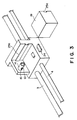
- an ink jet recording head 2 is mounted to an ink jet head carriage 1.
- the ink jet head carriage 1 is movable in engagement with a carriage moving shaft 3 and a carriage guide shaft 4 of the main assembly of the printer.
- the ink jet head carriage 1 comprises an ink supplying pipe 5 for supplying the ink to the ink jet head 2 and a subordinate container 6a, as shown in Figures 1 and 4.
- the subordinate container (sub-container) 6a communicates with an ink accumulating portion 6b by passages 7a and 7b, which all constitutes a first ink container 6.
- the first ink container 6 has a volume capacity of approximately 1 cc.
- the volume is selected because it is optimum from the standpoint of sufficiently reducing the ink jet head carriage 1 and that it can contain sufficient amount of ink even when the ink container is not mounted to the passage extending to the ink jet head 2.
- the volume of the first ink container 6 may be properly selected depending on the specifications of the main assembly of the printer, and therefore, the volume is not limiting.
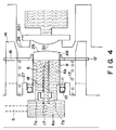
- the ink containing portion 6b comprises an ink cover 8 made of flexible material such as rubber and an ink cap A9 made of flexible or deformable elastic material such as rubber.
- An ink cover 8 is fixed by an ink jet head carriage 1, an O ring 10 and a fixing member 11.
- the ink cap A9 is fixed on a movable stay 12.
- the stay 12 is contacted to a top surface of a cut-away portion 15 of a cylinder 14 formed on an ink jet head carriage 1, by a spring 13.
- An ink connecting tube 17 is provided at a position enclosed by the ink containing portion 6b and the sub-containing 6a of the ink jet head carriage 1, that is, in the first ink container 6.
- the ink connecting tube 17 is in the form of a hollow cylinder, and the end thereof adjacent the ink cap A9 is cut obliquely as in an injection cannula for easy piercing the ink cap A9.
- the ink connecting tube 17 When the ink container is not connected to the ink jet head, the ink connecting tube 17 is entirely enclosed in the first ink container 6 and is covered with the ink. Therefore, the ink connecting tube 17 is prevented from contacting the air. For this reason, the ink jet recording head 2 is protected from air introduction thereto. Additionally, the viscosity increase of the ink in the ink connecting tube 17 and the solidification thereof are prevented. Furthermore, the leakage of the ink to the outside can be avoided.
- the ink jet head carriage 1 is provided in the main assembly of the printer.
- the operator mounts the ink container in the form of a replaceable cartridge on the ink jet head carriage 1.
- the ink container of the replaceable cartridge is called second ink container 19.
- the second ink container 19 comprises of plastic material or the like, which contains an ink bladder 20 containing the ink, an ink cap B21 made of flexible elastic material such as rubber to seal the ink bladder and the ink 22.
- the second ink container 19 comprises an engaging portion 24 engageable with a stopper 23 for fixing the second ink container 19 when it is mounted, a joint portion 28 engageable with a cylinder 14 formed as an engaging portion on an ink jet head carriage, and a guiding portion for guiding the entirety of the second ink container 19 relative to the ink jet head carriage 1, including an ink jet head carriage 1 side guide 25b and a second ink container 19 side guide 25a.
- the quantity of the ink contained in the second ink container 19 is approximately 20 cc.
- the volume capacity may be properly determined depending on the shape of the second ink container and shape and/or size of the ink jet head carriage 1, and therefore, the value of the ink volume capacity is not limiting.
- the operator pushes the second ink container 19 along the guiding portions 25a and 25b.
- joint portion 28 is inserted into the cylinder portion 14, and a top surface 26 of the joint portion 28 of the second ink container abuts the stay 12.
- the operator feels the spring force of the spring 13, and further pushes the second ink container, by which the central portions of the ink cap A9 and the ink cap B21 are pressed together.
- these caps are formed into outwardly convex, as indicated by reference numerals 29 and 30, respectively.
- the second ink container 19 is further pushed, and then, the stay 12 is pushed, so that the ink connecting tube 17 run through the ink cap A9. At this time, the ink cover 8 slacks to follow the stay 12.
- the ink connecting tube 19 run through the ink cap B21.
- the central portions of the ink caps A9 and B21 are press-contacted to each other, and therefore, no air is introduced into the ink connecting tube.
- the second ink container 19 abuts projections 27 of the ink jet head carriage 1, and substantially simultaneously, the stopper 23 and the locking portion 24 are engaged, so that the second ink container 19 is fixed.
- first ink container 6 and the second ink container 19 are connected properly to permit character or image recording using the large capacity second ink container 19, without the necessity for the air venting pumping action or the like at the time of connecting operation.
- the operator When the second ink container 19 is used up, the operator lowers the stopper 23 to release the second ink container 19 from the carriage. Then, the ink connecting tube 17 moves back relative to the ink cap B21 by the spring 13, and returns to the inside of the first ink container filled with the ink. Simultaneously, the second ink container 19 is pushed out by the spring 13 to a position for easy demounting on the ink jet head carriage 1. Then, the operator is permitted to easily takes the second ink container 19 out.
- the ink connecting tube 17 is at the fixed side, and the force applied to the second ink container 19 by the operator is used in which the ink cap A9 and the ink cap B21 are movable.
- the ink connecting tube 17 may be provided on the movable side.
- An ink jet recording head 102 is fixed on the ink jet head carriage 101, which moves in engagement with a carriage driving shaft 103 and a carriage guiding shaft 104 of a main assembly of the printer.
- the ink jet head carriage 101 comprises an ink supply pipe 105 for supplying the ink to the ink jet recording head 102 and a first ink container 106.
- the first ink container 106 in this embodiment has a volume capacity of approximately 1 cc. The volume capacity is determined from the standpoint that the size of the ink jet head carriage 1 is made sufficiently small, and it can contain a sufficient amount of the ink even when the ink container is mounted for the ink jet head 102. However, the volume capacity of the first ink container 106 may be changed depending on the specifications of the main assembly of the printer, and therefore, the value of the capacity is not limiting.
- the ink container 106 is sealed by an ink cap A 109 made of flexible or deformable elastic material such as rubber.
- the ink cover A109 is fixed on a stay 112.
- the stay 112 is fixed on the ink jet head carriage 101.
- An ink connecting tube 117 is provided in the first ink container 106 of the ink jet head carriage 101.
- the ink connecting tube 117 is in the form of a hollow cylinder, and an end thereof adjacent the ink cap A109 is cut inclined as in an injection cannula to permit easy piercing of the ink cap A109.
- the ink connecting tube 117 When the ink container is not connected, the entirety of the ink connecting tube 117 is contained in the first ink container 106 and is enclosed with the ink. Therefore, the ink connecting tube 117 is prevented from contact with the air, and therefore, there is no liability of the air introduction into the ink jet head 102. Similarly, the increase of the viscosity of the ink in the ink connecting tube 117 or the solidification thereof, can be avoided. Furthermore, the ink leakage to the outside can be avoided.
- the ink jet head carriage 101 is provided in the main assembly of the printer.
- the operator mounts an ink container in the form of a replaceable cartridge on the ink jet head carriage 101 to effect print the characters and images.
- the ink container of the replaceable cartridge is called as second ink container 119.
- the second ink container 119 comprises a housing made of plastic resin material or the like, which contains an ink bladder 120 containing the ink, an ink sealing cap B121 made of flexible elastic material such as rubber and the ink 122.
- the second ink container 119 includes an engaging portion 124 engageable with a stopper 123 for fixing the second ink container 119 when it is mounted, and a joint portion 128 for engagement with a cylinder 114 formed as a joint portion on the ink jet head carriage 101. Guiding portions for guiding the entirety of the second ink container 119 relative to the ink jet head carriage 101 are formed on the ink jet head carriage 101 and the second ink container 119, as indicated by references 125b and 125a, respectively.
- the ink capacity of the second ink container 119 is approximately 20 cc, but the capacity may be changed depending on the configuration of the second ink container 119, the configuration and the size of the ink jet head carriage 101. Therefore, this value is not limiting.
- the operator pushes the ink container 119 along the guides 125a and 125b. In the process of the pushing, the joint portion 128 enters the cylinder 114.
- the second ink container 119 is provided with a projection 130, and it abuts a driving lever 131 for moving the ink connecting tube 117.
- the driving lever 131 is urged by a spring 132, and is rotatably supported on the ink jet head carriage 1. An end of the driving lever 131 is engaged with the ink connecting tube 117 to permit movement of the ink connecting tube 117.
- the projection 130 of the second ink container 119 further pushes the driving lever 131, the ink connecting tube 117 is moved by the driving lever 131 to run through the ink cap A109, and substantially simultaneously therewith, the central portions of the ink cap A109 and an ink cap B121 are press-contacted to each other. So as to assure the press-contact at the central portions thereof between them, the central portions of the ink caps A109 and B121 are convexed toward each other.
- the ink connecting tube 117 run through the ink cap B121.
- the central portions of the ink cap A109 and the ink cap B121 are press-contacted to each other, and therefore, no air is introduced into the ink connecting tube 117.
- the second ink container abuts the stay 112 of the ink jet head carriage 1, and substantially simultaneously, the engagement is established between the stopper 121 and the locking portion 124, so that the second ink container 119 is fixed on the carriage.
- the second ink container 119 is properly connected with the first ink container 106, so that the recording of characters and images are possible with use of the ink in the large capacity second ink container, without the necessity for the air venting pumping action or the like at the time of the connecting operation.
- the operator When the second ink container 119 is used up, the operator lowers the stopper 123 to release the second ink container 119 from the carriage. When it is released, the ink connecting tube 117 moves back relative to the ink cap B121 by the spring force 132, and returns to the inside of the first container 106 filled with the ink. Simultaneously, the second ink container 119 is pushed out by the spring 132 and moves to a easy demounting position on the ink jet head carriage 101. Thus, the operator can easily take the second ink container 119 out of the carriage.
- the apparatus of the first or second embodiment is provided with an element for detecting presence and/or absence of the ink container mounted on the recording head or mounted on the carriage.
- the detecting element is effective to additionally detect the property of the ink container.
- detecting elements 1380 constituting a pair are mounted on side surfaces of a head holder 1350 to detect presence or absence of the ink container 6.
- One of the element is a positive electrode, and the other is a negative electrode. They are electrically connected to respective contact on a board by unshown leads.
- An end of detecting element 1380 extends along a side surface of the head holder 1350.
- detection pins 1360 constituting a pair are mounted on the ink container 6 to detect the amount of the ink in the ink containing chamber 20 of the ink container 6.
- An end of each of the detecting pins 1360 is provided along a side surface of the ink container, and the other end projects into the ink containing chamber 20.
- both of the pins When the ends of both of the pins are in the ink, they are electrically connected through the ink.
- the detecting pins 1360 When the ink container 6 is mounted on the head holder 1350, the detecting pins 1360 are contacted to the respective detecting elements 1380. If the inside ends of the two detecting pins 1360 are in the ink, that is, if the amount of the ink is sufficient, the detecting pins 1360 are electrically connected through the ink.
- the state of a detecting circuit which will be described hereinafter is changed. On the basis of the change of the circuit, a discriminating circuit of the main assembly of the recording apparatus detects the presence of the ink in the ink container, and a signal indicative of it is supplied to a control circuit.
- the permitting signal can be transmitted to the main assembly when it is mounted on the main assembly.
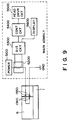
- Figure 9 is a block diagram of a ink amount detecting circuit for detecting the ink container and for detecting the amount of the remaining ink, using the detecting contacts 1380 and detecting pins 1360.
- a current detecting circuit 5200 detects the current depending on connection or disconnection between the detecting contact 1380 and the detecting pin 1360 and depending on the ink amount, and the result of the detection is transmitted to the discriminating circuit 5300 which discriminates the presence or absence of the ink container and discriminates whether the sufficient amount of ink remains or not.
- the signal indicative of the results of the discrimination is supplied to a control circuit 5400.
- the carriage and the recording head are driven by the recording head driving circuit 550 and the like (the driving circuit for the carriage is not shown) so as to perform the normal recording operation. If the discriminating circuit 5300 discriminates the absence of the ink, the recording operation is disabled by the control circuit 5400.
- the control circuit 5400 actuates a display device 5600 to display the results of the discriminating circuit 5300.
- the two detecting pins 1380 are used to detect the absence or presence of the ink. It is an alternative that a value indicative of the nature of the ink may be detected by the two detecting pins 1380 to detect the remaining amount of the ink.
- the current detecting circuit 5200 and the discriminating circuit 5300 are provided in the main assembly of the recording apparatus, but this may be provided in the recording head cartridge.
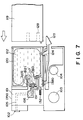
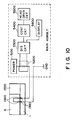
- Figures 7 and 10 show another embodiment, in which detecting contact 1360 for detecting presence or absence of the ink container are provided in the carriage 1.
- detecting contact 1360 for detecting presence or absence of the ink container are provided in the carriage 1.
- the presence or absence of the ink container and/or the ink is detected when the head cartridge is mounted on the carriage.
- the amount of the ink can be detected on the basis of the electric connection.
- the present invention is particularly suitably usable in an ink jet recording head and recording apparatus wherein thermal energy by an electrothermal transducer, laser beam or the like is used to cause a change of state of the ink to eject or discharge the ink. This is because the high density of the picture elements and the high resolution of the recording are possible.
- the typical structure and the operational principle are preferably the ones disclosed in U.S. Patent Nos. 4,723,129 and 4,740,796.
- the principle and structure are applicable to a so-called on-demand type recording system and a continuous type recording system.
- it is suitable for the on-demand type because the principle is such that at least one driving signal is applied to an electrothermal transducer disposed on a liquid (ink) retaining sheet or liquid passage, the driving signal being enough to provide such a quick temperature rise beyond a departure from nucleation boiling point, by which the thermal energy is provided by the electrothermal transducer to produce film boiling on the heating portion of the recording head, whereby a bubble can be formed in the liquid (ink) corresponding to each of the driving signals.
- the liquid (ink) is ejected through an ejection outlet to produce at least one droplet.
- the driving signal is preferably in the form of a pulse, because the development and contraction of the bubble can be effected instantaneously, and therefore, the liquid (ink) is ejected with quick response.
- the driving signal in the form of the pulse is preferably such as disclosed in U.S. Patents Nos. 4,463,359 and 4,345,262.
- the temperature increasing rate of the heating surface is preferably such as disclosed in U.S. Patent No. 4,313,124.
- the structure of the recording head may be as shown in U.S. Patent Nos. 4,558,333 and 4,459,600 wherein the heating portion is disposed at a bent portion, as well as the structure of the combination of the ejection outlet, liquid passage and the electrothermal transducer as disclosed in the above-mentioned patents.
- the present invention is applicable to the structure disclosed in Japanese Laid-Open Patent Application No. 123670/1984 wherein a common slit is used as the ejection outlet for plural electrothermal transducers, and to the structure disclosed in Japanese Laid-Open Patent Application No. 138461/1984 wherein an opening for absorbing pressure wave of the thermal energy is formed corresponding to the ejecting portion. This is because the present invention is effective to perform the recording operation with certainty and at high efficiency irrespective of the type of the recording head.
- the present invention is effectively applicable to a so-called full-line type recording head having a length corresponding to the maximum recording width.
- a recording head may comprise a single recording head and plural recording head combined to cover the maximum width.
- the present invention is applicable to a serial type recording head wherein the recording head is fixed on the main assembly, to a replaceable chip type recording head which is connected electrically with the main apparatus and can be supplied with the ink when it is mounted in the main assembly, or to a cartridge type recording head having an integral ink container.
- the provisions of the recovery means and/or the auxiliary means for the preliminary operation are preferable, because they can further stabilize the effects of the present invention.
- preliminary heating means which may be the electrothermal transducer, an additional heating element or a combination thereof.
- means for effecting preliminary ejection (not for the recording operation) can stabilize the recording operation.
- the recording head mountable may be a single corresponding to a single color ink, or may be plural corresponding to the plurality of ink materials having different recording color or density.
- the present invention is effectively applicable to an apparatus having at least one of a monochromatic mode mainly with black, a multi-color mode with different color ink materials and/or a full-color mode using the mixture of the colors, which may be an integrally formed recording unit or a combination of plural recording heads.
- the ink has been liquid. It may be, however, an ink material which is solidified below the room temperature but liquefied at the room temperature. Since the ink is controlled within the temperature not lower than 30 °C and not higher than 70°C to stabilize the viscosity of the ink to provide the stabilized ejection in usual recording apparatus of this type, the ink may be such that it is liquid within the temperature range when the recording signal is the present invention is applicable to other types of ink. In one of them, the temperature rise due to the thermal energy is positively prevented by consuming it for the state change of the ink from the solid state to the liquid state. Another ink material is solidified when it is left, to prevent the evaporation of the ink.
- the ink is liquefied, and the liquefied ink may be ejected.
- Another ink material may start to be solidified at the time when it reaches the recording material.
- the present invention is also applicable to such an ink material as is liquefied by the application of the thermal energy.
- Such an ink material may be retained as a liquid or solid material in through holes or recesses formed in a porous sheet as disclosed in Japanese Laid-Open Patent Application No. 56847/1979 and Japanese Laid-Open Patent Application No. 71260/1985. The sheet is faced to the electrothermal transducers. The most effective one for the ink materials described above is the film boiling system.
- the ink jet recording apparatus may be used as an output terminal of an information processing apparatus such as computer or the like, as a copying apparatus combined with an image reader or the like, or as a facsimile machine having information sending and receiving functions.
- the ink container can be mounted without introduction of the external air into the ink passage from the ink container to the ink jet recording head. Therefore, the pumping mechanism is not required for discharging the air introduced at the time of connection of the ink container to the apparatus or to the recording head. Therefore, the running cost is reduced by saving the wasteful ink discharged by the air discharging pumping operation.
- the structure of the main assembly of the printer may be simplified and can be reduced in the size. In addition, the cost thereof may be lowered. Since the connecting tube is not exposed, and therefore, the safety is further assured. Simultaneously, the ink is prevented from externally leaking through the connecting tube. Furthermore, the increase in the viscosity of the ink and the resultant clogging of the connecting tube, can be avoided.
- the recording operation of the ink jet recording apparatus is disables when the ink container is not mounted, and therefore, the shortage of the ink during the recording operation can be avoided.
Claims (7)
- Tintenstrahlkartusche, die folgende Bauteile aufweist:einen Aufzeichnungskopfabschnitt, der einen Aufzeichnungskopf (2) mit Tintenaustoßauslässen zum Bewirken einer Aufzeichnung und einen hermetisch gedichteten ersten Tintenbehälter (6a) mit einer Fluidverbindung mit dem Aufzeichnungskopf umfaßt;einen zweiten Tintenbehälter (19) zum Aufbewahren von Tinte, um diese dem ersten Tintenbehälter zuzuführen;ein Tintenanschlußelement (17) zum Einrichten einer Fluidverbindung zwischen dem ersten und zweiten Tintenbehälter, um Tinte dem ersten Tintenbehälter von dem zweiten Tintenbehälter zuzuführen, dadurch gekennzeichnet, daß der erste Tintenbehälter zumindest teilweise durch ein erstes elastisches Element (A9) gebildet wird; der zweite Tintenbehälter zumindest teilweise durch ein zweites elastisches Element (B21) gebildet wird; das Tintenanschlußelement vollständig in den ersten Tintenbehälter aufgenommen wird bevor der erste und der zweite Tintenbehälter mit einer Fluidverbindung zueinander angeordnet werden; und das Tintenanschlußelement sich durch das erste und zweite elastische Element erstreckt, wenn der erste und zweite Behälter mit einer Fluidverbindung angeordnet sind.
- Kartusche nach Anspruch 1, die des weiteren eine Druckeinrichtung (13) aufweist, um das erste elastische Element in eine Richtung zu drücken, wobei die Fluidverbindung mit dem zweiten Tintenbehälter verhindert wird.
- Kartusche nach Anspruch 1 oder 2, wobei das Tintenanschlußelement in dem ersten Tintenbehälter fixiert ist.
- Kartusche nach Anspruch 1 oder 2, wobei das Tintenanschlußelement in dem ersten Tintenbehälter beweglich ist, und wobei der Aufzeichnungskopfabschnitt Einrichtungen (131, 132) zum Bewegen des Tintenanschlußelements umfaßt.
- Kartusche nach einem der vorangestellten Ansprüche, die des weiteren einen Elektrodenstift (1360) in dem zweiten Tintenbehälter aufweist, um eine Restmenge der darin befindlichen Tinte zu erfassen.
- Tintenstrahlaufzeichnungsgerät, das eine Kartusche nach einem der vorangestellten Ansprüche und einen Schlitten zum Tragen des Aufzeichnungskopfabschnitts und des zweiten Tintenbehälters aufweist.
- Gerät nach Anspruch 6 mit einer Kartusche nach Anspruch 5, welches des weiteren folgende Bauteile aufweist: eine Erfassungseinrichtung (Fig. 9, 10), um sowohl zu erfassen, ob der Tintenbehälter montiert ist oder nicht, als auch wie viel Tinte übrig ist; und einen Elektrodenschaltkreis zum Aufnehmen eines Signals von dem Elektrodenstift.
Priority Applications (1)
| Application Number | Priority Date | Filing Date | Title |
|---|---|---|---|
| EP19920300652 EP0496642B1 (de) | 1991-01-25 | 1992-01-24 | Tintenstrahlaufzeichnungsgerät und abnehmbare Tintenstrahlkassette |
Applications Claiming Priority (13)
| Application Number | Priority Date | Filing Date | Title |
|---|---|---|---|
| JP776991 | 1991-01-25 | ||
| JP7769/91 | 1991-01-25 | ||
| JP7760/91 | 1991-01-25 | ||
| JP7761/91 | 1991-01-25 | ||
| JP775991 | 1991-01-25 | ||
| JP776191 | 1991-01-25 | ||
| JP777091A JPH04247961A (ja) | 1991-01-25 | 1991-01-25 | インクジェット記録装置に用いられるインクタンク及びインクジェット記録装置 |
| JP7759/91 | 1991-01-25 | ||
| JP7770/91 | 1991-01-25 | ||
| JP776091 | 1991-01-25 | ||
| EP92300588 | 1992-01-23 | ||
| EP92300588A EP0496620B1 (de) | 1991-01-25 | 1992-01-23 | Tintenstrahlaufzeichnungsgerät und Tintenkassette für dieses Gerät |
| EP19920300652 EP0496642B1 (de) | 1991-01-25 | 1992-01-24 | Tintenstrahlaufzeichnungsgerät und abnehmbare Tintenstrahlkassette |
Publications (3)
| Publication Number | Publication Date |
|---|---|
| EP0496642A2 EP0496642A2 (de) | 1992-07-29 |
| EP0496642A3 EP0496642A3 (en) | 1993-03-10 |
| EP0496642B1 true EP0496642B1 (de) | 1997-08-06 |
Family
ID=27562078
Family Applications (1)
| Application Number | Title | Priority Date | Filing Date |
|---|---|---|---|
| EP19920300652 Expired - Lifetime EP0496642B1 (de) | 1991-01-25 | 1992-01-24 | Tintenstrahlaufzeichnungsgerät und abnehmbare Tintenstrahlkassette |
Country Status (1)
| Country | Link |
|---|---|
| EP (1) | EP0496642B1 (de) |
Families Citing this family (26)
| Publication number | Priority date | Publication date | Assignee | Title |
|---|---|---|---|---|
| JP3021149B2 (ja) * | 1991-12-19 | 2000-03-15 | キヤノン株式会社 | インクジェット記録手段 |
| US5648807A (en) * | 1992-09-10 | 1997-07-15 | Seiko Epson Corporation | Ink jet recording apparatus having an antismear sheet deformation discharge system |
| DE4345337B4 (de) * | 1992-09-10 | 2004-03-04 | Seiko Epson Corp. | Drucker und Befestigungsvorrichtung für Tintenpatrone |
| CA2112182C (en) * | 1992-12-25 | 2000-06-27 | Masami Ikeda | Detachable ink jet unit and ink jet apparatus |
| IT1258135B (it) * | 1992-12-28 | 1996-02-20 | Olivetti Canon Ind Spa | Dispositivo per conservare e mantenere rifornite d'inchiostro le cartucce di una stampante a getto d'inchiostro. |
| DE69310696T2 (de) * | 1992-12-28 | 1997-09-25 | Canon Kk | Tintenstrahlkopfkartusche und Tintenbehälter dafür |
| IT1261876B (it) * | 1993-09-23 | 1996-06-03 | Olivetti Canon Ind Spa | Modulo di stampa a getto di inchiostro ricaricabile |
| US5574489A (en) * | 1994-03-30 | 1996-11-12 | Hewlett-Packard Company | Ink cartridge system for ink-jet printer |
| JP3267449B2 (ja) * | 1994-05-31 | 2002-03-18 | セイコーエプソン株式会社 | インクジェット式記録装置 |
| CA2156809C (en) | 1994-08-24 | 2003-11-11 | Hiroyuki Inoue | Ink container for ink jet printer, holder for the container carriage for the holder and ink jet printer |
| AU773523B2 (en) * | 1994-08-24 | 2004-05-27 | Canon Kabushiki Kaisha | Ink container for ink jet printer, holder for the container carriage for the holder and ink jet printer |
| US6771378B2 (en) * | 1994-10-20 | 2004-08-03 | Canon Kabushiki Kaisha | Information processing apparatus which obtains information concerning residual ink amount from an attached ink jet printer |
| US6022103A (en) * | 1995-02-07 | 2000-02-08 | Canon Kabushiki Kaisha | Method for positioning an ink cartridge, and the ink cartridge and ink jet recording apparatus used for such method |
| JPH10235890A (ja) | 1996-06-25 | 1998-09-08 | Seiko Epson Corp | インクカートリッジ |
| JP3710230B2 (ja) | 1996-10-04 | 2005-10-26 | キヤノン株式会社 | インク検出方法、およびインクジェット記録装置 |
| DE29619296U1 (de) * | 1996-11-07 | 1997-01-16 | Laser Care Modul Recycl Gmbh | Kartusche zum Nachfüllen von Tinte in eine Druckpatrone |
| JP2001063090A (ja) | 1999-04-27 | 2001-03-13 | Canon Inc | インクタンク、該インクタンクに用いられる弁ユニット、前記インクタンクの製造方法、前記インクタンクを備えたインクジェットヘッドカートリッジおよびインクジェット記録装置 |
| JP3770315B2 (ja) | 2000-12-25 | 2006-04-26 | セイコーエプソン株式会社 | インクカートリッジ |
| US7438401B2 (en) | 2002-06-17 | 2008-10-21 | Seiko Epson Corporation | Inkjet recording apparatus and ink cartridge |
| JP4631253B2 (ja) | 2002-06-17 | 2011-02-16 | セイコーエプソン株式会社 | インクジェット記録装置、及びインクカートリッジ |
| AR049674A1 (es) | 2003-08-08 | 2006-08-30 | Seiko Epson Corp | Recipiente contenedor de liquido a suministrar a un aparato de consumo de dicho liquido |
| JP2005343053A (ja) * | 2004-06-04 | 2005-12-15 | Sony Corp | インクカートリッジ |
| JP4946751B2 (ja) | 2006-11-06 | 2012-06-06 | セイコーエプソン株式会社 | 容器ホルダ、液体消費装置及び液体収容容器 |
| TWI581981B (zh) | 2006-11-06 | 2017-05-11 | Seiko Epson Corp | A liquid container, a container holder, and a liquid consuming device |
| JP5972131B2 (ja) * | 2012-09-25 | 2016-08-17 | キヤノン株式会社 | 画像形成装置、カートリッジ、画像形成装置本体、及びカートリッジの誤挿入防止システム |
| CN104797987B (zh) * | 2012-09-25 | 2019-05-31 | 佳能株式会社 | 成像装置、盒和成像装置系统 |
Family Cites Families (5)
| Publication number | Priority date | Publication date | Assignee | Title |
|---|---|---|---|---|
| JPH0698774B2 (ja) * | 1984-02-09 | 1994-12-07 | キヤノン株式会社 | インク容器 |
| JP3066867B2 (ja) * | 1988-10-31 | 2000-07-17 | キヤノン株式会社 | インクジェットプリンタ、記録ヘッド、インクカセット及びインクジェット記録用販売セット |
| JP2575205B2 (ja) * | 1989-01-13 | 1997-01-22 | キヤノン株式会社 | インクタンク |
| DE69033377T2 (de) * | 1989-08-05 | 2000-06-29 | Canon Kk | Tintenstrahlaufzeichnungsgerät und Tintenkassette dafür |
| DE3938173A1 (de) * | 1989-11-16 | 1990-06-07 | Siemens Ag | Tintenschreibeinrichtung |
-
1992
- 1992-01-24 EP EP19920300652 patent/EP0496642B1/de not_active Expired - Lifetime
Also Published As
| Publication number | Publication date |
|---|---|
| EP0496642A2 (de) | 1992-07-29 |
| EP0496642A3 (en) | 1993-03-10 |
Similar Documents
| Publication | Publication Date | Title |
|---|---|---|
| US5500664A (en) | Ink jet recording apparatus and detachably mountable ink jet cartridge | |
| EP0496642B1 (de) | Tintenstrahlaufzeichnungsgerät und abnehmbare Tintenstrahlkassette | |
| US5448274A (en) | Ink jet recording apparatus and carriage mechanism therefor | |
| EP0424133B1 (de) | Kassette mit Tintenvorratsbehälter auf einem Farbstrahlgerät aufstellbar | |
| US6290344B1 (en) | Vented ink container with internal ink absorber, and ink cartridge having such an ink container | |
| EP0640483B1 (de) | Verfahren und Vorrichtung zur Bestimmung des Tintenpegels in einer Patrone | |
| US5138344A (en) | Ink jet apparatus and ink jet cartridge therefor | |
| EP0547874B1 (de) | Tintenstrahlaufzeichungsmittel und zugehörige Verpackung | |
| US5565899A (en) | Ink jet apparatus having an ink passage divided into regions by a filter | |
| EP0418817B1 (de) | Tintenstrahlaufzeichnungskopf und Tintenstrahlaufzeichnungsgerät welches ihn verwendet | |
| EP0604940B1 (de) | Tintenstrahlkopfkartusche und Tintenbehälter dafür | |
| EP0562717A1 (de) | Ventilmechanismus für Flüssigkeitsbehälter in einer Flüssigkeitsaufzeichnungsvorrichtung | |
| GB2273684A (en) | Replenishing ink-jet cartridges with ink. | |
| USRE36279E (en) | Ink jet apparatus and ink jet cartridge therefor | |
| CA2051964C (en) | Ink cartridge and ink jet apparatus usable with ink cartridge | |
| EP1281527B1 (de) | Flüssigkeitsausstossaufzeichnungsgerät | |
| KR950010439B1 (ko) | 잉크제트 기록헤드와 이것을 사용하는 잉크제트 기록장치 | |
| JP3267493B2 (ja) | インクジェット記録装置及びこれに用いられるインクタンク | |
| KR960008963Y1 (ko) | 잉크제트장치 및 이를 위한 잉크제트카트리지 |
Legal Events
| Date | Code | Title | Description |
|---|---|---|---|
| PUAI | Public reference made under article 153(3) epc to a published international application that has entered the european phase |
Free format text: ORIGINAL CODE: 0009012 |
|
| AK | Designated contracting states |
Kind code of ref document: A2 Designated state(s): AT BE CH DE DK ES FR GB GR IT LI LU NL PT SE |
|
| PUAL | Search report despatched |
Free format text: ORIGINAL CODE: 0009013 |
|
| AK | Designated contracting states |
Kind code of ref document: A3 Designated state(s): AT BE CH DE DK ES FR GB GR IT LI LU NL PT SE |
|
| 17P | Request for examination filed |
Effective date: 19930723 |
|
| 17Q | First examination report despatched |
Effective date: 19950315 |
|
| GRAG | Despatch of communication of intention to grant |
Free format text: ORIGINAL CODE: EPIDOS AGRA |
|
| GRAH | Despatch of communication of intention to grant a patent |
Free format text: ORIGINAL CODE: EPIDOS IGRA |
|
| GRAH | Despatch of communication of intention to grant a patent |
Free format text: ORIGINAL CODE: EPIDOS IGRA |
|
| GRAA | (expected) grant |
Free format text: ORIGINAL CODE: 0009210 |
|
| AK | Designated contracting states |
Kind code of ref document: B1 Designated state(s): AT BE CH DE DK ES FR GB GR IT LI LU NL PT SE |
|
| PG25 | Lapsed in a contracting state [announced via postgrant information from national office to epo] |
Ref country code: CH Effective date: 19970806 Ref country code: NL Free format text: LAPSE BECAUSE OF FAILURE TO SUBMIT A TRANSLATION OF THE DESCRIPTION OR TO PAY THE FEE WITHIN THE PRESCRIBED TIME-LIMIT Effective date: 19970806 Ref country code: AT Effective date: 19970806 Ref country code: DK Free format text: LAPSE BECAUSE OF NON-PAYMENT OF DUE FEES Effective date: 19970806 Ref country code: BE Effective date: 19970806 Ref country code: GR Free format text: LAPSE BECAUSE OF FAILURE TO SUBMIT A TRANSLATION OF THE DESCRIPTION OR TO PAY THE FEE WITHIN THE PRESCRIBED TIME-LIMIT Effective date: 19970806 Ref country code: ES Free format text: THE PATENT HAS BEEN ANNULLED BY A DECISION OF A NATIONAL AUTHORITY Effective date: 19970806 Ref country code: LI Effective date: 19970806 |
|
| REF | Corresponds to: |
Ref document number: 156423 Country of ref document: AT Date of ref document: 19970815 Kind code of ref document: T |
|
| REG | Reference to a national code |
Ref country code: CH Ref legal event code: EP |
|
| REF | Corresponds to: |
Ref document number: 69221339 Country of ref document: DE Date of ref document: 19970911 |
|
| ITF | It: translation for a ep patent filed |
Owner name: SOCIETA' ITALIANA BREVETTI S.P.A. |
|
| PG25 | Lapsed in a contracting state [announced via postgrant information from national office to epo] |
Ref country code: SE Effective date: 19971106 |
|
| ET | Fr: translation filed | ||
| PG25 | Lapsed in a contracting state [announced via postgrant information from national office to epo] |
Ref country code: PT Effective date: 19971110 |
|
| NLV1 | Nl: lapsed or annulled due to failure to fulfill the requirements of art. 29p and 29m of the patents act | ||
| PG25 | Lapsed in a contracting state [announced via postgrant information from national office to epo] |
Ref country code: LU Free format text: LAPSE BECAUSE OF NON-PAYMENT OF DUE FEES Effective date: 19980124 |
|
| REG | Reference to a national code |
Ref country code: CH Ref legal event code: PL |
|
| PLBE | No opposition filed within time limit |
Free format text: ORIGINAL CODE: 0009261 |
|
| STAA | Information on the status of an ep patent application or granted ep patent |
Free format text: STATUS: NO OPPOSITION FILED WITHIN TIME LIMIT |
|
| 26N | No opposition filed | ||
| REG | Reference to a national code |
Ref country code: GB Ref legal event code: IF02 |
|
| PGFP | Annual fee paid to national office [announced via postgrant information from national office to epo] |
Ref country code: GB Payment date: 20060110 Year of fee payment: 15 |
|
| PGFP | Annual fee paid to national office [announced via postgrant information from national office to epo] |
Ref country code: FR Payment date: 20060125 Year of fee payment: 15 |
|
| PGFP | Annual fee paid to national office [announced via postgrant information from national office to epo] |
Ref country code: IT Payment date: 20060131 Year of fee payment: 15 |
|
| PGFP | Annual fee paid to national office [announced via postgrant information from national office to epo] |
Ref country code: DE Payment date: 20060322 Year of fee payment: 15 |
|
| PG25 | Lapsed in a contracting state [announced via postgrant information from national office to epo] |
Ref country code: DE Free format text: LAPSE BECAUSE OF NON-PAYMENT OF DUE FEES Effective date: 20070801 |
|
| GBPC | Gb: european patent ceased through non-payment of renewal fee |
Effective date: 20070124 |
|
| REG | Reference to a national code |
Ref country code: FR Ref legal event code: ST Effective date: 20070930 |
|
| PG25 | Lapsed in a contracting state [announced via postgrant information from national office to epo] |
Ref country code: GB Free format text: LAPSE BECAUSE OF NON-PAYMENT OF DUE FEES Effective date: 20070124 |
|
| PG25 | Lapsed in a contracting state [announced via postgrant information from national office to epo] |
Ref country code: FR Free format text: LAPSE BECAUSE OF NON-PAYMENT OF DUE FEES Effective date: 20070131 |
|
| PG25 | Lapsed in a contracting state [announced via postgrant information from national office to epo] |
Ref country code: IT Free format text: LAPSE BECAUSE OF NON-PAYMENT OF DUE FEES Effective date: 20070124 |