EP0692586A1 - Fassade - Google Patents
Fassade Download PDFInfo
- Publication number
- EP0692586A1 EP0692586A1 EP95110871A EP95110871A EP0692586A1 EP 0692586 A1 EP0692586 A1 EP 0692586A1 EP 95110871 A EP95110871 A EP 95110871A EP 95110871 A EP95110871 A EP 95110871A EP 0692586 A1 EP0692586 A1 EP 0692586A1
- Authority
- EP
- European Patent Office
- Prior art keywords
- channel
- spar
- facade according
- strip
- shaped
- Prior art date
- Legal status (The legal status is an assumption and is not a legal conclusion. Google has not performed a legal analysis and makes no representation as to the accuracy of the status listed.)
- Granted
Links
Images
Classifications
-
- E—FIXED CONSTRUCTIONS
- E04—BUILDING
- E04B—GENERAL BUILDING CONSTRUCTIONS; WALLS, e.g. PARTITIONS; ROOFS; FLOORS; CEILINGS; INSULATION OR OTHER PROTECTION OF BUILDINGS
- E04B2/00—Walls, e.g. partitions, for buildings; Wall construction with regard to insulation; Connections specially adapted to walls
- E04B2/88—Curtain walls
- E04B2/96—Curtain walls comprising panels attached to the structure through mullions or transoms
- E04B2/965—Connections of mullions and transoms
-
- E—FIXED CONSTRUCTIONS
- E04—BUILDING
- E04D—ROOF COVERINGS; SKY-LIGHTS; GUTTERS; ROOF-WORKING TOOLS
- E04D3/00—Roof covering by making use of flat or curved slabs or stiff sheets
- E04D3/02—Roof covering by making use of flat or curved slabs or stiff sheets of plane slabs, slates, or sheets, or in which the cross-section is unimportant
- E04D3/06—Roof covering by making use of flat or curved slabs or stiff sheets of plane slabs, slates, or sheets, or in which the cross-section is unimportant of glass or other translucent material; Fixing means therefor
- E04D3/08—Roof covering by making use of flat or curved slabs or stiff sheets of plane slabs, slates, or sheets, or in which the cross-section is unimportant of glass or other translucent material; Fixing means therefor with metal glazing bars
- E04D2003/0818—Roof covering by making use of flat or curved slabs or stiff sheets of plane slabs, slates, or sheets, or in which the cross-section is unimportant of glass or other translucent material; Fixing means therefor with metal glazing bars the supporting section of the glazing bar consisting of several parts, e.g. compound sections
- E04D2003/0825—Roof covering by making use of flat or curved slabs or stiff sheets of plane slabs, slates, or sheets, or in which the cross-section is unimportant of glass or other translucent material; Fixing means therefor with metal glazing bars the supporting section of the glazing bar consisting of several parts, e.g. compound sections the metal section covered by parts of other material
- E04D2003/0831—Glazing gaskets of particular shape
-
- E—FIXED CONSTRUCTIONS
- E04—BUILDING
- E04D—ROOF COVERINGS; SKY-LIGHTS; GUTTERS; ROOF-WORKING TOOLS
- E04D3/00—Roof covering by making use of flat or curved slabs or stiff sheets
- E04D3/02—Roof covering by making use of flat or curved slabs or stiff sheets of plane slabs, slates, or sheets, or in which the cross-section is unimportant
- E04D3/06—Roof covering by making use of flat or curved slabs or stiff sheets of plane slabs, slates, or sheets, or in which the cross-section is unimportant of glass or other translucent material; Fixing means therefor
- E04D3/08—Roof covering by making use of flat or curved slabs or stiff sheets of plane slabs, slates, or sheets, or in which the cross-section is unimportant of glass or other translucent material; Fixing means therefor with metal glazing bars
- E04D2003/0818—Roof covering by making use of flat or curved slabs or stiff sheets of plane slabs, slates, or sheets, or in which the cross-section is unimportant of glass or other translucent material; Fixing means therefor with metal glazing bars the supporting section of the glazing bar consisting of several parts, e.g. compound sections
- E04D2003/0837—Sections comprising intermediate parts of insulating material
Definitions
- the invention relates to a facade consisting of horizontally and vertically arranged spars, a spar, for example holding a glass pane, can be fastened with fastening means to the spar, and a seal is provided between the spar and the spar.
- Facades of the type described at the outset are used, for example, in the construction of conservatories or cladding for buildings. Between the vertical bars, the posts, horizontally arranged bars are provided, which are welded to the vertical posts, for example.
- the mullions transoms or the spars in general, rectangular ones are preferred Profiles use. However, other profiles can also be used.
- Windows for example, have to be attached to this construction made of vertical and horizontal bars. The attachment takes place with the interim storage of a seal. Cover strips or pressed profiles are used to hold the windows, which are fastened to the outside of the vertical or horizontal bars with fastening means, usually screws.
- fastening means usually screws.
- For assembly it is known to drill screw holes in the spars at predetermined locations. If a screw hole cannot be used during assembly, there is often the need to dismantle the partially assembled window in order to install a replacement hole. This leads to increased effort when installing the facade.
- metal plates or metal covers can be installed in the facade.
- the invention has set itself the task of making an arrangement on the facade, with which it is possible to significantly simplify and accelerate the assembly process.
- an essentially U-shaped screw channel is provided on the spar, the opening facing the U's towards the cover strip and receiving the fastening means.
- a strip which has the screw channel to be inserted into a receiving channel provided on the spar along the axis of the receiving channel, the two channels being essentially U-shaped and the opening of the U. is directed towards the cover strip.
- the spars of the facades consist of a steel profile, for example. Aluminum is used as the material for the cover strips.
- the screw channel is inserted as a bar into a receiving channel provided on the spar along the axis of the receiving channel. It is advantageous if the screw channel is made of aluminum and the receiving channel is made of steel. The receiving channel is only connected to the spar at a few points, for example glued or welded.
- the receiving channel has an inwardly bent projection at the ends of the legs of the U. Furthermore, it is favorable if the screw channel strip has an outwardly projecting retaining lug at the ends of the legs of the U, which cooperates with the projection. Such interaction of the screw channel with the receiving channel prevents the screw channel from being pulled out of the opening of the receiving channel when the screws are screwed in.
- the screw channel has a longitudinal ribbing which interacts with fastening means for the cover strip.
- This longitudinal ribbing acts as a counter thread for the screwed-in screws.
- the U-shaped receiving channel is fastened to the spar with its web. This enables the U-shaped channel to be easily attached to the spar.
- the U-shaped receiving channel is molded, for example rolled, into the spar.
- the screw channel strip can simply be joined to the spar without additional fastening means. It is recommended if the receiving channel has a widening at its inner end, into which the screw channel strip engages like a hammer head.
- the seal is U-shaped, surrounds the receiving channel and the leg base of the U-shaped seal rests on the spar.
- Such a configuration of the seal seals the spar and the receiving channel from the cover strip or the glass pane pressed against the spar by the cover strip.
- Such a seal can also be used if, for example, a metal cladding is installed instead of a washer.
- a strip is provided on the inside of the web of the U-shaped seal.
- the strip is pressed into the U-shaped screw channel, whereby the seal is held on the screw or receiving channel.
- the bar has a longitudinal rib, which interacts with the longitudinal rib of the screw channel.
- the water discharge channels are arranged to drain the water from horizontally or vertically arranged seals.
- Appropriate recesses and recesses in the seal make it possible to connect the water discharge channels from horizontally and vertically arranged seals, as a result of which the water that is collected in these channels is drained off.
- an obliquely arranged surface is provided on the outside of the web of the U-shaped seal.
- This obliquely arranged surface which extends in the longitudinal direction of the seal and is, for example, symmetrical to the central axis of the symmetrically designed seal, serves, for example, as a sealing lip and lies against the cover strip.
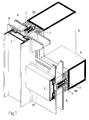
- the facade consists essentially of vertically and horizontally arranged bars 5 and 6.
- the vertically arranged bars 5 are designed, for example, as posts.
- the horizontal bars 6 serve as bars connecting the posts.
- the spars 5 and 6 form a frame, in the interstices of which glass panes etc. are inserted.
- the spars, as shown in Fig. 1, consist for example of square profile material. However, other spar profiles can also be provided for other configurations of the facade according to the invention.
- the window panes in particular insulating glass panes, are designated by 8.
- the outside of the spars 5 and 6 form a contact surface 50 and 60 for the window pane 8.
- Seals 1 and 2 are provided between the glass pane 8 and the spars 5 and 6.
- a profile 3 is welded onto the spar 5 and 6 for fastening the cover strip 7. To achieve good thermal insulation, it is provided that the profile 3 is attached to the spar 5 and 6 at only a few points.
- the profile 3 is designed as a receiving channel 3 and has a U-shape 30.
- the fastening means which are not shown here, but which connect the cover strip 7 to the spar 5 and 6, engage directly in the receiving channel 3 and fasten the cover strip 7 to the receiving channel 3.
- the receiving channel 3 receives a screw channel strip 40.
- the screw channel 4 is also U-shaped, the openings of the U's 31 (the receiving channel 3) and 41 (the screw channel 4) being directed outward in the direction of the cover strip 7.
- the seals 1 and 2 overlap the receiving or screwing channels 3 and 4 applied to the bars 5 and 6.
- the seal 1 and 2 is located between the spar or the channels fastened to the spar and the glass pane 8 or the cover strip 7.
- cover strip 7 In order to connect the cover strip 7 to the screw channel 4, fastening means, for example screws, are provided. To cover this, a cover 70 is pushed onto the cover strip 7.
- the receiving channel 3 has projections 33 projecting inwards. For example, this is shown in FIG. 4.
- the screw channel 4 is inserted into the receiving channel 3, namely along the longitudinal axis of the channel.
- a force is now exerted which pulls the screw channel 4 against the projections 33 of the receiving channel 3 and firmly connects it.
- the Heat conduction in the metal profiles hindered. It has been found that it is sufficient to connect the receiving channel to the spar at only a few points, for example by welding. Furthermore, it has been found that the contact area between the channel and the spar can be reduced without running the risk that the stability suffers. This reduction in the contact areas is achieved by angling 32 in the web area 34 of the U-shaped receiving channel 3.
- the screw channel strip 40 also has a U-shaped configuration.
- the inside 43 of the screw channel which is accessible through the opening 41, has a longitudinal rib 44.
- the longitudinal ribbing 44 makes it easier to screw in screws, for example, as fastening means for fastening the cover strip 7, and a secure connection is established.
- outwardly projecting retaining lugs 42 are provided, which cooperate with the inwardly projecting projections 33 of the receiving channel 3. This prevents the screw channel 4 from sliding out of the receiving channel 3 along the opening 31.
- the seals 1 and 2 are generally U-shaped, the leg feet 10 and 20 each having outwardly projecting areas.
- the seal has a foot region 11 and 21 and a head region 12 and 22.
- the foot region 11 and 21 is essentially formed by the leg feet 10 and 20.
- the web of the U-shaped seals 1 and 2 form the head region 12 and 22.
- the foot area 11, 21, in particular the leg feet 10, 20 rests on the bars 5 and 6, in particular on the support surfaces 50 and 60.
- the seals 1 and 2 completely overlap the assembled receiving or screwing channel 3, 4.
- the leg feet 10 and 20 have a greater thickness than the legs 15 and 25.
- the reinforced leg foot 10 and 20 in the foot region 11 and 21 of the seals 1 and 2 seals the glass pane 8 against the bars 5 and 6.
- surfaces 14 and 24 are provided on the web of the seal. These surfaces 14 and 24 interact, for example, with sealing elements of the cover strip 7.
- the surfaces 14 and 24 are arranged symmetrically to the central axis of the seal.
- a channel 29 is provided in the seal 2, for example, for draining off water, for example condensed water.
- This seal 2 is provided, for example, as a bolt seal with horizontally extending bars 6.
- the receiving channel 35 has been molded into the spar 61, for example in that a groove was formed by a corresponding rolling process, which serves as a receiving channel.
- This groove is preferably provided with an extension 36 at the inner end, so that the correspondingly adapted screw channel strip 45 engages with the foot 46 like a hammer head into the extension.
- the seal which in the embodiment according to FIG. 6 used corresponds largely or completely to the seal according to FIG. 2 or FIG. 3.
Abstract
Description
- Die Erfindung betrifft eine Fassade, bestehend aus horizontal und vertikal angeordneten Holmen, wobei an dem Holm eine, zum Beispiel eine Glasscheibe haltende Abdeckleiste mit Befestigungsmitteln befestigbar ist und wobei zwischen dem Holm und der Abdeckleiste eine Dichtung vorgesehen ist.
- Fassaden der eingangs beschriebenen Art werden beispielsweise beim Bau von Wintergärten oder Verkleidungen für Gebäude verwendet. Zwischen den senkrechten Holmen, den Pfosten, sind horizontal angeordnete Riegel vorgesehen, die zum Beispiel mit den senkrechten Pfosten verschweißt sind. Für die Pfosten, Riegel oder allgemein die Holme finden bevorzugt rechteckige Profile Verwendung. Es können aber auch andere Profile angewandt werden.
- An dieser Konstruktion aus senkrechten und waagrechten Holmen sind zum Beispiel Fenster zu befestigen. Die Befestigung erfolgt unter Zwischenlagerung einer Dichtung. Zur Halterung der Fenster dienen Abdeckleisten oder Preßprofile, die auf der Außenseite der senkrechten bzw. waagrechten Holme mit Befestigungsmitteln, üblicherweise Schrauben, befestigt werden. Für die Montage ist es bekannt, in die Holme Schraubbohrungen an vorbestimmten Stellen einzubringen. Wenn nun bei der Montage eine Schraubbohrung nicht verwendbar ist, ergibt sich häufig die Notwendigkeit, das teilweise montierte Fenster wieder zu demontieren, um eine Ersatzbohrung anzubringen. Dies führt zu einem erhöhten Aufwand bei der Montage der Fassade.
- In der Fassade können zum Beispiel auch Metallplatten oder Metallabdeckungen montiert werden.
- Die Erfindung hat es sich zur Aufgabe gemacht, eine Anordnung an der Fassade zu treffen, mit der es möglich ist, den Montagevorgang wesentlich zu vereinfachen und zu beschleunigen.
- Erfindungsgemäß wird vorgeschlagen, daß an dem Holm ein im wesentlichen U-förmiger Schraubkanal vorgesehen ist, wobei die Öffnung die U's zur Abdeckleiste hin gerichtet ist und die Befestigungsmittel aufnimmt. Bei einem Montagefehler ist es nun nicht mehr notwendig, eine neue Schraubbohrung anzubringen, denn der Schraubkanal bietet eine Vielzahl von Einschraubmöglichkeiten für das Befestigungsmittel entlang des Holmes. Es ist somit nicht mehr notwendig, bei einem Montagefehler die ganze Fensterscheibe wieder zu demontieren, um eine neue Schraubbohrung zu setzen. Daraus resultiert bei der Montage der Fassade eine erhebliche Zeiteinsparung.
- Es ist gefunden worden, daß es günstig ist, wenn eine Leiste, die den Schraubkanal aufweist, in einem, an dem Holm vorgesehenen Aufnahmekanal längs der Achse des Aufnahmekanals eingeschoben ist, die beiden Kanäle im wesentlichen U-förmig ausgestaltet sind und die Öffnung des U's zur Abdeckleiste hin gerichtet ist. Die Holme der Fassaden bestehen zum Beispiel aus einem Stahlprofil. Als Material für die Abdeckleisten wird Aluminium verwendet.
- Um Kontaktkorrision zu vermeiden, insbesondere auf den als Sichtflächen wirkenden Abdeckleisten, ist man bestrebt, in dem Sichtbereich nur Aluminium zu verwenden. Jedoch ist das Befestigen eines Aluminium-Schraubkanals auf den Stahlholmen unverhältnismäßig aufwendig und teuer. Aus diesem Grund wird der Schraubkanal als Leiste in einen an dem Holm vorgesehenen Aufnahmekanal längs der Achse des Aufnahmekanals eingeschoben. Hierbei ist es günstig, wenn der Schraubkanal aus Aluminium und der Aufnahmekanal aus Stahl ist. Der Aufnahmekanal ist nur an wenigen Stellen mit dem Holm verbunden, zum Beispiel verklebt oder verschweißt.
- Es ist von Vorteil, wenn der Aufnahmekanal an den Enden der Schenkel des U's einen nach innen gebogenen Vorsprung aufweist. Des weiteren ist es günstig, wenn die Schraubkanalleiste an den Enden der Schenkel des U's eine nach außen vorstehende Haltenase aufweist, die mit dem Vorsprung zusammenwirkt. Durch ein solches Zusammenwirken des Schraubkanals mit dem Aufnahmekanal wird vermieden, daß der Schraubkanal bei dem Einschrauben der Schrauben aus der Öffnung des Aufnahmekanals herausgezogen wird.
- Es ist ferner von Vorteil, wenn der Schraubkanal eine Längsrippung aufweist, die mit Befestigungsmitteln für die Abdeckleiste zusammenwirkt. Diese Längsrippung wirkt als Gegengewinde für die eingedrehten Schrauben.
- Ferner ist vorgesehen, daß der U-förmige Aufnahmekanal mit seinem Steg am Holm befestigt ist. Dadurch wird eine einfache Befestigung des U-förmigen Kanals auf dem Holm realisiert.
- Bei einer anderen Ausführungsform der Erfindung ist der U-förmige Aufnahmekanal in den Holm eingeformt, beispielsweise eingewalzt. Bei dieser Bauweise kann einfach die Schraubkanalleiste ohne zusätzliche Befestigungsmittel mit dem Holm zusammengefügt werden. Dabei empfiehlt es sich, wenn der Aufnahmekanal an seinem inneren Ende eine Verbreiterung aufweist, in die die Schraubkanalleiste hammerkopfartig eingreift.
- Es ist günstig, wenn die Dichtung U-förmig gestaltet ist, den Aufnahmekanal umschließt und der Schenkelfuß der U-förmigen Dichtung am Holm anliegt. Durch eine solche Ausgestaltung der Dichtung wird der Holm und der Aufnahmekanal gegenüber der Abdeckleiste bzw. der durch die Abdeckleiste an den Holm gedrückten Glasscheibe abgedichtet. Eine solche Dichtung ist auch zu verwenden, wenn zum Beispiel an Stelle einer Scheibe eine Metallverkleidung montiert wird.
- Bei einer bevorzugten Ausführungsform der Erfindung ist vorgesehen, daß eine Leiste auf der Innenseite des Steges der U-förmigen Dichtung vorgesehen ist. Die Leiste wird in den U-förmigen Schraubkanal eingedrückt, wodurch die Dichtung auf dem Schraub- bzw. Aufnahmekanal gehalten ist.
- Ferner wird vorgesehen, daß die Leiste eine Längsrippung aufweist, die mit der Längsrippung des Schraubkanals zusammenwirkt.
- Es ist von Vorteil, wenn in dem Schenkelfuß der Dichtung ein Wasserabführkanal, insbesondere für Kondenswasser, vorgesehen ist.
- Es ist günstig, wenn die Wasserabführkanäle von horizontal oder vertikal angeordneten Dichtungen das Wasser ableitend angeordnet sind. Durch entsprechende Aussparungen und Ausnehmungen an der Dichtung ist es möglich, die Wasserabführkanäle von horizontal und vertikal angeordneten Dichtungen zu verbinden, wodurch das Wasser, das in diesen Kanälen gesammelt wird, abgeleitet wird.
- Es ist von Vorteil, wenn auf der Außenseite des Stegel der U-förmigen Dichtung eine schräg angeordnete Fläche vorgesehen ist. Diese schräg angeordnete Fläche, die sich in Längsrichtung der Dichtung erstreckt und zum Beispiel symmetrisch zur Mittelachse der symmetrisch gestalteten Dichtung ausgebildet ist, dient beispielsweise als Dichtlippe und liegt an der Abdeckleiste an.
- In der Zeichnung ist die Erfindung schematisch dargestellt. Es zeigen:
- Fig. 1
- in perspektivischer Ansicht eine Ausführungsform der erfindungsgemäßen Fassade,
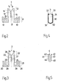
- Fig. 2
- ein Dichtungsprofil der erfindungsgemäßen Fassade,
- Fig. 3
- eine weitere Variante eines Dichtungsprofiles einer erfindungsgemäßen Fassade,
- Fig. 4
- den Aufnahmekanal einer erfindungsgemäßen Fassade,
- Fig. 5
- eine Schraubkanalleiste, die mit einem Aufnahmekanal gemäß Fig. 4 zusammenwirken kann und
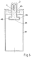
- Fig. 6
- einen Querschnitt durch einen Holm mit einem Schraubkanal und einem Aufnahmekanal in einer abgewandelten Ausführungsform.
- In Fig. 1 ist in einer perspektivischen Darstellung der Aufbau der Fassade gezeigt. Die Fassade besteht im wesentlichen aus senkrecht und waagrecht angeordneten Holmen 5 und 6, Die senkrecht angeordneten Holme 5 sind zum Beispiel als Pfosten ausgestaltet. Die waagrechten Holme 6 dienen als die Pfosten verbindende Riegel. Die Holme 5 und 6 bilden ein Gerüst, in dessen Zwischenräumen zum Beispiel Glasscheiben usw. eingesetzt sind. Die Holme, wie sie in Fig. 1 gezeigt sind, bestehen beispielsweise aus Vierkantprofilmaterial. Für andere Ausgestaltungen der erfindungsgemäßen Fassade können aber auch andere Holmenprofile vorgesehen werden.
- Die Fensterscheiben, insbesondere Isolierglasscheiben, sind mit 8 bezeichnet. Die Außenseiten der Holme 5 und 6 bilden hierbei eine Anlagefläche 50 und 60 für die Fensterscheibe 8. Zwischen der Glasscheibe 8 und den Holmen 5 und 6 sind Dichtungen 1 und 2 vorgesehen.
- Als Preßleiste zum Festhalten der Fensterscheibe 8 dient die Abdeckleiste 7, die von außen gegen den Holm 5 oder 6 geschraubt wird. Für die Befestigungen der Abdeckleiste 7 ist auf dem Holm 5 und 6 ein Profil 3 aufgeschweißt. Zur Erzielung einer guten Wärmedämmung ist vorgesehen, daß das Profil 3 nur an wenigen Punkten auf dem Holm 5 und 6 befestigt ist.
- Das Profil 3 ist als Aufnahmekanal 3 ausgestaltet und weist eine U-Form 30 auf. In einer Ausgestaltung der Erfindung ist zum Beispiel vorgesehen, daß die Befestigungsmittel, die hier nicht gezeigt sind, aber die Abdeckleiste 7 mit dem Holm 5 und 6 verbinden, direkt in den Aufnahmekanal 3 eingreifen und die Abdeckleiste 7 an dem Aufnahmekanal 3 befestigen.
- In der dargestellten, verbesserten Ausführungsform der Erfindung wird vorgeschlagen, daß der Aufnahmekanal 3 eine Schraubkanalleiste 40 aufnimmt. Auch der Schraubkanal 4 ist U-förmig ausgebildet, wobei jeweils die Öffnungen der U's 31 (des Aufnahmekanals 3) und 41 (des Schraubkanals 4) nach außen in Richtung der Abdeckleiste 7 gerichtet sind. Für eine optimale Abdichtung ist vorgesehen, daß die Dichtungen 1 und 2 die auf den Holmen 5 und 6 aufgebrachten Aufnahme- bzw. Schraubkanäle 3 und 4 übergreifen. Die Dichtung 1 und 2 befindet sich zwischen dem Holm bzw. den an dem Holm befestigten Kanälen und der Glasscheibe 8 bzw. der Abdeckleiste 7.
- Um die Abdeckleiste 7 mit dem Schraubkanal 4 zu verbinden, sind Befestigungsmittel, zum Beispiel Schrauben, vorgesehen. Um diese zu verdecken, ist auf der Abdeckleiste 7 eine Blende 70 aufgeschoben.
- Um ein Herausgleiten des Schraubkanales 4 aus dem Aufnahmekanal 3 zu vermeiden, weist der Aufnahmekanal 3 nach innen vorstehende Vorsprünge 33 auf. Dies ist zum Beispiel in Fig. 4 gezeigt. Für die Montage des Aufnahmekanals und des Schraubkanals ist vorgesehen, daß der Schraubkanal 4 in den Aufnahmekanal 3 eingeschoben wird, und zwar längs der Längsachse des Kanals. Durch ein Verschrauben der Abdeckleiste 7 in dem Schraubkanal 4 wird nun eine Kraft bewirkt, die den Schraubkanal 4 gegen die Vorsprünge 33 des Aufnahmekanals 3 zieht und fest verbindet.
- Um eine möglichst hohe Wärmedämmung zu erreichen, wird die Wärmeleitung in den Metallprofilen (zwischen dem Holm und dem Aufnahmekanal 3) behindert. Es ist gefunden worden, daß es ausreicht, den Aufnahmekanal nur an wenigen Stellen mit dem Holm zu verbinden, zum Beispiel anzuschweißen. Des weiteren ist gefunden worden, daß die Kontaktfläche zwischen Kanal und Holm verringert werden kann, ohne Gefahr zu laufen, daß die Stabilität darunter leidet. Diese Reduzierung der Kontaktflächen ist durch eine Abwinkelung 32 im Stegbereich 34 des U-förmig 30 gestalteten Aufnahmekanals 3 erreicht.
- Die Schraubkanalleiste 40, wie in Fig. 5 gezeigt, weist ebenfalls eine U-förmige Ausgestaltung auf. Die Innenseite 43 des Schraubkanales, die durch die Öffnung 41 zugänglich ist, weist eine Längsrippung 44 auf. Durch die Längsrippung 44 wird das Einschrauben beispielsweise von Schrauben als Befestigungsmittel zum Befestigen der Abdeckleiste 7 erleichtert und eine sichere Verbindung hergestellt. An den Schenkelenden des U-förmigen Schraubkanals 4 sind nach außen vorstehende Haltenasen 42 vorgesehen, die mit den nach innen vorstehenden Vorsprüngen 33 des Aufnahmekanals 3 zusammenwirken. Dadurch wird ein Herausgleiten des Schraubkanals 4 aus dem Aufnahmekanal 3 längs der Öffnung 31 verhindert.
- Die Dichtungen 1 und 2 sind im allgemeinen U-förmig ausgebildet, wobei die Schenkelfüße 10 und 20 jeweils nach außen vorstehende Bereiche aufweisen. Die Dichtung weist einen Fußbereich 11 und 21 und einen Kopfbereich 12 und 22 auf. Der Fußbereich 11 und 21 wird im wesentlichen durch die Schenkelfüße 10 und 20 gebildet. Der Steg der U-förmigen Dichtungen 1 und 2 bilden den Kopfbereich 12 und 22.
- Im eingebauten Zustand liegt der Fußbereich 11,21, insbesondere die Schenkelfüße 10,20 auf den Holmen 5 und 6, insbesondere auf den Auflageflächen 50 und 60 auf.
- Die Dichtungen 1 und 2 übergreifen hierbei den montierten Aufnahme- bzw. Schraubkanal 3,4 vollständig. Die Schenkelfüße 10 und 20 weisen eine größere Dicke auf als die Schenkel 15 und 25. Der verstärkte Schenkelfuß 10 und 20 im Fußbereich 11 und 21 der Dichtungen 1 und 2 dichtet die Glasscheibe 8 gegen die Holmen 5 und 6 ab.
- Im oberen Bereich 12 und 22 sind auf dem Steg der Dichtung schräg angeordnete Flächen 14 und 24 vorgesehen. Diese Flächen 14 und 24 wirken zum Beispiel mit Dichtelementen der Abdeckleiste 7 zusammen. Die Flächen 14 und 24 sind symmetrisch zur Mittelachse der Dichtung angeordnet.
- Auf der Innenseite des Steges 16 und 26 ist eine zusätzliche, nach innen in die U-förmige Öffnung des Schraubkanals 4 eingreifende Leiste 13,23 vorgesehen. Diese Leiste 13,23 weist ebenfalls eine Längsrippung 17,27 auf, die mit der Längsrippung 44 des Schraubkanals 4 zusammenwirkt. Dadurch sind die Dichtungen 1,2 in dem Schraubkanal 4 gehalten.
- Zum Ableiten von Wasser, zum Beispiel Kondenswasser, ist in der Dichtung 2 beispielsweise ein Kanal 29 vorgesehen. Diese Dichtung 2 ist zum Beispiel als Riegeldichtung bei waagrecht verlaufenden Holmen 6 vorgesehen.
- In der Fig. 6 ist ein abgewandeltes Ausführungsbeispiel dargestellt. Bei dieser Ausführungsform ist in den Holm 61 der Aufnahmekanal 35 eingeformt worden, beispielsweise dadurch, daß durch einen entsprechenden Walzvorgang eine Nut gebildet wurde, die als Aufnahmekanal dient. Diese Nut ist vorzugsweise am inneren Ende mit einer Erweiterung 36 versehen, so daß die entsprechend angepaßte Schraubkanalleiste 45 mit ihrem Fuß 46 hammerkopfartig in die Erweiterung eingreift.
- Die Abdichtung, die bei der Ausführungsform nach der Fig. 6 verwendet wird, entspricht weitgehend bzw. vollständig der Dichtung gemäß Fig. 2 oder Fig. 3.
- Die jetzt mit der Anmeldung und später eingereichten Ansprüche sind Versuche zur Formulierung ohne Präjudiz für die Erzielung weitergehenden Schutzes.
- Die in den abhängigen Ansprüchen angeführten Rückbeziehungen weisen auf die weitere Ausbildung des Gegenstandes des Hauptanspruches durch die Merkmale des jeweiligen Unteranspruches hin. Jedoch sind diese nicht als ein Verzicht auf die Erzielung eines selbständigen, gegenständlichen Schutzes für die Merkmale der rückbezogenen Unteransprüche zu verstehen.
- Merkmale, die bislang nur in der Beschreibung offenbart wurden, können im Laufe des Verfahrens als von erfindungswesentlicher Bedeutung, zum Beispiel zur Abgrenzung vom Stand der Technik beansprucht werden.
Claims (16)
- Fassade, bestehend aus horizontal und vertikal angeordneten Holmen, wobei an dem Holm eine, zum Beispiel eine Glasscheibe haltende Abdeckleiste mit Befestigungsmitteln befestigbar ist und wobei zwischen dem Holm und der Abdeckleiste eine Dichtung vorgesehen ist, dadurch gekennzeichnet, daß an dem Holm (5,6) ein im wesentlichen U-förmiger Schraubkanal vorgesehen ist, wobei die Öffnung des U's zur Abdeckleiste (7) hin gerichtet ist und die Befestigungsmittel aufnimmt.
- Fassade nach Anspruch 1, dadurch gekennzeichnet, daß eine Leiste (40), die den Schraubkanal (4) aufweist, in einen an dem Holm (5,6) vorgesehenen Aufnahmekanal (3) längs der Achse des Aufnahmekanals (3) eingeschoben ist, die beiden Kanäle (3,4) im wesentlichen U-förmig (30,40) ausgestaltet sind und die Öffnung (31,41) des U's zur Abdeckleiste (7) hin gerichtet ist.
- Fassade nach einem oder beiden der vorhergehenden Ansprüche, dadurch gekennzeichnet, daß der Aufnahmekanal (3) an dem Ende des Schenkels des U's einen nach innen gebogenen Vorsprung (33) aufweist.
- Fassade nach einem oder mehreren der vorhergehenden Ansprüche, dadurch gekennzeichnet, daß die Schraubkanalleiste (40) an dem Ende des Schenkels des U's eine nach außen vorstehende Haltenase (42) aufweist, die mit dem Vorsprung (33) zusammenwirkt.
- Fassade nach einem oder mehreren der vorhergehenden Ansprüche, dadurch gekennzeichnet, daß der Schraubkanal (4) eine Längsrippung (44) aufweist, die mit Befestigungsmitteln für die Abdeckleiste (7) zusammenwirkt.
- Fassade nach einem oder mehreren der vorhergehenden Ansprüche, dadurch gekennzeichnet, daß die Schraubkanalleiste (40) aus Aluminium gefertigt ist.
- Fassade nach einem oder mehreren der vorhergehenden Ansprüche, dadurch gekennzeichnet, daß der Aufnahmekanal (3) als Stahlprofil ausgebildet ist.
- Fassade nach einem oder mehreren der vorhergehenden Ansprüche, dadurch gekennzeichnet, daß der U-förmige Aufnahmekanal (3) mit seinem Steg (34) am Holm (5,6) befestigt ist.
- Fassade nach einem oder mehreren der vorhergehenden Ansprüche, dadurch gekennzeichnet, daß der U-förmige Aufnahmekanal (35) in den Holm (61) eingeformt, insbesondere eingewalzt ist.
- Fassade nach einem oder mehreren der vorhergehenden Ansprüche, dadurch gekennzeichnet, daß der eingeformte Aufnahmekanal (35) am inneren Ende eine Erweiterung (36) aufweist, in die die Schraubkanalleiste (45) mit einem Fuß (46) hammerkopfartig eingreift.
- Fassade nach einem oder mehreren der vorhergehenden Ansprüche, dadurch gekennzeichnet, daß die Dichtung (1,2) U-förmig gestaltet ist, den Aufnahme- bzw. Schraubkanal umschließt und der Schenkelfuß (10,20) der U-förmigen Dichtung (1,2) am Holm (5,6) anliegt.
- Fassade nach einem oder mehreren der vorhergehenden Ansprüche, dadurch gekennzeichnet, daß eine Leiste (13,23) auf der Innenseite des Steges der U-förmigen Dichtung (1,2) vorgesehen ist.
- Fassade nach einem oder mehreren der vorhergehenden Ansprüche, dadurch gekennzeichnet, daß die Leiste (13,23) eine Längsrippung (17,27) aufweist, die mit der Längsrippung (44) des Schraubkanals (4) zusammenwirkt.
- Fassade nach einem oder mehreren der vorhergehenden Ansprüche, dadurch gekennzeichnet, daß in dem Schenkelfuß (20) der Dichtung (2) ein Wasserabführkanal (29), insbesondere für Kondenswasser, vorgesehen ist.
- Fassade nach einem oder mehreren der vorhergehenden Ansprüche, dadurch gekennzeichnet, daß die Wasserabführkanäle von horizontal und vertikal angeordneten Dichtungen das Wasser ableitend angeordnet sind.
- Fassade nach einem oder mehreren der vorhergehenden Ansprüche, dadurch gekennzeichnet, daß auf der Außenseite des Steges (16,26) der U-förmigen Dichtung (1,2) eine schräg angeordnete Fläche (14,24) vorgesehen ist.
Applications Claiming Priority (2)
| Application Number | Priority Date | Filing Date | Title |
|---|---|---|---|
| DE9411552U | 1994-07-16 | ||
| DE9411552U DE9411552U1 (de) | 1994-07-16 | 1994-07-16 | Fassade |
Publications (3)
| Publication Number | Publication Date |
|---|---|
| EP0692586A1 true EP0692586A1 (de) | 1996-01-17 |
| EP0692586B1 EP0692586B1 (de) | 1999-02-24 |
| EP0692586B2 EP0692586B2 (de) | 2008-12-24 |
Family
ID=6911250
Family Applications (1)
| Application Number | Title | Priority Date | Filing Date |
|---|---|---|---|
| EP95110871A Expired - Lifetime EP0692586B2 (de) | 1994-07-16 | 1995-07-12 | Fassade |
Country Status (6)
| Country | Link |
|---|---|
| EP (1) | EP0692586B2 (de) |
| AT (1) | ATE176943T1 (de) |
| DE (2) | DE9411552U1 (de) |
| DK (1) | DK0692586T4 (de) |
| ES (1) | ES2130475T3 (de) |
| GR (1) | GR3029859T3 (de) |
Cited By (6)
| Publication number | Priority date | Publication date | Assignee | Title |
|---|---|---|---|---|
| EP0955420A2 (de) | 1998-05-05 | 1999-11-10 | EVG Bauprofil-System Entwicklungs- und Vermarktungsgesellschaft mbH | Fassadenprofil |
| WO2002053854A2 (de) * | 2000-12-29 | 2002-07-11 | SCHÜCO International KG | Fassade und/oder dach und aufsatzdichtung |
| EP1267009A2 (de) * | 2001-06-13 | 2002-12-18 | EVG Bauprofil-System Entwicklungs- und Vermarktungsgesellschaft mbH | Fassadenkonstruktion |
| DE19804925B4 (de) * | 1998-02-07 | 2004-12-02 | Bernhard Steinert | Haltevorrichtung für Füllelemente in einer Wandkonstruktion |
| EP1698736A2 (de) | 2005-02-25 | 2006-09-06 | Raico Bautechnik GmbH | Fassade und Verfahren zur Herstellung einer Fassade |
| WO2017083991A1 (de) | 2015-11-18 | 2017-05-26 | Jansen Ag | Profilschiene für eine gebäudefassade |
Families Citing this family (6)
| Publication number | Priority date | Publication date | Assignee | Title |
|---|---|---|---|---|
| DE29613579U1 (de) * | 1996-08-06 | 1996-09-19 | Eberspaecher J | Dichtungsanordnung für einen Holm, insbesondere aus Aluminium, als Trägerteil einer Fassaden- oder Dachkonstruktion |
| DE19741469A1 (de) * | 1997-09-19 | 1999-03-25 | Sommer Metallbau Stahlbau Gmbh | Vorrichtung zum Befestigen von Verglasungen, Fassaden oder dergleichen an einem Anschlußprofil |
| DE19741468B4 (de) * | 1997-09-19 | 2005-02-03 | Sommer Metallbau-Stahlbau Gmbh & Co. Kg | Vorrichtung zur Befestigung von Verglasungen, Fassaden oder dergleichen |
| DE19855031C5 (de) * | 1998-11-28 | 2016-01-07 | Raico Bautechnik Gmbh | Verfahren und Vorrichtung zum Befestigen eines Fassadenprofiles |
| DE10319001B4 (de) * | 2003-04-25 | 2008-11-06 | Hermann Gutmann Werke Ag | Fassade oder Dach mit mehreren Entwässerungsebenen |
| DE102006033456B3 (de) * | 2006-07-19 | 2007-10-18 | Rp Technik Gmbh Profilsysteme | Profilschiene aus kaltgeformtem Stahl |
Citations (11)
| Publication number | Priority date | Publication date | Assignee | Title |
|---|---|---|---|---|
| US2976970A (en) * | 1957-03-29 | 1961-03-28 | Pittsburgh Plate Glass Co | Frame support for a panel |
| FR2162954A5 (de) * | 1971-11-24 | 1973-07-20 | Wieland Werke Ag | |
| FR2455137A1 (fr) * | 1979-04-26 | 1980-11-21 | Hueck Fa E | Ossature, notamment pour elements rideaux formant des chassis de fenetres ou de portes, des facades, des murs de piscines couvertes et equivalents |
| GB2078837A (en) * | 1980-06-28 | 1982-01-13 | Pillar Pg Ltd | Glazing bars |
| DE8416009U1 (de) * | 1984-05-25 | 1987-06-04 | Schuermann & Co Heinz | Fassade oder dach in einer metall-glas ausfuehrung |
| WO1987006291A1 (en) * | 1986-04-15 | 1987-10-22 | Construction Utilities Group Limited | Curtain walling |
| EP0436868A2 (de) * | 1990-01-12 | 1991-07-17 | Reynolds Aluminium Deutschland, Internationale Vertriebsgesellschaft Mbh | Traggerippe für eine oder an einer Fassadenwand |
| WO1993016249A1 (en) * | 1992-02-10 | 1993-08-19 | Mogens Vilfred Rasmussen | Panel supporting building structure |
| DE4210575A1 (de) * | 1992-03-31 | 1993-10-07 | Herbert Lacker | Unterkonstruktion für Glasdächer und Glasfassaden |
| EP0619403A1 (de) * | 1993-04-07 | 1994-10-12 | W. HARTMANN & CO (GMBH & CO) | Aussenwandkonstruktion für Gebäude oder Schrägdächer |
| EP0641902A1 (de) * | 1993-08-26 | 1995-03-08 | METRA METALLURGICA TRAFILATI ALLUMINIO S.p.A. | Profilsatz zur Herstellung von durchgehenden Fassaden für Zivilgebäude oder dergleichen |
Family Cites Families (9)
| Publication number | Priority date | Publication date | Assignee | Title |
|---|---|---|---|---|
| US392974A (en) * | 1888-11-13 | Coal-washer | ||
| US4428171A (en) * | 1982-03-12 | 1984-01-31 | Atlantic Richfield Company | Thermal storefront system |
| DE3624491C3 (de) * | 1986-07-19 | 1997-04-24 | Hueck Eduard Gmbh Co Kg | Scheibenhalterung zum Aufhängen von Scheibenfeldern an einer Trägerkonstruktion bei Ganzglas-Fassaden |
| DE3639848A1 (de) * | 1986-11-21 | 1988-05-26 | Herbert Lacker | Dichtungsstreifen fuer glasdaecher und glasfasaden |
| DE8632187U1 (de) * | 1986-12-02 | 1988-03-31 | Metallbau Filser & Freisinger Gmbh & Co Produktions-Kg, 8045 Ismaning, De | |
| DE3715055C2 (de) * | 1987-05-06 | 1997-05-22 | Brandschutz Indverband | Feuerbeständige verglaste Fassadenkonstruktion |
| DE3906035A1 (de) * | 1989-02-27 | 1990-08-30 | Herbert Lacker | Rahmenkonstruktion |
| AT392814B (de) * | 1989-05-22 | 1991-06-25 | Meusburger Walter | Tragkonstruktion fuer ein aus scheibenartigen platten gebildetes dach bzw. wand |
| DE4206593A1 (de) * | 1992-03-03 | 1993-09-16 | Herbert Lacker | Dichtungsanordnung fuer glasdaecher und glasfassaden |
-
1994
- 1994-07-16 DE DE9411552U patent/DE9411552U1/de not_active Expired - Lifetime
-
1995
- 1995-07-12 DE DE59505136T patent/DE59505136D1/de not_active Expired - Lifetime
- 1995-07-12 ES ES95110871T patent/ES2130475T3/es not_active Expired - Lifetime
- 1995-07-12 AT AT95110871T patent/ATE176943T1/de active
- 1995-07-12 DK DK95110871T patent/DK0692586T4/da active
- 1995-07-12 EP EP95110871A patent/EP0692586B2/de not_active Expired - Lifetime
-
1999
- 1999-04-05 GR GR990400948T patent/GR3029859T3/el unknown
Patent Citations (11)
| Publication number | Priority date | Publication date | Assignee | Title |
|---|---|---|---|---|
| US2976970A (en) * | 1957-03-29 | 1961-03-28 | Pittsburgh Plate Glass Co | Frame support for a panel |
| FR2162954A5 (de) * | 1971-11-24 | 1973-07-20 | Wieland Werke Ag | |
| FR2455137A1 (fr) * | 1979-04-26 | 1980-11-21 | Hueck Fa E | Ossature, notamment pour elements rideaux formant des chassis de fenetres ou de portes, des facades, des murs de piscines couvertes et equivalents |
| GB2078837A (en) * | 1980-06-28 | 1982-01-13 | Pillar Pg Ltd | Glazing bars |
| DE8416009U1 (de) * | 1984-05-25 | 1987-06-04 | Schuermann & Co Heinz | Fassade oder dach in einer metall-glas ausfuehrung |
| WO1987006291A1 (en) * | 1986-04-15 | 1987-10-22 | Construction Utilities Group Limited | Curtain walling |
| EP0436868A2 (de) * | 1990-01-12 | 1991-07-17 | Reynolds Aluminium Deutschland, Internationale Vertriebsgesellschaft Mbh | Traggerippe für eine oder an einer Fassadenwand |
| WO1993016249A1 (en) * | 1992-02-10 | 1993-08-19 | Mogens Vilfred Rasmussen | Panel supporting building structure |
| DE4210575A1 (de) * | 1992-03-31 | 1993-10-07 | Herbert Lacker | Unterkonstruktion für Glasdächer und Glasfassaden |
| EP0619403A1 (de) * | 1993-04-07 | 1994-10-12 | W. HARTMANN & CO (GMBH & CO) | Aussenwandkonstruktion für Gebäude oder Schrägdächer |
| EP0641902A1 (de) * | 1993-08-26 | 1995-03-08 | METRA METALLURGICA TRAFILATI ALLUMINIO S.p.A. | Profilsatz zur Herstellung von durchgehenden Fassaden für Zivilgebäude oder dergleichen |
Cited By (9)
| Publication number | Priority date | Publication date | Assignee | Title |
|---|---|---|---|---|
| DE19804925B4 (de) * | 1998-02-07 | 2004-12-02 | Bernhard Steinert | Haltevorrichtung für Füllelemente in einer Wandkonstruktion |
| EP0955420A2 (de) | 1998-05-05 | 1999-11-10 | EVG Bauprofil-System Entwicklungs- und Vermarktungsgesellschaft mbH | Fassadenprofil |
| WO2002053854A2 (de) * | 2000-12-29 | 2002-07-11 | SCHÜCO International KG | Fassade und/oder dach und aufsatzdichtung |
| WO2002053854A3 (de) * | 2000-12-29 | 2002-09-26 | Schueco Int Kg | Fassade und/oder dach und aufsatzdichtung |
| HRP20030519B1 (en) * | 2000-12-29 | 2011-03-31 | Sch�Co International Kg | Facade and or roof and seal |
| EP1267009A2 (de) * | 2001-06-13 | 2002-12-18 | EVG Bauprofil-System Entwicklungs- und Vermarktungsgesellschaft mbH | Fassadenkonstruktion |
| EP1267009A3 (de) * | 2001-06-13 | 2003-11-26 | EVG Bauprofil-System Entwicklungs- und Vermarktungsgesellschaft mbH | Fassadenkonstruktion |
| EP1698736A2 (de) | 2005-02-25 | 2006-09-06 | Raico Bautechnik GmbH | Fassade und Verfahren zur Herstellung einer Fassade |
| WO2017083991A1 (de) | 2015-11-18 | 2017-05-26 | Jansen Ag | Profilschiene für eine gebäudefassade |
Also Published As
| Publication number | Publication date |
|---|---|
| DK0692586T4 (da) | 2009-04-14 |
| DK0692586T3 (da) | 1999-09-27 |
| GR3029859T3 (en) | 1999-07-30 |
| DE9411552U1 (de) | 1994-11-10 |
| ES2130475T3 (es) | 1999-07-01 |
| DE59505136D1 (de) | 1999-04-01 |
| EP0692586B1 (de) | 1999-02-24 |
| EP0692586B2 (de) | 2008-12-24 |
| ATE176943T1 (de) | 1999-03-15 |
Similar Documents
| Publication | Publication Date | Title |
|---|---|---|
| EP0841456B1 (de) | Lamellenfenster für im wesentlichen senkrechte Fassaden | |
| EP0692586A1 (de) | Fassade | |
| EP1020579B1 (de) | Fassade oder Lichtdach mit einer Dichtung | |
| DE19601505C1 (de) | Glasrandhalterung | |
| DE4007247A1 (de) | Trocken-druck-verglasungsanordnung fuer fassaden- und dach-konstruktionen in pfosten-riegel-bauweise | |
| DE3912136A1 (de) | Festverglastes holz/metall-fenster | |
| DE3040642A1 (de) | Fassadenwand | |
| DE4216260C2 (de) | Gebäudefenster | |
| EP3783187B1 (de) | System mit einem fenster, einer verschattungsanlage und einem entwässerungselement | |
| EP1346114B1 (de) | Fassade und/oder dach | |
| DE19758464C2 (de) | Isolierelement aus wenigstens zwei Glas- oder Kunststoffscheiben und mit Profilschienen oder -teilen zur Montage in einem Rahmen | |
| DE4128141C1 (de) | ||
| EP1327035B1 (de) | Trägereinheit im Glasfalz einer Fassade oder eines Lichtdaches | |
| EP0017732B2 (de) | Bodenschwelle, insbesondere für ein Fenster oder eine Tür | |
| DE2041376A1 (de) | Fensterrahmenanordnung mit zusaetzlichen Blenden | |
| EP2116659A2 (de) | Gebäudefassade oder Dachfassade mit Ausfachung | |
| DE3527211A1 (de) | Pfosten-riegel-konstruktion fuer metallfenster | |
| DE4400603C2 (de) | Fenster oder Tür mit einer Regenschutzschiene | |
| EP4174242B1 (de) | Dichtungsanordnung zur abdichtung des übergangs zwischen fassadenelementen einer elementfassade | |
| DE3528388A1 (de) | Elastische profildichtung fuer isolierverglasungen | |
| AT400055B (de) | Rahmen für glasplatten oder andere plattenelemente zum bau von gebäudefassaden | |
| DE3744223C1 (en) | Bulletproof frame leg | |
| DE2637613C3 (de) | Flügelrahmen, insbesondere für Anschlagtüren | |
| DE1509158C (de) | Feststehender Fensterrahmen | |
| EP4357574A1 (de) | Flügelprofil, flügelrahmen und verfahren zur herstellung eines flügelrahmens |
Legal Events
| Date | Code | Title | Description |
|---|---|---|---|
| PUAI | Public reference made under article 153(3) epc to a published international application that has entered the european phase |
Free format text: ORIGINAL CODE: 0009012 |
|
| AK | Designated contracting states |
Kind code of ref document: A1 Designated state(s): AT BE CH DE DK ES FR GB GR IE IT LI LU NL PT SE |
|
| RIN1 | Information on inventor provided before grant (corrected) |
Inventor name: INNINGER, ALBERT Inventor name: VOEGELE, RAINER |
|
| 17P | Request for examination filed |
Effective date: 19960423 |
|
| 17Q | First examination report despatched |
Effective date: 19961125 |
|
| GRAG | Despatch of communication of intention to grant |
Free format text: ORIGINAL CODE: EPIDOS AGRA |
|
| GRAG | Despatch of communication of intention to grant |
Free format text: ORIGINAL CODE: EPIDOS AGRA |
|
| GRAH | Despatch of communication of intention to grant a patent |
Free format text: ORIGINAL CODE: EPIDOS IGRA |
|
| GRAH | Despatch of communication of intention to grant a patent |
Free format text: ORIGINAL CODE: EPIDOS IGRA |
|
| GRAA | (expected) grant |
Free format text: ORIGINAL CODE: 0009210 |
|
| AK | Designated contracting states |
Kind code of ref document: B1 Designated state(s): AT BE CH DE DK ES FR GB GR IE IT LI LU NL PT SE |
|
| REF | Corresponds to: |
Ref document number: 176943 Country of ref document: AT Date of ref document: 19990315 Kind code of ref document: T |
|
| REG | Reference to a national code |
Ref country code: CH Ref legal event code: EP |
|
| REG | Reference to a national code |
Ref country code: IE Ref legal event code: FG4D Free format text: GERMAN |
|
| REG | Reference to a national code |
Ref country code: CH Ref legal event code: NV Representative=s name: PA ALDO ROEMPLER |
|
| REF | Corresponds to: |
Ref document number: 59505136 Country of ref document: DE Date of ref document: 19990401 |
|
| GBT | Gb: translation of ep patent filed (gb section 77(6)(a)/1977) |
Effective date: 19990311 |
|
| ITF | It: translation for a ep patent filed |
Owner name: BUGNION S.P.A. |
|
| ET | Fr: translation filed | ||
| REG | Reference to a national code |
Ref country code: ES Ref legal event code: FG2A Ref document number: 2130475 Country of ref document: ES Kind code of ref document: T3 |
|
| PLBQ | Unpublished change to opponent data |
Free format text: ORIGINAL CODE: EPIDOS OPPO |
|
| PLBI | Opposition filed |
Free format text: ORIGINAL CODE: 0009260 |
|
| REG | Reference to a national code |
Ref country code: DK Ref legal event code: T3 |
|
| PLBQ | Unpublished change to opponent data |
Free format text: ORIGINAL CODE: EPIDOS OPPO |
|
| PLBI | Opposition filed |
Free format text: ORIGINAL CODE: 0009260 |
|
| 26 | Opposition filed |
Opponent name: SOMMER METALLBAU STAHLBAU GMBH & CO. KG Effective date: 19990902 |
|
| 26 | Opposition filed |
Opponent name: MANNESMANN AG Effective date: 19990927 Opponent name: SOMMER METALLBAU STAHLBAU GMBH & CO. KG Effective date: 19990902 |
|
| PLBQ | Unpublished change to opponent data |
Free format text: ORIGINAL CODE: EPIDOS OPPO |
|
| PLBI | Opposition filed |
Free format text: ORIGINAL CODE: 0009260 |
|
| NLR1 | Nl: opposition has been filed with the epo |
Opponent name: MANNESMANN AG Opponent name: SOMMER METALLBAU STAHLBAU GMBH & CO. KG |
|
| 26 | Opposition filed |
Opponent name: JOSEF WELSER OHG Effective date: 19991124 Opponent name: EVG BAUPROFIL SYSTEM ENTWICKLUNGS- UND VERMARKTUNG Effective date: 19991119 Opponent name: MANNESMANN AG Effective date: 19990927 Opponent name: SOMMER METALLBAU STAHLBAU GMBH & CO. KG Effective date: 19990902 |
|
| PLBF | Reply of patent proprietor to notice(s) of opposition |
Free format text: ORIGINAL CODE: EPIDOS OBSO |
|
| NLR1 | Nl: opposition has been filed with the epo |
Opponent name: JOSEF WELSER OHG Opponent name: EVG BAUPROFIL SYSTEM ENTWICKLUNGS- UND VERMARKTUNG Opponent name: MANNESMANN AG Opponent name: SOMMER METALLBAU STAHLBAU GMBH & CO. KG |
|
| PLBQ | Unpublished change to opponent data |
Free format text: ORIGINAL CODE: EPIDOS OPPO |
|
| PLAB | Opposition data, opponent's data or that of the opponent's representative modified |
Free format text: ORIGINAL CODE: 0009299OPPO |
|
| R26 | Opposition filed (corrected) |
Opponent name: SOMMER METALLBAU STAHLBAU GMBH & CO. KG * 19990927 Effective date: 19990902 |
|
| PLBF | Reply of patent proprietor to notice(s) of opposition |
Free format text: ORIGINAL CODE: EPIDOS OBSO |
|
| PLBQ | Unpublished change to opponent data |
Free format text: ORIGINAL CODE: EPIDOS OPPO |
|
| PLAB | Opposition data, opponent's data or that of the opponent's representative modified |
Free format text: ORIGINAL CODE: 0009299OPPO |
|
| NLR1 | Nl: opposition has been filed with the epo |
Opponent name: JOSEF WELSER OHG Opponent name: EVG BAUPROFIL SYSTEM ENTWICKLUNGS- UND VERMARKTUNG Opponent name: MANNESMANN AG Opponent name: SOMMER METALLBAU STAHLBAU GMBH & CO. KG |
|
| R26 | Opposition filed (corrected) |
Opponent name: SOMMER METALLBAU STAHLBAU GMBH & CO. KG * 19990927 Effective date: 19990902 |
|
| PLBF | Reply of patent proprietor to notice(s) of opposition |
Free format text: ORIGINAL CODE: EPIDOS OBSO |
|
| NLR1 | Nl: opposition has been filed with the epo |
Opponent name: JOSEF WELSER OHG Opponent name: EVG BAUPROFIL SYSTEM ENTWICKLUNGS- UND VERMARKTUNG Opponent name: RP TECHNIK GMBH PROFILSYSTEME Opponent name: SOMMER METALLBAU STAHLBAU GMBH & CO. KG |
|
| PGFP | Annual fee paid to national office [announced via postgrant information from national office to epo] |
Ref country code: PT Payment date: 20010628 Year of fee payment: 7 |
|
| PGFP | Annual fee paid to national office [announced via postgrant information from national office to epo] |
Ref country code: LU Payment date: 20010723 Year of fee payment: 7 |
|
| PGFP | Annual fee paid to national office [announced via postgrant information from national office to epo] |
Ref country code: GR Payment date: 20010725 Year of fee payment: 7 |
|
| PGFP | Annual fee paid to national office [announced via postgrant information from national office to epo] |
Ref country code: ES Payment date: 20010730 Year of fee payment: 7 |
|
| REG | Reference to a national code |
Ref country code: GB Ref legal event code: IF02 |
|
| PG25 | Lapsed in a contracting state [announced via postgrant information from national office to epo] |
Ref country code: LU Free format text: LAPSE BECAUSE OF NON-PAYMENT OF DUE FEES Effective date: 20020712 |
|
| PG25 | Lapsed in a contracting state [announced via postgrant information from national office to epo] |
Ref country code: ES Free format text: LAPSE BECAUSE OF NON-PAYMENT OF DUE FEES Effective date: 20020713 |
|
| PLAB | Opposition data, opponent's data or that of the opponent's representative modified |
Free format text: ORIGINAL CODE: 0009299OPPO |
|
| R26 | Opposition filed (corrected) |
Opponent name: SOMMER METALLBAU STAHLBAU GMBH & CO. KG * 19990927 Effective date: 19990902 |
|
| NLR1 | Nl: opposition has been filed with the epo |
Opponent name: JOSEF WELSER OHG Opponent name: EVG BAUPROFIL SYSTEM ENTWICKLUNGS- UND VERMARKTUNG Opponent name: VODAFONE AG Opponent name: SOMMER METALLBAU STAHLBAU GMBH & CO. KG |
|
| PLBQ | Unpublished change to opponent data |
Free format text: ORIGINAL CODE: EPIDOS OPPO |
|
| PLAB | Opposition data, opponent's data or that of the opponent's representative modified |
Free format text: ORIGINAL CODE: 0009299OPPO |
|
| PG25 | Lapsed in a contracting state [announced via postgrant information from national office to epo] |
Ref country code: PT Free format text: LAPSE BECAUSE OF NON-PAYMENT OF DUE FEES Effective date: 20030131 |
|
| PG25 | Lapsed in a contracting state [announced via postgrant information from national office to epo] |
Ref country code: GR Free format text: LAPSE BECAUSE OF NON-PAYMENT OF DUE FEES Effective date: 20030206 |
|
| R26 | Opposition filed (corrected) |
Opponent name: JOSEF WELSER OHG Effective date: 19991124 Opponent name: VODAFONE AG Effective date: 19990927 Opponent name: SOMMER METALLBAU STAHLBAU GMBH & CO. KG Effective date: 19990902 |
|
| REG | Reference to a national code |
Ref country code: PT Ref legal event code: MM4A Free format text: LAPSE DUE TO NON-PAYMENT OF FEES Effective date: 20030131 |
|
| NLR1 | Nl: opposition has been filed with the epo |
Opponent name: JOSEF WELSER OHG Opponent name: EVG BAUPROFIL SYSTEM ENTWICKLUNGS- UND VERMARKTUNG Opponent name: VODAFONE AG Opponent name: SOMMER METALLBAU STAHLBAU GMBH & CO. KG |
|
| PLAT | Information related to reply to examination report in opposition deleted |
Free format text: ORIGINAL CODE: EPIDOSDORE3 |
|
| PLAY | Examination report in opposition despatched + time limit |
Free format text: ORIGINAL CODE: EPIDOSNORE2 |
|
| PLBC | Reply to examination report in opposition received |
Free format text: ORIGINAL CODE: EPIDOSNORE3 |
|
| APBP | Date of receipt of notice of appeal recorded |
Free format text: ORIGINAL CODE: EPIDOSNNOA2O |
|
| APBP | Date of receipt of notice of appeal recorded |
Free format text: ORIGINAL CODE: EPIDOSNNOA2O |
|
| APBP | Date of receipt of notice of appeal recorded |
Free format text: ORIGINAL CODE: EPIDOSNNOA2O |
|
| APAY | Date of receipt of notice of appeal deleted |
Free format text: ORIGINAL CODE: EPIDOSDNOA2O |
|
| APBP | Date of receipt of notice of appeal recorded |
Free format text: ORIGINAL CODE: EPIDOSNNOA2O |
|
| APBQ | Date of receipt of statement of grounds of appeal recorded |
Free format text: ORIGINAL CODE: EPIDOSNNOA3O |
|
| APBQ | Date of receipt of statement of grounds of appeal recorded |
Free format text: ORIGINAL CODE: EPIDOSNNOA3O |
|
| APBQ | Date of receipt of statement of grounds of appeal recorded |
Free format text: ORIGINAL CODE: EPIDOSNNOA3O |
|
| APAA | Appeal reference recorded |
Free format text: ORIGINAL CODE: EPIDOS REFN |
|
| APBY | Invitation to file observations in appeal sent |
Free format text: ORIGINAL CODE: EPIDOSNOBA2O |
|
| APAH | Appeal reference modified |
Free format text: ORIGINAL CODE: EPIDOSCREFNO |
|
| APBU | Appeal procedure closed |
Free format text: ORIGINAL CODE: EPIDOSNNOA9O |
|
| PLAB | Opposition data, opponent's data or that of the opponent's representative modified |
Free format text: ORIGINAL CODE: 0009299OPPO |
|
| REG | Reference to a national code |
Ref country code: CH Ref legal event code: PCAR Free format text: ALDO ROEMPLER PATENTANWALT;BRENDENWEG 11 POSTFACH 154;9424 RHEINECK (CH) |
|
| PUAH | Patent maintained in amended form |
Free format text: ORIGINAL CODE: 0009272 |
|
| STAA | Information on the status of an ep patent application or granted ep patent |
Free format text: STATUS: PATENT MAINTAINED AS AMENDED |
|
| 27A | Patent maintained in amended form |
Effective date: 20081224 |
|
| AK | Designated contracting states |
Kind code of ref document: B2 Designated state(s): AT BE CH DE DK ES FR GB GR IE IT LI LU NL PT SE |
|
| REG | Reference to a national code |
Ref country code: CH Ref legal event code: AEN Free format text: AUFRECHTERHALTUNG DES PATENTES IN GEAENDERTER FORM |
|
| REG | Reference to a national code |
Ref country code: ES Ref legal event code: FD2A Effective date: 20020713 |
|
| NLR2 | Nl: decision of opposition |
Effective date: 20081224 |
|
| REG | Reference to a national code |
Ref country code: SE Ref legal event code: RPEO |
|
| REG | Reference to a national code |
Ref country code: DK Ref legal event code: T4 |
|
| REG | Reference to a national code |
Ref country code: CH Ref legal event code: PFA Owner name: RAICO BAUTECHNIK GMBH Free format text: RAICO BAUTECHNIK GMBH#DORFSTRASSE 1A#87746 ERKHEIM (DE) -TRANSFER TO- RAICO BAUTECHNIK GMBH#GEWERBEGEBIET NORD 2#87772 PFAFFENHAUSEN (DE) |
|
| REG | Reference to a national code |
Ref country code: FR Ref legal event code: CA |
|
| PGFP | Annual fee paid to national office [announced via postgrant information from national office to epo] |
Ref country code: DK Payment date: 20110608 Year of fee payment: 17 |
|
| REG | Reference to a national code |
Ref country code: DE Ref legal event code: R082 Ref document number: 59505136 Country of ref document: DE Representative=s name: PATENTANWAELTE CHARRIER RAPP & LIEBAU, DE |
|
| REG | Reference to a national code |
Ref country code: DE Ref legal event code: R082 Ref document number: 59505136 Country of ref document: DE Representative=s name: PATENTANWAELTE CHARRIER RAPP & LIEBAU, DE Effective date: 20111024 Ref country code: DE Ref legal event code: R081 Ref document number: 59505136 Country of ref document: DE Owner name: RAICO BAUTECHNIK GMBH, DE Free format text: FORMER OWNER: RAICO BAUTECHNIK GMBH, 87746 ERKHEIM, DE Effective date: 20111024 |
|
| PGFP | Annual fee paid to national office [announced via postgrant information from national office to epo] |
Ref country code: SE Payment date: 20120723 Year of fee payment: 18 |
|
| REG | Reference to a national code |
Ref country code: DK Ref legal event code: EBP Effective date: 20130731 |
|
| REG | Reference to a national code |
Ref country code: SE Ref legal event code: EUG |
|
| PG25 | Lapsed in a contracting state [announced via postgrant information from national office to epo] |
Ref country code: SE Free format text: LAPSE BECAUSE OF NON-PAYMENT OF DUE FEES Effective date: 20130713 |
|
| PG25 | Lapsed in a contracting state [announced via postgrant information from national office to epo] |
Ref country code: DK Free format text: LAPSE BECAUSE OF NON-PAYMENT OF DUE FEES Effective date: 20130731 |
|
| PGFP | Annual fee paid to national office [announced via postgrant information from national office to epo] |
Ref country code: NL Payment date: 20140729 Year of fee payment: 20 Ref country code: DE Payment date: 20140908 Year of fee payment: 20 Ref country code: IE Payment date: 20140711 Year of fee payment: 20 |
|
| PGFP | Annual fee paid to national office [announced via postgrant information from national office to epo] |
Ref country code: GB Payment date: 20140709 Year of fee payment: 20 Ref country code: FR Payment date: 20140709 Year of fee payment: 20 Ref country code: AT Payment date: 20140626 Year of fee payment: 20 |
|
| PGFP | Annual fee paid to national office [announced via postgrant information from national office to epo] |
Ref country code: IT Payment date: 20140729 Year of fee payment: 20 |
|
| PGFP | Annual fee paid to national office [announced via postgrant information from national office to epo] |
Ref country code: CH Payment date: 20141017 Year of fee payment: 20 Ref country code: BE Payment date: 20140731 Year of fee payment: 20 |
|
| REG | Reference to a national code |
Ref country code: DE Ref legal event code: R071 Ref document number: 59505136 Country of ref document: DE |
|
| REG | Reference to a national code |
Ref country code: CH Ref legal event code: PL |
|
| REG | Reference to a national code |
Ref country code: NL Ref legal event code: V4 Effective date: 20150712 |
|
| REG | Reference to a national code |
Ref country code: NL Ref legal event code: V4 Effective date: 20150712 |
|
| REG | Reference to a national code |
Ref country code: GB Ref legal event code: PE20 Expiry date: 20150711 |
|
| REG | Reference to a national code |
Ref country code: AT Ref legal event code: MK07 Ref document number: 176943 Country of ref document: AT Kind code of ref document: T Effective date: 20150712 |
|
| REG | Reference to a national code |
Ref country code: IE Ref legal event code: MK9A |
|
| PG25 | Lapsed in a contracting state [announced via postgrant information from national office to epo] |
Ref country code: GB Free format text: LAPSE BECAUSE OF EXPIRATION OF PROTECTION Effective date: 20150711 Ref country code: IE Free format text: LAPSE BECAUSE OF EXPIRATION OF PROTECTION Effective date: 20150712 |