EP0658652B1 - Weiche für Fahrwege von spurgeführten Fahrzeugen mit Linearmotorantrieb - Google Patents
Weiche für Fahrwege von spurgeführten Fahrzeugen mit Linearmotorantrieb Download PDFInfo
- Publication number
- EP0658652B1 EP0658652B1 EP94119870A EP94119870A EP0658652B1 EP 0658652 B1 EP0658652 B1 EP 0658652B1 EP 94119870 A EP94119870 A EP 94119870A EP 94119870 A EP94119870 A EP 94119870A EP 0658652 B1 EP0658652 B1 EP 0658652B1
- Authority
- EP
- European Patent Office
- Prior art keywords
- points
- rail
- setting
- rails
- switch
- Prior art date
- Legal status (The legal status is an assumption and is not a legal conclusion. Google has not performed a legal analysis and makes no representation as to the accuracy of the status listed.)
- Expired - Lifetime
Links
- 210000002105 tongue Anatomy 0.000 claims description 18
- 239000000969 carrier Substances 0.000 claims 3
- 238000012806 monitoring device Methods 0.000 claims 1
- 230000002035 prolonged effect Effects 0.000 claims 1
- 238000004378 air conditioning Methods 0.000 description 1
- 230000008878 coupling Effects 0.000 description 1
- 238000010168 coupling process Methods 0.000 description 1
- 238000005859 coupling reaction Methods 0.000 description 1
- 238000011161 development Methods 0.000 description 1
- 230000018109 developmental process Effects 0.000 description 1
- 230000005611 electricity Effects 0.000 description 1
Images



Classifications
-
- E—FIXED CONSTRUCTIONS
- E01—CONSTRUCTION OF ROADS, RAILWAYS, OR BRIDGES
- E01B—PERMANENT WAY; PERMANENT-WAY TOOLS; MACHINES FOR MAKING RAILWAYS OF ALL KINDS
- E01B25/00—Tracks for special kinds of railways
- E01B25/30—Tracks for magnetic suspension or levitation vehicles
- E01B25/34—Switches; Frogs; Crossings
Definitions
- the present invention relates to a switch for routes of track-guided Vehicles with linear motor drive according to the preamble of claim 1.
- Such a switch is known from DE-A 38 33 904. At this turnout all those rails that are not required to set the desired course are pivoted downwards out of the plane or the upper level of the rails.
- the disadvantage of this type of switch is that depending on the position of the switch Stators are not covered by the top of the rail and therefore the weather are exposed and tend to corrode. Furthermore, certain Applications exposed power lines laterally below the stators Supply of vehicles arranged. These are also exposed to the weather and wetness or icing can lead to short circuits.
- the object of the present invention is therefore a switch in the preamble of the type described in claim 1 to develop in such a way that a better Track guidance and a cover in the turnout area achieved by the rail becomes.
- This object is solved by the features in claim 1.
- Advantageous embodiments of the invention and further developments are the subclaims refer to.
- the route for track-guided vehicles with a linear motor, for which the invention Turnout is determined has a right and a left rail.
- the rail instructs vertical profile for the side guide rollers, a horizontal one Profile for the vertical guide rollers and a long stator on, the right and left rails mirror-symmetrical are built up to a middle level.
- the terms right and left in relation to the rails or switch positions refer to the view of the united pointed turnout end to the forked turnout end, as with the perspective of the cuts described below a particularly preferred switch according to the invention in the Figures 3 and 5.
- the terms turn right or left mean that the switch is to the right the route with the right route behind the switch or if the course is set to the left with the left-hand path behind the switch is connected.
- Turnouts according to the invention are also possible, following one left curved road and a curved turn to have right or vice versa. But that's the structure of the rotating segment more complicated.
- Fig. 1 shows a route consisting of rails 8 with side guide rails 81 and horizontal guide rails 82, the are attached to the inside.
- the rails 8 have continue stators 83 and are open at right angles Straps 86 attached.
- the vehicle 9 has cornering rollers 91, vertical guide rollers 92, permanent magnets 93 and Magnet carrier 94 on.
- the long stators 83 drive over the Permanent magnets 93 on the vehicle and at least carry it partially.
- the side guide rollers 91 are from the side guide rails 81 led.
- the vertical guide rollers 92 roll on the horizontal guide rails 82 and deliver if necessary, an additional load capacity.
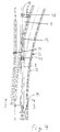
- Fig. 2 shows the schematic structure of a particularly preferred Switch according to the invention in supervision in the switch position straight drive and the adjacent routes under supervision.
- the switch according to the invention consists of the rotating segment 1, the left switch tongue B and the right switch tongue A.
- the rotating segment 1 has the right rail Pointing to the left 11 and the left rail of the Switch position to the right 12.
- the right rail of the switch to the left 11 the top straight rail C.
- the left rail of the The switch position to the right 12 is with its outside the outside of the right rail according to the switch position left 11 set at right angles.
- the rotating segment is 1 with bearings 40 and advantageously also with one or several intermediate stores 41 stored.
- the left switch tongue B the left rail of the switch position points to the left 31 and the pivot bearing 34
- the right switch tongue A the right rail of the switch to the right 32 and that Has pivot bearing 33. Determining the exact location of the Bearing 40, intermediate bearing 41 and pivot bearing 33, 34 for one collision-free kinematics must adhere to the contour of the route as well as the turnout radius.
- the guidance in The right rail is set by the left rail of the Pointing to the left 31 and the right rail of the Setting the course to the left 11.
- the electric motor with gear M advantageously causes the rotary movement of the rotary segment 1.
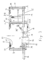
- the section A-A is shown in FIG. 3.
- the rotating segment 1 has one Rotary beam 18, a rail support 17, one in supervision straight rail C and a rail D bent under supervision.
- the rotary bar 18 is rotatably mounted about the axis of rotation 19.
- At one end of the rotating beam 18 is one end of the rail support Carrier 17 attached.
- the rail C which is straight under supervision, is fastened, the right rail in the present embodiment the turnout to the left is 11.
- On the outside of the straight C under supervision is the outside of the under supervision curved rail D attached at right angles, which in present embodiment, the left rail of the Turning to the right is 12.
- the rotating segment 1 has advantageously a mass balance 16 and is with Connecting rods 14, 15 so with the switch tongues A, B coupled that this with the rotation of the rotating segment 1 of one end position in the other end position in their for the respective Switch position swung in or out desired position become.
- the switch tongue B is swung in and the switch tongue A swung out.
- the switch tongues A, B are advantageously guided in the linear guides 35, 36.
- the Lock 26 is advantageously so on the rotating segment 1 mounted that they from the rotary movement of the rotating segment 1 the switch tongue B locked after it has been swung in is.
- the rotating segment 1 is straight in the switch position Advantageously drive with its rotating beam 18 on the Support 21, which advantageously contains the lock 23.
- Fig. 4 shows the switch from Fig. 2 branching in the switch position Ride under supervision.
- the rotating segment 1 is 90 ° around the Rotation axis 19 rotated so that the left rail of the switch position to the right 12 the left lane guidance and the right one Rail of the switch position to the right 32 of the switch tongue A the right lane takes over.
- the switch tongue B is swung out.
- the section B-B from FIG. 4 is shown in FIG. 5.
- the switch tongue A is pivoted in and preferably with the lock 25 secured.
- the lock 25 is advantageously on the rotating segment 1 mounted that they from the rotational movement of the Turning segment 1 locks the switch tongue A after this is swung in.
- the rotating segment 1 is in this position with the rail support 17 on the support 22, which advantageously the lock 24 contains.
- the switch described above shows the the switch DE-OS 38 33 904 already known continues better tracking of the vehicles because the Side guide rails 81 and horizontal guide rails 82 den cover the entire turnout area and switch points A, B can be better assigned to the route than the individual Rotating segments of the cited scripture.
- By coupling the Rotating segment 1 and the switch tongues A, B also result overall simpler movements, since only the rotating segment 1 must be rotated by 90 °.
Landscapes
- Engineering & Computer Science (AREA)
- Mechanical Engineering (AREA)
- Architecture (AREA)
- Civil Engineering (AREA)
- Structural Engineering (AREA)
- Train Traffic Observation, Control, And Security (AREA)
- Linear Motors (AREA)
- Control Of Vehicles With Linear Motors And Vehicles That Are Magnetically Levitated (AREA)
- Railway Tracks (AREA)
Description
- Fig. 1
- einen Fahrweg und ein spurgeführtes Fahrzeug mit Linearmotorantrieb im Querschnitt,
- Fig. 2
- den schematischen Aufbau einer besonders bevorzugten erfindungsgemäßen Weiche in Weichenstellung gerade Fahrt in Aufsicht,
- Fig. 3
- den Schnitt A-A aus Fig. 2,
- Fig. 4
- den schematischen Aufbau der besonders bevorzugten erfindungsgemäßen Weiche aus Fig. 2 in Weichenstellung abzweigende Fahrt in Aufsicht,
- Fig. 5
- den Schnitt B-B aus Fig. 4.
Claims (9)
- Weiche für Fahrwege von spurgeführten Fahrzeugen mit Linearmotorantrieb, die einen Fahrweg je nach Weichenstellung mit einem linken oder rechten Fahrweg verbindet, wobei die Fahrwege rechte und linke Schienen (8) - vom vereinigten spitzen Weichenende zum gegabelten Weichenende aus gesehen - aufweisen und die Schienen (8) jeweils mit Statoren (83), Seitenführungsschienen (81) für Seitenführungsrollen der Fahrzeuge und mit Horizontalführungsschienen (82) für Vertikalführungsrollen (92) der Fahrzeuge versehen sind und wobei die rechten und linken Schienen der Weichen zum Umstellen der Weichen ausgetauscht werden,
dadurch gekennzeichnet, daß die rechte Schiene der Weichenstellung nach links (11) und die linke Schiene der Weichenstellung nach rechts (12) zu einem Drehsegment (1) zusammengefaßt sind, das durch Drehung um 90° die für die jeweilige Weichenstellung erforderliche Schiene in die richtige Position bringt, und
daß die linke Schiene der Weichenstellung nach links (31) und die rechte Schiene der Weichenstellung nach rechts (32) als Weichenzungen (B, A) ausgeführt sind und zur jeweiligen Weichenstellung einschwenkbar sind. - Weiche nach Anspruch 1, dadurch gekennzeichnet,daß das Drehsegment (1) Drehbalken (18), Schienenträger (17), die rechte Schiene der Weichenstellung nach links (11) und die linke Schiene der Weichenstellung nach rechts (12) aufweist,daß die Drehbalken (18) um die Drehachse (19) drehbar gelagert sind und an den einen Enden der Drehbalken (18) die einen Enden der Schienenträger (17) im rechten Winkel befestigt sind,daß die rechte Schiene der Weichenstellung nach links (11) und die linke Schiene der Weichenstellung nach rechts (12) an ihren Außenseiten im rechten Winkel zueinander zusammengefügt sind und eine der beiden Schienen auf den anderen Enden der Schienenträger (17) aufgesetzt ist.
- Weiche nach Anspruch 2, dadurch gekennzeichnet, daß an den anderen Enden der Schienenträger (17) die in Aufsicht gerade Schiene (C) aufgesetzt ist und daß an deren Außenseite die in Aufsicht gebogene Schiene (D) im rechten Winkel angesetzt ist.
- Weiche nach Anspruch 2 oder 3, dadurch gekennzeichnet, daß das Drehsegment (1) in den Endlagen auf Auflagern (21, 22) aufliegt.
- Weiche nach Anspruch 4, dadurch gekennzeichnet, daß das Drehsegment (1) und die Weichenzungen (A, B) in ihren Endlagen Verriegelungen (23, 24, 25, 26) aufweisen.
- Weiche nach einem der vorstehenden Ansprüche, dadurch gekennzeichnet, daß das Drehsegment (1) und die Weichenzungen (A, B) mit Verbindungsstangen (14, 15) so gekoppelt sind, daß sie mit einem einzigen Antrieb verstellbar sind.
- Weiche nach Anspruch 5, 6 oder 7, dadurch gekennzeichnet, daß die Verriegelungen (23, 24, 25, 26) Überwachungseinrichtungen aufweisen.
- Weiche nach einem der Ansprüche 2 - 7, dadurch gekennzeichnet, daß der Drehbalken (18) über den Drehpunkt (19) hinaus verlängert ist und einen Masseausgleich (16) aufweist.
- Weiche nach einem der vorstehenden Ansprüche, dadurch gekennzeichnet, daß ein Elektromotor mit Getriebe (M) als Weichenantrieb vorgesehen ist.
Applications Claiming Priority (2)
| Application Number | Priority Date | Filing Date | Title |
|---|---|---|---|
| DE4343395A DE4343395A1 (de) | 1993-12-18 | 1993-12-18 | Weiche für Fahrwege von spurgeführten Fahrzeugen mit Linearmotorantrieb |
| DE4343395 | 1993-12-18 |
Publications (2)
| Publication Number | Publication Date |
|---|---|
| EP0658652A1 EP0658652A1 (de) | 1995-06-21 |
| EP0658652B1 true EP0658652B1 (de) | 1999-03-24 |
Family
ID=6505474
Family Applications (1)
| Application Number | Title | Priority Date | Filing Date |
|---|---|---|---|
| EP94119870A Expired - Lifetime EP0658652B1 (de) | 1993-12-18 | 1994-12-15 | Weiche für Fahrwege von spurgeführten Fahrzeugen mit Linearmotorantrieb |
Country Status (4)
| Country | Link |
|---|---|
| US (1) | US5499583A (de) |
| EP (1) | EP0658652B1 (de) |
| JP (1) | JPH07197402A (de) |
| DE (2) | DE4343395A1 (de) |
Families Citing this family (21)
| Publication number | Priority date | Publication date | Assignee | Title |
|---|---|---|---|---|
| AU2948697A (en) * | 1996-04-18 | 1997-11-12 | Siemens Aktiengesellschaft | Power supply for a longitudinal stator drive |
| DE19619866C2 (de) * | 1996-05-17 | 2003-10-02 | Boegl Max Bauunternehmung Gmbh | Fahrweg für Magnetbahnzüge |
| AT404743B (de) * | 1996-12-23 | 1999-02-25 | Vae Ag | Kurvenzug einer weiche sowie gleisverbindung unter verwendung eines derartigen kurvenzuges |
| US6273000B1 (en) | 1999-05-20 | 2001-08-14 | Aerobus International, Inc. | Rail switching system |
| DE102005009038B4 (de) * | 2005-02-21 | 2007-01-18 | Siemens Ag | Abzweigung für Fahrbahnen von Fahrzeugen, insbesondere von Magnetschwebebahnen |
| US7751952B2 (en) * | 2005-12-30 | 2010-07-06 | Canadian National Railway Company | System and method for computing rail car switching solutions in a switchyard including logic to re-switch cars for arrival rate |
| US7742849B2 (en) * | 2005-12-30 | 2010-06-22 | Canadian National Railway Company | System and method for computing car switching solutions in a switchyard using car ETA as a factor |
| US20070179688A1 (en) * | 2005-12-30 | 2007-08-02 | Canadian National Railway Company | System and method for computing rail car switching solutions in a switchyard |
| US7657348B2 (en) * | 2005-12-30 | 2010-02-02 | Canadian National Railway Company | System and method for computing rail car switching solutions using dynamic classification track allocation |
| US20070156298A1 (en) * | 2005-12-30 | 2007-07-05 | Canadian National Railway Company | System and method for computing rail car switching solutions by assessing space availability in a classification track on the basis of arrival profile |
| US7742848B2 (en) * | 2005-12-30 | 2010-06-22 | Canadian National Railway Company | System and method for computing rail car switching solutions in a switchyard including logic to re-switch cars for block pull time |
| US8060263B2 (en) | 2005-12-30 | 2011-11-15 | Canadian National Railway Company | System and method for forecasting the composition of an outbound train in a switchyard |
| US7747362B2 (en) * | 2005-12-30 | 2010-06-29 | Canadian National Railway Company | System and method for computing rail car switching solutions by assessing space availability in a classification track on the basis of block pull time |
| US7818101B2 (en) * | 2005-12-30 | 2010-10-19 | Canadian National Railway Company | System and method for computing rail car switching solutions in a switchyard using an iterative method |
| US8055397B2 (en) | 2005-12-30 | 2011-11-08 | Canadian National Railway Company | System and method for computing rail car switching sequence in a switchyard |
| US7792616B2 (en) * | 2005-12-30 | 2010-09-07 | Canadian National Railway Company | System and method for computing rail car switching solutions in a switchyard including logic to re-switch cars for block size |
| US20090114775A1 (en) * | 2006-05-24 | 2009-05-07 | Siemens Aktiengesellschaft | Junction for Guideways of Vehicles, in Particular of Magnetic Levitation Railways |
| US8020493B2 (en) * | 2008-12-29 | 2011-09-20 | Universal City Studios Llc | Track-switching device and method |
| AT12662U1 (de) * | 2010-10-18 | 2012-09-15 | Innova Patent Gmbh | Anlage zum bewegen von fahrzeugen längs zweier fahrbahnen |
| WO2019021950A1 (ja) * | 2017-07-26 | 2019-01-31 | 三菱電機株式会社 | 搬送路切替装置及びエレベータ装置 |
| EP3486371B8 (de) * | 2018-10-04 | 2021-07-21 | Spinswitch Technologies, S.L. | Gleisumschalteinheit |
Family Cites Families (8)
| Publication number | Priority date | Publication date | Assignee | Title |
|---|---|---|---|---|
| CH410030A (de) * | 1964-03-20 | 1966-03-31 | Habegger Maschf | Weiche für Bahnen, deren Fahrzeuge die Fahrschienen auf drei Seiten umschliessen, insbesondere Hängebahnen und Einschienenbahnen |
| CH506658A (de) * | 1969-04-17 | 1971-04-30 | Von Roll Ag | Transportanlage |
| US3782291A (en) * | 1972-04-03 | 1974-01-01 | Rohr Industries Inc | Rotatable bridge switch for trackless air cushion vehicle |
| DE2256608C3 (de) * | 1972-11-17 | 1975-12-11 | Siemens Ag, 1000 Berlin Und 8000 Muenchen | Mechanisch stellbare Weiche für eine magnetische Schebebahn |
| US4970967A (en) * | 1988-06-27 | 1990-11-20 | Aeg Westinghouse Transportation Systems, Inc. | Rotary guideway switch for people mover systems |
| US4970965A (en) * | 1988-06-27 | 1990-11-20 | Aeg Westinghouse Transportation Systems, Inc. | Safety locking structure for a rotary guideway switch |
| DE3833904C2 (de) * | 1988-10-05 | 1994-06-23 | Magnetbahn Gmbh | Weiche für Fahrzeug-Spurführungsanlagen, insbesondere Magnetschwebebahn-Spurführungsanlagen |
| DE9302337U1 (de) * | 1993-02-18 | 1993-07-22 | Siemens AG, 80333 München | Weiche für eine Stückgutverteilanlage |
-
1993
- 1993-12-18 DE DE4343395A patent/DE4343395A1/de not_active Withdrawn
-
1994
- 1994-12-15 EP EP94119870A patent/EP0658652B1/de not_active Expired - Lifetime
- 1994-12-15 DE DE59408000T patent/DE59408000D1/de not_active Expired - Fee Related
- 1994-12-16 US US08/358,164 patent/US5499583A/en not_active Expired - Fee Related
- 1994-12-19 JP JP6315113A patent/JPH07197402A/ja active Pending
Also Published As
| Publication number | Publication date |
|---|---|
| US5499583A (en) | 1996-03-19 |
| EP0658652A1 (de) | 1995-06-21 |
| JPH07197402A (ja) | 1995-08-01 |
| DE4343395A1 (de) | 1995-06-22 |
| DE59408000D1 (de) | 1999-04-29 |
Similar Documents
| Publication | Publication Date | Title |
|---|---|---|
| DE4343395A1 (de) | Weiche für Fahrwege von spurgeführten Fahrzeugen mit Linearmotorantrieb | |
| AT216565B (de) | Zungenweiche für Einschienenstandbahnen | |
| DE3833904C2 (de) | Weiche für Fahrzeug-Spurführungsanlagen, insbesondere Magnetschwebebahn-Spurführungsanlagen | |
| DE102010021594B4 (de) | Schienensystem, insbesondere für eine Elektro-Palettenbahn | |
| DE3001450A1 (de) | Volksbelustigungseinrichtung | |
| DE2243910B2 (de) | Schienenfahrzeug mit um senkrechte achsen drehbaren fuehrungsrollen | |
| EP0917600B1 (de) | Überleitverbindung für fahrwegumgreifende spurgeführte fahrzeuge | |
| EP0185973B1 (de) | Gleisführung für ein Fahrgäste aufnehmendes Fahrzeug eines Hochfahrgeschäftes | |
| DE2617780A1 (de) | Bestandteil eines auf einem schienenweg laufenden fahrzeuges | |
| DE19709034C1 (de) | Containertransportsystem mit Schienen | |
| DE4025313A1 (de) | Transportsystem angetrieben durch einen linearmotor | |
| EP1047840A1 (de) | Spurwechseleinrichtung für fahrwege einer magnetschwebebahn | |
| DE2429887A1 (de) | Fahrspurgebundenes fahrzeug, insbesondere kleinkabinenbahn | |
| DE2819068C3 (de) | Vorrichtung zur Steuerung von Weichen bei einer Hängebahn mit Fahrwerken | |
| DE2256608B2 (de) | ||
| DE3134203C2 (de) | Weiche für eine doppelläufige Hängebahn mit beidseitig angeordneten Fahrzeugen | |
| DE3303062C2 (de) | ||
| DE102020001056B3 (de) | Passive weiche für einschienenbahn und einschienenbahn | |
| DE112005002323T5 (de) | Ebenes Terminal für ein spurgeführtes Verkehrssystem | |
| AT410108B (de) | Transportanlage | |
| DE1223861B (de) | Weiche fuer Schienenbahnen | |
| DE895464C (de) | Elektromotorisch betriebenes schienenloses Fahrzeug mit einem an einer elektrischen Oberleitung schleifenden Kontaktarm, welcher die Lenk-einrichtung der Fahrzeugraeder mittels einer mit ihm verbundenen Steuereinrichtung zwanglaeufig nach der durch die Oberleitung angegebenen Richtung steuert | |
| DE2911067A1 (de) | Geleise mit weiche fuer selbstangetriebene fahrzeuge | |
| DD247133A3 (de) | Weiche fuer einschienenhaengebahn | |
| EP0629255B1 (de) | Mechanischer antrieb eines ablagesystems |
Legal Events
| Date | Code | Title | Description |
|---|---|---|---|
| PUAI | Public reference made under article 153(3) epc to a published international application that has entered the european phase |
Free format text: ORIGINAL CODE: 0009012 |
|
| AK | Designated contracting states |
Kind code of ref document: A1 Designated state(s): DE FR GB IT |
|
| 17P | Request for examination filed |
Effective date: 19951214 |
|
| 17Q | First examination report despatched |
Effective date: 19970619 |
|
| GRAG | Despatch of communication of intention to grant |
Free format text: ORIGINAL CODE: EPIDOS AGRA |
|
| GRAG | Despatch of communication of intention to grant |
Free format text: ORIGINAL CODE: EPIDOS AGRA |
|
| GRAH | Despatch of communication of intention to grant a patent |
Free format text: ORIGINAL CODE: EPIDOS IGRA |
|
| GRAH | Despatch of communication of intention to grant a patent |
Free format text: ORIGINAL CODE: EPIDOS IGRA |
|
| GRAA | (expected) grant |
Free format text: ORIGINAL CODE: 0009210 |
|
| AK | Designated contracting states |
Kind code of ref document: B1 Designated state(s): DE FR GB IT |
|
| PG25 | Lapsed in a contracting state [announced via postgrant information from national office to epo] |
Ref country code: IT Free format text: LAPSE BECAUSE OF FAILURE TO SUBMIT A TRANSLATION OF THE DESCRIPTION OR TO PAY THE FEE WITHIN THE PRE;WARNING: LAPSES OF ITALIAN PATENTS WITH EFFECTIVE DATE BEFORE 2007 MAY HAVE OCCURRED AT ANY TIME BEFORE 2007. THE CORRECT EFFECTIVE DATE MAY BE DIFFERENT FROM THE ONE RECORDED.SCRIBED TIME-LIMIT Effective date: 19990324 Ref country code: GB Free format text: LAPSE BECAUSE OF NON-PAYMENT OF DUE FEES Effective date: 19990324 Ref country code: FR Free format text: LAPSE BECAUSE OF FAILURE TO SUBMIT A TRANSLATION OF THE DESCRIPTION OR TO PAY THE FEE WITHIN THE PRESCRIBED TIME-LIMIT Effective date: 19990324 |
|
| REF | Corresponds to: |
Ref document number: 59408000 Country of ref document: DE Date of ref document: 19990429 |
|
| EN | Fr: translation not filed | ||
| GBV | Gb: ep patent (uk) treated as always having been void in accordance with gb section 77(7)/1977 [no translation filed] |
Effective date: 19990324 |
|
| PLBE | No opposition filed within time limit |
Free format text: ORIGINAL CODE: 0009261 |
|
| STAA | Information on the status of an ep patent application or granted ep patent |
Free format text: STATUS: NO OPPOSITION FILED WITHIN TIME LIMIT |
|
| 26N | No opposition filed | ||
| PGFP | Annual fee paid to national office [announced via postgrant information from national office to epo] |
Ref country code: DE Payment date: 20020603 Year of fee payment: 8 |
|
| PG25 | Lapsed in a contracting state [announced via postgrant information from national office to epo] |
Ref country code: DE Free format text: LAPSE BECAUSE OF NON-PAYMENT OF DUE FEES Effective date: 20030701 |