EP0655792B1 - Verfahren zur Herstellung von positiven Platten für Batterien, danach hergestellte Platten und Batterien, die solche Platten verwenden. - Google Patents
Verfahren zur Herstellung von positiven Platten für Batterien, danach hergestellte Platten und Batterien, die solche Platten verwenden. Download PDFInfo
- Publication number
- EP0655792B1 EP0655792B1 EP94304475A EP94304475A EP0655792B1 EP 0655792 B1 EP0655792 B1 EP 0655792B1 EP 94304475 A EP94304475 A EP 94304475A EP 94304475 A EP94304475 A EP 94304475A EP 0655792 B1 EP0655792 B1 EP 0655792B1
- Authority
- EP
- European Patent Office
- Prior art keywords
- strip
- positive
- grid
- alloy
- paste
- Prior art date
- Legal status (The legal status is an assumption and is not a legal conclusion. Google has not performed a legal analysis and makes no representation as to the accuracy of the status listed.)
- Expired - Lifetime
Links
- 238000004519 manufacturing process Methods 0.000 title description 35
- 229910045601 alloy Inorganic materials 0.000 claims abstract description 118
- 239000000956 alloy Substances 0.000 claims abstract description 118
- 229910052791 calcium Inorganic materials 0.000 claims abstract description 38
- 239000011575 calcium Substances 0.000 claims abstract description 38
- OYPRJOBELJOOCE-UHFFFAOYSA-N Calcium Chemical compound [Ca] OYPRJOBELJOOCE-UHFFFAOYSA-N 0.000 claims abstract description 33
- 239000002253 acid Substances 0.000 claims abstract description 25
- ATJFFYVFTNAWJD-UHFFFAOYSA-N Tin Chemical compound [Sn] ATJFFYVFTNAWJD-UHFFFAOYSA-N 0.000 claims abstract description 21
- 229910052709 silver Inorganic materials 0.000 claims abstract description 15
- 239000004332 silver Substances 0.000 claims abstract description 15
- 238000011437 continuous method Methods 0.000 claims abstract description 8
- 238000000034 method Methods 0.000 claims description 59
- KEQXNNJHMWSZHK-UHFFFAOYSA-L 1,3,2,4$l^{2}-dioxathiaplumbetane 2,2-dioxide Chemical compound [Pb+2].[O-]S([O-])(=O)=O KEQXNNJHMWSZHK-UHFFFAOYSA-L 0.000 claims description 15
- 239000011149 active material Substances 0.000 claims description 14
- 230000002745 absorbent Effects 0.000 claims description 12
- 239000002250 absorbent Substances 0.000 claims description 12
- 239000013078 crystal Substances 0.000 claims description 12
- 239000007774 positive electrode material Substances 0.000 claims description 11
- 229920001732 Lignosulfonate Polymers 0.000 claims description 10
- 239000003792 electrolyte Substances 0.000 claims description 9
- 239000000463 material Substances 0.000 claims description 7
- 238000011161 development Methods 0.000 claims description 5
- 229910052712 strontium Inorganic materials 0.000 abstract 2
- CIOAGBVUUVVLOB-UHFFFAOYSA-N strontium atom Chemical compound [Sr] CIOAGBVUUVVLOB-UHFFFAOYSA-N 0.000 abstract 2
- 230000007797 corrosion Effects 0.000 description 46
- 238000005260 corrosion Methods 0.000 description 46
- 239000000203 mixture Substances 0.000 description 30
- 230000005484 gravity Effects 0.000 description 23
- 229910052751 metal Inorganic materials 0.000 description 22
- 239000002184 metal Substances 0.000 description 22
- 238000005266 casting Methods 0.000 description 20
- 229910052718 tin Inorganic materials 0.000 description 20
- 239000001999 grid alloy Substances 0.000 description 19
- 238000013461 design Methods 0.000 description 14
- BQCADISMDOOEFD-UHFFFAOYSA-N Silver Chemical compound [Ag] BQCADISMDOOEFD-UHFFFAOYSA-N 0.000 description 12
- 230000008901 benefit Effects 0.000 description 10
- 238000012360 testing method Methods 0.000 description 9
- 238000006243 chemical reaction Methods 0.000 description 8
- XLYOFNOQVPJJNP-UHFFFAOYSA-N water Substances O XLYOFNOQVPJJNP-UHFFFAOYSA-N 0.000 description 8
- 229910000978 Pb alloy Inorganic materials 0.000 description 7
- YBOXAZZJNODWJE-UHFFFAOYSA-N [Pb].[Sn].[Ca] Chemical compound [Pb].[Sn].[Ca] YBOXAZZJNODWJE-UHFFFAOYSA-N 0.000 description 7
- 238000001035 drying Methods 0.000 description 7
- 230000015556 catabolic process Effects 0.000 description 6
- 238000006731 degradation reaction Methods 0.000 description 6
- 230000008569 process Effects 0.000 description 6
- 238000012545 processing Methods 0.000 description 6
- 229910001174 tin-lead alloy Inorganic materials 0.000 description 6
- 208000032953 Device battery issue Diseases 0.000 description 5
- 229910052782 aluminium Inorganic materials 0.000 description 5
- XAGFODPZIPBFFR-UHFFFAOYSA-N aluminium Chemical compound [Al] XAGFODPZIPBFFR-UHFFFAOYSA-N 0.000 description 5
- 229910052787 antimony Inorganic materials 0.000 description 5
- WATWJIUSRGPENY-UHFFFAOYSA-N antimony atom Chemical compound [Sb] WATWJIUSRGPENY-UHFFFAOYSA-N 0.000 description 5
- 239000000428 dust Substances 0.000 description 5
- 230000015572 biosynthetic process Effects 0.000 description 4
- 238000005097 cold rolling Methods 0.000 description 4
- 230000007613 environmental effect Effects 0.000 description 4
- 230000002028 premature Effects 0.000 description 4
- 239000004135 Bone phosphate Substances 0.000 description 3
- 238000010924 continuous production Methods 0.000 description 3
- 230000009977 dual effect Effects 0.000 description 3
- 239000007789 gas Substances 0.000 description 3
- 238000010438 heat treatment Methods 0.000 description 3
- 238000012423 maintenance Methods 0.000 description 3
- 230000001105 regulatory effect Effects 0.000 description 3
- 238000003860 storage Methods 0.000 description 3
- 229910001316 Ag alloy Inorganic materials 0.000 description 2
- 229910000882 Ca alloy Inorganic materials 0.000 description 2
- QAOWNCQODCNURD-UHFFFAOYSA-N Sulfuric acid Chemical compound OS(O)(=O)=O QAOWNCQODCNURD-UHFFFAOYSA-N 0.000 description 2
- YNVQGJXEHIXCDR-UHFFFAOYSA-N [Ag].[Sn].[Ca] Chemical compound [Ag].[Sn].[Ca] YNVQGJXEHIXCDR-UHFFFAOYSA-N 0.000 description 2
- 238000005275 alloying Methods 0.000 description 2
- 238000001816 cooling Methods 0.000 description 2
- 230000003247 decreasing effect Effects 0.000 description 2
- 229910003460 diamond Inorganic materials 0.000 description 2
- 239000010432 diamond Substances 0.000 description 2
- 230000000694 effects Effects 0.000 description 2
- 238000009472 formulation Methods 0.000 description 2
- 230000006870 function Effects 0.000 description 2
- 239000002141 low-antimony alloy Substances 0.000 description 2
- 239000011159 matrix material Substances 0.000 description 2
- 239000004005 microsphere Substances 0.000 description 2
- 238000002156 mixing Methods 0.000 description 2
- 238000012986 modification Methods 0.000 description 2
- 230000004048 modification Effects 0.000 description 2
- 238000001953 recrystallisation Methods 0.000 description 2
- 230000009467 reduction Effects 0.000 description 2
- 238000005096 rolling process Methods 0.000 description 2
- 238000009751 slip forming Methods 0.000 description 2
- 239000003981 vehicle Substances 0.000 description 2
- 238000013022 venting Methods 0.000 description 2
- -1 viz. Substances 0.000 description 2
- RNFJDJUURJAICM-UHFFFAOYSA-N 2,2,4,4,6,6-hexaphenoxy-1,3,5-triaza-2$l^{5},4$l^{5},6$l^{5}-triphosphacyclohexa-1,3,5-triene Chemical compound N=1P(OC=2C=CC=CC=2)(OC=2C=CC=CC=2)=NP(OC=2C=CC=CC=2)(OC=2C=CC=CC=2)=NP=1(OC=1C=CC=CC=1)OC1=CC=CC=C1 RNFJDJUURJAICM-UHFFFAOYSA-N 0.000 description 1
- 229910000838 Al alloy Inorganic materials 0.000 description 1
- 229910052684 Cerium Inorganic materials 0.000 description 1
- MYMOFIZGZYHOMD-UHFFFAOYSA-N Dioxygen Chemical compound O=O MYMOFIZGZYHOMD-UHFFFAOYSA-N 0.000 description 1
- 241000237858 Gastropoda Species 0.000 description 1
- 229910001245 Sb alloy Inorganic materials 0.000 description 1
- 229910020816 Sn Pb Inorganic materials 0.000 description 1
- 229910020922 Sn-Pb Inorganic materials 0.000 description 1
- 229910008783 Sn—Pb Inorganic materials 0.000 description 1
- ULGYAEQHFNJYML-UHFFFAOYSA-N [AlH3].[Ca] Chemical compound [AlH3].[Ca] ULGYAEQHFNJYML-UHFFFAOYSA-N 0.000 description 1
- HSYHTOSSEGHFLW-UHFFFAOYSA-N [Pb].[Se].[Sn].[As].[Sb] Chemical compound [Pb].[Se].[Sn].[As].[Sb] HSYHTOSSEGHFLW-UHFFFAOYSA-N 0.000 description 1
- 230000001154 acute effect Effects 0.000 description 1
- 238000003483 aging Methods 0.000 description 1
- 230000004075 alteration Effects 0.000 description 1
- 229910052924 anglesite Inorganic materials 0.000 description 1
- 230000003466 anti-cipated effect Effects 0.000 description 1
- 239000002140 antimony alloy Substances 0.000 description 1
- QQHJESKHUUVSIC-UHFFFAOYSA-N antimony lead Chemical compound [Sb].[Pb] QQHJESKHUUVSIC-UHFFFAOYSA-N 0.000 description 1
- 238000013459 approach Methods 0.000 description 1
- QVGXLLKOCUKJST-UHFFFAOYSA-N atomic oxygen Chemical compound [O] QVGXLLKOCUKJST-UHFFFAOYSA-N 0.000 description 1
- 230000004888 barrier function Effects 0.000 description 1
- 238000010923 batch production Methods 0.000 description 1
- 230000009286 beneficial effect Effects 0.000 description 1
- GWXLDORMOJMVQZ-UHFFFAOYSA-N cerium Chemical compound [Ce] GWXLDORMOJMVQZ-UHFFFAOYSA-N 0.000 description 1
- 230000008859 change Effects 0.000 description 1
- 230000003749 cleanliness Effects 0.000 description 1
- 239000011248 coating agent Substances 0.000 description 1
- 238000000576 coating method Methods 0.000 description 1
- 239000000470 constituent Substances 0.000 description 1
- 238000010276 construction Methods 0.000 description 1
- 230000001186 cumulative effect Effects 0.000 description 1
- 238000005520 cutting process Methods 0.000 description 1
- 230000001351 cycling effect Effects 0.000 description 1
- 230000001419 dependent effect Effects 0.000 description 1
- 230000003292 diminished effect Effects 0.000 description 1
- 229910001882 dioxygen Inorganic materials 0.000 description 1
- YDEXUEFDPVHGHE-GGMCWBHBSA-L disodium;(2r)-3-(2-hydroxy-3-methoxyphenyl)-2-[2-methoxy-4-(3-sulfonatopropyl)phenoxy]propane-1-sulfonate Chemical compound [Na+].[Na+].COC1=CC=CC(C[C@H](CS([O-])(=O)=O)OC=2C(=CC(CCCS([O-])(=O)=O)=CC=2)OC)=C1O YDEXUEFDPVHGHE-GGMCWBHBSA-L 0.000 description 1
- 238000011049 filling Methods 0.000 description 1
- 239000003063 flame retardant Substances 0.000 description 1
- 230000006872 improvement Effects 0.000 description 1
- 239000004615 ingredient Substances 0.000 description 1
- 238000005304 joining Methods 0.000 description 1
- 229910000464 lead oxide Inorganic materials 0.000 description 1
- 230000003647 oxidation Effects 0.000 description 1
- 238000007254 oxidation reaction Methods 0.000 description 1
- YEXPOXQUZXUXJW-UHFFFAOYSA-N oxolead Chemical compound [Pb]=O YEXPOXQUZXUXJW-UHFFFAOYSA-N 0.000 description 1
- 229910052760 oxygen Inorganic materials 0.000 description 1
- 239000001301 oxygen Substances 0.000 description 1
- 238000011417 postcuring Methods 0.000 description 1
- 238000004080 punching Methods 0.000 description 1
- 239000002994 raw material Substances 0.000 description 1
- 238000005215 recombination Methods 0.000 description 1
- 230000006798 recombination Effects 0.000 description 1
- 238000011160 research Methods 0.000 description 1
- 230000004044 response Effects 0.000 description 1
- 238000000926 separation method Methods 0.000 description 1
- 229920005552 sodium lignosulfonate Polymers 0.000 description 1
- 239000007787 solid Substances 0.000 description 1
- 230000001629 suppression Effects 0.000 description 1
- 238000004347 surface barrier Methods 0.000 description 1
- 238000012546 transfer Methods 0.000 description 1
- 238000005303 weighing Methods 0.000 description 1
- 238000004260 weight control Methods 0.000 description 1
Images

Classifications
-
- H—ELECTRICITY
- H01—ELECTRIC ELEMENTS
- H01M—PROCESSES OR MEANS, e.g. BATTERIES, FOR THE DIRECT CONVERSION OF CHEMICAL ENERGY INTO ELECTRICAL ENERGY
- H01M4/00—Electrodes
- H01M4/02—Electrodes composed of, or comprising, active material
- H01M4/64—Carriers or collectors
- H01M4/82—Multi-step processes for manufacturing carriers for lead-acid accumulators
-
- C—CHEMISTRY; METALLURGY
- C22—METALLURGY; FERROUS OR NON-FERROUS ALLOYS; TREATMENT OF ALLOYS OR NON-FERROUS METALS
- C22C—ALLOYS
- C22C11/00—Alloys based on lead
- C22C11/06—Alloys based on lead with tin as the next major constituent
-
- H—ELECTRICITY
- H01—ELECTRIC ELEMENTS
- H01M—PROCESSES OR MEANS, e.g. BATTERIES, FOR THE DIRECT CONVERSION OF CHEMICAL ENERGY INTO ELECTRICAL ENERGY
- H01M4/00—Electrodes
- H01M4/02—Electrodes composed of, or comprising, active material
- H01M4/14—Electrodes for lead-acid accumulators
- H01M4/16—Processes of manufacture
- H01M4/20—Processes of manufacture of pasted electrodes
-
- H—ELECTRICITY
- H01—ELECTRIC ELEMENTS
- H01M—PROCESSES OR MEANS, e.g. BATTERIES, FOR THE DIRECT CONVERSION OF CHEMICAL ENERGY INTO ELECTRICAL ENERGY
- H01M4/00—Electrodes
- H01M4/02—Electrodes composed of, or comprising, active material
- H01M4/62—Selection of inactive substances as ingredients for active masses, e.g. binders, fillers
- H01M4/627—Expanders for lead-acid accumulators
-
- H—ELECTRICITY
- H01—ELECTRIC ELEMENTS
- H01M—PROCESSES OR MEANS, e.g. BATTERIES, FOR THE DIRECT CONVERSION OF CHEMICAL ENERGY INTO ELECTRICAL ENERGY
- H01M4/00—Electrodes
- H01M4/02—Electrodes composed of, or comprising, active material
- H01M4/64—Carriers or collectors
- H01M4/66—Selection of materials
- H01M4/68—Selection of materials for use in lead-acid accumulators
- H01M4/685—Lead alloys
-
- H—ELECTRICITY
- H01—ELECTRIC ELEMENTS
- H01M—PROCESSES OR MEANS, e.g. BATTERIES, FOR THE DIRECT CONVERSION OF CHEMICAL ENERGY INTO ELECTRICAL ENERGY
- H01M4/00—Electrodes
- H01M4/02—Electrodes composed of, or comprising, active material
- H01M4/64—Carriers or collectors
- H01M4/70—Carriers or collectors characterised by shape or form
- H01M4/72—Grids
- H01M4/73—Grids for lead-acid accumulators, e.g. frame plates
-
- H—ELECTRICITY
- H01—ELECTRIC ELEMENTS
- H01M—PROCESSES OR MEANS, e.g. BATTERIES, FOR THE DIRECT CONVERSION OF CHEMICAL ENERGY INTO ELECTRICAL ENERGY
- H01M10/00—Secondary cells; Manufacture thereof
- H01M10/34—Gastight accumulators
- H01M10/342—Gastight lead accumulators
-
- H—ELECTRICITY
- H01—ELECTRIC ELEMENTS
- H01M—PROCESSES OR MEANS, e.g. BATTERIES, FOR THE DIRECT CONVERSION OF CHEMICAL ENERGY INTO ELECTRICAL ENERGY
- H01M2220/00—Batteries for particular applications
- H01M2220/20—Batteries in motive systems, e.g. vehicle, ship, plane
-
- Y—GENERAL TAGGING OF NEW TECHNOLOGICAL DEVELOPMENTS; GENERAL TAGGING OF CROSS-SECTIONAL TECHNOLOGIES SPANNING OVER SEVERAL SECTIONS OF THE IPC; TECHNICAL SUBJECTS COVERED BY FORMER USPC CROSS-REFERENCE ART COLLECTIONS [XRACs] AND DIGESTS
- Y02—TECHNOLOGIES OR APPLICATIONS FOR MITIGATION OR ADAPTATION AGAINST CLIMATE CHANGE
- Y02E—REDUCTION OF GREENHOUSE GAS [GHG] EMISSIONS, RELATED TO ENERGY GENERATION, TRANSMISSION OR DISTRIBUTION
- Y02E60/00—Enabling technologies; Technologies with a potential or indirect contribution to GHG emissions mitigation
- Y02E60/10—Energy storage using batteries
-
- Y—GENERAL TAGGING OF NEW TECHNOLOGICAL DEVELOPMENTS; GENERAL TAGGING OF CROSS-SECTIONAL TECHNOLOGIES SPANNING OVER SEVERAL SECTIONS OF THE IPC; TECHNICAL SUBJECTS COVERED BY FORMER USPC CROSS-REFERENCE ART COLLECTIONS [XRACs] AND DIGESTS
- Y02—TECHNOLOGIES OR APPLICATIONS FOR MITIGATION OR ADAPTATION AGAINST CLIMATE CHANGE
- Y02P—CLIMATE CHANGE MITIGATION TECHNOLOGIES IN THE PRODUCTION OR PROCESSING OF GOODS
- Y02P70/00—Climate change mitigation technologies in the production process for final industrial or consumer products
- Y02P70/50—Manufacturing or production processes characterised by the final manufactured product
Definitions
- This invention relates to lead-acid batteries and, more particularly, to grids and plates used in making such batteries and to the method of making such grids and plates.
- the calcium content in such alloys for positive grids has varied generally from about 0.06 to about 0.1% by weight of the alloy while the tin has generally ranged from about 0.1 up to 0.8% and even more. More typically, the calcium content in such alloys when used for making maintenance-free battery grids has been at least about 0.08% by weight or more.
- low antimony lead-based alloys viz., alloys containing antimony contents of about 1 to about 2.5%, more typically about 1.5% or so.
- Use of such low antimony alloys generally required efforts to add other alloying ingredients since such low antimony alloys were not capable of being made into grids at acceptable rates under normal production conditions.
- the positive grids used initially for maintenance-free batteries typically had thicknesses of about 60 to about 70 mils or so.
- the batteries were likewise configured to provide an excess of the electrolyte over that needed to provide the rated capacity of the battery.
- maintenance-free batteries contained, in effect, a reservoir of electrolyte available to replenish the water loss, during the service life of the battery.
- the use of appropriate grid alloys will reduce water loss during the service life of the battery, there will always be some water loss in service. Having an excess of electrolyte by design will compensate for this loss.
- SLI automotive batteries typically used for the starting, lighting and ignition requirements of an automobile
- Battery grids have typically been made by gravity casting (e.g., the hot molten alloy is fed into what is termed a book mold and is then allowed to solidify, the book mold providing two side-by-side grids).
- Production equipment using an alternate method to fabricate grids is now commercially available by which battery grids can be continuously formed by expanded metal fabrication techniques. For example, a rolled or wrought alloy strip or a cast strip is slit and expanded using reciprocating dies or the like and then cut into the desired width and height dimensions to form the grid with a lug.
- the under-the-hood temperature is particularly high in the warmer climates.
- One automobile manufacturer has perceived that, in the past three years or so, the temperature to which an SLI battery is exposed under-the-hood in such warmer climates has risen from about 125°F to about 165°-190°F in new automobiles.
- the specific temperature increase which is involved is not particularly important. What is important is that such under-the-hood temperatures have in fact increased.
- the impact of this increase in the under-the-hood vehicle service temperatures on the failure modes has been to substantially increase the occurrence of premature battery failures.
- the incidence of premature battery failures due to excessive positive grid corrosion has been significant.
- U.S. Patent 2,860,969 to Walsh is directed to the inclusion of cerium as a grain refiner for lead-calcium, lead-tin-calcium and lead-tin-silver-calcium alloys, which alloys can also contain a small amount of aluminum.
- the calcium contents disclosed range from 0.03 to 0.1% with the silver levels exemplified being from 0.1 to 0.5% by weight.
- silver-based calcium-tin-lead positive grid alloys have been utilized in sealed, oxygen gas recombinant valve-regulated lead-acid batteries. Such alloys also contain aluminum in an amount of about 0.02 to 0.03% by weight.
- the calcium content ranges from about 0.09 to about 0.11% by weight while the silver content ranges from about 0.016-0.02% by weight, and the tin content ranges from about 0.5-0.75% by weight.
- battery grids can be continuously cast on a rotary drum grid caster. Additionally, battery grids can also be continuously formed by expanded metal fabrication techniques.
- checking cracks or shrinkage cracks in the cured or dried active material paste on the plates, particularly adjacent to the grid wire surface.
- Such checking cracks can result from either excessive drying or from drying (i.e., moisture removal) too quickly.
- Such checking cracks not only decrease the expected service life but also the low and high rate discharge performance of batteries using plates having checking cracks because of poor paste adhesion to the underlying grid surface.
- Lead dust is a major problem, stemming from loss of powdery active material from cured and dry paste during processing and handling while assembling batteries. Mechanical handling loosens powdery active material since there are no surface barriers. The resulting lead dust must be dealt with in an environmentally satisfactory manner, and production staff have to wear respirators while carrying out pasting and battery assembly operations. Indeed, a great many production safeguards need to be provided to handle powdery lead oxide dust.
- a lead-based grid alloy consisting essentially of lead, calcium in the range of from about 0.02 to 0.05%, tin in the range of from about 0.3 to about 0.5%, and silver in the range of from about 0.02 to about 0.045%, will provide positive grids having enhanced resistance to positive grid corrosion such that they will impart to a maintenance-free battery a useful service life in current automobiles operating with high under-the-hood temperatures even in geographical regions with relatively high ambient conditions.
- EP-0506323 also discloses that a rolled, cast, or wrought strip made of such an alloy can be used to make a positive grid using expanded metal techniques.
- the invention is concerned with providing a continuous method for making lead-acid battery positive plates involving directly casting an alloy strip from a lead-based, calcium-tin-silver alloy having the above-defined composition, converting the cast strip to a battery grid of the desired configuration using expanded metal fabrication techniques and then pasting the battery grid.
- the invention further provides a SLI lead-acid positive plate comprising a grid having a lug, a top bar to which the lug is connected, an expanded grid mesh made from a directly cast strip having a thickness in the range of 0.508 mm to 1.524 mm (0.020 inches to 0.060 inches) and a bottom bar, the expanded grid mesh being connected and positioned between the top and bottom bars, the grid being of a lead-based alloy consisting essentially of lead, from about 0.02 to 0.05% calcium, from about 0.3 to about 0.5% tin, and from about 0.02 to 0.045% silver, the percentages being based upon the weight of the grid, the expanded grid mesh having adhered thereto a positive active material paste which includes a lignosulfonate in an amount of from 0.005% to 0.04% by weight of the unformed paste and which is cured in an environment comprising a temperature of from 79.4°C to 98.9°C (175°F to 210°F) and a relative humidity of at least 95%
- lower paste densities can be desirably used than those densities conventionally used with gravity cast lead alloy positive grids.
- the continuous method of this invention (which involves a continuous production line starting from the strip casting to grid expansion to expanded strip pasting, to parting of pasted plates, to flash drying to remove surface moisture for pasted plate curing), in one of its more preferred aspects, provides the capability of achieving substantial economic and environmental benefits while providing improved battery performance and enhanced product consistency.
- this problem may be even more severe in sealed systems due, inter alia, to the recombination reaction involved which is highly exothermic. Still further, while the use of the present invention is highly advantageous for SLI applications due to the substantial positive grid corrosion problem caused by the relatively high under-the-hood temperatures in automobiles of current design, the present invention may advantageously be utilized in other applications where positive grid corrosion is considered to be a problem.
- the alloys employed in positive grids contain calcium in a range of from about 0.02 to about 0.05%. More particularly, due to losses during strip casting, the actual calcium content in the resulting cast alloy strip will be somewhat less than the as added composition previously noted, e.g., the calcium content in a cast strip may decrease by about 0.015% or so from the added calcium level. It is preferred to maintain the range of the calcium, as added, from about 0.035 to 0.055%, so that the cast strip and subsequent expanded metal grid mesh alloy contains 0.02 to 0.05% by weight.
- One interesting aspect about the alloys of the present invention is that photomicrographs of the cast alloys are considered to indicate no real difference in the microstructures as compared to the microstructures resulting from using high calcium content calcium-tin-lead alloys. It might accordingly be expected that batteries utilizing the alloys of the present invention to form the positive grids would have positive grid corrosion characteristics similar to those of batteries utilizing positive grids formed from the conventional high calcium alloys.
- Batteries utilizing the alloys of the present invention to form the positive battery grids exhibit substantially improved positive grid corrosion resistance characteristics. Such improved corrosion characteristics translate to a significantly longer useful battery service life.
- the tin content of the alloys of the present invention can range from about 0.3 to about 0.5% or so, preferably from 0.4 to 0.5%. In general, the tin content employed will be about 10 times that of the calcium.
- the silver content of the alloys of this invention ranges from about 0.02 to 0.045% based upon the total weight of the alloy composition. It is preferred to maintain the silver content in the range of 0.025 to 0.045%, and, more preferably, from 0.03 to 0.045%.
- the alloys of the present invention may be produced in the conventional manner by adding the alloying constituents in the prescribed amounts to the molten lead and then mixing until the mass is homogeneous.
- the alloys are directly cast into a relatively thin cast strip with thicknesses generally ranging from about 0.508 mm to about 1.524 mm (about 0.020 inches to about 0.060 inches) and then converted into positive battery grids utilizing commercially available equipment in accordance with one desirable aspect of the present invention, as will be more fully described hereinafter.
- the thickness of the strip selected will be dependent, in general, upon the anticipated grid corrosion life and the service life requirements desired for the particular applications.
- Positive battery grids formed using the alloys described herein are characterized by adequate stiffness and age hardening responses so as to provide a grid which has characteristics satisfactory for the subsequent pasting, curing and battery assembly operations which are required.
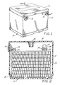
- FIGS. 1 and 2 show a maintenance-free battery utilizing the unique alloy composition of this invention for the positive grids.
- a maintenance-free battery 10 which includes a container 12, a pair of side terminal posts 14 and a cover 16 sealed to the container by any conventional means.
- the container is divided into a plurality of cells, a portion of one cell being shown in FIG. 2; and a battery element is disposed in each of these cells.
- the battery element comprises a plurality of electrodes and separators, one of the positive grids being shown generally at 18.
- the negative grids are of identical or similar construction but are formed with any desired antimony-free alloy.
- the electrode illustrated includes a supporting grid structure 20 having an integral lug 22 and a layer of active material pasted thereto; and a strap 24 joining the lugs 22 of the respective positive and negative grids together.
- Intercell connectors are shown generally at 26 and include a "tombstone" 28 which forms a part of the strap 24.
- the strap 24 may be fused to the grid lugs 22 in assembling the components into an element as is known.
- the terminals 14 are similarly electrically connected through separate straps 24 to the supporting grid structure 20 during assembly, the base of the terminal forming a part of the strap 24.
- Suitable manifold venting systems for allowing evolved gases to escape are shown at 34. Many satisfactory venting systems are well known. In addition, it is believed that all the present maintenance-free batteries manufactured in the United States will typically utilize flame retardant explosion-proof vent designs.
- the particular design configurations of the battery may be varied as desired for the intended application.
- the alloys described herein, and positive grids made using such alloys may be advantageously utilized in any type and size of lead-acid automotive battery.
- the alloys of the present invention and battery grids made therefrom may be advantageously used in dual terminal batteries such as those shown in U.S. Patent 4,645,725.
- the battery of this invention could comprise a top terminal battery.
- the thickness of the positive grids can vary as is desired for a particular service life and a particular desired rated capacity. However, with any given thickness positive grid, the batteries utilizing the alloys of the present invention will impart enhanced positive grid corrosion resistance to the battery in comparison to conventional maintenance-free batteries having positive grids formed from previously used alloys. In general, the grid thickness in the batteries of this invention can desirably vary from about 30 to about 75 mils for most applications. These grid thicknesses should be considered merely exemplary.
- the alloys used for the negative grids can be varied as desired.
- any negative grid alloy can be used that will provide such performance. This will generally involve an antimony-free, lead-based alloy.
- the typical alloys used for forming negative grids include calcium-tin-lead alloys or calcium-aluminum alloys having the following composition: calcium 0.09 to 0.16%, tin 0.15 to 0.55%, and the balance lead or calcium 0.09 to 0.16%, aluminum 0.01 to 0.035% and the balance, lead.
- the alloy for the strap can be any strap alloy that will provide the desired characteristics. Many such alloys are known and have been used. However, to provide desirable service life for the current under-the-hood conditions in the warmer climates, it is preferred to utilize the antimony-arsenic-tin-selenium lead-based alloys described in U.S. 5,169,734 to Rao et al.
- the desired alloy composition When making a positive grid by expanded metal fabrication techniques, the desired alloy composition will be altered somewhat.
- the alloy used in accordance with this invention, will have the following composition: calcium in the range of from about 0.02 to about 0.05% by weight, tin in the range of from about 0.3 to about 0.5% and silver in the range from about 0.02 to 0.045%.
- the alloy composition set forth is that of the grid.
- the composition of the grid has not been found to differ in any significant respect from that of the alloy composition used to make the rolled, cast, or wrought strip from which the grid is made.
- the composition of the as-added alloy composition does not differ from that of the grid itself.
- lead-based alloys of particularly defined composition may be cast into a continuous strip of desired thickness in the range of 0.508 mm to 1.524 mm (0.020 inches to 0.060 inches) and then subsequently converted using expanded metal fabrication techniques to positive grids and plates which exhibit high temperature positive grid corrosion characteristics considered to be essentially the same as those achieved with gravity cast positive plates made with grids of the same alloy composition by an appropriate selection of the manner in which the strip itself is made.
- positive grid corrosion resistance results can be obtained even though photomicrographs of the directly cast strip employed to make the positive plates exhibit the expected orientation of the grain boundaries in the alloy which results from the direct casting process itself. Strong orientation of grains is usually associated with variable corrosion resistance.
- the resulting strip exhibits microstructural stability without any residual stresses present in the matrix or any recrystallization zones present in the cast matrix.
- the inherent high temperature corrosion resistance properties of the alloy are sufficient to overcome the enhanced susceptibility to corrosion of the strip due to its oriented grain boundaries resulting from direct casting, allowing positive grids and plates to be made which exhibit outstanding high temperature positive grid corrosion resistance.
- the continuously cast strip which is cold rolled to the desired thickness exhibits microstructural instability due to residual stresses and recrystallized zones present resulting from the cold rolling or the like. Even using the desired alloy composition does not compensate for the enhanced susceptibility to corrosion from such microstructure instability induced by residual stresses introduced during rolling. Since recrystallization will be nonuniform in the cold rolled strip, corrosion rate differences exist between recrystallized and non-recrystallized (stressed) regions and hence overall corrosion resistance is usually inferior in rolled strip.
- the alloys described herein make it commercially feasible, it is believed for the first time, to utilize a continuously cast strip to make the positive plates while achieving high temperature positive grid corrosion resistance characteristics only previously obtained with gravity cast grids.
- the potential commercial implications are very significant.
- the economic benefits it is believed, should amount to at least ten cents per battery, and, when all other beneficial aspects are considered, should be several times that amount.
- the method of the present invention thus involves, initially, providing an alloy strip directly cast to the desired thickness.
- the thickness of the alloy strip can be varied as is necessary to satisfy the service life and other requirements of the particular application.
- the strip thickness can vary from about 0.508 mm to about 1.524 mm (about 0.020 inches to about 0.060 inches.
- the alloy weight per grid can be significantly less in the method of the present invention while achieving satisfactory performance in service. A significant savings in raw material costs can thus be achieved.
- directly cast refers to a continuous strip that is cast directly from molten lead alloy into the thickness desired for making the positive grids.
- the casting process thus does not include any cold rolling or other reduction in the thickness of the strip from the cast thickness to the thickness desired for making the positive grid.
- excessive cold rolling of the cast strip will significantly diminish the desired high temperature corrosion resistance characteristics of the resulting grids.
- Equipment for making a suitable directly cast alloy continuous strip from molten lead alloy is commercially available (Cominco Ltd., Toronto, Canada).
- This directly cast strip can then be converted by known expanded metal fabrication techniques to achieve a continuous source of an expanded lead-alloy grid mesh strip suitable for conversion into positive lead-acid battery plates.
- these operations involve first expanding into grids and pasting with positive or negative paste and then slitting the moving alloy pasted grid mesh strip to provide, after expansion and other processing, as will be described herein, the desired plate size and lug configurations.
- the continuously cast strip may be, for example, from about 76.2 mm (3 inches) to about 101.6 to 127 mm (4-5 inches) wide, preferably about 101.4 mm (4 inches) wide.
- the strip can be slit and expanded at speeds up to about 30.48 to 45.72 m (100 to 150 feet) per minute or so to make transversely positioned, side-by-side grids with the lugs being located toward the center of the expanded strip.
- the thus-formed grid mesh is then moved into a pasting zone and pasted with positive active material paste to provide positive plates. Further processing can then be carried out as will be discussed hereinafter in connection with the illustrative, preferred embodiment.
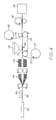
- FIG. 4 thus schematically depicts the various steps and equipment utilized, in the preferred embodiment, of making the positive battery plates of the present invention.
- the equipment utilized comprises a commercially available continuous expanded battery plate production line (Cominco Ltd., Toronto, Canada).
- U.S. 4,315,356 to Why et al. also illustrates, in general, the method and apparatus for forming the expanded mesh strip.
- the strip In utilizing this line, the strip is in the form of coils, each coil weighing about 680.4 kg (1500 pounds).
- Strip 40 from a coil 42 stacked in the horizontal position is continuously fed into the grid expander line. Successive coils can be processed without re-threading by using a strip welder 44 which bonds the end of one coil to the beginning of the next coil.
- Suitable strip welders can achieve the desired bond with cold pressure.
- the grids and plates formed from the strip ends that are bonded together may well have less than optimum high temperature positive grid corrosion resistance. If desired, such grids could be separated out and not used. However, the percentage is so small (e.g., 0.02% of the grids) that separation need not be done.
- the strip 40 is converted into a grid mesh of the desired size and pattern.
- the rotary expansion shown generally at 46, involves an expander tooling module having an assembly of circular cutters mounted onto three shafts which cut and preform the strip 40 into an expandable pattern. Center and outside guide protrusions are also cut into the strip which allows engagement by three sets of silent chains in the expansion section. The outside silent chains diverge, causing the mesh to expand away from the center, forming a diamond pattern. As the mesh is expanded, the outside edges elongate more than the center. A stretcher pulls the center portion forward to match the outside edge.
- Grid mesh flatteners and coining rollers may be employed to roll the grid expanded mesh to the desired thickness (i.e., flattening out any high spots).
- Edge trimmers may be used to remove the outside edges of the mesh so as to provide dimensional uniformity and eliminating any ragged or protruding portions.
- a tab blanker 48 forms the lug and top frame bar configuration of the plate by punching a slug pattern from the center solid strip.
- the mesh strip is thus guided through a rotary male/female die assembly which cuts the slugs and ejects them as salvage.
- a center guide protrusion then is flattened as the grid mesh exits the die set.
- the thus-formed grid mesh strip is continuously moved onto conveyor belt 50 with bottom absorbent paper layer 52 provided from roll 54 being positioned between strip 40 and the surface of the conveyor belt 56.
- Positive active material paste from paste hopper 58 is applied to the desired areas of strip 40 in the pasting zone shown generally at 60.
- Suitable paste-applying apparatus for expanded mesh is known and may be used. As an illustrative example, a suitable paste-applying apparatus is Auto Mac 170 Paster (MAC Engineering, Benton Harbor, Michigan).
- the density of the positive active material paste is somewhat lower than is believed is conventionally used with SLI positive plates made from gravity cast grids.
- the advantages associated with utilizing such lower density positive active material pastes are considerable and include higher active material efficiency and higher cranking power density and material cost savings.
- the dry unformed positive paste density employed varies from about 3.7 to 4.15 gms./cm. 3 in contrast to the range of 3.9-4.20 gms./cm. 3 used with gravity cast grids.
- Such paste densities can be achieved be mixing together with sulfuric acid to provide 14-18% PbSO 4 and from 15-18% water by weight.
- a positive paste composition is utilized which, after curing, results in predominantly tetrabasic lead sulfate modulated crystal size so as to provide an interlocking type of network that will provide enhanced paste adhesion characteristics.
- Typical used curing conditions that enhance the formation of tetrabasic lead sulfate also lead to relatively large crystals being formed which are undesirable as regards active material formation conversion characteristics.
- carefully selected amounts of lignosulfonates sometime used as negative paste expanders will modulate the size of the tetrabasic lead sulfate crystals being formed, at least minimizing the crystal size that would otherwise have resulted.
- Representative samples of useful lignosulfonates include sodium lignosulfonate and the like ("Vanisperse” A and B and "Maracell” XC or XE being specific useful examples). Any lignosulfonate can be employed that functions to desirably modulate the size of the tetrabasic lead sulfate crystal being formed as discussed herein. The amount of lignosulfonate must be carefully selected since excessive amounts will suppress the conversion of tribasic to tetrabasic lead sulfate in the curing.
- lignosulfonate In contrast to the levels used in negative plates (e.g., 0.25-0.5% by weight of the unformed paste), it has been found suitable to use lignosulfonate to about 0.035% by weight of the unformed positive active material paste. Levels of from about 0.005% to about 0.04% are considered illustrative of a useful range. The upper limit desirable in a particular application can be readily determined simply by checking to ascertain whether undue suppression of conversion of tribasic to tetrabasic lead sulfate results. It is believed that even as low an amount as 0.05% of the lignosulfonate used (based upon the weight of the unformed paste) may be excessive in some situations.
- a top absorbent layer of paper is positioned on the upper pasted surface of the pasted plates so as to shroud the pasted plates, the pasted plates being thus sandwiched between the top and bottom absorbent layers.
- any environmental concerns due to lead dust or the like getting into the air should be minimized or generally eliminated because the active material is virtually encapsulated between the paper layers.
- the top absorbent layer of paper functions to simplify any surface drying of the paste required which enhances the consistency of the electrical performance and service life that will be achieved since active material checking and shrinkage cracks next to the grid wires is minimized. Also, when separated into individual plates and stacked, the absorbent paper layer shroud minimizes any sticking problems between adjacent plates in the stack. The paper layer also helps in keeping the plate divider knives clean and sharp.
- absorbent layers a wide variety of materials can be used.
- the principal requirements are wet strength, tensile strength, and electrochemical cleanliness.
- a top absorbent paper layer 62 unwound from roll 44, is fed onto the upper surface 56 of the pasted strip 40.
- the resulting pasted plate sandwich can then be further processed as desired.
- such further processing includes, as in the illustrative preferred embodiment, plate parting (or dividing) and flash drying followed by paste curing, as shown in FIG. 4 at 66 and 68, respectively.
- plate parting or dividing
- flash drying followed by paste curing, as shown in FIG. 4 at 66 and 68, respectively.
- These steps can be carried out in any desired order. However, it is preferred to first carry out the plate parting step because the paper present on either side of the pasted grid mesh prevents the cutters used for plate parting from removing too much paste; and, also, the active material is soft and less susceptible to cutter damage prior to curing.
- Plate parting or dividing employs a rotary cutting die which alternately cuts the pasted grid mesh into left and right plates (viewed from the top).
- the mesh is suitably guided through this step by using an index ring which engages the center lug cut-outs.
- the divided individual plates go through a rapidly moving conveyor where pasted plates are heated to remove a small amount of surface moisture. Typically, 15-20% moisture from the plates is removed in this step.
- the flash-dried plates are stacked in plate trays for further paste curing.
- Curing can be carried out by any of the many known techniques.
- curing of positive pasted plates is carried out by using conditions that favor conversion of tribasic to tetrabasic lead sulfate.
- Such conditions include temperatures of 79.4°C (175°F) up to 98.9°C (210°F) at relative humidities of 95 to 100%.
- Further optional processing steps that could be carried out, if desired, include forced drying of such cured plates at temperatures up to 79.4°C (175°F) and low relative humidity to reduce the free lead content to below 3% and reduce moisture to below 3% level.
- the negative pasted plates, after flash drying, are usually cured at room ambient temperature for up to 72 hours or can be cured at 43.3°C-64.4°C (110°-148°F) and 95% humidity for 24 to 48 hours.
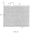
- FIG. 5 illustrates a preferred embodiment of a grid made by expanding metal techniques using a directly cast-sheet and made in accordance with the present invention.
- Grid 70 includes a lug 72, a top bar 74 and a bottom bar 76.
- the mesh design is generally in the form of diamond shapes as indicated at 78.
- the positive plates of this invention may be enveloped with any desired separator. Care should be taken in such process since the grids made by the expanded technique and plates do not include side bars, and the exposed mesh sides or edges thus present a potential problem as regards puncturing the separator if appropriate care is not taken in the enveloping process. For this reason, it is preferred that the negative plates be enveloped. Susceptibility to separator puncture and tear and eventual oxidation of separator and separator failure is much greater at the positive side. This can be greatly minimized by enveloping negative plates.
- the method of the present invention should be capable of making up to about 400 plates/minute or so while achieving significant improved performance in many respects in comparison to what is achieved using gravity cast grids.
- the paste weight, density and thickness are thus more readily controlled, as is the paste adhesion during post-curing so as to minimize checking cracks in the paste. This latter aspect enhances the low and high rate discharge performance as well as the expected service life.
- the resulting grids made by expanded grid fabrication techniques using a direct cast sheet can be heat treated, if desired, to increase the ultimate tensile strength and associated stiffness for facilitating the pasting, stacking and assembly operations.
- Heat treatment of the alloys of the type described herein is well known, as are numerous suitable techniques. As an example, for illustrative purposes, heat treating, after the strip has been cast and prior to subsequent processing, can be accomplished by heating the cast strip at 93.3°C - 104.4°C (200°-220°F) for 150-180 minutes followed by cooling to room temperature.
- This Example compares the life test performance of batteries made with gravity cast positive grids and compares with batteries having positive grids of high calcium content alloys.
- Positive grids were cast from three different alloys using conventional gravity casting methods.
- the cast grids had the following compositions: Alloy 1 (0.029% calcium, 0.49% tin, 0.032% silver and the remainder lead), Alloy 2 (0.045% calcium, 0.48% tin, 0.031 silver and the remainder lead), and Commercial grid alloy (0.1% calcium, 0.62% tin and the remainder lead).
- Batteries using both positive grid designs and the three alloys were built with the same plate count per cell (i.e. - 6 positives and 6 negatives). Other than the difference in the positive grid alloy used, all of the batteries built with each of the two grid designs were identical.
- the batteries built with the thicker grid design (i.e. - the 73J grid) used the constructional parameters set forth in Table 2: Number of plates per cell 12 (6 positive, 6 negative) Positive plate enveloped with 0.027 inch thick Daramic separator (0.686 mm) Positive grid weight 66.0 grams Positive paste weight - unformed 83.1 grams Negative grid weight 32.5 grams Alloy composition of the expanded metal negative grids 0.065% calcium, 0.5% tin, balance-lead Negative paste weight - unformed 67.9 grams
- the batteries built with the thinner grid design i.e. - the 56TS design
- the variation in high temperature performance using the grid alloys of the present invention is considered to reflect minor problems in the manufacturing of the batteries built for testing (i.e.- start-up problems such as bent plates and the like arising from learning how to handle these grids in comparison to the stiffer conventional grids), rather than reflecting any variation in performance due to the alloys used. Eliminating these minor manufacturing problems will allow achieving the consistently superior cycle life and field service by which batteries using the alloys of this invention should be characterized. Regardless of the variation in performance in the battery tested, the batteries made using the positive grid alloys of the present invention provided substantially better high temperature performance than the performance provided by the commercially used positive grid alloy.
- Table 5 shows results obtained with BCI Group 34/78 batteries built using a commercial positive grid alloy (i.e. - 0.10% calcium, 0.66% tin and the remainder lead) in comparison to batteries built using Alloy 3, an alloy according to the present invention (i.e. - the alloy composition of the cast grid was 0.037% calcium, 0.45% tin, 0.032% silver and the balance lead):
- the data in Table 5 supports the view that batteries made with positive grids using the alloy of this invention have such superior performance that similar performance can be obtained even when fewer plates per cell are used and the total plate area is substantially less. Satisfactory performance is obtained even when the battery is discharged at a rate substantially in excess of the rating of the battery (viz. - in Table 5, almost twice the J240 cycle life was provided at 75°C (167°F) even when discharged at 875 amps, which was well over the 625 cold cranking amps rating of the battery).
- the batteries of this invention using the unique positive grid alloys, will provide improved performance as the service life of the battery continues, even when the initial performance may be slightly less than that of a conventional battery (due to the use in the conventional battery of more and thinner plates per cell and more total plate area). More particularly, batteries according to the present invention experience substantially less degradation in performance over the useful service life of a battery in comparison to the performance degradation experienced by conventional batteries.
- Curves A and B show the calculated discharge current in amps to 7.2 amps at 75°C (167°F) as the conventional Group 34/78 dual terminal batteries described in conjunction with Table 5 (i.e., using the commercial positive grid alloy) were discharged, respectively, at 875 amps and 625 amps.
- Curves C and D show the same calculated discharge currents for the Group 34/78 batteries of the present invention also described in conjunction with Table 5, discharged at 875 and 625 amps.
- curves A and C show that the degradation in the discharge current is much less severe for the batteries of the present invention even when discharged at a current (875 amps) well above the rated CCA capacity (625 amps) for the batteries of the present invention.
- curves B and D shows that the batteries of this invention exhibit substantially shallower degradation than is the case with conventional batteries. This substantial improvement in performance by the batteries of this invention will be even more pronounced at lower temperatures.
- This Example shows the use of the present invention to make positive plates from directly cast strips and expanded grid mesh metal techniques and the resulting performance in SLI lead-acid batteries.
- a line similar to that shown in FIG. 4 was used to make positive plates.
- the alloy composition used for the positive plates was as follows: 0.028-0.036% Ca, 0.52% Sn, 0.036% Ag-Pb.
- Negative grids were used having the following composition: 0.065-0.08% Ca, 0.5% Sn-Pb.
- a series of Group 34/78 batteries were made using 14-J type plates per cell. Two groups of batteries were made, one with a 0.737 mm (0.029 inch) strip and the other with a 0.965 mm (0.038 inch)strip. In each group, a subset was made in which a minor apparatus change was made (not considered as effecting the electrical performance). The electrical performance of the batteries was tested and compared to that of similar batteries (except using positive plates gravity cast from an alloy composition of 0.04% Ca, 0.53% Sn, 0.033 Ag). Table 6 sets forth the results.
- a further series of batteries was made in which the positive grids were heat-treated prior to being pasted.
- the heat treating involved heating the cast strip at 205°F for 160 minutes and then cooling to ambient temperature.
- This heat-treated cast strip was then run through the Cominco rotary grid expander machine to make a "J" plate and pasted with positive paste.
- the flash-dried positive plates were cured in a steam chamber at 93.3°C (200°F) for 120 minutes and post cured at ambient temperatures for 3 days before the batteries were assembled.
- the mean grid weight for the positive grids was 40 grams and 33 grams for the negative grids and the unformed active material paste density of the positive plates was 3.92-4.05 g/cc. Table 7 sets forth the results of the electrical performance of these batteries.
- positive grid corrosion characteristics are influenced by open circuit wet storage at ambient temperature conditions.
- the rate of positive grid corrosion is about three times faster under open circuit voltage storage conditions than under regulated voltage controlled charging.
- the battery is on open circuit up to about 90% of the time.
- the positive grid corrosion characteristics of batteries under open circuit storage conditions has a significant impact upon the overall service life performance of a battery.
- the batteries of the present invention exhibit excellent resistance to positive grid corrosion in comparison to that of conventional batteries under open circuit conditions.
- the batteries of the present invention exhibit excellent resistance to positive grid corrosion in comparison to that of conventional batteries under all important conditions where positive grid corrosion is often the prime failure mode.
- This excellent resistance to positive grid corrosion equates to better service performance of the batteries of this invention as the service life of the battery continues due to the greater degradation experienced by conventional batteries.
- this improved performance of the batteries of this invention allows the battery manufacturer a wide range of design choices, allowing the design of excellent cost-efficient batteries for a particular application.
- the battery of this invention described in conjunction with Table 5 utilizes about two pounds of lead less than the conventional batteries described in relation to Table 5.
- a superior performing battery is provided, and the reduced material costs translate to savings substantially larger than the profit margin often available to battery manufacturers.
- the continuous method for making positive plates using a directly cast strip and expanded grids made using the Cominco rotary grid expander which forms one part of this invention offers enormous potential economic benefits.
- certain performance enhancements are achieved as has been previously discussed, while not resulting in any performance degradation in any other respects that is meaningful (e.g., the use of continuously cast alloy strip and grids made by expanded metal techniques may result in a perceptible, but slight, decrease in the cold cranking amps obtained relative to that obtained with gravity cast grids; however, the slight decrease is not considered meaningful).
Landscapes
- Chemical & Material Sciences (AREA)
- Chemical Kinetics & Catalysis (AREA)
- General Chemical & Material Sciences (AREA)
- Electrochemistry (AREA)
- Engineering & Computer Science (AREA)
- Materials Engineering (AREA)
- Mechanical Engineering (AREA)
- Organic Chemistry (AREA)
- Metallurgy (AREA)
- Manufacturing & Machinery (AREA)
- Cell Electrode Carriers And Collectors (AREA)
- Battery Electrode And Active Subsutance (AREA)
- Secondary Cells (AREA)
Claims (7)
- Kontinuierliches Verfahren zum Herstellen von SLI-Bleibatterie-Plusplatten, das umfasst:Bereitstellen eines fallend gegossenen Legierungsbandes mit Dicken im Bereich von 0,508 mm bis 1,524 mm (0,020 Inch bis 0,060 Inch), das gestreckt und zu einer Gitternetzstruktur geschnitten wird, wobei es sich bei dem Legierungsband um eine Legierung auf Bleibasis handelt, die im Wesentlichen aus Blei, von ungefähr 0,02 bis 0,05 % aus Calcium, von ungefähr 0,3 bis 0,5 % aus Zinn und von ungefähr 0,02 bis 0,045 % aus Silber besteht, wobei sich die prozentualen Anteile auf das Gewicht des Legierungsbandes beziehen,kontinuierliches Bewegen des gestreckten Legierungs-Gitternetzbandes in eine Pastierzone,Pastieren des Legierungs-Gittemetzbandes in den gewünschten Bereichen mit positivem aktivem Material, während das Legierungs-Gittemetzband durch die Pastierzone hindurch bewegt wird, um ein pastiertes Plattenband herzustellen,Teilen des so pastierten Platten-Gitternetzbandes in einzelne Plusplatten, undAushärten der pastierten Plusplatten in einer Umgebung, die eine Temperatur im Bereich von 79,4°C bis 98,9°C (175°F bis 210°F) und eine relative Feuchtigkeit von wenigstens 95 % umfasst, um die Entwicklung vierbasiger Bleisulfatkristalle zu fördern, wobei das positive aktive Pastiermaterial ein Lignosulfonat in einer Menge von 0,005 bis 0,04 Gew.-% der ungeformten Paste zum Modulieren der Größe der vierbasigen Bleisulfatkristalle enthält, die beim Aushärten entstehen.
- Verfahren nach Anspruch 1, wobei die Dichte des trockenen ungeformten positiven aktiven Materials im Bereich von 3,7 bis 4,15 Gramm/Kubikzentimeter liegt.
- Verfahren nach Anspruch 1, wobei das Legierungs-Gitternetzband eine Fläche aufweist, auf die die Paste aufgetragen wird, sowie eine Fläche, die der gegenüberliegt, auf die die Paste aufgetragen wird, und wobei eine absorbierende Papierschicht an die Fläche angrenzend angeordnet wird, die der Fläche gegenüberliegt, auf die die Paste aufgetragen wird, bevor das Band in die Pastierzone bewegt wird.
- Verfahren nach Anspruch 1, wobei das Legierungs-Gittemetzband eine Fläche aufweist, auf die die Paste aufgetragen wird, sowie eine Fläche, die der gegenüberliegt, auf die die Paste aufgetragen wird, wobei eine absorbierende Schicht auf der pastierten Fläche des Bandes angeordnet wird, nachdem das Band aus der Pastierzone ausgetreten ist.
- Verfahren nach Anspruch 1, wobei das Legierungs-Gitternetzband eine Fläche aufweist, auf die die Paste aufgetragen wird, sowie eine Fläche, die der gegenüberliegt, auf die die Paste aufgetragen wird, wobei eine absorbierende Schicht an die Fläche angrenzend angeordnet wird, die der Fläche gegenüberliegt, auf die die Paste aufgetragen wird, bevor das Band in die Pastierzone bewegt wird, und eine absorbierende Schicht auf der pastierten Fläche des Bandes angeordnet wird, nachdem das Band aus der Pastierzone ausgetreten ist.
- SLI-Blei-Plusplatte, die ein Gitter mit einem Ansatz, eine obere Leiste, mit der der Ansatz verbunden ist, ein gestrecktes Gitternetz, das aus einem fallend gegossenen Band mit einer Dicke im Bereich von 0,508 mm bis 1,524 mm (0,020 Inch bis 0,060 Inch) hergestellt wird, und eine untere Leiste umfasst, wobei das gestreckte Gitternetz mit der oberen und der unteren Leiste verbunden und zwischen ihnen angeordnet ist und das Gitter aus einer Legierung auf Bleibasis besteht, die im Wesentlichen aus Blei, von ungefähr 0,02 bis 0,05 % aus Calcium, von ungefähr 0,3 bis ungefähr 0,5 % aus Zinn und von ungefähr 0,02 bis 0,045 % aus Silber besteht, wobei sich die prozentualen Anteile auf das Gewicht des Gitters beziehen und an dem gestreckten Gitternetz eine Paste aus positivem aktivem Material haftet, die ein Lignosulfonat in einer Menge von 0,005 bis 0,04 Gew.-% der ungeformten Paste enthält, und die in einer Umgebung ausgehärtet wird, die eine Temperatur von 79,4°C bis 98,9°C (175°F bis 210°F) und eine relative Feuchtigkeit von wenigstens 95 % umfasst, um die Entwicklung vierbasiger Bleisulfatkristalle zu fördem.
- Kraftfahrzeug-SLi-Batterie, die einen Batteriebehälter mit einer Vielzahl von Zellen und ein in den Zellen enthaltenes Elektrolyt umfasst, wobei in jeder Zelle eine Vielzahl positiver und negativer Elektroden angeordnet sind, die eine Gitter-Tragestruktur umfassen, auf die eine Schicht aus aktivem Material pastiert ist, wobei die Gitter-Tragestrukturen für die positiven Elektroden jeweils durch eine SLI-Blei-Plusplatte nach Anspruch 6 gebildet werden.
Applications Claiming Priority (2)
| Application Number | Priority Date | Filing Date | Title |
|---|---|---|---|
| US08/144,688 US5434025A (en) | 1991-03-26 | 1993-10-29 | Battery grids and plates and lead-acid batteries made using such grids and plates |
| US144688 | 2008-06-24 |
Publications (2)
| Publication Number | Publication Date |
|---|---|
| EP0655792A1 EP0655792A1 (de) | 1995-05-31 |
| EP0655792B1 true EP0655792B1 (de) | 2003-01-22 |
Family
ID=22509700
Family Applications (1)
| Application Number | Title | Priority Date | Filing Date |
|---|---|---|---|
| EP94304475A Expired - Lifetime EP0655792B1 (de) | 1993-10-29 | 1994-06-20 | Verfahren zur Herstellung von positiven Platten für Batterien, danach hergestellte Platten und Batterien, die solche Platten verwenden. |
Country Status (9)
| Country | Link |
|---|---|
| US (1) | US5434025A (de) |
| EP (1) | EP0655792B1 (de) |
| JP (1) | JPH07161351A (de) |
| KR (1) | KR100289221B1 (de) |
| AT (1) | ATE231650T1 (de) |
| AU (1) | AU680484B2 (de) |
| CA (1) | CA2124722C (de) |
| DE (1) | DE69432044T2 (de) |
| ES (1) | ES2194021T3 (de) |
Families Citing this family (44)
| Publication number | Priority date | Publication date | Assignee | Title |
|---|---|---|---|---|
| US5874186A (en) * | 1991-03-26 | 1999-02-23 | Gnb Technologies, Inc. | Lead-acid cells and batteries |
| US5851695A (en) | 1992-02-10 | 1998-12-22 | C & D Technologies, Inc. | Recombinant lead-acid cell and long life battery |
| US5650242A (en) * | 1996-01-11 | 1997-07-22 | Gnb Technologies, Inc. | Antimony-arsenic-tin-selenium lead-based strap alloys for lead-acid batteries |
| US6342110B1 (en) * | 1996-03-01 | 2002-01-29 | Integran Technologies Inc. | Lead and lead alloys with enhanced creep and/or intergranular corrosion resistance, especially for lead-acid batteries and electrodes therefor |
| US20020088515A1 (en) * | 1996-03-01 | 2002-07-11 | Aust Karl T. | Thermo-mechanical treated lead and lead alloys especially for current collectors and connectors in lead-acid batteries |
| US5958625A (en) * | 1996-09-23 | 1999-09-28 | Gnb Technologies, Inc. | Positive lead-acid battery grids and cells and batteries using such grids |
| EP0834946B1 (de) * | 1996-10-02 | 2002-09-11 | Japan Storage Battery Company Limited | Ventilgeregelte Blei-Säure-Batterie und Verfahren zu deren Herstellung |
| US5834141A (en) * | 1997-04-18 | 1998-11-10 | Exide Corporation | Positive grid alloys |
| JP3662940B2 (ja) | 1997-05-07 | 2005-06-22 | エグザイド・テクノロジーズ | 鉛蓄電池セル及び陽極プレート及びこれらで使用する合金 |
| US5948566A (en) * | 1997-09-04 | 1999-09-07 | Gnb Technologies, Inc. | Method for making lead-acid grids and cells and batteries using such grids |
| DE19823147A1 (de) * | 1998-05-23 | 1999-11-25 | Vb Autobatterie Gmbh | Elektrodengitter für Bleiakkumulatoren |
| PT969108E (pt) | 1998-06-26 | 2002-11-29 | Vb Autobatterie Gmbh | Ligas para grades de acumuladores |
| US20050112470A1 (en) * | 1998-06-26 | 2005-05-26 | Johnson Controls Technology Company | Alloy for battery grids |
| EP1041164A1 (de) * | 1999-03-27 | 2000-10-04 | Accumulatorenwerke Hoppecke Carl Zoellner & Sohn GmbH & Co. KG | Bleilegierung für die Herstellung von Bleigittern für Akkumulatoren |
| US6274274B1 (en) | 1999-07-09 | 2001-08-14 | Johnson Controls Technology Company | Modification of the shape/surface finish of battery grid wires to improve paste adhesion |
| US6802917B1 (en) * | 2000-05-26 | 2004-10-12 | Integran Technologies Inc. | Perforated current collectors for storage batteries and electrochemical cells, having improved resistance to corrosion |
| NZ524659A (en) * | 2000-08-11 | 2006-03-31 | Exide Technologies | Lead-acid batteries and positive plate and alloys therefor |
| EP1235287A1 (de) * | 2001-02-24 | 2002-08-28 | Accumulatorenwerke Hoppecke Carl Zoellner & Sohn GmbH & Co. KG | Reifung positiver Platten |
| KR100408711B1 (ko) * | 2001-06-04 | 2003-12-11 | 한국타이어 주식회사 | 금 도금층을 포함한 납축전지용 복합 극판 |
| US20020182500A1 (en) * | 2001-06-04 | 2002-12-05 | Enertec Mexico, S. De R.L. De C.V. | Silver-barium lead alloy for lead-acid battery grids |
| US6833218B2 (en) * | 2002-08-23 | 2004-12-21 | Delphi Technologies, Inc. | Direct cast lead alloy strip for expanded metal battery plate grids |
| CN100401935C (zh) * | 2002-10-10 | 2008-07-16 | 陈有孝 | 高寒地区太阳能保温靴 |
| US20040110067A1 (en) * | 2002-12-06 | 2004-06-10 | Johnson Controls Technology Company | Alloy for battery grids |
| JP4505464B2 (ja) * | 2003-10-21 | 2010-07-21 | ジョンソン コントロールズ テクノロジー カンパニー | バッテリーペースト材料および方法 |
| US8021784B2 (en) * | 2004-03-23 | 2011-09-20 | Hammond Group, Inc. | Cureless battery paste and method for producing battery plates |
| US7118830B1 (en) * | 2004-03-23 | 2006-10-10 | Hammond Group, Inc. | Battery paste additive and method for producing battery plates |
| WO2006127575A1 (en) * | 2005-05-23 | 2006-11-30 | Johnson Controls Technology Company | Battery grid |
| JP5183888B2 (ja) * | 2006-01-17 | 2013-04-17 | 古河電池株式会社 | 鉛蓄電池用極板の製造方法 |
| US7704452B2 (en) * | 2006-02-23 | 2010-04-27 | Rsr Technologies, Inc. | Alloy and anode for use in the electrowinning of metals |
| EP2122725B1 (de) | 2007-03-02 | 2014-04-09 | Johnson Controls Technology Company | Negatives batteriegitter |
| US7923155B2 (en) * | 2007-03-20 | 2011-04-12 | Northstar Battery Company, Llc | Lead-tin-silver-bismuth containing alloy for positive grid of lead acid batteries |
| US20080305396A1 (en) * | 2007-06-06 | 2008-12-11 | David Paul Boden | Lead-acid battery expanders with improved life at high temperatures |
| US8533973B2 (en) * | 2008-12-02 | 2013-09-17 | Mac Engineering And Equipment Company, Inc. | Contact flash dryer and method of contact flash drying |
| MX338843B (es) | 2010-03-03 | 2016-05-03 | Johnson Controls Tech Co | Rejillas de bateria y metodos para fabricar las mismas. |
| KR101951453B1 (ko) | 2010-04-14 | 2019-02-22 | 존슨 컨트롤스 테크놀러지 컴퍼니 | 배터리, 배터리 플레이트 조립체 및 조립 방법 |
| US9748578B2 (en) | 2010-04-14 | 2017-08-29 | Johnson Controls Technology Company | Battery and battery plate assembly |
| KR101252631B1 (ko) | 2010-11-08 | 2013-04-09 | 세방전지(주) | 자동차용 배터리 및 극판 제조방법 |
| US9761883B2 (en) | 2011-11-03 | 2017-09-12 | Johnson Controls Technology Company | Battery grid with varied corrosion resistance |
| CN107644978B (zh) * | 2012-03-08 | 2020-12-08 | 阿克爱科蒂夫有限公司 | 改进的铅酸电池结构 |
| DE202013012569U1 (de) | 2013-10-08 | 2017-07-17 | Johnson Controls Autobatterie Gmbh & Co. Kgaa | Gitteranordnung für eine plattenförmige Batterieelektrode eines elektrochemischen Akkumulators sowie Akkumulator |
| CN103700812A (zh) * | 2013-10-15 | 2014-04-02 | 双登集团股份有限公司 | 耐高温深循环铅酸蓄电池 |
| DE102013111667A1 (de) | 2013-10-23 | 2015-04-23 | Johnson Controls Autobatterie Gmbh & Co. Kgaa | Gitteranordnung für eine plattenförmige Batterieelektrode und Akkumulator |
| CA2929792A1 (en) | 2013-11-06 | 2015-05-14 | Northstar Battery Company Llc | Corrosion resistant positive grid for lead-acid batteries |
| CN114798503B (zh) * | 2022-06-07 | 2023-12-08 | 蜂巢能源科技股份有限公司 | 一种基于安全性的锂离子电池筛选方法、装置和电子设备 |
Family Cites Families (12)
| Publication number | Priority date | Publication date | Assignee | Title |
|---|---|---|---|---|
| US3287165A (en) * | 1964-12-03 | 1966-11-22 | Eltra Corp | High capacity lead acid battery with lead calcium negative grids |
| NL7702309A (nl) * | 1976-03-05 | 1977-09-07 | Chloride Group Ltd | Accumulatorelektrodeconstructie. |
| JPS5774973A (en) * | 1979-11-28 | 1982-05-11 | Japan Storage Battery Co Ltd | Lead battery with expanded grid |
| JPS579067A (en) * | 1980-06-19 | 1982-01-18 | Yuasa Battery Co Ltd | Manufacture of plate for lead acid battery |
| JPS5857265A (ja) * | 1981-09-30 | 1983-04-05 | Furukawa Battery Co Ltd:The | 鉛蓄電池用極板の製造方法 |
| JPS60220561A (ja) * | 1984-04-17 | 1985-11-05 | Furukawa Battery Co Ltd:The | 蓄電池極板用鉛基合金基材の製造法 |
| JPS61124064A (ja) * | 1984-11-20 | 1986-06-11 | Matsushita Electric Ind Co Ltd | 鉛蓄電池用格子体及びその製造法 |
| JPS63160164A (ja) * | 1986-12-24 | 1988-07-02 | Shin Kobe Electric Mach Co Ltd | 鉛蓄電池用陽極板 |
| JPH01217867A (ja) * | 1988-02-24 | 1989-08-31 | Japan Storage Battery Co Ltd | 鉛蓄電池の製造方法 |
| CA2063615C (en) * | 1991-03-26 | 2002-08-13 | Purushothama Rao | Calcium-tin-silver lead-based alloys, and battery grids and lead-acid batteries made using such alloys |
| JPH05234588A (ja) * | 1992-02-24 | 1993-09-10 | Shin Kobe Electric Mach Co Ltd | 鉛蓄電池用陽極板の製造方法 |
| JPH0622561A (ja) * | 1992-07-06 | 1994-01-28 | Senichi Masuda | 極短パルス高圧電源 |
-
1993
- 1993-10-29 US US08/144,688 patent/US5434025A/en not_active Expired - Lifetime
-
1994
- 1994-05-20 AU AU63250/94A patent/AU680484B2/en not_active Ceased
- 1994-05-31 CA CA002124722A patent/CA2124722C/en not_active Expired - Fee Related
- 1994-06-20 ES ES94304475T patent/ES2194021T3/es not_active Expired - Lifetime
- 1994-06-20 DE DE69432044T patent/DE69432044T2/de not_active Expired - Lifetime
- 1994-06-20 EP EP94304475A patent/EP0655792B1/de not_active Expired - Lifetime
- 1994-06-20 AT AT94304475T patent/ATE231650T1/de not_active IP Right Cessation
- 1994-09-09 JP JP6216244A patent/JPH07161351A/ja active Pending
- 1994-10-22 KR KR1019940027073A patent/KR100289221B1/ko not_active IP Right Cessation
Also Published As
| Publication number | Publication date |
|---|---|
| ES2194021T3 (es) | 2003-11-16 |
| US5434025A (en) | 1995-07-18 |
| KR100289221B1 (ko) | 2001-05-02 |
| DE69432044T2 (de) | 2003-11-20 |
| AU6325094A (en) | 1995-05-18 |
| KR950012794A (ko) | 1995-05-17 |
| ATE231650T1 (de) | 2003-02-15 |
| JPH07161351A (ja) | 1995-06-23 |
| EP0655792A1 (de) | 1995-05-31 |
| AU680484B2 (en) | 1997-07-31 |
| DE69432044D1 (de) | 2003-02-27 |
| CA2124722C (en) | 2005-08-16 |
| CA2124722A1 (en) | 1995-04-30 |
Similar Documents
| Publication | Publication Date | Title |
|---|---|---|
| EP0655792B1 (de) | Verfahren zur Herstellung von positiven Platten für Batterien, danach hergestellte Platten und Batterien, die solche Platten verwenden. | |
| US5691087A (en) | Sealed lead-acid cells and batteries | |
| US5874186A (en) | Lead-acid cells and batteries | |
| US6180286B1 (en) | Lead-acid cells and batteries | |
| EP1348239B1 (de) | Verfahren zur herstellung von einem mit legierung beschichteten batteriegitter | |
| US4964878A (en) | Lead-acid rechargeable storage battery | |
| AU707829B2 (en) | Battery grids, a method for making such battery grids and lead-acid batteries using such battery grids | |
| US5298350A (en) | Calcium-tin-silver lead-based alloys, and battery grids and lead-acid batteries made using such alloys | |
| US5948566A (en) | Method for making lead-acid grids and cells and batteries using such grids | |
| EP1713142A1 (de) | Bleiakkumulator | |
| EP1717896B1 (de) | Bleiakkumulator | |
| EP1629132B1 (de) | Legierung auf blei -babis für gitter einer bleisäurebatteriie | |
| CA2419248C (en) | Lead-acid batteries and positive plate and alloys therefor | |
| US5762654A (en) | Method for making lead-acid grids and cells and batteries using such grids | |
| EP0506323B1 (de) | Legierungen auf Bleibasis, sowie Gitterplatten für Batterien und Blei-Säure-Batterien, die diese Legierungen verwenden | |
| WO2000035036A1 (en) | Lead-acid cells, batteries and battery grids | |
| EP1615277B1 (de) | Verfahren zur herstellung eines gitterkörpers für einen bleiakku und bleiakku | |
| JP7478877B1 (ja) | 液式鉛蓄電池 | |
| JPH07307148A (ja) | 鉛蓄電池 | |
| Devitt et al. | Deep Discharge Cycle Life of Cells Constructed with Wrought Antimonial Lead Grids | |
| JPH0320020B2 (de) | ||
| Prengaman | Advances in battery technology from ALABC projects | |
| Smith et al. | Development of advanced thin/lightweight grids for valve-regulated lead-acid (VRLA) electric vehicle (EV) batteries | |
| JPH10112325A (ja) | 鉛蓄電池 |
Legal Events
| Date | Code | Title | Description |
|---|---|---|---|
| PUAI | Public reference made under article 153(3) epc to a published international application that has entered the european phase |
Free format text: ORIGINAL CODE: 0009012 |
|
| AK | Designated contracting states |
Kind code of ref document: A1 Designated state(s): AT BE DE ES FR GB IT SE |
|
| 17P | Request for examination filed |
Effective date: 19950724 |
|
| 17Q | First examination report despatched |
Effective date: 19960221 |
|
| RAP1 | Party data changed (applicant data changed or rights of an application transferred) |
Owner name: GNB TECHNOLOGIES INC. |
|
| RTI1 | Title (correction) |
Free format text: METHOD OF MAKING POSITIVE BATTERY PLATES, PLATES PRODUCED THEREBY AND BATTERIES USING SUCH PLATES. |
|
| GRAG | Despatch of communication of intention to grant |
Free format text: ORIGINAL CODE: EPIDOS AGRA |
|
| GRAG | Despatch of communication of intention to grant |
Free format text: ORIGINAL CODE: EPIDOS AGRA |
|
| GRAH | Despatch of communication of intention to grant a patent |
Free format text: ORIGINAL CODE: EPIDOS IGRA |
|
| GRAH | Despatch of communication of intention to grant a patent |
Free format text: ORIGINAL CODE: EPIDOS IGRA |
|
| GRAA | (expected) grant |
Free format text: ORIGINAL CODE: 0009210 |
|
| RAP1 | Party data changed (applicant data changed or rights of an application transferred) |
Owner name: EXIDE TECHNOLOGIES |
|
| AK | Designated contracting states |
Kind code of ref document: B1 Designated state(s): AT BE DE ES FR GB IT SE |
|
| REG | Reference to a national code |
Ref country code: GB Ref legal event code: FG4D |
|
| REF | Corresponds to: |
Ref document number: 69432044 Country of ref document: DE Date of ref document: 20030227 Kind code of ref document: P |
|
| REG | Reference to a national code |
Ref country code: SE Ref legal event code: TRGR |
|
| ET | Fr: translation filed | ||
| REG | Reference to a national code |
Ref country code: ES Ref legal event code: FG2A Ref document number: 2194021 Country of ref document: ES Kind code of ref document: T3 |
|
| PLBE | No opposition filed within time limit |
Free format text: ORIGINAL CODE: 0009261 |
|
| STAA | Information on the status of an ep patent application or granted ep patent |
Free format text: STATUS: NO OPPOSITION FILED WITHIN TIME LIMIT |
|
| 26N | No opposition filed |
Effective date: 20031023 |
|
| PGFP | Annual fee paid to national office [announced via postgrant information from national office to epo] |
Ref country code: AT Payment date: 20100610 Year of fee payment: 17 |
|
| PGFP | Annual fee paid to national office [announced via postgrant information from national office to epo] |
Ref country code: BE Payment date: 20100615 Year of fee payment: 17 |
|
| PGFP | Annual fee paid to national office [announced via postgrant information from national office to epo] |
Ref country code: SE Payment date: 20100609 Year of fee payment: 17 |
|
| BERE | Be: lapsed |
Owner name: *EXIDE TECHNOLOGIES Effective date: 20110630 |
|
| REG | Reference to a national code |
Ref country code: SE Ref legal event code: EUG |
|
| PG25 | Lapsed in a contracting state [announced via postgrant information from national office to epo] |
Ref country code: AT Free format text: LAPSE BECAUSE OF NON-PAYMENT OF DUE FEES Effective date: 20110620 |
|
| REG | Reference to a national code |
Ref country code: AT Ref legal event code: MM01 Ref document number: 231650 Country of ref document: AT Kind code of ref document: T Effective date: 20110620 |
|
| PG25 | Lapsed in a contracting state [announced via postgrant information from national office to epo] |
Ref country code: BE Free format text: LAPSE BECAUSE OF NON-PAYMENT OF DUE FEES Effective date: 20110630 |
|
| PGFP | Annual fee paid to national office [announced via postgrant information from national office to epo] |
Ref country code: DE Payment date: 20120613 Year of fee payment: 19 |
|
| PGFP | Annual fee paid to national office [announced via postgrant information from national office to epo] |
Ref country code: GB Payment date: 20120620 Year of fee payment: 19 Ref country code: FR Payment date: 20120619 Year of fee payment: 19 |
|
| PGFP | Annual fee paid to national office [announced via postgrant information from national office to epo] |
Ref country code: IT Payment date: 20120621 Year of fee payment: 19 |
|
| PGFP | Annual fee paid to national office [announced via postgrant information from national office to epo] |
Ref country code: ES Payment date: 20120726 Year of fee payment: 19 |
|
| PG25 | Lapsed in a contracting state [announced via postgrant information from national office to epo] |
Ref country code: SE Free format text: LAPSE BECAUSE OF NON-PAYMENT OF DUE FEES Effective date: 20110621 |
|
| GBPC | Gb: european patent ceased through non-payment of renewal fee |
Effective date: 20130620 |
|
| REG | Reference to a national code |
Ref country code: FR Ref legal event code: ST Effective date: 20140228 |
|
| REG | Reference to a national code |
Ref country code: DE Ref legal event code: R119 Ref document number: 69432044 Country of ref document: DE Effective date: 20140101 |
|
| PG25 | Lapsed in a contracting state [announced via postgrant information from national office to epo] |
Ref country code: GB Free format text: LAPSE BECAUSE OF NON-PAYMENT OF DUE FEES Effective date: 20130620 Ref country code: DE Free format text: LAPSE BECAUSE OF NON-PAYMENT OF DUE FEES Effective date: 20140101 |
|
| PG25 | Lapsed in a contracting state [announced via postgrant information from national office to epo] |
Ref country code: FR Free format text: LAPSE BECAUSE OF NON-PAYMENT OF DUE FEES Effective date: 20130701 Ref country code: IT Free format text: LAPSE BECAUSE OF NON-PAYMENT OF DUE FEES Effective date: 20130620 |
|
| REG | Reference to a national code |
Ref country code: ES Ref legal event code: FD2A Effective date: 20140708 |
|
| PG25 | Lapsed in a contracting state [announced via postgrant information from national office to epo] |
Ref country code: ES Free format text: LAPSE BECAUSE OF NON-PAYMENT OF DUE FEES Effective date: 20130621 |