US4964878A - Lead-acid rechargeable storage battery - Google Patents
Lead-acid rechargeable storage battery Download PDFInfo
- Publication number
- US4964878A US4964878A US07/200,977 US20097788A US4964878A US 4964878 A US4964878 A US 4964878A US 20097788 A US20097788 A US 20097788A US 4964878 A US4964878 A US 4964878A
- Authority
- US
- United States
- Prior art keywords
- plates
- positive
- wire
- negative
- biplates
- Prior art date
- Legal status (The legal status is an assumption and is not a legal conclusion. Google has not performed a legal analysis and makes no representation as to the accuracy of the status listed.)
- Expired - Lifetime
Links
Images


Classifications
-
- H—ELECTRICITY
- H01—ELECTRIC ELEMENTS
- H01M—PROCESSES OR MEANS, e.g. BATTERIES, FOR THE DIRECT CONVERSION OF CHEMICAL ENERGY INTO ELECTRICAL ENERGY
- H01M6/00—Primary cells; Manufacture thereof
- H01M6/42—Grouping of primary cells into batteries
- H01M6/46—Grouping of primary cells into batteries of flat cells
- H01M6/48—Grouping of primary cells into batteries of flat cells with bipolar electrodes
- H01M6/485—Side-by-side bipolar batteries
-
- H—ELECTRICITY
- H01—ELECTRIC ELEMENTS
- H01M—PROCESSES OR MEANS, e.g. BATTERIES, FOR THE DIRECT CONVERSION OF CHEMICAL ENERGY INTO ELECTRICAL ENERGY
- H01M10/00—Secondary cells; Manufacture thereof
- H01M10/06—Lead-acid accumulators
- H01M10/12—Construction or manufacture
-
- H—ELECTRICITY
- H01—ELECTRIC ELEMENTS
- H01M—PROCESSES OR MEANS, e.g. BATTERIES, FOR THE DIRECT CONVERSION OF CHEMICAL ENERGY INTO ELECTRICAL ENERGY
- H01M10/00—Secondary cells; Manufacture thereof
- H01M10/06—Lead-acid accumulators
- H01M10/18—Lead-acid accumulators with bipolar electrodes
-
- H—ELECTRICITY
- H01—ELECTRIC ELEMENTS
- H01M—PROCESSES OR MEANS, e.g. BATTERIES, FOR THE DIRECT CONVERSION OF CHEMICAL ENERGY INTO ELECTRICAL ENERGY
- H01M4/00—Electrodes
- H01M4/02—Electrodes composed of, or comprising, active material
- H01M4/64—Carriers or collectors
- H01M4/70—Carriers or collectors characterised by shape or form
- H01M4/75—Wires, rods or strips
-
- H—ELECTRICITY
- H01—ELECTRIC ELEMENTS
- H01M—PROCESSES OR MEANS, e.g. BATTERIES, FOR THE DIRECT CONVERSION OF CHEMICAL ENERGY INTO ELECTRICAL ENERGY
- H01M4/00—Electrodes
- H01M4/02—Electrodes composed of, or comprising, active material
- H01M4/64—Carriers or collectors
- H01M4/82—Multi-step processes for manufacturing carriers for lead-acid accumulators
-
- Y—GENERAL TAGGING OF NEW TECHNOLOGICAL DEVELOPMENTS; GENERAL TAGGING OF CROSS-SECTIONAL TECHNOLOGIES SPANNING OVER SEVERAL SECTIONS OF THE IPC; TECHNICAL SUBJECTS COVERED BY FORMER USPC CROSS-REFERENCE ART COLLECTIONS [XRACs] AND DIGESTS
- Y02—TECHNOLOGIES OR APPLICATIONS FOR MITIGATION OR ADAPTATION AGAINST CLIMATE CHANGE
- Y02E—REDUCTION OF GREENHOUSE GAS [GHG] EMISSIONS, RELATED TO ENERGY GENERATION, TRANSMISSION OR DISTRIBUTION
- Y02E60/00—Enabling technologies; Technologies with a potential or indirect contribution to GHG emissions mitigation
- Y02E60/10—Energy storage using batteries
-
- Y—GENERAL TAGGING OF NEW TECHNOLOGICAL DEVELOPMENTS; GENERAL TAGGING OF CROSS-SECTIONAL TECHNOLOGIES SPANNING OVER SEVERAL SECTIONS OF THE IPC; TECHNICAL SUBJECTS COVERED BY FORMER USPC CROSS-REFERENCE ART COLLECTIONS [XRACs] AND DIGESTS
- Y02—TECHNOLOGIES OR APPLICATIONS FOR MITIGATION OR ADAPTATION AGAINST CLIMATE CHANGE
- Y02P—CLIMATE CHANGE MITIGATION TECHNOLOGIES IN THE PRODUCTION OR PROCESSING OF GOODS
- Y02P70/00—Climate change mitigation technologies in the production process for final industrial or consumer products
- Y02P70/50—Manufacturing or production processes characterised by the final manufactured product
-
- Y—GENERAL TAGGING OF NEW TECHNOLOGICAL DEVELOPMENTS; GENERAL TAGGING OF CROSS-SECTIONAL TECHNOLOGIES SPANNING OVER SEVERAL SECTIONS OF THE IPC; TECHNICAL SUBJECTS COVERED BY FORMER USPC CROSS-REFERENCE ART COLLECTIONS [XRACs] AND DIGESTS
- Y10—TECHNICAL SUBJECTS COVERED BY FORMER USPC
- Y10T—TECHNICAL SUBJECTS COVERED BY FORMER US CLASSIFICATION
- Y10T29/00—Metal working
- Y10T29/49—Method of mechanical manufacture
- Y10T29/49002—Electrical device making
- Y10T29/49108—Electric battery cell making
Definitions
- the present invention relates generally to lead-acid rechargeable batteries and, in particular, to batteries in which bipolar positive and negative plates (biplates) share the same grid or substrate.
- biplates bipolar positive and negative plates
- such biplates and interleaved, highly porous, glass mat separators are stacked upon each other in such a manner that the substrate positioned between the positive and negative plate areas of the biplates act as electrical connections between adjacent stacks.
- the positive and negative plates are oriented in a vertical plane with the current conducting tab of each grid (normally one tab is provided per grid) being positioned at the top of the plate.
- Each of the current conducting tabs of the positive plates within a cell are typically connected together by immersing all tabs into a bath of molten metal and freezing the metal.
- the resultant connector piece is known as a "cast-on-strap.”
- the tabs of all the negative plates of the cell are connected during the same operation.
- thermoplastic battery containers necessarily have a draft angle which allows the male part of the injection mold to be withdrawn to enable the container to be ejected from the mold.
- the top of each of the cell compartments in, for example, a 12 volt battery container is wider than the bottom of the compartment.
- U.S. Pat. No. 4,275,130 discloses a battery in which the electrodes take the form of parallel, stacked biplates composed of a thermoplastic material (such as polypropylene) with conductive fibers of carbon or metal embedded in it to strengthen conducting elements. Each biplate is provided with parallel strips of lead in electrical contact with the conductive fibers to serve as a grid. The active material is held between thin, porous glass mats; and the stacked assembly is then axially compressed and assembled into the battery case.
- a thermoplastic material such as polypropylene
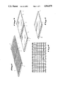
- FIG. 8 is still another exploded view of another preferred embodiment of a lead-acid battery according to the present invention.
- FIG. 14 is an isometric view showing one preferred method of adding acid to a battery according to the present invention.
- the second layer of plates 12, consisting of three biplates, is then laid upon the separators in such a fashion that each part of the biplate of this second layer is of opposite polarity to the end-plate or part of the biplate directly underneath it in the first layer.
- FIGS. 6 and 7 show other possible layouts of the stacks of plates using the concept described above. It is shown in FIG. 8 (using the layout of FIG. 5 as an example) the path of electrons during a discharge of a battery so constructed is from an external electrical circuit into the wires 10 of the positive end-plates 6; thence into the positive active material of the end-plate; vertically up and/or down through the electrolyte contained in the interleaved separator into the active material and grid of the adjacent negative plates; through the interstack connector wires in the unpasted portion of the biplate to the positive plate of the biplate; up and/or down through electrolyte contained in the interleaved separator into the active material and grid of the adjacent negative plate; through the interstack connector wires in the unpasted part of the biplate into the grid and active material part of the positive plate of the biplate and so on to the wires of the negative end-plate and out into the external electrical circuit.
- the battery should be put on formation immediately following the point at which the container side pieces were affixed to the container.
Abstract
Description
TABLE 1 __________________________________________________________________________ DESIGN AND PERFORMANCE CHARACTERISTICS OF BATTERIES OF THIS INVENTION. __________________________________________________________________________ SERIAL NO. 4J10E BATTERY VOLTAGE 4 4 NO. OF LAYERS OF BIPLATES 10 6 AREA OF EACH PLATE 3" × 3.25" 3" × 3.25" GRID ALLOY 99.98% Pb 99.98% Pb GRID DESIGN WOVEN MESH, 8 WEAVES PER 11 PARALLEL WIRES (FIG. 1) INCH (FIG. 2). .060" OUTSIDE DIA., .013" GLASS .050" OUTSIDE DIA., .013" GLASS FIBER CORE. FIBER CORE. WEIGHT OF BIPLATE GRID: 123 g. WEIGHT OF BIPLATE GRID: 32 g. POSITIVE ACTIVE MATERIAL NON-SULFATED PASTE, 73.34 g/in.sup.3 NON-SULFATED PASTE, 60.87 g/in.sup.3 WET DENSITY, 50 g WET PASTE WET DENSITY, 43 g WET PASTE WEIGHT PER PLATE. NO CURING/ WEIGHT PER PLATE. NO DRYING. CURING/DRYING. NEGATIVE ACTIVE MATERIAL NON-SULFATED PASTE, 76.9 g/in.sup.3 NON-SULFATED PASTE, 70.84 g/in.sup.3 WET DENSITY. 50 g WET PASTE WET DENSITY. 43 g WET PASTE WEIGHT PER PLATE. WEIGHT PER PLATE. NO CURING/DRYING NO CURING/DRYING SEPARATOR 2 PIECES EACH 3.25" × 3.25" × 1 PIECES EACH 3.25" × 3.25" × .050" THICK BEFORE .075" THICK BEFORE COMPRESSION. COMPRESSION. DEXTER TYPE EVANE TYPE AGM APPX .040" (EACH) APPX .060" (EACH) AFTER AFTER COMPRESSION. COMPRESSION. FILLING MATERIAL SEPARATORS PRE-SOAKED IN SEPARATORS ASSEMBLED DRY. 1.150 sg E.sub.2 SO.sub.4. BATTERY BATTERY SOAKED IN 1.350 sg SOAKED IN 1.300 sg H.sub.2 SO.sub.4 H.sub.2 SO.sub.4 FOR 1 HOUR AFTER 1 HOUR AFTER ASSEMBLY. ASSEMBLY.FORMATION 10 AMPS FOR 6 HOURS, 1.2 AMPS FOR 36HOURS 5 AMPS FOR 14.4 HOURS. FOLLOWED BY 0.3 AMPS FOR 12 HOURS. DISCHARGE NO. RECHARGE NO. 1 33.4 MINS @ 5.6 A TO 3.50 VOLTS 86 MINS @ 2.58 A TO 3.50 VOLTS 1 0.5 A FOR 28 HOURS 1.2 A FOR 4 HOURS, 0.2 A FOR 8 HOURS 2 35.4 MINS @ 5.6 A TO 3.50 VOLTS 101 MINS @ 2.61 A TO 3.50 VOLTS 2 CONSTANT POTENTIAL AT 2.50 vpc CONSTANT POTENTIAL AT 2.70 vpc 3 47.7 MINS @ 5.6 A TO 3.50 VOLTS 105 MINS @ 2.59 A TO 3.50 VOLTS 3 CONSTANT POTENTIAL AT 2.45 vpc CONSTANT POTENTIAL AT 2.70 vpc 4 115.6 MINS @ 5.6 A TO 3.50 VOLTS 106 MINS @ 2.63 A TO 3.50 VOLTS 4 CONSTANT POTENTIAL AT 2.45 vpc CONSTANT POTENTIAL AT 2.70 vpc 5 114.0 MINS @ 5.6 A TO 3.50 VOLTS 109 MINS @ 2.64 A TO 3.50 VOLTS 10 125 MINS @ 5.6 A TO 3.50 VOLTS 124 MINS @ 2.52 A TO 3.50 VOLTS 15 150.5 MINS @ 5.0 A TO 3.50 VOLTS 126 MINS @ 2.60 A TO 3.50 VOLTS 17 189.2 MINS @ 4.22 A TO 3.50 VOLTS 129 MINS @ 2.61 A TO 3.50 VOLTS 25 126 MINS @ 5.6 A TO 3.50 VOLTS 130 MINS @ 2.64 A TO 3.50 VOLTS 35 102 MINS @ 5.6 A TO 3.50 VOLTS 117 MINS @ 2.60 A TO 3.50 VOLTS BATTERY DISMANTLED AFTER BATTERY CYCLING PAST 37 CYCLES 41 CYCLES 11A 12D 4 4 6 6 3" × 3.25" 3" × 3.25" Pb/.60% Sn Pb/.1% Sb 11 PARALLEL WIRES (FIG. 1) 11 PARALLEL WIRES (FIG. 1) .050" OUTSIDE DIA., .013" GLASS .050" OUTSIDE DIA., .013" GLASS FIBER CORE WEIGHT OF FIBER CORE WEIGHT OF BIPLATE GRID: 32 g BIPLATE GRID: 32 g NON-SULFATED PASTE, 60.87 g/in.sup.3 NON-SULFATED PASTE, 60.87 g/in.sup.3 WET DENSITY, 43 g WET PASTE WET DENSITY, 43 g WET PASTE WEIGHT PER PLATE. NO CURING/ WEIGHT PER PLATE. NO CURING/ DRYING. DRYING. NON-SULFATED PASTE, 70.84 g/in.sup.3 NON-SULFATED PASTE, 70.84 g/in.sup.3 WET DENSITY. 43 g WET PASTE WET DENSITY. 43 g WET PASTE WEIGHT PER PLATE. NO WEIGHT PER PLATE. NO CURING/DRYING. CURING/DRYING. 1 PIECES EACH 3.25" × 3.25" × 1 PIECES EACH 3.25" × 3.25" × .075" THICK BEFORE .075" THICK BEFORE COMPRESSION. EVANE TYPE AGM COMPRESSION. EVANE TYPE AGM APPX .046" (EACH) AFTER APPX .060" (EACH) AFTER COMPRESSION. COMPRESSION. SEPARATORS ASSEMBLED DRY. SEPARATORS ASSEMBLED DRY. BATTERY SOAKED IN 1.350 sg BATTERY SOAKED IN 1.350 sg E.sub.2 SO.sub.4 FOR 1 HOUR AFTER H.sub.2 SO.sub.4 FOR 1 HOUR AFTER ASSEMBLY. ASSEMBLY. 1.2 AMPS FOR 36 HOURS FOLLOW- 1.2 AMPS FOR 36 HOURS FOLLOW- ED BY 0.3 AMPS FOR 12 HOURS. ED BY 0.3 AMPS FOR 12 HOURS. 88 MINS @ 2.56 A TO 3.50VOLTS 67 MINS @ 2.60 A TO 3.50 VOLTS 1.2 A FOR 4 HOURS, 0.2 A FOR 8 1.2 A FOR 4 HOURS, 0.2 A FOR 8 HOURS HOURS 100 MINS @ 2.60 A TO 3.50 VOLTS 92 MINS @ 2.60 A TO 3.50 VOLTS CONSTANT POTENTIAL AT 2.70 vpc CONSTANT POTENTIAL AT 2.90 vpc 104 MINS @ 2.57 A TO 3.50 VOLTS 102 MINS @ 2.60 A TO 3.50 VOLTS CONSTANT POTENTIAL AT 2.70 vpc CONSTANT POTENTIAL AT 2.90 vpc 108 MINS @ 2.57 A TO 3.50 VOLTS 108 MINS @ 2.61 A TO 3.50 VOLTS CONSTANT POTENTIAL AT 2.70 vpc CONSTANT POTENTIAL AT 2.90 vpc 113 MINS @ 2.54 A TO 3.50 VOLTS 113 MINS @ 2.60 A TO 3.50 VOLTS 121 MINS @ 2.60 A TO 3.50 VOLTS 124 MINS @ 2.61 A TO 3.50 VOLTS 128 MINS @ 2.60 A TO 3.50 VOLTS 114 MINS @ 2.62 A TO 3.50 VOLTS 128 MINS @ 2.63 A TO 3.50VOLTS 131 MINS @ 2.62 A TO 3.50 VOLTS 127 MINS @ 2.59 A TO 3.50 VOLTS BATTERY DISMANTLED AFTER 21 81 MINS @ 2.60 A TO 3.50 VOLTS CYCLES BATTERY CYCLING PAST 41 CYCLES __________________________________________________________________________
Claims (24)
Priority Applications (4)
| Application Number | Priority Date | Filing Date | Title |
|---|---|---|---|
| US07/200,977 US4964878A (en) | 1988-06-01 | 1988-06-01 | Lead-acid rechargeable storage battery |
| EP89906588A EP0419516A1 (en) | 1988-06-01 | 1989-05-22 | Lead-acid rechargeable storage battery |
| PCT/US1989/002242 WO1989012329A1 (en) | 1988-06-01 | 1989-05-22 | Lead-acid rechargeable storage battery |
| AU37417/89A AU3741789A (en) | 1988-06-01 | 1989-05-22 | Lead-acid rechargeable storage battery |
Applications Claiming Priority (1)
| Application Number | Priority Date | Filing Date | Title |
|---|---|---|---|
| US07/200,977 US4964878A (en) | 1988-06-01 | 1988-06-01 | Lead-acid rechargeable storage battery |
Publications (1)
| Publication Number | Publication Date |
|---|---|
| US4964878A true US4964878A (en) | 1990-10-23 |
Family
ID=22743966
Family Applications (1)
| Application Number | Title | Priority Date | Filing Date |
|---|---|---|---|
| US07/200,977 Expired - Lifetime US4964878A (en) | 1988-06-01 | 1988-06-01 | Lead-acid rechargeable storage battery |
Country Status (4)
| Country | Link |
|---|---|
| US (1) | US4964878A (en) |
| EP (1) | EP0419516A1 (en) |
| AU (1) | AU3741789A (en) |
| WO (1) | WO1989012329A1 (en) |
Cited By (36)
| Publication number | Priority date | Publication date | Assignee | Title |
|---|---|---|---|---|
| US5344466A (en) * | 1990-01-12 | 1994-09-06 | Sealed Energy Systems, Inc. | Method for the assembly of lead-acid batteries and associated apparatus |
| US5348817A (en) * | 1993-06-02 | 1994-09-20 | Gnb Battery Technologies Inc. | Bipolar lead-acid battery |
| US5409787A (en) * | 1993-02-17 | 1995-04-25 | Electrosource, Inc. | Battery plate compression cage assembly |
| US5429643A (en) * | 1993-06-02 | 1995-07-04 | Gnb Battery Technologies Inc. | Method of assembling a bipolar lead-acid battery and the resulting bipolar battery |
| US5441824A (en) * | 1994-12-23 | 1995-08-15 | Aerovironment, Inc. | Quasi-bipolar battery requiring no casing |
| US5993494A (en) * | 1997-07-25 | 1999-11-30 | Gnb Technologies, Inc. | Method of manufacturing modular components for a bipolar battery and the resulting bipolar battery |
| US6017653A (en) * | 1996-03-11 | 2000-01-25 | Gnb Technologies, Inc. | Method of manufacturing modular molded components for a bipolar battery and the resulting bipolar battery |
| US6641956B1 (en) * | 1999-08-05 | 2003-11-04 | Honda Giken Kogyo Kabushiki Kaisha | Electrode plate with a rounded corner and edge for storage battery |
| US20050208382A1 (en) * | 2004-03-19 | 2005-09-22 | Eaglepicher Horizon Batteries, Llc | Composite wire having impervious core for use in an energy storage device |
| US20060292443A1 (en) * | 2005-05-03 | 2006-12-28 | Randy Ogg | Bi-polar rechargeable electrochemical battery |
| US20080088276A1 (en) * | 2006-10-12 | 2008-04-17 | Aeron Hurst | Power supply modules having a uniform DC environment |
| US20080090139A1 (en) * | 2006-10-12 | 2008-04-17 | Aeron Hurst | Precision battery pack circuits |
| US20080118846A1 (en) * | 2006-11-17 | 2008-05-22 | Samsung Sdi Co., Ltd. | Rechargeable lithium battery |
| US20080220336A1 (en) * | 2007-03-08 | 2008-09-11 | Samsung Sdi Co., Ltd. | Electrolyte for rechargeable lithium battery and rechargeable lithium battery comprising same |
| US20090134718A1 (en) * | 2007-11-27 | 2009-05-28 | Xpower Solution, Llc | Portable Power Packs Having a Uniform DC Environment |
| US20090142655A1 (en) * | 2007-10-26 | 2009-06-04 | G4 Synergetics, Inc. | Dish shaped and pressure equalizing electrodes for electrochemical batteries |
| US20090181301A1 (en) * | 2007-12-14 | 2009-07-16 | Yong-Shik Kim | Lithium secondary battery |
| US20100203384A1 (en) * | 2009-01-27 | 2010-08-12 | G4 Synergetics, Inc. | Electrode folds for energy storage devices |
| US20100304191A1 (en) * | 2009-04-24 | 2010-12-02 | G4 Synergetics, Inc. | Energy storage devices having cells electrically coupled in series and in parallel |
| US20110050178A1 (en) * | 2009-09-03 | 2011-03-03 | Jin-Sung Kim | Electrolytic solution for lithium battery, lithium battery employing the same and method for operating the lithium battery |
| EP2157642A3 (en) * | 2008-07-29 | 2012-02-29 | ElringKlinger AG | Method for producing a bipolar cell and bipolar cell for a bipolar battery |
| US20140113177A1 (en) * | 2012-01-13 | 2014-04-24 | Energy Power Systems, LLC | Lead-acid battery design having versatile form factor |
| US8808914B2 (en) | 2012-01-13 | 2014-08-19 | Energy Power Systems, LLC | Lead-acid battery design having versatile form factor |
| CN104022315A (en) * | 2013-03-01 | 2014-09-03 | 常州优特科新能源科技有限公司 | Horizontal dual-polar pipe type colloid storage battery and preparation method thereof |
| US9263721B2 (en) | 2012-01-13 | 2016-02-16 | Energy Power Systems LLC | Lead-acid battery design having versatile form factor |
| US9595360B2 (en) | 2012-01-13 | 2017-03-14 | Energy Power Systems LLC | Metallic alloys having amorphous, nano-crystalline, or microcrystalline structure |
| CN107026287A (en) * | 2016-06-24 | 2017-08-08 | 巨江电源科技有限公司 | A kind of preparation method of plumbic acid horizon battery |
| CN108262223A (en) * | 2017-12-29 | 2018-07-10 | 广州倬粤动力新能源有限公司 | Pole plate coating methods |
| CN109888298A (en) * | 2019-03-14 | 2019-06-14 | 肇庆中特能科技投资有限公司 | A kind of S type battery based on bipolar plates |
| CN109888297A (en) * | 2019-03-14 | 2019-06-14 | 肇庆中特能科技投资有限公司 | A kind of battery stacked with bipolar plates and its manufactured battery |
| CN109921027A (en) * | 2019-03-14 | 2019-06-21 | 肇庆中特能科技投资有限公司 | A kind of bipolar plates |
| CN109935787A (en) * | 2019-03-14 | 2019-06-25 | 肇庆中特能科技投资有限公司 | A kind of bipolar plates and preparation method thereof |
| WO2021022954A1 (en) * | 2019-08-02 | 2021-02-11 | 山东牛千里电源科技有限公司 | Grid of lead-acid battery, and lead-acid battery |
| CN113078324A (en) * | 2020-01-03 | 2021-07-06 | 易德维新能源科技(宿迁)有限公司 | Method for manufacturing bipolar battery, bipolar plate and unipolar plate thereof |
| CN113113684A (en) * | 2021-03-30 | 2021-07-13 | 天能电池集团股份有限公司 | Lead storage battery treatment method for improving wet pressure and discharge performance of unit cell |
| USD943551S1 (en) * | 2019-05-23 | 2022-02-15 | Tymphany Acoustic Technology (Huizhou) Co., Ltd. | Diaphragm for loudspeaker |
Families Citing this family (2)
| Publication number | Priority date | Publication date | Assignee | Title |
|---|---|---|---|---|
| FR2682536A1 (en) * | 1991-10-14 | 1993-04-16 | Sorapec | BIPOLAR ELECTRODES FOR LEAD ACCUMULATOR. |
| IT1270458B (en) * | 1993-07-13 | 1997-05-05 | Accumulatori S R L Soc It | ELECTRIC ACCUMULATOR. |
Citations (8)
| Publication number | Priority date | Publication date | Assignee | Title |
|---|---|---|---|---|
| US3167456A (en) * | 1961-06-01 | 1965-01-26 | Gen Motors Corp | Battery |
| GB1430205A (en) * | 1972-09-25 | 1976-03-31 | Dunlop Austrialia Ltd | Battery construction |
| GB2070844A (en) * | 1980-02-22 | 1981-09-09 | Chloride Group Ltd | Electric storage batteries |
| US4331747A (en) * | 1979-07-20 | 1982-05-25 | Chloride Group Limited | Electric storage batteries |
| US4353969A (en) * | 1979-09-27 | 1982-10-12 | California Institute Of Technology | Quasi-bipolar battery construction and method of fabricating |
| US4504556A (en) * | 1982-10-29 | 1985-03-12 | Chloride Group Public Limited Company | Multicell electric storage batteries |
| US4507856A (en) * | 1982-10-29 | 1985-04-02 | Chloride Group Public Limited Company | Method of assembling multicell electric storage batteries |
| US4734977A (en) * | 1986-03-25 | 1988-04-05 | Neste Oy | Method and apparatus for manufacturing storage battery plate assemblies |
Family Cites Families (14)
| Publication number | Priority date | Publication date | Assignee | Title |
|---|---|---|---|---|
| FR1092426A (en) * | 1953-10-22 | 1955-04-21 | Comp Generale Electricite | bipolar electrodes for batteries or accumulators and their production method |
| GB1032852A (en) * | 1962-01-29 | 1966-06-15 | Electric Storage Battery Co | Improvements in or relating to sealed electric storage batteries |
| DE2415032A1 (en) * | 1973-04-03 | 1974-10-24 | Tudor Ab | Lead accumulator electrode grid conductor - consisting of aluminium core with outer lead sheath extrusion |
| CA1051512A (en) * | 1973-05-23 | 1979-03-27 | Royce E. Biddick | Bipolar electrode using electrically conductive plastic substrate containing vitreous carbon |
| DE2558815C2 (en) * | 1975-12-27 | 1981-09-24 | Accumulatorenwerk Hoppecke Carl Zoellner & Sohn, 5000 Köln | Armored plate for lead accumulators |
| GB2052839B (en) * | 1979-05-09 | 1983-06-29 | Chloride Group Ltd | Electric storage batteries |
| GB2085645B (en) * | 1980-10-08 | 1984-05-10 | Chloride Group Ltd | Electric storage batteries |
| US4539268A (en) * | 1981-07-02 | 1985-09-03 | California Institute Of Technology | Sealed bipolar multi-cell battery |
| US4603093A (en) * | 1983-02-03 | 1986-07-29 | California Institute Of Technology | Lead-acid battery |
| GB8325949D0 (en) * | 1983-09-28 | 1983-11-02 | Tungstone Batteries Ltd | Electric batteries |
| GB2158285A (en) * | 1984-05-01 | 1985-11-06 | Chloride Group Plc | Multicell electric storage batteries |
| US4658623A (en) * | 1984-08-22 | 1987-04-21 | Blanyer Richard J | Method and apparatus for coating a core material with metal |
| FI77543C (en) * | 1985-12-19 | 1989-03-10 | Neste Oy | ACKUMULATOR. |
| US4713304A (en) * | 1986-06-18 | 1987-12-15 | Gnb Incorporated | Method of preparing lead-acid battery plates and lead-acid batteries containing plates so prepared |
-
1988
- 1988-06-01 US US07/200,977 patent/US4964878A/en not_active Expired - Lifetime
-
1989
- 1989-05-22 EP EP89906588A patent/EP0419516A1/en not_active Withdrawn
- 1989-05-22 AU AU37417/89A patent/AU3741789A/en not_active Abandoned
- 1989-05-22 WO PCT/US1989/002242 patent/WO1989012329A1/en not_active Application Discontinuation
Patent Citations (9)
| Publication number | Priority date | Publication date | Assignee | Title |
|---|---|---|---|---|
| US3167456A (en) * | 1961-06-01 | 1965-01-26 | Gen Motors Corp | Battery |
| GB1430205A (en) * | 1972-09-25 | 1976-03-31 | Dunlop Austrialia Ltd | Battery construction |
| US4331747A (en) * | 1979-07-20 | 1982-05-25 | Chloride Group Limited | Electric storage batteries |
| US4353969A (en) * | 1979-09-27 | 1982-10-12 | California Institute Of Technology | Quasi-bipolar battery construction and method of fabricating |
| GB2070844A (en) * | 1980-02-22 | 1981-09-09 | Chloride Group Ltd | Electric storage batteries |
| US4504556A (en) * | 1982-10-29 | 1985-03-12 | Chloride Group Public Limited Company | Multicell electric storage batteries |
| US4507856A (en) * | 1982-10-29 | 1985-04-02 | Chloride Group Public Limited Company | Method of assembling multicell electric storage batteries |
| US4525438A (en) * | 1982-10-29 | 1985-06-25 | Chloride Group Public Limited Company | Recombination multicell electric storage battery |
| US4734977A (en) * | 1986-03-25 | 1988-04-05 | Neste Oy | Method and apparatus for manufacturing storage battery plate assemblies |
Cited By (51)
| Publication number | Priority date | Publication date | Assignee | Title |
|---|---|---|---|---|
| US5344466A (en) * | 1990-01-12 | 1994-09-06 | Sealed Energy Systems, Inc. | Method for the assembly of lead-acid batteries and associated apparatus |
| US5409787A (en) * | 1993-02-17 | 1995-04-25 | Electrosource, Inc. | Battery plate compression cage assembly |
| US5348817A (en) * | 1993-06-02 | 1994-09-20 | Gnb Battery Technologies Inc. | Bipolar lead-acid battery |
| US5429643A (en) * | 1993-06-02 | 1995-07-04 | Gnb Battery Technologies Inc. | Method of assembling a bipolar lead-acid battery and the resulting bipolar battery |
| US5470679A (en) * | 1993-06-02 | 1995-11-28 | Gnb Battery Technologies Inc. | Method of assembling a bipolar lead-acid battery and the resulting bipolar battery |
| US5441824A (en) * | 1994-12-23 | 1995-08-15 | Aerovironment, Inc. | Quasi-bipolar battery requiring no casing |
| US6017653A (en) * | 1996-03-11 | 2000-01-25 | Gnb Technologies, Inc. | Method of manufacturing modular molded components for a bipolar battery and the resulting bipolar battery |
| US5993494A (en) * | 1997-07-25 | 1999-11-30 | Gnb Technologies, Inc. | Method of manufacturing modular components for a bipolar battery and the resulting bipolar battery |
| US6641956B1 (en) * | 1999-08-05 | 2003-11-04 | Honda Giken Kogyo Kabushiki Kaisha | Electrode plate with a rounded corner and edge for storage battery |
| US20050208382A1 (en) * | 2004-03-19 | 2005-09-22 | Eaglepicher Horizon Batteries, Llc | Composite wire having impervious core for use in an energy storage device |
| US20060292443A1 (en) * | 2005-05-03 | 2006-12-28 | Randy Ogg | Bi-polar rechargeable electrochemical battery |
| US7794877B2 (en) | 2005-05-03 | 2010-09-14 | Randy Ogg | Bi-polar rechargeable electrochemical battery |
| US20100304216A1 (en) * | 2005-05-03 | 2010-12-02 | G4 Synergetics, Inc. | Bi-polar rechargeable electrochemical battery |
| US20080090139A1 (en) * | 2006-10-12 | 2008-04-17 | Aeron Hurst | Precision battery pack circuits |
| US7808131B2 (en) | 2006-10-12 | 2010-10-05 | Xtreme Power Inc. | Precision battery pack circuits |
| US8237407B2 (en) | 2006-10-12 | 2012-08-07 | Xtreme Power Inc. | Power supply modules having a uniform DC environment |
| US20080088276A1 (en) * | 2006-10-12 | 2008-04-17 | Aeron Hurst | Power supply modules having a uniform DC environment |
| US20080118846A1 (en) * | 2006-11-17 | 2008-05-22 | Samsung Sdi Co., Ltd. | Rechargeable lithium battery |
| US8802300B2 (en) * | 2006-11-17 | 2014-08-12 | Samsung Sdi Co., Ltd. | Rechargeable lithium battery |
| US20080220336A1 (en) * | 2007-03-08 | 2008-09-11 | Samsung Sdi Co., Ltd. | Electrolyte for rechargeable lithium battery and rechargeable lithium battery comprising same |
| US20090142655A1 (en) * | 2007-10-26 | 2009-06-04 | G4 Synergetics, Inc. | Dish shaped and pressure equalizing electrodes for electrochemical batteries |
| US8632901B2 (en) | 2007-10-26 | 2014-01-21 | G4 Synergetics, Inc. | Dish shaped and pressure equalizing electrodes for electrochemical batteries |
| US20090134718A1 (en) * | 2007-11-27 | 2009-05-28 | Xpower Solution, Llc | Portable Power Packs Having a Uniform DC Environment |
| US8198759B2 (en) | 2007-11-27 | 2012-06-12 | Xtreme Power Inc. | Portable power packs having a uniform DC environment |
| US20090181301A1 (en) * | 2007-12-14 | 2009-07-16 | Yong-Shik Kim | Lithium secondary battery |
| US8815454B2 (en) | 2007-12-14 | 2014-08-26 | Samsung Sdi Co., Ltd. | Lithium secondary battery |
| EP2157642A3 (en) * | 2008-07-29 | 2012-02-29 | ElringKlinger AG | Method for producing a bipolar cell and bipolar cell for a bipolar battery |
| US20100203384A1 (en) * | 2009-01-27 | 2010-08-12 | G4 Synergetics, Inc. | Electrode folds for energy storage devices |
| US8859132B2 (en) | 2009-01-27 | 2014-10-14 | G4 Synergetics, Inc. | Variable volume containment for energy storage devices |
| US20100304191A1 (en) * | 2009-04-24 | 2010-12-02 | G4 Synergetics, Inc. | Energy storage devices having cells electrically coupled in series and in parallel |
| US20110050178A1 (en) * | 2009-09-03 | 2011-03-03 | Jin-Sung Kim | Electrolytic solution for lithium battery, lithium battery employing the same and method for operating the lithium battery |
| US9093702B2 (en) | 2009-09-03 | 2015-07-28 | Samsung Sdi Co., Ltd. | Electrolytic solution for lithium battery, lithium battery employing the same and method for operating the lithium battery |
| US20140113177A1 (en) * | 2012-01-13 | 2014-04-24 | Energy Power Systems, LLC | Lead-acid battery design having versatile form factor |
| US8808914B2 (en) | 2012-01-13 | 2014-08-19 | Energy Power Systems, LLC | Lead-acid battery design having versatile form factor |
| US20150010807A1 (en) * | 2012-01-13 | 2015-01-08 | Energy Power Systems, LLC | Lead-acid battery design having versatile form factor |
| US9263721B2 (en) | 2012-01-13 | 2016-02-16 | Energy Power Systems LLC | Lead-acid battery design having versatile form factor |
| US9595360B2 (en) | 2012-01-13 | 2017-03-14 | Energy Power Systems LLC | Metallic alloys having amorphous, nano-crystalline, or microcrystalline structure |
| CN104022315A (en) * | 2013-03-01 | 2014-09-03 | 常州优特科新能源科技有限公司 | Horizontal dual-polar pipe type colloid storage battery and preparation method thereof |
| CN107026287B (en) * | 2016-06-24 | 2020-12-22 | 巨江电源科技有限公司 | Manufacturing method of lead-acid horizontal battery |
| CN107026287A (en) * | 2016-06-24 | 2017-08-08 | 巨江电源科技有限公司 | A kind of preparation method of plumbic acid horizon battery |
| CN108262223A (en) * | 2017-12-29 | 2018-07-10 | 广州倬粤动力新能源有限公司 | Pole plate coating methods |
| CN108262223B (en) * | 2017-12-29 | 2020-05-12 | 广州倬粤动力新能源有限公司 | Polar plate coating method |
| CN109888298A (en) * | 2019-03-14 | 2019-06-14 | 肇庆中特能科技投资有限公司 | A kind of S type battery based on bipolar plates |
| CN109888297A (en) * | 2019-03-14 | 2019-06-14 | 肇庆中特能科技投资有限公司 | A kind of battery stacked with bipolar plates and its manufactured battery |
| CN109921027A (en) * | 2019-03-14 | 2019-06-21 | 肇庆中特能科技投资有限公司 | A kind of bipolar plates |
| CN109935787A (en) * | 2019-03-14 | 2019-06-25 | 肇庆中特能科技投资有限公司 | A kind of bipolar plates and preparation method thereof |
| USD943551S1 (en) * | 2019-05-23 | 2022-02-15 | Tymphany Acoustic Technology (Huizhou) Co., Ltd. | Diaphragm for loudspeaker |
| WO2021022954A1 (en) * | 2019-08-02 | 2021-02-11 | 山东牛千里电源科技有限公司 | Grid of lead-acid battery, and lead-acid battery |
| CN113078324A (en) * | 2020-01-03 | 2021-07-06 | 易德维新能源科技(宿迁)有限公司 | Method for manufacturing bipolar battery, bipolar plate and unipolar plate thereof |
| CN113113684A (en) * | 2021-03-30 | 2021-07-13 | 天能电池集团股份有限公司 | Lead storage battery treatment method for improving wet pressure and discharge performance of unit cell |
| CN113113684B (en) * | 2021-03-30 | 2022-06-10 | 天能电池集团股份有限公司 | Lead storage battery treatment method for improving wet pressure and discharge performance of unit cell |
Also Published As
| Publication number | Publication date |
|---|---|
| EP0419516A1 (en) | 1991-04-03 |
| AU3741789A (en) | 1990-01-05 |
| WO1989012329A1 (en) | 1989-12-14 |
Similar Documents
| Publication | Publication Date | Title |
|---|---|---|
| US4964878A (en) | Lead-acid rechargeable storage battery | |
| US5348817A (en) | Bipolar lead-acid battery | |
| JP5079324B2 (en) | Lead acid battery | |
| US4603093A (en) | Lead-acid battery | |
| US5441824A (en) | Quasi-bipolar battery requiring no casing | |
| US9263721B2 (en) | Lead-acid battery design having versatile form factor | |
| US3819412A (en) | Plates for lead acid batteries | |
| EP0592548B1 (en) | Bipolar battery and method of making a partition wall for such a battery | |
| JP7369189B2 (en) | Agents useful in balancing power density and energy density in battery assemblies | |
| EP1717896B1 (en) | Lead acid battery | |
| US4037031A (en) | Bipolar lead acid battery having titanium and zirconium electrode supports | |
| US5993494A (en) | Method of manufacturing modular components for a bipolar battery and the resulting bipolar battery | |
| US4855196A (en) | Multilaminate material and separator assembly for electrochemical cells | |
| US2713079A (en) | Battery plate | |
| US8808914B2 (en) | Lead-acid battery design having versatile form factor | |
| Perkins | Materials and mechanisms determining the performance of lead-acid storage batteries an invited review | |
| US4572879A (en) | Lead-acid cell and method of producing same | |
| US4873161A (en) | Positive paste with lead-coated glass fibers | |
| EP2803097A1 (en) | Lead-acid battery design having versatile form factor | |
| US5001022A (en) | Lead-acid storage battery and related method of construction | |
| EP0051349B1 (en) | A lead - acid battery construction | |
| Valeriote et al. | Variables affecting the deep-cycling characteristics of expanded-grid lead/acid battery plates | |
| EP0475999B1 (en) | A method for electrochemically treating battery plate stock | |
| AU669464B2 (en) | Galvanic cells and batteries having a novel grid, strap and intercell weld arrangement | |
| HU196533B (en) | Lead accumulator, preferably for long-lasting uniform employment |
Legal Events
| Date | Code | Title | Description |
|---|---|---|---|
| AS | Assignment |
Owner name: ELECTROSOURCE INC., 38008 DROSSETT DRIVE, AUSTIN, Free format text: ASSIGNMENT OF ASSIGNORS INTEREST.;ASSIGNOR:MORRIS, CHRIS;REEL/FRAME:004885/0834 Effective date: 19880527 Owner name: ELECTROSOURCE INC., A CORP. OF DE.,TEXAS Free format text: ASSIGNMENT OF ASSIGNORS INTEREST;ASSIGNOR:MORRIS, CHRIS;REEL/FRAME:004885/0834 Effective date: 19880527 |
|
| FPAY | Fee payment |
Year of fee payment: 4 |
|
| FEPP | Fee payment procedure |
Free format text: PAT HOLDER CLAIMS SMALL ENTITY STATUS - SMALL BUSINESS (ORIGINAL EVENT CODE: SM02); ENTITY STATUS OF PATENT OWNER: SMALL ENTITY |
|
| FPAY | Fee payment |
Year of fee payment: 8 |
|
| FEPP | Fee payment procedure |
Free format text: PETITION RELATED TO MAINTENANCE FEES FILED (ORIGINAL EVENT CODE: PMFP); ENTITY STATUS OF PATENT OWNER: SMALL ENTITY |
|
| REMI | Maintenance fee reminder mailed | ||
| REIN | Reinstatement after maintenance fee payment confirmed | ||
| FEPP | Fee payment procedure |
Free format text: PETITION RELATED TO MAINTENANCE FEES FILED (ORIGINAL EVENT CODE: PMFP); ENTITY STATUS OF PATENT OWNER: SMALL ENTITY |
|
| FEPP | Fee payment procedure |
Free format text: PETITION RELATED TO MAINTENANCE FEES GRANTED (ORIGINAL EVENT CODE: PMFG); ENTITY STATUS OF PATENT OWNER: SMALL ENTITY |
|
| FP | Lapsed due to failure to pay maintenance fee |
Effective date: 20021023 |
|
| FPAY | Fee payment |
Year of fee payment: 12 |
|
| SULP | Surcharge for late payment | ||
| PRDP | Patent reinstated due to the acceptance of a late maintenance fee |
Effective date: 20030604 |
|
| STCF | Information on status: patent grant |
Free format text: PATENTED CASE |
|
| FEPP | Fee payment procedure |
Free format text: PAYOR NUMBER ASSIGNED (ORIGINAL EVENT CODE: ASPN); ENTITY STATUS OF PATENT OWNER: SMALL ENTITY |
|
| AS | Assignment |
Owner name: HORIZON BATTERIES, INC, TEXAS Free format text: REASSIGNMENT THROUGH BANKRUPTCY;ASSIGNOR:ELECTROSOURCE, INC.;REEL/FRAME:020442/0852 Effective date: 20030929 |