EP0652533B1 - Détection de l'état de fonctionnement d'une imprimante - Google Patents
Détection de l'état de fonctionnement d'une imprimante Download PDFInfo
- Publication number
- EP0652533B1 EP0652533B1 EP94117601A EP94117601A EP0652533B1 EP 0652533 B1 EP0652533 B1 EP 0652533B1 EP 94117601 A EP94117601 A EP 94117601A EP 94117601 A EP94117601 A EP 94117601A EP 0652533 B1 EP0652533 B1 EP 0652533B1
- Authority
- EP
- European Patent Office
- Prior art keywords
- cut
- printing apparatus
- data
- process execution
- error
- Prior art date
- Legal status (The legal status is an assumption and is not a legal conclusion. Google has not performed a legal analysis and makes no representation as to the accuracy of the status listed.)
- Expired - Lifetime
Links
Images


Classifications
-
- G—PHYSICS
- G06—COMPUTING; CALCULATING OR COUNTING
- G06K—GRAPHICAL DATA READING; PRESENTATION OF DATA; RECORD CARRIERS; HANDLING RECORD CARRIERS
- G06K15/00—Arrangements for producing a permanent visual presentation of the output data, e.g. computer output printers
-
- G—PHYSICS
- G06—COMPUTING; CALCULATING OR COUNTING
- G06F—ELECTRIC DIGITAL DATA PROCESSING
- G06F3/00—Input arrangements for transferring data to be processed into a form capable of being handled by the computer; Output arrangements for transferring data from processing unit to output unit, e.g. interface arrangements
- G06F3/12—Digital output to print unit, e.g. line printer, chain printer
- G06F3/1201—Dedicated interfaces to print systems
- G06F3/1202—Dedicated interfaces to print systems specifically adapted to achieve a particular effect
- G06F3/1203—Improving or facilitating administration, e.g. print management
- G06F3/1204—Improving or facilitating administration, e.g. print management resulting in reduced user or operator actions, e.g. presetting, automatic actions, using hardware token storing data
-
- G—PHYSICS
- G06—COMPUTING; CALCULATING OR COUNTING
- G06F—ELECTRIC DIGITAL DATA PROCESSING
- G06F3/00—Input arrangements for transferring data to be processed into a form capable of being handled by the computer; Output arrangements for transferring data from processing unit to output unit, e.g. interface arrangements
- G06F3/12—Digital output to print unit, e.g. line printer, chain printer
- G06F3/1201—Dedicated interfaces to print systems
- G06F3/1223—Dedicated interfaces to print systems specifically adapted to use a particular technique
- G06F3/1229—Printer resources management or printer maintenance, e.g. device status, power levels
-
- G—PHYSICS
- G06—COMPUTING; CALCULATING OR COUNTING
- G06F—ELECTRIC DIGITAL DATA PROCESSING
- G06F3/00—Input arrangements for transferring data to be processed into a form capable of being handled by the computer; Output arrangements for transferring data from processing unit to output unit, e.g. interface arrangements
- G06F3/12—Digital output to print unit, e.g. line printer, chain printer
- G06F3/1201—Dedicated interfaces to print systems
- G06F3/1278—Dedicated interfaces to print systems specifically adapted to adopt a particular infrastructure
- G06F3/1285—Remote printer device, e.g. being remote from client or server
-
- G—PHYSICS
- G06—COMPUTING; CALCULATING OR COUNTING
- G06K—GRAPHICAL DATA READING; PRESENTATION OF DATA; RECORD CARRIERS; HANDLING RECORD CARRIERS
- G06K15/00—Arrangements for producing a permanent visual presentation of the output data, e.g. computer output printers
- G06K15/02—Arrangements for producing a permanent visual presentation of the output data, e.g. computer output printers using printers
- G06K15/18—Conditioning data for presenting it to the physical printing elements
- G06K15/1801—Input data handling means
- G06K15/1803—Receiving particular commands
Definitions
- the present invention relates to a printing apparatus for printing according to commands received from a host computer, and relates particularly to a printing apparatus suitable for data processing apparatuses, such as point-of-sale (POS) terminals and electronic cash registers (ECR), used in processing monetary transactions.
- POS point-of-sale
- ECR electronic cash registers
- the printing apparatus even moves off-line when the form-feed switch is pressed and paper is being advanced, and when the data receive buffer storing the received data is full (a buffer full state), and it is difficult to distinguish between these off-line states and off-line states in which it is inappropriate to continue printing.
- the host computer When the printing apparatus goes off-line, the host computer is no longer able to send the print data, and the complete system, POS, ECR, or other, comes to a stop. In such a case, the host computer typically displays a message such as "printer problem, please check” on a display device, and the user must manually inspect the printing apparatus and correct the problem leading to the off-line state.
- determining the problem is often difficult and time-consuming.
- control commands stored in the data receive buffer are interpreted in a first-in-first-out (FIFO, the first commands stored are the first interpreted) order, and the appropriate command process is executed.
- Control commands that have been processed are deleted from the data receive buffer.
- the commands are stored one after the other to the data receive buffer, and processed in order from the oldest control command stored. This creates a time lag between output of the control command from the host computer and actual execution of the control command by the printing apparatus.
- the printer mechanism In conventional printing apparatuses handling cut-sheet forms, the printer mechanism must be stopped to wait for insertion of the cut-sheet form when the host computer selects a cut-sheet form for printing. Because internal control of the printing apparatus stops at this time, the data received from the host computer once the cut-sheet form selection has been made is not processed, and there is no response from the printing apparatus, until the cut-sheet form is inserted or a predetermined cut-sheet form insertion waiting period is completed.
- Errors generated in the printing apparatus include recoverable errors, such as paper jams in the paper transport path, and non-recoverable errors, such as problems with the power supply voltage from the AC-DC converter and damage to the head temperature detector of the printing head.
- the methods of handling recoverable and non-recoverable errors differ greatly, and it is therefore necessary to distinguish between the two; this is, however, difficult for the average user.
- the host computer in data processing systems using such conventional printing apparatuses adds a status request command to each line of data instead of batch sending plural lines of data, and uses the response to determine the current status of the printing apparatus. This, however, adds significant overhead to the host computer, and leads to reduced throughput in the data processing system.
- a printing apparatus according to the prior art portion of claims 1 and 4 and a method according to the prior art portion of claims 16 and 18 are disclosed in the document US-A-4,452,136.
- the document US-A-5,124,809 discloses a host system connected to an image forming device main frame comprising a controller and a print engine.
- the controller includes a data processing device receiving all data sent from the host system, and an image information processing device receiving and processing data that have already passed through the data processing device.
- the data processing device follows an input buffer and all data and commands received from the host system have to go through this input buffer.
- the object of the present invention is to provide a printing apparatus whereby the aforementioned problems of the prior art can be resolved; a high reliability data processing apparatus can be achieved; the overhead on the host computer can be reduced; and operation is user-friendly.
- the embodiment of claim 3 enables the host device to recover from errors in the printing apparatus.
- the host computer determines and evaluate the cause of an off-line printing apparatus state even after the printing apparatus goes off-line.
- the host computer can thus notify the user by means of posting a message, and the system can recover from the off-line state by means of host computer control if the user corrects the cause of the problem.
- the waiting state can be cancelled by the user issuing a 'cancel cut-sheet insertion waiting state command' from the host computer.
- the host computer when an error occurs in the printing apparatus, it is also possible for the host computer to determine what error occurred and where, and whether the error is recoverable or non-recoverable. When the error is recoverable, it is also possible to recover from the error and resume printing once the user corrects the cause of the error. It is also possible to select whether to resume printing from the print line at which the error occurred, or to destroy all data already sent and then recover from the error.
- recording paper used in the distribution industry is either cut-sheet or continuous forms paper.
- Cut-sheet paper includes irregularly sized, individual voucher forms called slip paper, and multiple-part individual voucher forms, called validation paper, of a relatively regular size.
- Continuous paper includes journal paper for printing and storing store records, and receipt paper used for simple receipts.
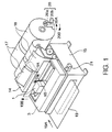
- Fig. 1 is an overview of a printing apparatus capable of printing to slip-, journal-, and receipt-type recording paper.
- this printing apparatus comprises print head 1, which is typically a so-called “wire dot head” comprising plural wire pins arrayed in a vertical line; and ink ribbon 3.
- the print head 1 prints while being driven in a reciprocal motion as indicated by arrows 1 A and 1B.
- Receipt paper 17 and journal paper 18 are inserted from the back of the printer mechanism in roll form, and are fed out from the top as shown in the figure.
- Slip paper 19 is inserted from the front of the printer mechanism (arrow 19A), and similarly fed out from the top (arrow 19B).
- Near-end detector 20 for detecting the end of the receipt and journal paper is also provided.
- Near-end detector 20 comprises a near-end detecting lever 20a, which is arranged to be pushed out in the direction of arrow 20A by the end face of the roll paper as long as the outside diameter of the end face is larger than a certain minimum value, and a push switch 20b, which is turned on/off by near-end detecting lever 20a.
- the outside diameter steadily decreases as the end of the roll paper approaches, and when the core of the roll paper is reached, near-end detecting lever 20a rotates in the direction of arrow 20B. This causes push switch 20b to switch OFF, thus detecting the near-end of the paper.
- receipt paper 17 is cut by cutter unit 14, and can be handed to the customer.
- the printer mechanism is covered by a housing not shown in the figures; this housing comprises a cover that is not shown and lower case 15.
- Cover detector 21 is an opposed-type photodetector, so called photo-interrupter. When the cover is closed, the beam from cover detector 21 is interrupted, and the cover is detected to be closed.
- Fig. 2 is a cross section illustrating the operation of the printing apparatus of the present invention during printing to continuous and cut-sheet paper.
- Fig. 2 (a) shows printing to continuous paper (receipt paper in the figure);
- wire pins (not shown in the figure) of print head 1 are provided in wire holder 1a for printing through ink ribbon 3 to receipt paper 17 against platen 2.
- Receipt paper 17 is fed by transport rollers 6a and 6b past guide roller 5 and between paper guides 4a and 4b.
- the one transport roller 6a is connected to a motor or other drive power source (not shown in the figures).
- Receipt paper detector 12 is a photo-interrupter, lever switch, or other detecting means positioned in the middle of paper guides 4a and 4b; receipt paper detector 12 is shown as a photo-interrupter in Fig. 2.
- receipt paper 17 passes between ink ribbon 3 and platen 2, through presser rollers 7a and 7b and cutter unit 14, and is fed out from the top of the printing apparatus.
- the cutter unit 14 comprises cutter blade 14a and cutter cover 14b; cutter blade 14a is driven in the direction of arrow 14A by a motor or other drive power source to cut receipt paper 17.
- journal paper is used for storing data by the store, and is not used for customer receipts.
- slip paper 19 is inserted from slip paper insertion opening 22 at the front of the printing apparatus in the direction of arrow 19A.
- slip transport roller 9a is pulled in the direction of arrow 10A by plunger 10 as shown in Fig. 2 (a), and is thus separated from the opposing slip transport roller 9b.
- slip paper 19 passes between slip paper guides 11a and 11b and abuts slip transport rollers 8a and 8b. Whether slip paper has been inserted is detected by slip paper detector 13. If paper has been inserted, plunger 10 is released and lever 10a moves in the direction of arrow 10B, thus pressing slip transport roller 9b against slip transport roller 9a, and holding slip paper 19 therebetween.
- Slip transport rollers 8b and 9b are connected to a motor or other drive power source not shown in the figures, and slip paper 19 is transported as slip transport rollers 8b and 9b and the opposing slip transport rollers 8a and 9a rotate in the direction of arrows 8A, 9B, and 8B, 9B respectively.
- slip paper 19 is fed out in the direction of arrow 19B, plunger 10 is driven to separate slip transport roller 9a from slip transport roller 9b, and the next slip paper form can be inserted.
- slip paper 19 Printing on slip paper 19 is possible with receipt paper 17 loaded as shown in the figure, and if carbon-copy paper is added to slip paper 19, the same information can be simultaneously printed to both slip paper 19 and receipt paper 17.
- slip paper detector 13 is a photo-interrupter similar to receipt paper detector 12.
- lower case 15 and case 16 supporting the head assembly are also shown.
- Fig. 3 is a schematic view illustrating a printing unit of the printing apparatus according to one embodiment of the invention.
- the printing unit comprises the print head 1 with wire holder 1a, a head carriage 1b and means for moving them.
- Print head 1 together with its wire holder 1 a, is fixed on head carriage 1b.
- Head carriage 1b is driven reciprocally side to side by carriage transfer belt 32 and carriage drive gears 31a and 31b; carriage drive gear 31a is connected to a head carriage drive motor not shown in the figure.
- This motor is normally a pulse motor, and is a pulse motor in this embodiment.
- Carriage drive gear 31a drives rotating detector plate 34 via transfer gear 33. Rotating detector plate 34 is positioned so as to interrupt the detection beam of carriage detector 35, which is also a photo-interrupter. Carriage detector 35 detects the rotation of rotating detector plate 34 caused by the movement of head carriage 1 b.
- rotating detector plate 34 is propeller-shaped, and when it rotates, the output of carriage detector 35 switches on/off on a regular period. More specifically, when head carriage 1b is driven reciprocally by the head carriage drive motor (not shown in the figure), the movement of head carriage 1b is detected by carriage detector 35.
- a "home position" for print head 1 is needed to determine a reference point for the print position.
- Home position detector 36 is also a photo-interrupter for detecting head carriage 1b. More specifically, when head carriage 1b moves to the left, the position at which the light beam from home position detector 36 is interrupted is the reference point for the home position.
- home position detector 36 can detect if print head 1 does not reach the home position due to a paper jam or other factor. A home position error occurs when head carriage 1b cannot be returned to the home position.
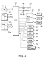
- FIG. 4 A circuit block diagram of a control circuit suitable for implementing the present invention is shown in Fig. 4.
- the mechanism of the printing apparatus of the invention as described above is represented as print head 40, motor group 41, and plunger group 42 in Fig. 4; this printer mechanism is driven by printer mechanism drive circuit 43.
- the printer mechanism also comprises carriage detector 44, home position detector 45, automatic cutter detector 46, paper detectors 47, and cover detectors 54, each of which is connected to central processing unit (CPU) 50.
- CPU central processing unit
- Automatic cutter detector 46 detects the position of cutter blade 14a (Fig. 2), drives the cutter blade drive motor (not shown in the figures), and generates the detector signal at a predetermined position. If a paper jam occurs in the cutter blades, the cutter blades will not move to the specified position, the detector signal will not be output, and an error is reported. This error is called a "cutter error.”
- Paper detectors 47 include near-end detector 20 (Fig. 1), receipt paper detector 12 and slip paper detector 13 (Fig. 2).
- CPU 50 which controls the entire printing apparatus
- display device 48 typically an LED unit
- panel switch (form feed switch) 49 for manually advancing the paper
- switch detector 75 for detecting a manual form feed caused by switch 49
- interface 51 for communications with the host computer
- ROM 52 for storing the control program, print character patterns, and other static information
- RAM 53 providing the receive buffer, print buffer, and other data buffers.
- peripheral device status detector 76 It serves to detect the status of a peripheral device that may be connected to the printing apparatus.
- An example of such peripheral device is the cash drawer of POS and ECR systems. In some embodiments of such systems the printing apparatus is designed to connect and drive the drawer in response to corresponding commands from the host computer.
- CPU 50 can drive display device 48 to notify the user that an error has occurred.
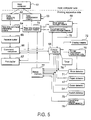
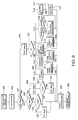
- Fig. 5 is a function block diagram showing the overall mechanism of the invention, and the relationships between the various functional means.
- Host computer 61 transmits the command data, print data, and other information to the printing apparatus.
- Data receiving means 62 receives the data codes from host computer 61 through interface 51, and is realized as a receive interrupt process activated through a receive interrupt by interface 51.
- Real-time command interpreting means 64 interprets and real-time process execution means 73 executes received real-time commands (explained later) immediately upon their receipt by the data receiving means.
- interpretation of the received data by means 64 comprises checking whether the received data is a real-time command and, if so, which type of real-time command.
- Real-time command interpreting means 64 and real-time process execution means 73 are realized as part of the same receive interrupt process as that of the data receiving means 62.
- the data receiving means 62, the real-time command interpreting means 64 and the real-time process execution means 73 are all formed by CPU 50 as are a command interpreter 66 and a control means 68 etc..
- Real-time command interpreting means 64 determines whether the received data is a real-time control command, and real-time process execution means 73 executes the specified process based on the command if the received data is determined to be a real-time control command.
- Real-time command interpreting means 64 and real-time process execution means 73 together will also be referred to as real-time command process means in the following.
- All received data passed through real-time command interpreting means 64 is stored temporarily to receive buffer 65.
- the received data buffered to receive buffer 65 is read one at a time by command interpreter 66, interpreted, and separated into print data and command data for controlling the printing apparatus.
- Command data is applied by control means 68 to execute the settings or operations corresponding to the command code.
- Print data is used to store the character patterns corresponding to the data codes to print buffer 67.
- control means 68 reads the character pattern from print buffer 67, and controls printer mechanism functional units 70 (mainly including print head 40, motor group 41, plunger group 42 and drive circuit 43) to print.
- the RS-232C two-way, serial interface is used as the interface in this embodiment because of its ability to maintain communications with the host computer even when the printing apparatus is off-line.
- the off-line status of a device can be detected by the host computer to which the device is connected, but because several bytes of data may have been loaded to the communication bus before data transmission can be stopped, it is necessary for the off-line device to receive this data even after it moves off-line. It is therefore necessary for the device to move off-line before the receive buffer becomes full, thereby enabling data to be received and stored to the receive buffer while capacity remains even when an error occurs and the printing apparatus goes off-line. Data received after the receive buffer becomes full, however, is thrown away.
- received commands are interpreted by real-time command interpreting means 64, which is activated by a receive interrupt, before being stored to the receive buffer.
- command can be processed even if the transmitted data is not stored.
- Real-time commands include commands requesting the status of the printing apparatus.
- real-time command process means 64, 73 responds by sending the current printing apparatus status to host computer 61 through data transmission means 63. It remains possible to send the printing apparatus status even when an error occurs because data receiving means 62, data transmission means 63, real-time command process means 64, 73 remain functional.
- control means 68 When the received command is determined by command interpreter 66 to be a cut-sheet form selection command, control means 68 is notified. Control means 68 thus notifies display means 72 that a cut-sheet form was selected, displays a prompt that the printing apparatus is waiting for cut-sheet form insertion, and stores cut-sheet forms information in RAM 53 by means of cut-sheet forms status storage means 79 to indicate that a cut-sheet form was selected and that the cut-sheet form insertion wait-state was entered. When a cut-sheet form is selected, paper detector 47 detects insertion of the cut-sheet form and notifies control means 68 when the form is inserted.
- Control means 68 monitors the cut-sheet form wait-state information, and stops printer mechanism drive until either the cut-sheet form wait-state information is deleted or cut-sheet form insertion is detected. By control means 68 stopping printer mechanism operation, command interpreter 66 also stops without being able to activate control means 68, but real-time command process means 64, 73 continues to operate irrespective of the cut-sheet form wait-state.
- Real-time commands include a command for cancelling the cut-sheet form wait-state.
- the cut-sheet form insertion wait-state information and cut-sheet form selection information stored to RAM 53 are deleted by real-time command process means 64, 73.
- control means 68 which monitors the cut-sheet form insertion wait-state, recognizes that the cut-sheet form insertion wait-state information has been deleted, it cancels the cut-sheet form insertion wait-state, clears print buffer 67, and selects the default paper type.
- the cut-sheet form insertion wait-state can be cancelled by a time-out, and control means 68 thus controls timer 78.
- control means 68 If a paper jam or other error occurs during printing, paper feeding, or paper cutting, an error is detected by error detector 71, control means 68 is notified, and the error information is stored to status memory 77. Control means 68 notifies display means 72 that an error has occurred, an error notice is displayed, and the error occurrence is stored as error information to RAM 53 by error status storage means 69.
- Control means 68 monitors the error information, and stops operation of the printer mechanism until the error information is cleared. By control means 68 stopping printer mechanism operation, command interpreter 66 also stops without being able to activate control means 68, but real-time command process means 64, 73, which is activated by a receive interrupt from interface 51, continues to operate irrespective of the error. Because command interpreter 66 is stopped and no longer reads the receive buffer, however, the data received by interface 51 is simply stored to receive buffer 65, and control means 68 therefore controls the interface to notify the host computer that the printing apparatus cannot accept anymore information (i.e., notifies the host computer that the printing apparatus is now off-line).
- the real-time commands also include a 'recover from error' command.
- real-time command process means 64, 73 deletes the error information stored to RAM 53.
- control means 68 which monitors this error status information, recognizes that the error information was deleted, it reactivates the printing apparatus to resume printing.
- Another 'recover from error' command is a command to resume printing after deleting all previously received data.
- receive buffer 65 and print buffer 67 are cleared by real-time command process means 64, 73, and the error information stored in RAM 53 is then deleted.
- the printing apparatus also goes off-line when a no-paper state is detected by paper detector 47, when an open-cover state is detected by cover detector 54, or when a manual form feed caused by the form feed switch (49 in Fig. 4) is detected by switch detector 75.
- These states are stored to status memory 77, and the information is reported to host computer 61 by real-time command process means 64, 73 via data transmission means 63.
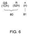
- Fig. 6 shows the command code for real-time commands in the present embodiment.
- received data [GS], [R], and [n] are each one byte long, expressed as 1D, 52, and n in hexadecimal code.
- [GS] and [R] indicate a real-time command 80; what is executed is selected according to the value of [n], i.e. the command's parameter 81.
- the printing apparatus status byte lone byte) shown in Table 2 is sent to the host computer.
- the drawer status, and printing apparatus on-line/off-line status can be determined by the host computer based on the printing apparatus status information.
- more specific off-line information can be obtained by setting [n] to 1.
- the off-line information byte (one byte) shown in Table 3 is sent to the host computer.
- the host computer can thus evaluate the off-line information, and can post prompts or other appropriate information to the user based on the evaluation result. If an error is determined to have occurred, detailed error information can be obtained by setting [n] to 2.
- the error information byte (one byte) shown in Table 4 is sent to the host computer.
- the mechanical errors shown in Table 4 refer primarily to errors due to a paper jam, but also include carriage errors and home position errors. These are further distinguished as paper jams around the print head and automatic paper cutter errors, thereby enabling the host computer to distinguish between paper jams occurring around the print head and in the automatic paper cutter. Based on this determination, the user is appropriately notified using the display means of the host computer where the error occurred, thus facilitating removal of the paper jam.
- Printing can be resumed when paper jam errors and similar errors occur by removing the paper jam or other error cause. Errors can also occur as a result of external power supply problems, damage to the print head temperature detector, and other causes making resumption of printing difficult, and it is necessary to distinguish these non-recoverable errors from recoverable errors (from which printing can be resumed). Errors other than paper jam errors are therefore identified as non-recoverable errors by setting bit 5.
- the slip paper detector information byte lone byte) shown in Table 6 is sent to the host computer. It is possible to determine from this slip status byte shown in Table 6 whether slip paper is selected or whether continuous or validation paper is selected. It is also possible to determine, when slip paper is selected, whether the printing apparatus is waiting for slip paper insertion, or whether the paper has already been loaded and printing can proceed.
- the validation paper detector information byte (one byte) shown in Table 7 is sent to the host computer. It is possible to determine from this validation paper status byte shown in Table 7 whether validation paper is selected or whether continuous or slip paper is selected. It is also possible to determine, when validation paper is selected, whether the printing apparatus is waiting for validation paper insertion, or whether the paper has already been loaded and printing can proceed.
- the data receiving means 62, the real-time command interpreting means 64 and the real-time process execution means 73 are described below with reference to Figs. 7 and 8.
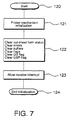
- Fig. 7 shows the printing apparatus initialization process, which starts immediately after the power is turned on (step 120).
- the printer mechanism is initialized (step 121), and all information in RAM 53 is initialized, including the cut-sheet form status flag, error information, clear-buffer flag, GS flag, and GSR flag (step 122).
- the clear-buffer flag, GS flag, and GSR flag are used in the receive interrupt process as will be explained in detail later.
- interface receive interrupts are enabled, and the initialization process is ended (step 124).
- Fig. 8 shows the receive interrupt process executed by the data receiving means 62, the real-time command interpreting means 64 and the real-time process execution means 73.
- the data received from the host computer through the interface is received one byte at a time, and the process shown in Fig. 8 is executed for every byte received.
- the real-time commands comprise three bytes, [GS], [R], and [n], as shown in Fig. 6, each real-time command is controlled by the GS flag, which is set when the [GS] byte is received; the GSR flag, which is set when the [R] byte is received and the GS flag is set; and the [n] byte received when the GSR flag is set.
- Step 125 Data is received and the receive interrupt is activated at step 125.
- step 126 the received data is read from the interface, and at step 127 it is determined whether the GSR flag is set. If the GSR flag is set, i.e., if the [GS] and [R] bytes have already been received, the received data ("C" in this example) is processed with the value of [n]. The GSR flag is cleared at step 136, and the following operation is executed based on the value of the received data (C) (step 137).
- the received data is also temporarily stored to the receive buffer even if the data is a real-time command (step 132).
- Fig. 9 Shown in Fig. 9 are the process from selection of cut-sheet form printing to loading the paper, and the process for cancelling the cut-sheet form print mode selection.
- step 151 This process starts (step 151) when command interpreter 66 determines that the input command is the cut-sheet form selection command, thus causing command interpreter 66 to set the cut-sheet form selection flag, and the cut-sheet form insertion wait flag (step 152). After confirming that mechanical operations are stopped (step 153), cut-sheet form insertion wait timer 78 is activated, and display device 48 is set flashing by display means 72 (step 155).
- step 156 it is determined whether the cut-sheet form insertion wait flag is cleared; if so, i.e., if the cut-sheet form insertion wait-state is cancelled by real-time command [GS] [R] [6], the cut-sheet form insertion wait timer 78 is stopped (step 157), and display device 48 is turned off by display means 72 (step 158).
- the cut-sheet form selection flag and cut-sheet form insertion wait flag are then cleared (step 159), the paper corresponding to the default paper type setting is set (step 160), and the cut-sheet form selection process is ended (step 161).
- step 162 If the cut-sheet form insertion wait flag is not cleared in step 156, it is determined if the cut-sheet form insertion wait period has passed (step 162); if the cut-sheet form insertion wait period has passed, the procedure skips forward to step 158.
- step 163 If the cut-sheet form insertion wait period has not passed in step 162, it is determined in step 163 whether the cut-sheet form is inserted. If the cut-sheet form is not inserted, the procedure loops back to step 156 to determine again whether the cut-sheet form insertion wait flag is cleared. The procedure then determines again whether the cut-sheet form insertion wait flag is cleared, whether the cut-sheet form insertion wait period has passed, and whether the cut-sheet form is inserted.
- step 163 If it is determined in step 163 that the cut-sheet form was inserted, the cut-sheet form insertion wait timer 78 is stopped (step 164), display device 48 is turned on (step 165), and the start-operation standby period is waited (step 166). If it is determined in step 167 that the cut-sheet form is not inserted, the procedure loops back to step 154, and the above operation is repeated.
- step 167 If it is determined in step 167 that the cut-sheet form is loaded, the cut-sheet form insertion wait flag is cleared (step 168), the cut-sheet form is set to the correct position (step 169), and the cut-sheet form selection process ends (step 161).
- a means of detecting carriage errors is described below as an embodiment of the invention for detecting errors with reference to Fig. 10.
- step 101 The process is started in step 101 by the print command, and the printing apparatus is initialized for one line in step 102.
- the line is then printed from steps 103 to 105.
- step 103 one dot row is printed and the head carriage is advanced one dot row.
- step 104 it is determined whether a detector pulse was output from carriage detector 35 due to carriage movement; the detector pulse is usually output on a regular cycle if the carriage advances normally.
- step 105 it is determined whether printing the one line is completed; if not, the procedure loops back to step 103. If the one row is completed, the procedure then ends at step 106.
- step 107 If the carriage is stopped at this time due to, for example, a paper jam, the detector pulse is not detected at step 104, and the procedure branches to step 107.
- the procedure from step 107 is the process executed when a carriage error occurs, and the first step (step 107) is to notify the host computer that the printing apparatus cannot receive further communication data, i.e., that it is off-line. That a carriage error has occurred is then stored to RAM 53 in step 108. Because a carriage error is a recoverable error, the error is stored as a recoverable error.
- the printer mechanism is also stopped in step 109.
- step 110 That an error occurred is then displayed (step 110) by the display device 48 until it is determined in step 111 that the error information has been deleted. If a corresponding real-time command is received, the error information is deleted, and it is determined in step 112 whether the received command indicates a clear buffer operation. If a clear buffer command has been received, the buffer is cleared in step 113; the buffers cleared at this time are both the receive buffer and print buffer.
- a printer mechanism reset operation is then executed in step 114, and the host computer is notified in step 115 that the printing apparatus can again receive data, i.e., is again on-line.
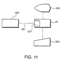
- Fig. 11 is a conceptual diagram of the data processing apparatus of the invention in which printing apparatus 300 is connected with host computer 61 by means of an RS-232C communication cable 301.
- Host computer 61 comprises an internal communication means 304 and an RS-232C interface control circuit.
- a CRT or other display device 302, and keyboard or other input device 303 are also connected to host computer 61.
- Fig. 12 is a flow chart of the control process of the host computer allowing cancellation of the cut-sheet form wait-state. Printing to slip paper is used as an example of cut-sheet form printing in Fig. 12.
- step 250 When slip paper printing is selected (step 250), the slip paper selection command is output (step 251). Real-time command [GS] [R] [4] is then sent to determine the slip paper status (step 252), and the corresponding response is received (step 253). This response contains the information shown in Table 6. Based on this information, the host computer determines whether slip paper has been selected (step 254).
- slip paper it is determined based on the information from step 253 whether the printing apparatus is waiting for slip paper insertion (step 255). If it is not waiting, it is first determined whether the slip paper is loaded (step 256); if so, the print data is output (step 257), and slip paper printing is completed (step 258).
- step 255 returns that the printing apparatus is waiting for slip paper insertion, the host computer monitors a specific key in input device 303, e.g., a "cancel slip paper” key, and determines whether this key is pressed (step 259).
- This key is specifically assigned the "cancel slip paper wait-state” function, and has to be operated by the user if he or she wants the slip paper selection cancelled.
- the "cancel slip paper wait-state" command [GS] [R] [6] will be output to cancel the slip paper wait-state (step 260).
- step 259 it is also possible to terminate slip paper printing (step 259) by monitoring this key when slip paper printing has been previously instructed but the command has not yet been executed, i. e., slip paper is not selected yet (step 254), or when there is no paper (step 256).
- sending the "cancel slip paper wait-state" command [GS] [R] [6] (step 260) will be ignored because the printing apparatus is not in the cut-sheet form insertion wait-state. If the key is not pressed, the process loops back to step 252, and the host computer waits for slip paper selection (step 254) or until the slip paper is loaded (step 256).
- Fig. 13 is a flow chart of the printing process in the host computer allowing for error recovery.
- the host computer After printing has started (step 200), the host computer checks whether the printing apparatus is still on-line (step 202) each time after one line of print data has been sent to the printing apparatus (step 201). In general, it is possible to determine with the RS-232C interface whether the receiving side (the printing apparatus in this case) is on-line from the CTS (Clear To Send) signal, the DSR (Data Set Ready) signal, or the XOFF code. If the printing apparatus is on-line, the host computer continues to send the print data. If there is no more print data (step 203), printing ends (step 204).
- step 202 If in step 202 the printing apparatus is off-line, it is possible that an error has occurred in the printing apparatus, or that printing has been disabled by some other factor (e.g., there is no more printing paper).
- the host computer sends real-time command [GS] [R] [2] in step 205.
- the response to this command is received in step 206, and used to determine (in step 207) whether an error occurred.
- the printing apparatus may be off-line for some reason other than an error; this reason is therefore investigated (step 208), and the appropriate action is taken (step 209).
- the host computer outputs real-time command [GS] [R] [1], and receives in response information that, for example, the cover is open or that there is no paper.
- the host computer can then display a user prompt such as "please close the cover” or "please add paper” on display device 302 to aid the user in correcting the problem.
- step 210 This sequence is repeated until the printing apparatus comes on-line again (step 210), at which point printing is resumed from step 201.
- step 207 determines that an error has occurred, it is determined whether the error is recoverable (step 211); this determination is based on the bit 5 value shown in Table 4. If the error is recoverable, the user is notified that an error has occurred, and can be requested to check the expected cause of the error, e.g., a paper jam. The location of the paper jam can also be reported to the user as being in the carriage or the automatic paper cutter based on the state of bits 2 and 3 in Table 4. After the user corrects the paper jam, the user confirms that the cause of the error has been corrected using input device 303 (e.g., a keyboard) of the host computer (step 213).
- input device 303 e.g., a keyboard
- Real-time command [GS] [R] [6] or [7] is then output to reset the printing apparatus from the error. Because it is possible that the user has not completely corrected the cause of the error, or that plural errors occurred simultaneously, the process after error recovery will preferably resume from step 205 to check again for errors.
- step 211 determines that the error is non-recoverable, there is a problem in the printing apparatus that may not be correctable by the user. In this case, the user is informed that there is a problem in the printing apparatus (step 215), and printing is stopped (step 216).
- a mode for recovering after deleting the already received data is also enabled, and this mode can be selected by a control command from the host computer. More specifically, in data processing apparatuses using printing apparatuses according to the prior art, the data already received is always destroyed after the printing apparatus recovers from the error. When the same data is printed after error recovery as before the error occurred, a special character is printed at the beginning of the line to indicate that the data in that line has been printed twice. A mode for error recovery after destroying the data already received is therefore necessary to maintain compatibility with this operation.
- the host computer can determine why the printing apparatus has gone off-line while the printing apparatus is off-line.
- commands can be interpreted and recovery from a cut-sheet form insertion wait-state is possible even during the cut-sheet form insertion wait-state.
- the host computer can determine whether the error is recoverable; if it is recoverable, the user can be notified where the error occurred, and printing can be resumed without destroying the data already received once the cause of the error is corrected.
Claims (25)
- Appareil d'impression ayant un mécanisme d'impression (40, 41, 42) pour imprimer sur un support d'impression et un moyen de commande (50) pour commander le mécanisme d'impression en réponse à des données reçues transmises en provenance d'un dispositif hôte (61), les données reçues comportant des ordres de commande et des données d'impression, ledit moyen de commande comprenant :caractérisé en ce queun moyen de réception (62) pour recevoir les données et les fournir en sortie en tant que premières données ;un moyen à tampon de réception (65) pour stocker au moins les ordres de commande parmi les premières données et les fournir en sortie en tant que secondes données dans un ordre premier entré-premier sorti ;un premier moyen d'interprétation d'ordre de commande (64) pour recevoir et interpréter les premières données ;un premier moyen d'exécution de traitement (73) pour exécuter le traitement correspondant à un ordre de commande interprété par le premier moyen d'interprétation d'ordre de commande (64) ;un second moyen d'interprétation d'ordre de commande (66) pour recevoir et interpréter les secondes données ;un second moyen d'exécution de traitement (68) pour exécuter le traitement correspondant à un ordre de commande interprété par le second moyen d'interprétation d'ordre de commande (66) ;un moyen de détection d'état du dispositif (47, 54, 69, 71, 75, 76, 77, 79) pour détecter un état de l'appareil d'impression (300) ;un moyen de transmission (63) pour transmettre des données au dispositif hôte (61) ; etun moyen de rapport d'état de dispositif pour rapporter des données obtenues par le moyen de détection d'état de dispositif au moyen de transmission ;un traitement correspondant à un ordre de commande interprété par le premier moyen d'interprétation d'ordre de commande est exécuté en priorité par rapport à un traitement correspondant à un ordre de commande interprété par le second moyen d'interprétation d'ordre de commande ;le moyen de détection d'état du dispositif comporte un moyen de détection d'état de fonctionnement destiné à détecter un état d'attente de l'appareil d'impression ;le moyen de commande comprend en outre un moyen de stockage d'indicateur d'état d'attente (53, 79) pour stocker un indicateur d'état d'attente en réponse à l'apparition d'un état d'attente, etle second moyen d'exécution de traitement (68) est apte à interrompre l'exécution d'un traitement pendant que l'indicateur d'état d'attente est mis ; et le premier moyen d'exécution de traitement (73) comprend un moyen de réinitialisation d'indicateur d'état d'attente pour réinitialiser l'indicateur d'état d'attente.
- Appareil d'impression suivant la revendication 1, dans lequel le moyen de détection d'état d'attente comprend un moyen de détection d'état d'erreur pour détecter un état d'erreur de l'appareil d'impression.
- Appareil d'impression suivant la revendication 2,dans lequel le moyen de commande comprend en outre un moyen de stockage d'indicateurs d'état d'erreur (69) pour stocker des indicateurs d'état d'erreur mis en réponse à l'apparition de l'état d'erreur détecté par le moyen de détection d'état d'erreur,dans lequel le second moyen d'exécution de traitement (68) est apte à interrompre l'exécution d'un traitement pendant que l'indicateur d'état d'erreur est positionné ; et le premier moyen d'exécution de traitement (73) comprend un moyen de réinitialisation d'indicateur d'état d'erreur pour réinitialiser l'indicateur d'état d'erreur.
- Appareil d'impression suivant la partie de la revendication 1 qui concerne l'art antérieur,
caractérisé en ce queun traitement correspondant à un ordre de commande interprété par le premier moyen d'interprétation d'ordre de commande est exécuté en priorité par rapport à un traitement correspondant à un ordre de commande interprété par le second moyen d'interprétation d'ordre de commande,le moyen de détection d'état du dispositif comporte un moyen de détection d'état d'erreur pour détecter un état d'erreur de l'appareil d'impression,le moyen de commande comprend un moyen de stockage d'indicateur d'état d'erreur (69) pour stocker un indicateur d'état d'erreur en réponse à l'apparition d'un état d'erreur, etle second moyen d'exécution de traitement (68) est apte à interrompre l'exécution d'un traitement pendant que l'indicateur d'état d'erreur est mis ; et le premier moyen d'exécution de traitement (73) comprend un moyen de réinitialisation d'indicateur d'état d'erreur pour réinitialiser l'indicateur d'état d'erreur. - Appareil d'impression suivant la revendication 2, 3 ou 4, dans lequel le moyen de détection d'état d'erreur comprend un moyen d'évaluation de récupération pour déterminer si oui ou non l'état d'erreur est récupérable.
- Appareil d'impression suivant l'une quelconque des revendications précédentes, comprenant en outre un élément de capot qui recouvre le mécanisme d'impression (40, 41, 42) lorsqu'il est fermé et expose le mécanisme d'impression lorsqu'il est ouvert, dans lequel le moyen de détection d'état du dispositif comprend un moyen de détection d'élément de capot (54) pour détecter l'état ouvert/fermé de l'élément de capot.
- Appareil d'impression suivant l'une quelconque des revendications précédentes, comprenant en outre un moyen de connexion de dispositif périphérique pour connecter un dispositif périphérique devant être commandé sur la base des ordres de commande, dans lequel le moyen de détection d'état du dispositif comprend un moyen de détection (76) destiné à détecter l'état du moyen de connexion de dispositif périphérique.
- Appareil d'impression suivant l'une quelconque des revendications précédentes, dans lequel le moyen de détection d'état du dispositif comprend un moyen de détection de support d'impression (47) pour détecter la présence et/ou la quantité restante de support d'impression disponible.
- Appareil d'impression suivant l'une quelconque des revendications précédentes, dans lequel le moyen de détection d'état du dispositif comprend un moyen de détection d'état de réglage pour détecter les réglages de l'appareil d'impression.
- Appareil d'impression suivant la revendication 9, comprenant en outre :un moyen de transport de feuille continue (6a, 6b) pour transporter et délivrer un support d'impression continu (17) à un moyen d'impression (1, 1a, 2) du mécanisme d'impression (40, 41, 42) ;un moyen de transport feuille à feuille (8a, 8b, 9a, 9b) pour transporter et délivrer des supports d'impression feuille à feuille (19) au moyen d'impression ; etun moyen de sélection de feuille à feuille pour interdire ou permettre le fonctionnement du moyen de transport de feuille à feuille ; etle moyen de détection d'état de réglage comprenant un moyen de détection de sélection de feuille à feuille (79) pour détecter l'état du moyen de sélection de feuille libre.
- Appareil d'impression suivant l'une quelconque des revendications précédentes, comprenant en outre :un moyen de transport feuille à feuille (8a, 8b, 9a, 9b) pour transporter et délivrer des supports d'impression feuille à feuille (17) à un moyen d'impression (1, 1a, 2) du mécanisme d'impression (40, 41, 42) ; etun moyen de commande de transport feuille à feuille (68) pour attendre qu'un support d'impression feuille à feuille soit délivré au moyen de transport feuille à feuille, puis pour commencer le transport du support d'impression à l'aide du moyen de transport feuille à feuille ;dans lequel le moyen de détection d'état de fonctionnement comprend un moyen de détection d'état de transport feuille à feuille (79) pour détecter l'état du moyen de commande de transport feuille à feuille.
- Appareil d'impression suivant l'une quelconque des revendications précédentes, dans lequel :le moyen de détection d'état du dispositif comprend un moyen de détection d'état de stockage de données pour détecter l'état du moyen à tampon de réception (65).
- Appareil d'impression suivant l'une quelconque des revendications précédentes, comprenant en outre :un moyen commutateur de transport de support d'impression (49) pour demander l'exécution de l'opération de transport de support d'impression indépendamment de l'ordre de commande ;dans lequel le moyen de détection d'état du dispositif comprend un moyen de détection de commutateur de transport (75) pour détecter l'état du commutateur de transport de support d'impression.
- Appareil d'impression suivant l'une quelconque des revendications précédentes, dans lequel :le premier moyen d'exécution de traitement (73) comprend en outre un moyen d'annulation de données reçues pour annuler les données reçues qui ont été stockées dans le moyen à tampon de réception (65).
- Appareil d'impression suivant la revendication 1 ou 4, comprenant en outre :un moyen de transport feuille à feuille (8a, 8b, 9a, 9b) pour transporter et délivrer des supports d'impression feuille à feuille (19) à un moyen d'impression (1, la, 2) du mécanisme d'impression (40, 41, 42) ;un moyen de commande de transport feuille à feuille (68) pour attendre qu'un support d'impression feuille à feuille soit délivré au moyen de transport feuille à feuille, puis pour commencer le transport du support d'impression à l'aide du moyen de transport feuille à feuille ; etun moyen de détection d'état de transport feuille à feuille (79) pour détecter l'état du moyen de commande de transport feuille à feuille ;dans lequel le premier moyen d'exécution de traitement (73) comprend un moyen d'annulation de l'état d'attente de la fourniture d'une feuille libre pour annuler le fonctionnement du moyen de commande de transport feuille à feuille lorsque l'état d'attente de fourniture d'une feuille libre du moyen de commande de transport feuille à feuille est détecté par le moyen de détection d'état de transport feuille à feuille.
- Procédé de commande d'un appareil d'impression en réponse à des données reçues transmises par un dispositif hôte pour une impression sur un support d'impression, les données reçues comportant des ordres de commande et des données d'impression ; le procédé de commande comprenant :caractérisé en ce queune étape de réception pour recevoir les données et les fournir en sortie en tant que premières données ;une étape de stockage pour stocker au moins des ordres de commande parmi les premières données et pour les fournir en sortie en tant que secondes données dans un ordre premier entré-premier sorti ;une première étape d'interprétation d'ordres de commande pour recevoir et interpréter les premières données ;une première étape d'exécution de traitement pour exécuter le traitement correspondant à un ordre de commande interprété lors de la première étape d'interprétation d'ordre de commande ;une seconde étape d'interprétation d'ordre de commande pour recevoir et interpréter les secondes données ;une seconde étape d'exécution de traitement pour exécuter le traitement correspondant à un ordre de commande interprété lors de la seconde étape d'interprétation d'ordre de commande ;une étape de détection d'état du dispositif pour détecter un état de l'appareil d'impression ; etune étape de transmission pour transmettre au dispositif hôte (61) des données obtenues lors de l'étape de détection d'état du dispositif ;la première étape d'exécution de traitement est exécutée en priorité par rapport à la seconde étape d'exécution de traitement, et l'étape de détection d'état du dispositif comporte une étape de détection d'état de fonctionnement pour détecter un état d'attente de l'appareil d'impression et une étape de stockage d'indicateur d'état d'attente pour stocker un indicateur d'état d'attente en réponse à l'apparition d'un état d'attente,dans lequel la seconde étape d'exécution de traitement interrompt l'exécution d'un traitement pendant que l'indicateur d'état d'attente est mis ; et la première étape d'exécution de traitement comprend une étape de réinitialisation d'indicateur d'état d'attente pour réinitialiser l'indicateur d'état d'attente.
- Procédé suivant la revendication 16, comprenant en outre :une étape de stockage d'indicateur d'état d'erreur pour mettre et stocker un indicateur d'état d'erreur lorsqu'un état d'erreur est détecté lors de l'étape de détection d'état de fonctionnement ;dans lequel la seconde étape d'exécution de traitement interrompt l'exécution d'un traitement pendant que l'indicateur d'état d'erreur est mis ; etla première étape d'exécution de traitement comprend une étape de réinitialisation d'indicateur d'état d'erreur pour réinitialiser l'indicateur d'état d'erreur.
- Procédé suivant la partie de la revendication 16 qui concerne l'art antérieur, caractérisé en ce que la première étape d'exécution de traitement est exécutée en priorité par rapport à la seconde étape d'exécution de traitement, eten ce que l'étape de détection d'état du dispositif comporte une étape de détection d'état de fonctionnement pour détecter un état d'erreur de l'appareil d'impression, et une étape de stockage d'indicateur d'état d'erreur pour stocker un indicateur d'état d'erreur en réponse à l'apparition d'un état d'erreur,dans lequel la seconde étape d'exécution de traitement interrompt l'exécution d'un traitement pendant que l'indicateur d'état d'erreur est mis, et la première étape d'exécution de traitement comprend une étape de réinitialisation d'indicateur d'état d'erreur pour réinitialiser l'indicateur d'état d'erreur.
- Procédé suivant la revendication 16, 17 ou 18, dans lequel la première étape d'exécution de traitement comprend en outre une étape d'annulation de données reçues pour annuler les données reçues stockées.
- Procédé suivant l'une quelconque des revendications 16 à 19, comprenant en outre :une étape de transport feuille à feuille pour attendre qu'un support d'impression feuille à feuille soit délivré et commencer le transport afin de délivrer le support d'impression feuille à feuille à un moyen d'impression du mécanisme d'impression (40, 41, 42) ;dans lequel la première étape d'exécution de traitement comprend une étape d'annulation d'état d'attente de fourniture de feuille libre pour annuler l'étape de transport feuille à feuille lorsque l'étape de transport feuille à feuille est dans l'état d'attente de transport feuille à feuille.
- Appareil de traitement de données, comprenant :un appareil d'impression suivant l'une quelconque des revendication 1 à 15 ; etun dispositif hôte (61) pour envoyer les données à l'appareil d'impression, lesquelles comprennent des ordres de commande et des données d'impression, dans lequel :le dispositif hôte comprend :un moyen de transmission d'ordre (304) pour transmettre à l'appareil d'impression (300) un ordre de rapport d'état du dispositif,ledit ordre étant un ordre de commande demandant la transmission des données de détection d'état du dispositif, et pouvant être interprété par le premier moyen d'interprétation d'ordre de commande.
- Appareil suivant la revendication 21, dans lequel le dispositif hôte (61) comprend en outre :un moyen d'affichage (61, 302) sensible aux données de détection d'état du dispositif reçues de l'appareil d'impression (300) en réponse à l'ordre d'affichage d'informations concernant l'état du dispositif.
- Appareil suivant la revendication 21 ou 22, dans lequel le dispositif hôte (61) comprend en outre un moyen de détermination pour déterminer si oui ou non un état d'erreur de l'appareil d'impression indiqué par les données de détection d'état de dispositif est récupérable et, si oui, le moyen de transmission d'ordre (304) transmet à l'appareil d'impression (300) un ordre de commande demandant à l'appareil d'impression de corriger l'état d'erreur, l'ordre de commande pouvant être interprété par le premier moyen d'interprétation d'ordre de commande (64).
- Appareil suivant la revendication 22 ou 23, dans lequel le moyen d'affichage (61, 302) affiche un message en conformité avec les données de détection d'état du dispositif envoyées par l'appareil d'impression (300) en réponse à cet ordre.
- Appareil suivant la revendication 24, dans lequel ledit message comporte une instruction que l'opérateur devra suivre pour améliorer l'état de l'appareil d'impression.
Applications Claiming Priority (9)
| Application Number | Priority Date | Filing Date | Title |
|---|---|---|---|
| JP27863793 | 1993-11-08 | ||
| JP27863793 | 1993-11-08 | ||
| JP27863893 | 1993-11-08 | ||
| JP27863893 | 1993-11-08 | ||
| JP27863993 | 1993-11-08 | ||
| JP278638/93 | 1993-11-08 | ||
| JP27863993 | 1993-11-08 | ||
| JP278639/93 | 1993-11-08 | ||
| JP278637/93 | 1993-11-08 |
Publications (3)
| Publication Number | Publication Date |
|---|---|
| EP0652533A2 EP0652533A2 (fr) | 1995-05-10 |
| EP0652533A3 EP0652533A3 (fr) | 1995-11-02 |
| EP0652533B1 true EP0652533B1 (fr) | 2002-02-13 |
Family
ID=27336570
Family Applications (1)
| Application Number | Title | Priority Date | Filing Date |
|---|---|---|---|
| EP94117601A Expired - Lifetime EP0652533B1 (fr) | 1993-11-08 | 1994-11-08 | Détection de l'état de fonctionnement d'une imprimante |
Country Status (5)
| Country | Link |
|---|---|
| US (1) | US5594653A (fr) |
| EP (1) | EP0652533B1 (fr) |
| DE (1) | DE69429849T2 (fr) |
| HK (1) | HK1014280A1 (fr) |
| SG (1) | SG66232A1 (fr) |
Cited By (1)
| Publication number | Priority date | Publication date | Assignee | Title |
|---|---|---|---|---|
| CN100340966C (zh) * | 1999-03-18 | 2007-10-03 | 精工爱普生株式会社 | 印刷装置、信息处理装置和它们的控制方法 |
Families Citing this family (73)
| Publication number | Priority date | Publication date | Assignee | Title |
|---|---|---|---|---|
| US6975423B2 (en) * | 1993-11-08 | 2005-12-13 | Seiko Epson Corporation | Printing apparatus and a control method therefor |
| US6362896B1 (en) | 1993-11-08 | 2002-03-26 | Seiko Epson Corporation | Printing apparatus with a cash drawer control function, and a control method therefor |
| CN100381941C (zh) * | 1995-02-22 | 2008-04-16 | 佳能株式会社 | 图象形成设备、图象形成系统以及向图象形成装置输出图象信息的设备 |
| US6000865A (en) * | 1995-08-22 | 1999-12-14 | Seiko Epson Corporation | Printing apparatus and a control method thereof |
| JP3250424B2 (ja) * | 1995-08-22 | 2002-01-28 | セイコーエプソン株式会社 | 印刷方式及び印刷方法 |
| EP0769737B1 (fr) * | 1995-10-13 | 2002-04-10 | Seiko Epson Corporation | Dispositif et méthode d'impression avec une fonction de commande des dispositifs externs |
| JPH09323463A (ja) * | 1996-06-05 | 1997-12-16 | Seiko Epson Corp | 通信端末およびその制御方法 |
| KR100212986B1 (ko) * | 1996-06-14 | 1999-08-02 | 윤종용 | 프린터의 이미지 화일 직접 인쇄방법 |
| JP3517527B2 (ja) * | 1996-08-23 | 2004-04-12 | キヤノン株式会社 | プリンタ制御装置及びプリンタの制御方法 |
| JP3689502B2 (ja) * | 1996-10-04 | 2005-08-31 | キヤノン株式会社 | 印刷制御装置および印刷制御方法 |
| JP3250718B2 (ja) * | 1996-10-22 | 2002-01-28 | セイコーエプソン株式会社 | プリントシステム |
| JPH10202986A (ja) * | 1997-01-28 | 1998-08-04 | Sharp Corp | 端末プリンタ装置 |
| JP3861958B2 (ja) * | 1998-03-26 | 2006-12-27 | セイコーエプソン株式会社 | オフラインからの復帰時の処理の種類を選択できる印刷装置、印刷方法、および、情報記録媒体 |
| JP3711433B2 (ja) * | 1998-05-06 | 2005-11-02 | セイコーエプソン株式会社 | 印刷制御方法及びシステム、記録媒体 |
| DE69904875T2 (de) | 1998-06-01 | 2003-08-28 | Seiko Epson Corp | Verfahren zur Überwachung des Stromversorgungszustands in einem an einen Hauptrechner angeschlossenen Peripheriegerät |
| EP0986001A3 (fr) * | 1998-09-08 | 2004-01-28 | International Business Machines Corporation | Méthode et appareil pour transmission d'information d'état et de commande d'une imprimante vers un système d'imprimante |
| KR100549978B1 (ko) | 1999-02-08 | 2006-02-08 | 세이코 엡슨 가부시키가이샤 | 인터페이스 장치, 그 제어 방법 및 정보 기록 매체 |
| JP4392902B2 (ja) * | 1999-06-02 | 2010-01-06 | キヤノン株式会社 | 印刷方法及び印刷方法をコンピュータに実行させるためのプログラムを記録する媒体 |
| JP4560917B2 (ja) * | 1999-10-15 | 2010-10-13 | セイコーエプソン株式会社 | プリンタ及びその制御方法 |
| US6886050B2 (en) | 1999-10-29 | 2005-04-26 | Seiko Epson Corporation | Method for controlling a communication terminal device and rewritable storage medium having initialization setting data |
| US6629796B2 (en) * | 2000-04-12 | 2003-10-07 | Seiko Epson Corporation | Printer |
| US6784906B2 (en) | 2001-12-18 | 2004-08-31 | Ncr Corporation | Direct thermal printer |
| US6759366B2 (en) | 2001-12-18 | 2004-07-06 | Ncr Corporation | Dual-sided imaging element |
| JP3961302B2 (ja) * | 2002-01-21 | 2007-08-22 | スター精密株式会社 | プリンタドライバおよびプリンタドライバのデータ処理方法 |
| JP3984876B2 (ja) * | 2002-07-03 | 2007-10-03 | キヤノン株式会社 | 画像形成装置および電力制御方法 |
| JP4296851B2 (ja) * | 2003-06-11 | 2009-07-15 | 富士ゼロックス株式会社 | 画像形成システム |
| JP2005007762A (ja) * | 2003-06-19 | 2005-01-13 | Seiko Epson Corp | 印刷装置、印刷システム、プログラムおよび端末装置の制御方法 |
| JP4251029B2 (ja) * | 2003-07-28 | 2009-04-08 | セイコーエプソン株式会社 | 印刷装置及びその制御方法 |
| JP2005254621A (ja) | 2004-03-11 | 2005-09-22 | Seiko Epson Corp | 電源制御装置及び電源制御方法 |
| EP2275918B1 (fr) | 2004-08-27 | 2014-04-16 | Seiko Epson Corporation | Imprimante et méthode de commande d'imprimante |
| JP2006062266A (ja) | 2004-08-27 | 2006-03-09 | Seiko Epson Corp | プリンタ及びプリンタの制御方法 |
| US7589752B2 (en) | 2005-01-15 | 2009-09-15 | Ncr Corporation | Two-sided thermal printing |
| KR100535442B1 (ko) * | 2005-04-18 | 2005-12-09 | 주식회사 빅솔론 | 프린팅 장치, 상기 프린팅 장치의 제어 방법 및 상기프린팅 장치를 이용한 데이터 처리 장치 |
| JP4682711B2 (ja) | 2005-06-08 | 2011-05-11 | セイコーエプソン株式会社 | 印刷装置、及び端末装置の制御方法 |
| US20060289633A1 (en) * | 2005-06-23 | 2006-12-28 | Ncr Corporation | Receipts having dual-sided thermal printing |
| US20070120943A1 (en) * | 2005-11-30 | 2007-05-31 | Ncr Corporation | Dual-sided thermal printing with labels |
| US20070120942A1 (en) * | 2005-11-30 | 2007-05-31 | Ncr Corporation | Dual-sided two color thermal printing |
| US8222184B2 (en) * | 2006-03-07 | 2012-07-17 | Ncr Corporation | UV and thermal guard |
| US8043993B2 (en) * | 2006-03-07 | 2011-10-25 | Ncr Corporation | Two-sided thermal wrap around label |
| US8721202B2 (en) * | 2005-12-08 | 2014-05-13 | Ncr Corporation | Two-sided thermal print switch |
| US8670009B2 (en) * | 2006-03-07 | 2014-03-11 | Ncr Corporation | Two-sided thermal print sensing |
| US7777770B2 (en) * | 2005-12-08 | 2010-08-17 | Ncr Corporation | Dual-sided two-ply direct thermal image element |
| US8067335B2 (en) * | 2006-03-07 | 2011-11-29 | Ncr Corporation | Multisided thermal media combinations |
| US7710442B2 (en) * | 2006-03-07 | 2010-05-04 | Ncr Corporation | Two-sided thermal print configurations |
| US20070134039A1 (en) * | 2005-12-08 | 2007-06-14 | Ncr Corporation | Dual-sided thermal printing |
| US20070213215A1 (en) * | 2006-03-07 | 2007-09-13 | Ncr Corporation | Multi-color dual-sided thermal printing |
| US8367580B2 (en) * | 2006-03-07 | 2013-02-05 | Ncr Corporation | Dual-sided thermal security features |
| US8462184B2 (en) | 2005-12-08 | 2013-06-11 | Ncr Corporation | Two-sided thermal printer control |
| US8083423B2 (en) * | 2006-03-01 | 2011-12-27 | Ncr Corporation | Thermal indicators |
| US8114812B2 (en) * | 2006-03-03 | 2012-02-14 | Ncr Corporation | Two-sided thermal paper |
| US7764299B2 (en) * | 2006-03-07 | 2010-07-27 | Ncr Corporation | Direct thermal and inkjet dual-sided printing |
| US8173575B2 (en) * | 2006-03-07 | 2012-05-08 | Ncr Corporation | Dual-sided thermal form card |
| US9024986B2 (en) * | 2006-03-07 | 2015-05-05 | Ncr Corporation | Dual-sided thermal pharmacy script printing |
| US7965404B2 (en) * | 2006-12-29 | 2011-06-21 | Pitney Bowes Inc. | Method for regenerating mailpiece content material in a mailpiece creation system |
| US8194107B2 (en) * | 2007-06-04 | 2012-06-05 | Ncr Corporation | Two-sided thermal print command |
| US8576436B2 (en) | 2007-06-20 | 2013-11-05 | Ncr Corporation | Two-sided print data splitting |
| US9056488B2 (en) * | 2007-07-12 | 2015-06-16 | Ncr Corporation | Two-side thermal printer |
| US8848010B2 (en) | 2007-07-12 | 2014-09-30 | Ncr Corporation | Selective direct thermal and thermal transfer printing |
| US7531224B2 (en) * | 2007-07-12 | 2009-05-12 | Ncr Corporation | Two-sided thermal transfer ribbon |
| US8211826B2 (en) | 2007-07-12 | 2012-07-03 | Ncr Corporation | Two-sided thermal media |
| US20090058892A1 (en) * | 2007-08-31 | 2009-03-05 | Ncr Corporation | Direct thermal and inkjet dual-sided printing |
| US8182161B2 (en) * | 2007-08-31 | 2012-05-22 | Ncr Corporation | Controlled fold document delivery |
| US8504427B2 (en) * | 2007-09-28 | 2013-08-06 | Ncr Corporation | Multi-lingual two-sided printing |
| JP2009131961A (ja) * | 2007-11-28 | 2009-06-18 | Brother Ind Ltd | 印刷装置 |
| US8279475B2 (en) | 2008-05-27 | 2012-10-02 | Bixolon Co., Ltd. | Printing apparatus and method for processing real-time command using the printing apparatus |
| KR100973021B1 (ko) * | 2008-07-09 | 2010-07-30 | 주식회사 빅솔론 | 우선 처리 식별자를 설정할 수 있는 프린터 장치 |
| US7839425B2 (en) | 2008-09-17 | 2010-11-23 | Ncr Corporation | Method of controlling thermal printing |
| JP5655453B2 (ja) | 2010-09-16 | 2015-01-21 | セイコーエプソン株式会社 | 電子機器、電子機器の制御方法、及び、プログラム |
| JP5691335B2 (ja) | 2010-09-17 | 2015-04-01 | セイコーエプソン株式会社 | 媒体処理装置、媒体処理装置の制御方法、及び、プログラム |
| JP5817193B2 (ja) | 2011-04-15 | 2015-11-18 | セイコーエプソン株式会社 | 記録装置、記録装置の制御方法、及び、プログラム |
| JP6593113B2 (ja) | 2015-11-09 | 2019-10-23 | セイコーエプソン株式会社 | プリンターの制御方法およびプリンター |
| JP7041390B2 (ja) * | 2018-02-20 | 2022-03-24 | セイコーエプソン株式会社 | 媒体搬送装置、画像読み取り装置、プログラム |
| CN109589548A (zh) * | 2018-11-09 | 2019-04-09 | 山东宝德龙医疗康复设备有限公司 | 一种综合康复训练系统 |
Family Cites Families (16)
| Publication number | Priority date | Publication date | Assignee | Title |
|---|---|---|---|---|
| US4452136A (en) * | 1979-10-19 | 1984-06-05 | International Business Machines Corporation | Printer subsystem with dual cooperating microprocessors |
| US4454575A (en) * | 1980-12-29 | 1984-06-12 | International Business Machines Corporation | Shared memory system with access by specialized peripherals managed by controller initialized by supervisory CPU |
| JPS619723A (ja) * | 1984-06-26 | 1986-01-17 | Mitsubishi Electric Corp | 印字出力エラ−回復方式 |
| JPS61175816A (ja) * | 1985-01-31 | 1986-08-07 | Toshiba Corp | 印字制御方式 |
| JPS61233578A (ja) * | 1985-04-10 | 1986-10-17 | Matsushita Electric Ind Co Ltd | プリンタ |
| US5088033A (en) * | 1986-04-28 | 1992-02-11 | Xerox Corporation | Data processing system emulation in a window with a coprocessor and I/O emulation |
| US4991972A (en) * | 1986-07-14 | 1991-02-12 | Minolta Camera Kabushiki Kaisha | Control apparatus for a printer |
| JPS6321178A (ja) * | 1986-07-14 | 1988-01-28 | Minolta Camera Co Ltd | プリンタ制御装置 |
| JPH071474B2 (ja) * | 1987-01-16 | 1995-01-11 | 東京電気株式会社 | プリンタ |
| JPS63276627A (ja) * | 1987-01-29 | 1988-11-14 | Hitachi Ltd | 印刷制御装置 |
| DE3811661A1 (de) * | 1987-04-07 | 1988-10-27 | Minolta Camera Kk | Druckeinrichtung |
| JPH01302453A (ja) * | 1988-05-31 | 1989-12-06 | Canon Inc | インターフェースシステム |
| JP2989191B2 (ja) * | 1988-11-16 | 1999-12-13 | 株式会社リコー | 画像形成システム |
| DE69117112T2 (de) * | 1990-08-08 | 1996-06-27 | Peerless Group | Verfahren und Vorrichtung zur Bildwiedergabe |
| US5428714A (en) * | 1990-11-16 | 1995-06-27 | Seiko Epson Corporation | Status and command function extension for industry standard printer interfaces |
| US5418891A (en) * | 1992-03-03 | 1995-05-23 | Yang; Jeng R. | Printer sharing device |
-
1994
- 1994-11-08 SG SG1996002221A patent/SG66232A1/en unknown
- 1994-11-08 DE DE69429849T patent/DE69429849T2/de not_active Expired - Lifetime
- 1994-11-08 US US08/335,604 patent/US5594653A/en not_active Expired - Lifetime
- 1994-11-08 EP EP94117601A patent/EP0652533B1/fr not_active Expired - Lifetime
-
1998
- 1998-12-24 HK HK98115557A patent/HK1014280A1/xx unknown
Cited By (1)
| Publication number | Priority date | Publication date | Assignee | Title |
|---|---|---|---|---|
| CN100340966C (zh) * | 1999-03-18 | 2007-10-03 | 精工爱普生株式会社 | 印刷装置、信息处理装置和它们的控制方法 |
Also Published As
| Publication number | Publication date |
|---|---|
| DE69429849D1 (de) | 2002-03-21 |
| SG66232A1 (en) | 1999-07-20 |
| US5594653A (en) | 1997-01-14 |
| DE69429849T2 (de) | 2002-08-22 |
| HK1014280A1 (en) | 1999-09-24 |
| EP0652533A2 (fr) | 1995-05-10 |
| EP0652533A3 (fr) | 1995-11-02 |
Similar Documents
| Publication | Publication Date | Title |
|---|---|---|
| EP0652533B1 (fr) | Détection de l'état de fonctionnement d'une imprimante | |
| US6434445B2 (en) | Printing apparatus with real-time cut-sheet waiting state cancellation | |
| US6457884B1 (en) | Printing apparatus and a control method therefor | |
| US6975423B2 (en) | Printing apparatus and a control method therefor | |
| US7869063B2 (en) | Printing apparatus, printer control method, printer control program, and printing system | |
| US7503712B2 (en) | Printing apparatus for selecting the appropriate error state mode according to the application type and user desired print results | |
| EP0834828B1 (fr) | Imprimante hybride équipée de plusieurs mécanismes d'impression, et sa méthode de contrôle | |
| US6122073A (en) | Communications terminal and interfacing method therefor | |
| US9473663B2 (en) | Control device, method of controlling a multifunction device, and a storage medium storing a program executed by a control unit that controls a recording device | |
| JP4924748B2 (ja) | プリンタ、及び受信データの処理方法 | |
| JP3552066B2 (ja) | 印刷装置及びその制御方法並びに該印刷装置を用いた情報処理装置 | |
| JP4623097B2 (ja) | 印刷装置 | |
| JP4088226B2 (ja) | 印刷装置 | |
| JP3544366B2 (ja) | 印刷装置及びその制御方法並びに該印刷装置を用いた情報処理装置 | |
| JP3544365B2 (ja) | 印刷装置及びその制御方法並びに該印刷装置を用いた情報処理装置 | |
| JP4865140B2 (ja) | プリンタ、受信データの処理方法及びプログラム | |
| JPH0313802Y2 (fr) | ||
| JPS6327287A (ja) | プリンタ | |
| JP3182879B2 (ja) | プリンタ及びその制御方法 |
Legal Events
| Date | Code | Title | Description |
|---|---|---|---|
| PUAI | Public reference made under article 153(3) epc to a published international application that has entered the european phase |
Free format text: ORIGINAL CODE: 0009012 |
|
| 17P | Request for examination filed |
Effective date: 19941108 |
|
| AK | Designated contracting states |
Kind code of ref document: A2 Designated state(s): CH DE FR GB IT LI NL SE |
|
| PUAL | Search report despatched |
Free format text: ORIGINAL CODE: 0009013 |
|
| AK | Designated contracting states |
Kind code of ref document: A3 Designated state(s): CH DE FR GB IT LI NL SE |
|
| 17Q | First examination report despatched |
Effective date: 19971209 |
|
| GRAG | Despatch of communication of intention to grant |
Free format text: ORIGINAL CODE: EPIDOS AGRA |
|
| GRAG | Despatch of communication of intention to grant |
Free format text: ORIGINAL CODE: EPIDOS AGRA |
|
| GRAH | Despatch of communication of intention to grant a patent |
Free format text: ORIGINAL CODE: EPIDOS IGRA |
|
| GRAH | Despatch of communication of intention to grant a patent |
Free format text: ORIGINAL CODE: EPIDOS IGRA |
|
| GRAA | (expected) grant |
Free format text: ORIGINAL CODE: 0009210 |
|
| REG | Reference to a national code |
Ref country code: GB Ref legal event code: IF02 |
|
| AK | Designated contracting states |
Kind code of ref document: B1 Designated state(s): CH DE FR GB IT LI NL SE |
|
| REG | Reference to a national code |
Ref country code: CH Ref legal event code: EP |
|
| REG | Reference to a national code |
Ref country code: CH Ref legal event code: NV Representative=s name: E. BLUM & CO. PATENTANWAELTE |
|
| REF | Corresponds to: |
Ref document number: 69429849 Country of ref document: DE Date of ref document: 20020321 |
|
| ET | Fr: translation filed | ||
| PLBE | No opposition filed within time limit |
Free format text: ORIGINAL CODE: 0009261 |
|
| STAA | Information on the status of an ep patent application or granted ep patent |
Free format text: STATUS: NO OPPOSITION FILED WITHIN TIME LIMIT |
|
| 26N | No opposition filed |
Effective date: 20021114 |
|
| REG | Reference to a national code |
Ref country code: CH Ref legal event code: PFA Owner name: SEIKO EPSON CORPORATION Free format text: SEIKO EPSON CORPORATION#4-1, NISHISHINJUKU 2-CHOME#SHINJUKU-KU, TOKYO 163-0811 (JP) -TRANSFER TO- SEIKO EPSON CORPORATION#4-1, NISHISHINJUKU 2-CHOME#SHINJUKU-KU, TOKYO 163-0811 (JP) |
|
| PGFP | Annual fee paid to national office [announced via postgrant information from national office to epo] |
Ref country code: CH Payment date: 20131112 Year of fee payment: 20 Ref country code: FR Payment date: 20131108 Year of fee payment: 20 Ref country code: GB Payment date: 20131106 Year of fee payment: 20 Ref country code: SE Payment date: 20131112 Year of fee payment: 20 Ref country code: DE Payment date: 20131106 Year of fee payment: 20 |
|
| PGFP | Annual fee paid to national office [announced via postgrant information from national office to epo] |
Ref country code: NL Payment date: 20131010 Year of fee payment: 20 Ref country code: IT Payment date: 20131119 Year of fee payment: 20 |
|
| REG | Reference to a national code |
Ref country code: DE Ref legal event code: R071 Ref document number: 69429849 Country of ref document: DE |
|
| REG | Reference to a national code |
Ref country code: CH Ref legal event code: PL |
|
| REG | Reference to a national code |
Ref country code: NL Ref legal event code: V4 Effective date: 20141108 |
|
| REG | Reference to a national code |
Ref country code: GB Ref legal event code: PE20 Expiry date: 20141107 |
|
| PG25 | Lapsed in a contracting state [announced via postgrant information from national office to epo] |
Ref country code: GB Free format text: LAPSE BECAUSE OF EXPIRATION OF PROTECTION Effective date: 20141107 |
|
| REG | Reference to a national code |
Ref country code: SE Ref legal event code: EUG |