EP0640503A1 - Elektrisches fahrzeug - Google Patents
Elektrisches fahrzeug Download PDFInfo
- Publication number
- EP0640503A1 EP0640503A1 EP94910051A EP94910051A EP0640503A1 EP 0640503 A1 EP0640503 A1 EP 0640503A1 EP 94910051 A EP94910051 A EP 94910051A EP 94910051 A EP94910051 A EP 94910051A EP 0640503 A1 EP0640503 A1 EP 0640503A1
- Authority
- EP
- European Patent Office
- Prior art keywords
- electric power
- regenerative
- storage battery
- air conditioner
- motor vehicle
- Prior art date
- Legal status (The legal status is an assumption and is not a legal conclusion. Google has not performed a legal analysis and makes no representation as to the accuracy of the status listed.)
- Granted
Links
Images


Classifications
-
- B—PERFORMING OPERATIONS; TRANSPORTING
- B60—VEHICLES IN GENERAL
- B60L—PROPULSION OF ELECTRICALLY-PROPELLED VEHICLES; SUPPLYING ELECTRIC POWER FOR AUXILIARY EQUIPMENT OF ELECTRICALLY-PROPELLED VEHICLES; ELECTRODYNAMIC BRAKE SYSTEMS FOR VEHICLES IN GENERAL; MAGNETIC SUSPENSION OR LEVITATION FOR VEHICLES; MONITORING OPERATING VARIABLES OF ELECTRICALLY-PROPELLED VEHICLES; ELECTRIC SAFETY DEVICES FOR ELECTRICALLY-PROPELLED VEHICLES
- B60L7/00—Electrodynamic brake systems for vehicles in general
- B60L7/22—Dynamic electric resistor braking, combined with dynamic electric regenerative braking
-
- B—PERFORMING OPERATIONS; TRANSPORTING
- B60—VEHICLES IN GENERAL
- B60H—ARRANGEMENTS OF HEATING, COOLING, VENTILATING OR OTHER AIR-TREATING DEVICES SPECIALLY ADAPTED FOR PASSENGER OR GOODS SPACES OF VEHICLES
- B60H1/00—Heating, cooling or ventilating [HVAC] devices
- B60H1/00357—Air-conditioning arrangements specially adapted for particular vehicles
- B60H1/00385—Air-conditioning arrangements specially adapted for particular vehicles for vehicles having an electrical drive, e.g. hybrid or fuel cell
- B60H1/00392—Air-conditioning arrangements specially adapted for particular vehicles for vehicles having an electrical drive, e.g. hybrid or fuel cell for electric vehicles having only electric drive means
-
- B—PERFORMING OPERATIONS; TRANSPORTING
- B60—VEHICLES IN GENERAL
- B60H—ARRANGEMENTS OF HEATING, COOLING, VENTILATING OR OTHER AIR-TREATING DEVICES SPECIALLY ADAPTED FOR PASSENGER OR GOODS SPACES OF VEHICLES
- B60H1/00—Heating, cooling or ventilating [HVAC] devices
- B60H1/00492—Heating, cooling or ventilating [HVAC] devices comprising regenerative heating or cooling means, e.g. heat accumulators
-
- B—PERFORMING OPERATIONS; TRANSPORTING
- B60—VEHICLES IN GENERAL
- B60H—ARRANGEMENTS OF HEATING, COOLING, VENTILATING OR OTHER AIR-TREATING DEVICES SPECIALLY ADAPTED FOR PASSENGER OR GOODS SPACES OF VEHICLES
- B60H1/00—Heating, cooling or ventilating [HVAC] devices
- B60H1/32—Cooling devices
- B60H1/3204—Cooling devices using compression
- B60H1/3205—Control means therefor
- B60H1/3208—Vehicle drive related control of the compressor drive means, e.g. for fuel saving purposes
-
- B—PERFORMING OPERATIONS; TRANSPORTING
- B60—VEHICLES IN GENERAL
- B60L—PROPULSION OF ELECTRICALLY-PROPELLED VEHICLES; SUPPLYING ELECTRIC POWER FOR AUXILIARY EQUIPMENT OF ELECTRICALLY-PROPELLED VEHICLES; ELECTRODYNAMIC BRAKE SYSTEMS FOR VEHICLES IN GENERAL; MAGNETIC SUSPENSION OR LEVITATION FOR VEHICLES; MONITORING OPERATING VARIABLES OF ELECTRICALLY-PROPELLED VEHICLES; ELECTRIC SAFETY DEVICES FOR ELECTRICALLY-PROPELLED VEHICLES
- B60L1/00—Supplying electric power to auxiliary equipment of vehicles
- B60L1/003—Supplying electric power to auxiliary equipment of vehicles to auxiliary motors, e.g. for pumps, compressors
-
- B—PERFORMING OPERATIONS; TRANSPORTING
- B60—VEHICLES IN GENERAL
- B60L—PROPULSION OF ELECTRICALLY-PROPELLED VEHICLES; SUPPLYING ELECTRIC POWER FOR AUXILIARY EQUIPMENT OF ELECTRICALLY-PROPELLED VEHICLES; ELECTRODYNAMIC BRAKE SYSTEMS FOR VEHICLES IN GENERAL; MAGNETIC SUSPENSION OR LEVITATION FOR VEHICLES; MONITORING OPERATING VARIABLES OF ELECTRICALLY-PROPELLED VEHICLES; ELECTRIC SAFETY DEVICES FOR ELECTRICALLY-PROPELLED VEHICLES
- B60L1/00—Supplying electric power to auxiliary equipment of vehicles
- B60L1/02—Supplying electric power to auxiliary equipment of vehicles to electric heating circuits
-
- B—PERFORMING OPERATIONS; TRANSPORTING
- B60—VEHICLES IN GENERAL
- B60L—PROPULSION OF ELECTRICALLY-PROPELLED VEHICLES; SUPPLYING ELECTRIC POWER FOR AUXILIARY EQUIPMENT OF ELECTRICALLY-PROPELLED VEHICLES; ELECTRODYNAMIC BRAKE SYSTEMS FOR VEHICLES IN GENERAL; MAGNETIC SUSPENSION OR LEVITATION FOR VEHICLES; MONITORING OPERATING VARIABLES OF ELECTRICALLY-PROPELLED VEHICLES; ELECTRIC SAFETY DEVICES FOR ELECTRICALLY-PROPELLED VEHICLES
- B60L50/00—Electric propulsion with power supplied within the vehicle
- B60L50/50—Electric propulsion with power supplied within the vehicle using propulsion power supplied by batteries or fuel cells
- B60L50/51—Electric propulsion with power supplied within the vehicle using propulsion power supplied by batteries or fuel cells characterised by AC-motors
-
- B—PERFORMING OPERATIONS; TRANSPORTING
- B60—VEHICLES IN GENERAL
- B60L—PROPULSION OF ELECTRICALLY-PROPELLED VEHICLES; SUPPLYING ELECTRIC POWER FOR AUXILIARY EQUIPMENT OF ELECTRICALLY-PROPELLED VEHICLES; ELECTRODYNAMIC BRAKE SYSTEMS FOR VEHICLES IN GENERAL; MAGNETIC SUSPENSION OR LEVITATION FOR VEHICLES; MONITORING OPERATING VARIABLES OF ELECTRICALLY-PROPELLED VEHICLES; ELECTRIC SAFETY DEVICES FOR ELECTRICALLY-PROPELLED VEHICLES
- B60L7/00—Electrodynamic brake systems for vehicles in general
- B60L7/10—Dynamic electric regenerative braking
- B60L7/14—Dynamic electric regenerative braking for vehicles propelled by ac motors
-
- B—PERFORMING OPERATIONS; TRANSPORTING
- B60—VEHICLES IN GENERAL
- B60T—VEHICLE BRAKE CONTROL SYSTEMS OR PARTS THEREOF; BRAKE CONTROL SYSTEMS OR PARTS THEREOF, IN GENERAL; ARRANGEMENT OF BRAKING ELEMENTS ON VEHICLES IN GENERAL; PORTABLE DEVICES FOR PREVENTING UNWANTED MOVEMENT OF VEHICLES; VEHICLE MODIFICATIONS TO FACILITATE COOLING OF BRAKES
- B60T1/00—Arrangements of braking elements, i.e. of those parts where braking effect occurs specially for vehicles
- B60T1/02—Arrangements of braking elements, i.e. of those parts where braking effect occurs specially for vehicles acting by retarding wheels
- B60T1/10—Arrangements of braking elements, i.e. of those parts where braking effect occurs specially for vehicles acting by retarding wheels by utilising wheel movement for accumulating energy, e.g. driving air compressors
-
- F—MECHANICAL ENGINEERING; LIGHTING; HEATING; WEAPONS; BLASTING
- F16—ENGINEERING ELEMENTS AND UNITS; GENERAL MEASURES FOR PRODUCING AND MAINTAINING EFFECTIVE FUNCTIONING OF MACHINES OR INSTALLATIONS; THERMAL INSULATION IN GENERAL
- F16D—COUPLINGS FOR TRANSMITTING ROTATION; CLUTCHES; BRAKES
- F16D61/00—Brakes with means for making the energy absorbed available for use
-
- F—MECHANICAL ENGINEERING; LIGHTING; HEATING; WEAPONS; BLASTING
- F01—MACHINES OR ENGINES IN GENERAL; ENGINE PLANTS IN GENERAL; STEAM ENGINES
- F01P—COOLING OF MACHINES OR ENGINES IN GENERAL; COOLING OF INTERNAL-COMBUSTION ENGINES
- F01P11/00—Component parts, details, or accessories not provided for in, or of interest apart from, groups F01P1/00 - F01P9/00
- F01P11/14—Indicating devices; Other safety devices
- F01P2011/205—Indicating devices; Other safety devices using heat-accumulators
-
- Y—GENERAL TAGGING OF NEW TECHNOLOGICAL DEVELOPMENTS; GENERAL TAGGING OF CROSS-SECTIONAL TECHNOLOGIES SPANNING OVER SEVERAL SECTIONS OF THE IPC; TECHNICAL SUBJECTS COVERED BY FORMER USPC CROSS-REFERENCE ART COLLECTIONS [XRACs] AND DIGESTS
- Y02—TECHNOLOGIES OR APPLICATIONS FOR MITIGATION OR ADAPTATION AGAINST CLIMATE CHANGE
- Y02T—CLIMATE CHANGE MITIGATION TECHNOLOGIES RELATED TO TRANSPORTATION
- Y02T10/00—Road transport of goods or passengers
- Y02T10/60—Other road transportation technologies with climate change mitigation effect
- Y02T10/70—Energy storage systems for electromobility, e.g. batteries
Definitions
- This invention relates to an electric motor vehicle which is provided with an electric air conditioner, and particularly to an electric motor vehicle which has an improved utilization efficiency of energy for the overall electric motor vehicle.
- this drive source for the electric motor vehicles is a motor which has a high efficiency but produces less heat. Therefore, its heat cannot be used for an air conditioning system unlike enormous waste heat which is produced by the operation of conventional internal combustion engines.
- a heat pump method is generally adopted for the air conditioner of the electric motor vehicle.
- a low- or high-temperature refrigerant which is used to heat or cool the cabin is evaporated or condensed by conducting a heat exchange with the open air by means of an exterior heat exchanger and returned to a compressor, thus being circulated within the system in the same way as a room air conditioner.
- a regenerative brake which uses the drive motor as a generator is generally used in place of the engine brake of a conventional internal combustion engine.
- kinetic energy which must be reduced when the electric motor vehicle decelerates or goes down a slope, is partly converted into electrical energy by temporarily using the drive motor as the generator, and this electrical energy is recovered into a storage battery, thus the drive motor provides a role of an auxiliary brake.
- a lead storage battery is generally used broadly in view of its cost and good resource balance.
- the lead storage battery has disadvantages that its performance is deteriorated and the service life is heavily ruined when the battery, which still has a remaining capacity higher than a prescribed level, is quickly recharged exceeding an appropriate charging current for the battery by high regenerative electric power.
- a conventional regenerative brake the gene rated regenerative electric power is lowered to protect the lead storage battery, and a common foot brake is used to supplement an insufficient braking force of the electric motor vehicle.
- Other known methods include a method in that excess regenerative electric power which cannot be recovered into the storage battery is lead to a resistor located outside of the cabin to generate heat so as to release the generated heat into the open air, thereby consuming the excess regenerative electric power, and a method in that a flywheel is rotated by the motor which uses the regenerative electric power, thereby saving as mechanical energy in the flywheel.
- a conventional electric motor vehicle uses as an energy source a storage battery whose energy capacity is very small as compared with a fuel such as gasoline and, therefore, has disadvantages that a ratio of energy consumed by the air conditioner to the above capacity is high, and when the air conditioner is operated, a mileage per charge is shortened extremely.
- the air conditioner of the electric motor vehicle operates to heat the cabin
- a cabin heat exchanger having a smaller heat exchanging capacity than a room air conditioner to sufficiently heat the cabin by introducing cold fresh air into the heat exchanger
- the compressor has an increased compression load and an increased rotating speed, so that the air conditioner consumes electric power heavily.
- a very low evaporating pressure value is set so that an evaporating temperature of the refrigerant becomes ten-odd °C lower than an outside-air temperature, e.g. -10 to -15°C, and a heating degree of 5 to 10°C is given for complete evaporation.
- an outside-air temperature e.g. -10 to -15°C
- a heating degree of 5 to 10°C is given for complete evaporation.
- the flow of the refrigerant is reduced.
- the performance factor of a refrigerating cycle is lowered, and the overall efficiency of the air conditioner is lowered.
- this air conditioner when this air conditioner is operated for cooling sufficiently by the cabin heat exchanger having a small heat exchanging capacity while introducing outside air of 30°C or more, it is necessary to make a difference between the refrigerant evaporating temperature and the outside-air temperature large as much as possible. For example, to provide the evaporating temperature of -10 to - 15 °C, a very low evaporating pressure value is set. As a result, there are disadvantages that a volumetric efficiency is lowered as the compression ratio of the compressor increases, a flow rate of the refrigerant is decreased as a specific volume of the low-pressure refrigerant increases, and a refrigerating capacity at a prescribed compressor speed is lowered, thus the performance factor of the air conditioner is lowered significantly.
- the electric motor vehicle needs to operate the air conditioner to heat.
- a low-temperature environment such as in winter when heating is required, an electrochemical change in the storage battery is inactive, and a charging and discharging capacity of the storage battery is lowered greatly.
- a heating load in the cabin increases, with the trend increasing the power consumption by the air conditioner.
- the performance of the storage battery is lowered and the air conditioner consumes huge electric power, so that a mileage per charge is heavily shortened than in any other seasons.
- this invention is to provide an electric motor vehicle whose actual mileage can be extended by effectively using excess regenerative electric power to improve an energy utilization efficiency of the overall electric motor vehicle.
- a first invention relates to an electric motor vehicle which is provided with a drive motor to be driven by electric power from a storage battery, an air conditioner, and a regenerative brake means which temporarily uses the motor as a generator when decelerating the vehicle to generate regenerative electric power and to charge the storage battery, and is characterized by an excess regenerative electric power judging means for judging excess regenerative electrical energy based on regenerative electrical energy by the regenerative brake and allowable regenerative electrical energy of the storage battery when the regenerative brake is operating, and an electric power distribution means for distributing the excess regenerative electric power to the air conditioner based on the excess regenerative electrical energy.
- a second invention relates to an electric motor vehicle which is provided with a drive motor to be driven by electric power from a storage battery, an air conditioner, and a regenerative brake means which temporarily uses the motor as a generator when decelerating the vehicle to generate regenerative electric power and to charge the storage battery, and is characterized by an excess regenerative electric power judging means for judging excess regenerative electrical energy based on regenerative electrical energy by the regenerative brake and allowable regenerative electrical energy of the storage battery when the regenerative brake is operating, and an electric power distribution means for distributing the excess regenerative electric power to a heat recovery circuit based on the excess regenerative electrical energy.
- Fig. 1 shows the entire block diagram of an air conditioner for the electric motor vehicle of this embodiment using a heat pump as a working principle of the air conditioner.
- Fig. 2 shows a control system chart of the air conditioner of this embodiment.
- the motive power of the air conditioner of this embodiment is the same as that of a compressor for the heat pump.
- an air conditioner 1 of this embodiment consists in the following order of a compressor 2 connected by piping, an oil separator 3, a four-way valve 4, an exterior heat exchanger 5, two pairs of expansion valves 6, 7, an interior heat exchanger 8, and an accumulator 9.
- a refrigerant which is sent out by the compressor 2 is designed to circulate in forward or reverse direction within the above equipment by switching the four-way valve 4 according to cooling or heating operation of the air conditioner 1.
- the compressor 2 has a built-in motor for driving it, and this built-in motor has its operation such as a rotating speed controlled according to driving electric power by a compressor drive circuit 10.
- the drive circuit 10 for the compressor 2 is supplied with discharge electric power from a storage battery 11 when the electric motor vehicle is running normally.
- the storage battery 11 is connected to a drive motor 13 for running the electric motor vehicle through a drive circuit 12 for the drive motor, and supplies discharge electric power according to the vehicle speed. Further, an electric power distribution device 14 is disposed between the storage battery 11 and the drive circuit 13. And, a regenerative brake is configured to recover energy as regenerative electric power by using temporarily the drive motor 13 as a generator when the vehicle is decelerating and converting kinetic energy corresponding to a speed to be decelerated into electrical energy.
- Reference numeral 11a is a storage battery remaining capacity meter which is connected to the output terminal of the storage battery 11.
- a heat exchange cycle of the air conditioner as a heat pump includes that a steam refrigerant in a high-temperature and high-pressure state which is compressed by the compressor 2 and has an oil separated by the oil separator 3 is sent to the interior heat exchanger 8 by the four-way valve 4, in which heat exchange is conducted with the air in the cabin at a condensed heating value of the condensed refrigerant to heat the cabin, and the condensed refrigerant is cooled to become a liquid refrigerant.
- the electric power distribution device 14 consists of a power consumption indicator 15 and an air conditioner power adjusting device 17 which is connected to the power consumption indicator 15 and to a temperature adjusting device 16.
- the air conditioner power adjusting device 17 is connected to the drive circuit 10 for the compressor 2 to control the operation of the compressor 2.
- the power consumption indicator 15 is connected to a regenerative electric power detector 18 and to the storage battery remaining capacity meter 11a.
- the temperature adjusting device 16 is connected to a temperature adjuster 19 which is provided within the cabin and manually controlled by a passenger to a comfortable temperature and to a temperature detector 20 which is provided within the cabin to detect a temperature within the cabin.
- a target temperature set by the temperature adjuster 19 and the cabin temperature detected by the temperature detector 20 are inputted into the temperature adjusting device 16. Then, a difference between the above temperatures is calculated by the temperature adjusting device 16, and a signal for the difference is outputted to the air conditioner power adjusting device 17. According to this difference signal, the operation of the compressor 2 is controlled by the air conditioner power adjusting device 17.
- the output signal from the temperature adjusting device 16 is inputted into a four-way valve controller 21, and according to a value of this signal, the connection of the four-way valve 4 is switched.
- a direction in which the refrigerant flows is switched to select a heat transmission direction into or outside of the cabin as the heat pump, thereby heating or cooling the cabin.
- the four-way valve controller 21 has hysteresis against the entry of the signal to prevent unnecessary switching.
- the storage battery remaining capacity meter 11a is connected to the output terminal of the storage battery 11 to measure an I/O current/voltage of the storage battery 11 and to indicate to the driver a remaining capacity of the storage battery 11 at that instant. At the same time, an allowable regenerative electric power value corresponding to the remaining capacity is outputted to the power consumption indicator 15.
- the air conditioner power adjusting device 17 switches a compressor power indicating value, which is indicated by the temperature adjusting device 16 when the vehicle is running normally, into a power consumption indicating value indicated by the power consumption indicator 15, and outputs a compressor power indicating signal to the drive circuit 10 for the compressor.
- the compressor 2 since the power consumption indicating value when the regenerative brake is operating is higher than the compressor power indicating value under normal conditions, the compressor 2 operates at a higher level than the capacity required to control the ordinary air conditioning environment. For example, in a heating mode, a temperature of the exterior heat exchanger 5 is lowered, and a temperature of the interior heat exchanger 8 is increased. Consequently, control is made to increase the rotating speed of an exterior air blower 5a and to decrease the rotating speed of an interior air blower 8a, thereby keeping the cabin temperature at a prescribed level. Thus, the air conditioning capacity enhanced by the excess regenerative electric power is stocked as heat in the exterior and interior heat exchangers 5, 8 of the air conditioner 1.
- the power consumption indicating value is smaller than the compressor power indicating value, the storage of the regenerative electric power as heat by the enhanced capacity of the air conditioner is not conducted, but since all excess regenerative electric power is effectively used for the air conditioner, an energy balance efficiency can be improved.
- the four-way valve 4 is switched into a cooling mode to keep the cabin at a suitable temperature.
- a compressor power limiting signal is directly outputted from the storage battery remaining capacity meter 11a to the air conditioner power adjusting device 17 to restrict the upper limit of the power consumed by the compressor 2, so that the storage battery energy is consumed for running with priority, making it possible to extend a mileage per charge.
- step P101 the regenerative brake operates due to the deceleration or the like of the electric motor vehicle, and it is judged whether regenerative electric power is produced.
- step P102 the next step is a step P102 in which it is judged whether the regenerative electric power is higher than the allowable regenerative electric power of the storage battery and, if the regenerative electric power is not produced, followed by steps P104 to P106.
- the regenerative electric power generated by the drive motor as the regenerative brake is compared with the allowable regenerative electric power of the storage battery when the regenerative brake is operated and, when the regenerative electric power is higher than the allowable regenerative electric power of the storage battery, the next step is a step P103, but when the regenerative electric power is higher than the allowable regenerative electric power, followed by steps P104 to P106.
- step P103 excess regenerative electric power which cannot be absorbed by the storage battery is absorbed by increasing the power consumption by the air conditioner. Specifically, the excess regenerative electric power is absorbed as the driving electric power for the compressor of the air conditioner, and the compressor is excessively driven to increase the refrigerant flow rate to reinforce the capacity of the air conditioner as the heat pump. And, according to the reinforced air conditioning capacity, excess heating is prevented by temporarily suppressing or stopping the operation of the air conditioner after the completion of regeneration, and the power consumption by the air conditioner is saved by limiting the operation. And, after the completion of the process in the step P103, the process returns to the step P101, and a series of control is continued.
- step P104 it is judged whether the remaining capacity of the storage battery is sufficient. Specifically, when the storage battery has a sufficient capacity at that point, the step P105 is the next and, when the capacity is rather insufficient, the step P106 is the next.
- This capacity judging standard is previously determined according to the characteristics of each storage battery. For example, it is set as a ratio of the remaining capacity usable at that point.
- control is made ordinarily because the capacity is sufficient. Specifically, the air conditioner is automatically controlled according to interior and exterior air conditioning environments, and the storage battery power according to this control is consumed without limitation. After the completion of the process in the step P105, the process returns to the step P101.
- the air conditioner falls in a power-saving mode in the step P106 to save the power consumption by the air conditioner.
- a prescribed upper limit is given to the power consumption by the air conditioner, so that the storage battery power is not consumed exceeding the limit. Therefore, the remaining power of the storage battery is assigned with priority to the drive motor of the vehicle, and its mileage can be extended.
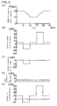
- Fig. 4 shows the energy balance of the electric motor vehicle of this embodiment
- Fig. 5 shows the energy balance of a conventional electric motor vehicle.
- the electric motor vehicles of this embodiment and the prior art have the same weight of 1000 kg, and a loss due to a running resistance when the vehicle is running is simplified to be a constant 5 kW regardless of the speed. And, the vehicles are accelerated or decelerated at an equal energy momentum of 30 kW.
- the allowable regenerative electric power of the storage battery at this moment is 10 kW, and this allowance corresponds to 100A of a storage battery of for example 100V and 200 Ah, falling in a state that the battery has discharged substantially. And, immediately after the complete charging, the allowable regenerative electric power is further decreased.
- Fig. 5 shows a travel speed of the electric motor vehicle
- a shows electric power consumed/outputted by a drive motor
- c shows energy consumption by a foot brake
- d shows electric power consumed by a compressor
- e shows outputted/charged electric power of a storage battery.
- the horizontal axis shows time common to these figures.
- the consumed/outputted power by the drive motor includes 5 kW at a constant-speed running, - 15 kW when decelerating, and 35 kW when accelerating.
- the storage battery outputs 10 kW which is a sum of the compressor consumption electric power and the running loss when the vehicle is running at a constant speed, charges 10 kW as described above when decelerating, and outputs 40 kW which is the sum total of the compressor consumption electric power, the running loss, and energy required for accelerating when the vehicle is accelerating.
- Fig. 4 shows a travel speed of the electric motor vehicle
- (b) shows electric power consumed/outputted by a drive motor
- (c) shows electric power consumed by a compressor
- (d) shows discharged/charged electric power of a storage battery.
- the horizontal axis shows time common to these figures.
- electric power of the drive motor shown in Fig. 4 (b) includes 5 kW at a constant-speed running, -15 kW when decelerating, and 35 kW when accelerating.
- the electric motor vehicle which is provided with the air conditioner and the drive motor which is driven by electric power supplied by the storage battery, is also provided with the power consumption indicator in which signals of the storage battery state and the regenerative state by a storage battery terminal voltmeter and the storage battery remaining capacity meter are inputted, and the air conditioner power adjusting device which increases the power of the air conditioner according to the instructions from the power consumption indicator, so that the power consumption by the air conditioner can be increased according to the storage battery state and the regeneration state.
- excess regenerative electric power which cannot be absorbed by the storage battery under regeneration can be used by the air conditioner. More specifically, since this excess regenerative electric power can be stocked as heat, electric power of the storage battery used by the air conditioner is saved to improve an energy efficiency, to extend a mileage per charge of the electric motor vehicle, and can reinforce the regenerative brake.
- the power consumption by the air conditioner when the vehicle is running normally is restricted to secure electric power for running with precedence over air conditioning, so that the electric motor vehicle whose mileage per charge can be extended can be realized.
- this embodiment can use the storage battery state detecting means and the regenerative electric power detecting means which are generally provided for the conventional electric motor vehicle, the addition of a simple control circuit to them can extend an actual mileage per charge inexpensively, and an electric motor vehicle whose regenerative brake contributing to safety has been reinforced can be produced.
- FIG. 6 is a control system diagram of this invention. As shown in Fig. 6, this embodiment is used for the air conditioner 1 in that electric power consumed by the compressor 2 is directly adjusted by a compressor power adjuster 22.
- reference numeral 23 represents a terminal voltmeter and 24 represents a storage battery reference voltage generator which generates the maximum allowable voltage of the storage battery 11. They respectively output a voltage signal and a reference voltage signal to a voltage comparator 25. According to these signals, a voltage difference is determined by the voltage comparator 25. And, when the storage battery voltage is higher or the regenerative electric power is excessively large, a consumed electric power indicating value corresponding to the difference is sent to a compressor power indicating signal switching device 26.
- the compressor power indicating signal switching device 26 switches a signal, which has entered the drive circuit 10 for the compressor 2 from the compressor power adjuster 22, into the consumed electric power signal from the voltage comparator.
- FIG. 7 shows the entire structure of an air conditioner for the electric motor vehicle according to this embodiment. Since the basic equipment configuration is the same as in the first embodiment, the same reference numerals are given to the same equipment.
- the air conditioner 1 of this embodiment has its principal pipe consisted in the following order of the compressor 2 connected by piping, the oil separator 3, the four-way valve 4, the exterior heat exchanger 5, two pairs of expansion valves 6, 7, the interior heat exchanger 8, and the accumulator 9. And, through these equipment, the refrigerant is designed to circulate in forward or reverse direction according to the cooling or heating mode of the air conditioner 1.
- a cabin heat accumulating means 30 is disposed on the air intake side of the interior heat exchanger 8, and dual circuit bypass pipes 31, 32 which lead the refrigerant into the cabin heat accumulating means 30 are connected via three-way valves 31a, 32a and check valves 31b, 32b which are respectively disposed on intake and outlet pipes of the interior heat exchanger 8.
- the compressor 2 is driven to compress by a built-in motor, and this motor has electric power supplied by the storage battery 11.
- the drive circuit 10 for driving the compressor 2 is connected to the electric power distribution device 14, and can be connected to the storage battery 11 or the drive circuit 12 for the drive motor 13 by the electric power distribution device 14. And, the electric power distribution device 14 is provided with the regenerative electric power detector 18.
- the air conditioner 1 if the regenerative brake is operated, the regenerative electric power detector 18 of the electric power distribution device 14 detects regenerative electric power. Then, the electric power distribution device 14 appropriately cuts off the storage battery 11 and the drive circuit 12 of the drive motor 13 according to a rechargeable condition of the storage battery 11, and appropriately connects the drive circuit 10 of the compressor 10 on the other hand, then controls a rotational frequency of the compressor 2, thereby recovering the regenerative electric power to the storage battery 11 and the compressor 2.
- the heat exchanging cycle when the air conditioner 1 operates to heat will be described.
- the refrigerant which is circulating within the air conditioner 1 is compressed by the compressor 2 and has an oil separated by the oil separator 3.
- the compressed refrigerant under high-temperature and high-pressure conditions is sent to the interior heat exchanger 8 by the four-way valve 4.
- the interior heat exchanger 8 is used to conduct the heat exchange of the air in the cabin to heat the cabin only by the condensed heating value of the compressed refrigerant. As a result, the compressed refrigerant is cooled into a liquid refrigerant.
- the electric power distribution device 14 controls the operation of the drive circuit 10 for the compressor 2 according to the excess electrical energy, and the drive circuit 10 increases the rotational frequency of the compressor 2. This control increases the flow rate of the refrigerant which is circulated during the heat exchange cycle, so that the heating capacity of the air conditioner 1 is enhanced.
- the air quantity by the air blower is kept constant or reduced. Therefore, an increased portion of the flow rate of the refrigerant is not cooled and discharged in a gaseous state from the interior heat exchanger 8.
- the passage of the refrigerant is switched by the three-way valve 32a to the passage to the cabin heat accumulating means 30.
- the refrigerant is lead to the cabin heat accumulating means 30 through the bypass pipe 32, and the condensed heat of the remaining gas refrigerant is accumulated in the cabin heat accumulating means 30.
- the refrigerant which is thoroughly cooled by the cabin heat accumulating means 30 passes through the three-way valve 32a in the forward direction to return to the principal pipe, and goes around the expansion valve 7 by the check valve 7a. Furthermore, the refrigerant is forced to pass through the expansion valve 6 by the check valve 6a, appropriately decreased in pressure by the expansion valve 6, and sent to the exterior heat exchanger 5. In the exterior heat exchanger 5, the refrigerant is fully heat-exchanged with the open air by an appropriate speed control of the air blower 5a and evaporated.
- the rotational frequency of the compressor 2 in the air conditioner 1 is generally controlled according to the cabin temperature.
- the operation frequency of the compressor 2 is lowered or stopped temporarily to avoid excessive heating, and the power consumption by the air conditioner 1 can be reduced.
- the discharge output of the storage battery 11 can be reduced temporarily after deceleration, a mileage per charge can be extended, and the service life of the storage battery 11 can be improved.
- the refrigerant is compressed by the compressor 2, and has an oil separated by the oil separator 3. Then, the compressed refrigerant under high-temperature and high-pressure conditions is sent to the exterior heat exchanger 5 by the four-way valve 4. And, the refrigerant is cooled by the air blower 5a in the exterior heat exchanger 5 into a liquid refrigerant. Then, the liquid refrigerant goes around the expansion valve 6 by the check valve 6a, and passes through the expansion valve 7 by the check valve 7a to be reduced in pressure appropriately.
- this decompressed refrigerant passes through the three-way valve 32a into the interior heat exchanger 8 without being lead into the cabin heat accumulating means 30 by the check valve 32b, is heat-exchanged with the air in the cabin and evaporated, passes through the four-way valve 4 and the accumulator 9, and is taken into the compressor 2.
- the air conditioner 1 when the vehicle is running normally, conducts the heat exchange with the air in the cabin only by the latent heat of vaporization of the gas-liquid refrigerant in the interior heat exchanger 8 to cool the cabin.
- the regenerative brake is operated by the deceleration of the vehicle, and the electric power distribution device 14 detects regenerative electric power. Then, in the same way as in the heating operation, the rotational frequency of the compressor 2 is increased, and the flow rate of the refrigerant circulated during the heat exchange cycle is increased, thereby enhancing the cooling capacity. To prevent excessive cooling, the air quantity by the air blower is kept constant or reduced, and an increased portion of the flow rate of the refrigerant is not evaporated and discharged in a gas-liquid state from the interior heat exchanger 8.
- the passage of the refrigerant is switched by the three-way valve 31a to lead the refrigerant into the cabin heat accumulating means 30 through the bypass pipe 31, and the latent heat of vaporization of the remaining gas-liquid refrigerant is accumulated in the cabin heat accumulating means 30.
- the refrigerant which is thoroughly evaporated by the cabin heat accumulating means 30 is returned to the principal pipe through the check valve 31b, passed through the four-way valve 4 and the accumulator 9, and taken into the compressor 2.
- the operation frequency of the compressor 2 is lowered or stopped temporarily to avoid excessive cooling, and at the same time the power consumption by the air conditioner can be reduced.
- the output value of the storage battery 11 after regeneration can be reduced, a mileage per charge can be extended, and the service life of the storage battery 11 can be elongated.
- the same effect as described above can be obtained by structuring the bypass pipe 31 and the bypass pipe 32 so that the refrigerant on the intake side of the interior heat exchanger 8 can be introduced, or by combining the bypass pipe 31 and the bypass pipe 32 into one bypass pipe, and by directly introducing the compressed refrigerant or gas-liquid refrigerant into the cabin heat accumulating means 30 according to the control of supplying the refrigerant by the detection of regenerative electric power in the same way as described above, the same effect as described above can be obtained.
- this embodiment relates to an electric motor vehicle which is provided with the air conditioner and the drive motor which are driven by the electric power supplied by the storage battery, and the electric power distribution device for distributing the electric power to them; the heat accumulating means for introducing the refrigerant at either the outlet or inlet side of the interior heat exchanger is disposed on the interior heat exchanger of the air conditioner; or the heat accumulating means for introducing the refrigerant at either the outlet or inlet side of the interior heat exchanger of the exterior heat exchanger is disposed; and a refrigerant passage control valve for controlling the supply of the refrigerant to the respective heat accumulating means according to the detection of the regenerative electric power of the electric power distribution device is provided.
- the electric power distribution device cuts off the storage battery and the motor completely or appropriately to utilize all or part of the regenerative electric power from the regenerative brake as driving electric power of the compressor 2 in the air conditioner.
- the cooling and heating capacity can be enhanced.
- the quantity of heat corresponding to the excess portion of cooling or heating is accumulated in the heat accumulating means and used to adjust or improve the cooling or heating capacity in the cabin, or used as the heat of evaporation of the refrigerant in the heat exchange cycle in winter, thereby making it possible to effectively use without waste the regenerative electric power which heretofore could not be recovered mostly by the storage battery only.
- energy balance can be made highly efficient.
- the temperature of the air blown from the interior heat exchanger because of the aforementioned operation is raised, and heating can be completed quickly and at high efficiency. Since the refrigerant is evaporated easily and completely by the exterior heat exchanger, lowering of the evaporating capacity due to adhesion of frost and a puddle of the refrigerant can be prevented, and the speed of the air blower can be reduced. As a result, the electric power of the storage battery used by the air conditioner can be saved, and the waste consumption of the storage battery can be avoided. Therefore, an electric motor vehicle whose mileage per charge is improved and which is provided with an air conditioner system having a high total energy efficiency can be provided.
- FIG. 8 shows the entire structure of the air conditioner 1 of the electric motor vehicle of this embodiment.
- the air conditioner 1 has the same basic structure as described in the third embodiment, and the same equipment are given the same reference numerals.
- the electric power distribution operation when the regenerative electric power is detected by the regenerative electric power detector 18 provided on the electric power distribution device 14 and the control of the rotational frequency of the motor built in the compressor 2 are the same as in the third embodiment.
- a difference from the above embodiment is that a dual-circuit heat accumulating means is provided.
- the cabin heat accumulating means 30 is disposed on the air intake side of the interior heat exchanger 8, and an exterior heat accumulating means 34 on the air intake side of the exterior heat exchanger 5, respectively.
- the bypass pipe 31 for leading the refrigerant into the cabin heat accumulating means 30 is connected via the three-way valve 31a and the check valve 31b which are disposed on the pipe on the four-way valve side of the interior heat exchanger 8.
- a bypass pipe 35 for leading the refrigerant into the exterior heat accumulating means 34 is connected via the three-way valve 35a and the check valve 35b which are disposed on the pipe on the expansion valve side of the interior heat exchanger 8.
- the heat exchange cycle for the heating operation in this embodiment will be described.
- the flow of the refrigerant in the heat exchange cycle and the cabin heating method by the air conditioner 1 when the vehicle is running normally are the same as in the above embodiment.
- the control of an increase of the rotational frequency of the compressor 2 according to an excessive charging quantity to the storage battery 11 when the electric power distribution device 14 detects the regenerative electric power is also the same as in the third embodiment.
- the flow rate of the refrigerant circulated during the heat exchange cycle increases and the heating capacity is increased, but the air quantity by the air blower 8a for preventing over-heating is kept constant or reduced, and an increased portion of the flow rate of the refrigerant is not cooled and discharged in a gaseous state from the interior heat exchanger 8.
- switching of the refrigerant passage by the three-way valve 35a leads the refrigerant to the exterior heat accumulating means 34 through the bypass pipe 35, and the condensed heat of the remaining gas refrigerant is accumulated in the exterior heat accumulating means 34.
- the refrigerant thoroughly cooled by the exterior heat accumulating means 34 is returned to the principal pipe through the check valve 35b, passed through the check valve 7a in the forward direction, detoured around the expansion valve 7, passed through the expansion valve 6 by the operation of the check valve 6a to be decompressed appropriately, and sent to the exterior heat exchanger 5.
- the rotating speed of the air blower 5a is suitably controlled to make sufficient heat exchange with the open air to evaporate the refrigerant, which is then passed through the four-way valve 4 and the accumulator 9, and taken into the compressor 2.
- the exterior heat accumulating means 34 gradually hold a large quantity of heat.
- higher temperature air than when the vehicle is running normally is sent to the exterior heat exchanger 5 by the air blower 5a, a temperature difference form the evaporating temperature of the gas-liquid refrigerant increases, making the evaporation of the refrigerant easy.
- the steep decrease of the refrigerant evaporating load in the exterior heat exchanger 5 makes it unnecessary to decrease to an extremely low evaporating temperature as in the prior art, and the blowing air quantity by the air blower 5a can be reduced significantly.
- the power consumption is reduced and the total energy efficiency is improved, making it possible to extend a mileage per charge and the service life of the storage battery 11.
- the third and fourth embodiments can be realized to operate in the heat exchange cycle of the same air conditioner.
- the refrigerant which cannot be condensed is supplied to the cabin heat accumulating means 30 and the exterior heat accumulating means 34 to enhance the heating of the cabin interior and, at the same time, to accelerate the evaporation of the refrigerant in the exterior heat exchanger 5. Therefore, the power consumption by the compressor 2 and the air blowers 5a, 8a can be reduced, and the air conditioning system with higher energy efficiency can be obtained.
- the same effect as described above can be attained by configuring the bypass pipe 35 of the exterior heat accumulating means 34 so that the refrigerant on the inlet side of the interior heat exchanger 8 can be introduced, and by directly introducing the compressed refrigerant into the exterior heat accumulating means 34 according to the same control of the refrigerant supply according to the detection of the regenerative electric power as described above.
- the air conditioner is operated only for the recovery of the regenerative electric power to consume excessive regenerative electric power as the driving electric power for the compressor and the air blower, and the blowing is controlled to discharge the hot or cool air of the interior heat exchanger from the cabin.
- the air conditioner can be used not only for the heat exchange cycle to recover and use the regenerative electric power, but also for protecting the storage battery, and further used as a discarding means of the regenerative electric power which reinforces the regenerative brake.
- this invention in the electric motor vehicle which is provided with the air conditioner and the electric power distribution device using a motor as the driving source, disposes the heat accumulating means for introducing the refrigerant at either the outlet or inlet side of the interior heat exchanger on the interior heat exchanger, or disposes the heat accumulating means for introducing the refrigerant at either the outlet or inlet side of the interior heat exchanger of the exterior heat exchanger, and provides a control device for supplying the refrigerant to the respective heat accumulating means in the form of a refrigerant passage control valve which operates according to the detection of the regenerative electric power of the electric power distribution device.
- the electric power distribution device cuts off the storage battery and the motor completely or appropriately to utilize all or part of the regenerative electric power as the compressor driving power of the air conditioner.
- the quantity of heat corresponding to the excess portion of cooling and heating is accumulated in the heat accumulating means and used to adjust or improve the cooling and heating capacity in the cabin, or used as the heat of evaporation of the refrigerant in the heat exchange cycle in winter, thereby making it possible to effectively use without waste the regenerative electric power which heretofore could not be recovered mostly by the storage battery only.
- energy balance can be made highly efficient.
- the temperature of the air blown from the interior heat exchanger by the aforementioned operation is raised, and the cabin heating can be completed quickly and at high efficiency, thereby improving the air conditioning environment.
- the refrigerant is evaporated easily and completely by the exterior heat exchanger, lowering of the evaporating capacity due to adhesion of frost and a puddle of the refrigerant can be prevented, and the rotating speed of the air blower can be reduced by lowering the blowing air quantity.
- the electric power of the storage battery used by the air conditioner can be saved, and the waste consumption of the storage battery can be avoided. Therefore, an electric motor vehicle whose mileage per charge is improved and which is provided with an air conditioner having a high total energy efficiency can be provided.
- FIG. 9 shows the entire structure of the air conditioner 1 used for the electric motor vehicle of this embodiment.
- the air conditioner 1 consists in the following order of the compressor 2 connected by piping, the oil separator 3, the four-way valve 4, the exterior heat exchanger 5, two pairs of expansion valves 6, 7, the interior heat exchanger 8, and the accumulator 9. And, when this air conditioner 1 is operating, the refrigerant is forcedly fed by the compressor 2, and circulated in the forward or reverse direction within these equipment according to the switching operation of the four-way valve 4 according to the cooling or heating operation of the air conditioner 1.
- the compressor 2 is driven by the built-in motor to compress the refrigerant, and the motor receives the electric power from the storage battery 11.
- the storage battery 11 is connected to the drive motor 13 for running the electric motor vehicle through the drive circuit 12, and supplies discharge electric power according to the vehicle speed.
- the electric power distribution device 14 is disposed between the storage battery 11 and the drive circuit 12.
- the drive motor 13 is temporarily used as the generator to convert kinetic energy for a decelerated speed into electrical energy.
- the regenerative brake for recovering the energy as the regenerative electric power is configured.
- resistor 41 disposed within the interior heat exchanger 8
- resistor 42 disposed within the exterior heat exchanger 5.
- the connection terminal of at least one of these resistors 41, 42 can be connected to the drive circuit 12 of the drive motor 13 through the electric power distribution device 14 but not directly connected to the storage battery 11.
- the electric power distribution device 14 is provided with the regenerative electric power detector 18 and operates only when the air conditioner 1 is in the heating operation mode. Specifically, when the air conditioner 1 is operating in the heating mode and the electric motor vehicle is running normally, the storage battery 11 is connected with the drive circuit 12, while the resistors 41, 42 are cut off from the storage battery 11 and the drive circuit 12. In this case, when the regenerative brake operates to generate regenerative electric power to decelerate the electric motor vehicle, the regenerative electric power is detected by the regenerative electric power detector 18 of the electric power distribution device 14. And, the electric power distribution device 14 cuts off the storage battery 11 and the drive circuit 12, and connects at least one of the resistors 41, 42 with the drive circuit. Thus, excess regenerative electric power can be recovered as heat into the heat recovery circuits.
- the steam refrigerant under high-temperature and high-pressure conditions after being compressed by the compressor 2 and having an oil separated by the oil separator 3 is sent to the interior heat exchanger 8 by the four-way valve 4.
- the cabin is heated by effecting the heat exchange with the air in the cabin only by the condensed heating value of the compressed refrigerant in the interior heat exchanger 8, so that the compressed refrigerant is cooled into a liquid refrigerant.
- the regenerative electric power generated by the drive motor 13 is sent to at least one of the resistors 41 and 42 through the electric power distribution device 14, and the resistors 41 and 42 generate heat to heat the interior heat exchanger 8 or the exterior heat exchanger 5.
- the resistor 41 on the heat recovery circuit disposed on the interior heat exchanger 8 is specifically attached to the pipe at the refrigerant inlet section of a heat exchange section or the interior heat exchanger 8.
- the heat exchange section of the interior heat exchanger 8 is gradually heated by the heat obtained by converting the regenerative electric power, and the compressed refrigerant to be introduced into the interior heat exchanger 8 is heated, so that the compressed refrigerant has a temperature higher than when discharged from the compressor 2, and enthalpy is raised.
- the air to be sent into the interior heat exchanger 8 is heated more than when the vehicle is running normally, and a temperature of the air blown out by the interior heat exchanger 8 into the cabin rises to improve the heating capacity of the air conditioner 1.
- the rotating speed of the motor which drives the compressor 2 in the air conditioner 1 is generally controlled according to the cabin temperature.
- the heating capacity is improved by using the regenerative electric power for the air conditioner 1
- the motor of the compressor 2 can be temporarily stopped or its rotating speed can be lowered.
- excessive heating of the cabin is prevented, and the power consumption by the air conditioner 1 is temporarily reduced, thereby making it possible to lower the discharge output value of the storage battery after regeneration.
- a mileage per charge can be extended, and the service life of the storage battery 11 can be improved.
- the refrigerant which is cooled and liquefied by the heat exchange in the interior heat exchanger 8 is detoured around the expansion valve 7 by the check valve 7a, and sent to the exterior heat exchanger 5 through the expansion valve 6.
- the refrigerant is inevitably passed through the expansion valve 6 by the check valve 6a, appropriately decompressed into a gas-liquid refrigerant at a low temperature, and sent to the exterior heat exchanger 5.
- the exterior heat exchanger 5 has the resistor 42 attached in the same way as the resistor 41 of the interior heat exchanger 8 described above. And, when the regenerative brake is operated, excess regenerative electric power is supplied to the resistor 42. Heat generated by the resistor 42 gradually heats the heat exchange section of the exterior heat exchanger 5 or the refrigerant pipe lead to the exterior heat exchanger 5. Therefore, the gas-liquid refrigerant in the exterior heat exchanger 5 is evaporated easily and completely. Thus, since an evaporation load of the main body of the exterior heat exchanger 5 can be reduced significantly, an extremely low evaporation temperature as in the prior art is not needed, and the air quantity by the air blower 5a can be also reduced significantly. Accordingly, the total electric power of the storage battery consumed by the air conditioner 1 can be saved.
- the electric power distribution device 14 may be provided with the terminal voltmeter 23 of the storage battery or the storage battery remaining capacity meter 11a as a charging state monitoring device to judge an allowable regenerative electrical energy to the storage battery.
- a discharge voltage of the storage battery is lower than a prescribed voltage, charging is made by the regenerative electric power, and when it is higher, the regenerative electric power can be distributed to the resistors 41, 42 of the heat recovery circuit.
- the distribution of the regenerative electric power to the resistors 41, 42 of the heat recovery circuit can be set voluntarily by changing the resistance values of the resistors and by changing an electrifying time by the addition of a switch or the like.
- Fig. 10 shows a speed of the electric motor vehicle
- Fig. 10 shows electric power consumed/outputted by the drive motor
- c shows the recovered energy by the resistor
- d shows the electric power consumed by the compressor
- e shows the discharged/outputted electric power of the storage battery.
- the horizontal axis shows time common to these figures.
- the output of the drive motor shown in Fig. 10 (b) includes 5 kW when running at a constant speed, -25 kW when decelerating, and 35 kW when accelerating.
- the generated electric power by the drive motor when the vehicle is decelerating is greater than in the prior art, because total kinetic energy to be reduced when decelerating is converted into electrical energy and absorbed.
- excess electrical energy which cannot be recovered by the storage battery is accumulated as heat energy in the interior heat exchanger or the exterior heat exchanger by means of the resistor.
- the charging quantity into the storage battery when regenerating is limited to electrical energy of 15 kW which does not put an extra strain on the storage battery in the same way as in the prior art.
- the compressor of the air conditioner can be stopped temporarily after the completion of deceleration.
- the discharge output of the storage battery is lowered corresponding to the consumed electric power of the compressor which is stopped temporarily, and the power consumption is reduced for a given time, reducing an integral.
- high current discharge has adverse effects such as shortening the service life and lowering a discharge efficiency.
- Such high current discharge is required to accelerate the vehicle immediately after decelerating which is often used in the general running conditions of the electric motor vehicle.
- the present invention does not require the power consumption by the compressor and reduces a burden applied to the storage battery, providing the storage battery with remarkable effects of a high discharge efficiency and a long service life.
- this embodiment in the electric motor vehicle which is provided with the air conditioner and the drive motor driven by the electric power from the storage battery, provides the motor and at least one of the interior heat exchanger and the exterior heat exchanger with a resistor, the heat recovery circuit with the above resistor connected to the electric power distribution device for distributing the electric power from the storage battery, and the regenerative electric power detecting device or the charging state monitoring device of the storage battery on the electric power distribution device.
- the regenerative brake when the regenerative brake is operated with the air conditioner operated for heating, the storage battery and the motor are cut off completely or appropriately, all or part of the regenerative electric power generated by the regenerative brake is converted into heat by the resistor in the cabin to heat the interior heat exchanger, thereby improving the cabin heating capacity, or supplying the heat by a resistor located outside the cabin to the exterior heat exchanger which operates as a refrigerant evaporating means in the heat exchange cycle for heating to accelerate the evaporation of the refrigerant.
- the regenerative electric power which heretofore could not be recovered mostly by the storage battery only can be used effectively without waste, attaining highly efficient utilization of energy as the entire electric motor vehicle.
- the temperature of the air blown from the interior heat exchanger by the aforementioned operation is raised, and the cabin heating can be made quickly and efficiency.
- the refrigerant is evaporated easily and completely by the exterior heat exchanger, lowering of the evaporating capacity and the heating capacity due to adhesion of frost and a puddle of the refrigerant can be prevented.
- efficiency and reliability are enhanced by significantly reducing the air quantity by a fan, so that the electric power of the storage battery consumed by the air conditioner can be saved, and the waste consumption of the storage battery can be avoided.
- a mileage per charge can be extended by the effective utilization of the regenerative electric power.
- an electric motor vehicle provided with a heating system having a high total energy efficiency can be obtained.
- charging electric power according to the consumed state of the storage battery at that point can be always assigned to the storage battery, so that the storage battery can be preserved and protected, its service life can be elongated, and the charging and discharging capacity can be maintained.
- this invention can realize an air conditioner which saves the power consumption of a storage battery and operates at a high efficiency by using the regenerative electric power of a regenerative brake.
- it is suitable for an electric motor vehicle which is provided with the regenerative brake and the air conditioner.
Applications Claiming Priority (7)
| Application Number | Priority Date | Filing Date | Title |
|---|---|---|---|
| JP62020/93 | 1993-03-22 | ||
| JP6201993 | 1993-03-22 | ||
| JP62019/93 | 1993-03-22 | ||
| JP6202093 | 1993-03-22 | ||
| JP78302/93 | 1993-04-05 | ||
| JP7830293 | 1993-04-05 | ||
| PCT/JP1994/000450 WO1994021481A1 (en) | 1993-03-22 | 1994-03-18 | Electric vehicle |
Publications (3)
| Publication Number | Publication Date |
|---|---|
| EP0640503A1 true EP0640503A1 (de) | 1995-03-01 |
| EP0640503A4 EP0640503A4 (de) | 1995-07-26 |
| EP0640503B1 EP0640503B1 (de) | 1998-09-23 |
Family
ID=27297715
Family Applications (1)
| Application Number | Title | Priority Date | Filing Date |
|---|---|---|---|
| EP94910051A Expired - Lifetime EP0640503B1 (de) | 1993-03-22 | 1994-03-18 | Elektrisches fahrzeug |
Country Status (5)
| Country | Link |
|---|---|
| US (1) | US5507153A (de) |
| EP (1) | EP0640503B1 (de) |
| JP (1) | JP3353299B2 (de) |
| DE (1) | DE69413481T2 (de) |
| WO (1) | WO1994021481A1 (de) |
Cited By (15)
| Publication number | Priority date | Publication date | Assignee | Title |
|---|---|---|---|---|
| ES2152844A1 (es) * | 1998-08-28 | 2001-02-01 | Urroz Eduardo Romo | Freno electrico por acumulacion para vehiculos ferroviarios. |
| FR2814399A1 (fr) * | 2000-09-22 | 2002-03-29 | Sanden Corp | Systeme de climatisation pour vehicules |
| WO2002053406A1 (de) * | 2000-12-29 | 2002-07-11 | Siemens Aktiengesellschaft | Kraftfahrzeug mit einem elektromotorantrieb und einer bordstromversorgung |
| FR2820369A1 (fr) | 2001-02-08 | 2002-08-09 | Renault | Vehicule automobile equipe d'un systeme de climatisation et procede de commande d'un tel systeme |
| EP1236595A1 (de) * | 2001-02-16 | 2002-09-04 | Kabushiki Kaisha Toyota Jidoshokki | Kraftfahrzeugklimatisierungssystem und entsprechendes Verfahren |
| EP2026443A3 (de) * | 2007-08-03 | 2009-04-29 | Iveco Motorenforschung AG | Verfahren und System zum Speichern von Energie in einem Fahrzeug |
| EP2020729A3 (de) * | 2007-08-03 | 2009-04-29 | Iveco Motorenforschung AG | Verfahren und System zum Speichern von Energie |
| WO2010071540A1 (en) * | 2008-12-15 | 2010-06-24 | Electroengine In Sweden Ab | Electric motor driven vehicle, production kit for producing an electric motor driven vehicle, and a method of producing an electric motor driven vehicle |
| CN102343823A (zh) * | 2010-06-14 | 2012-02-08 | 通用汽车环球科技运作有限责任公司 | 用于控制车辆制动的方法和系统 |
| WO2012150070A1 (de) * | 2011-05-05 | 2012-11-08 | Bayerische Motoren Werke Aktiengesellschaft | Verfahren zum konditionieren eines wärme-/kältespeichers sowie fahrzeug mit einem wärme-/kältespeicher |
| EP2525994A2 (de) * | 2010-01-19 | 2012-11-28 | Continental Automotive GmbH | Fahrzeug mit elektrischem antrieb |
| EP2719572A4 (de) * | 2011-06-07 | 2016-03-02 | Toyota Motor Co Ltd | Elektrofahrzeug und steuerungsverfahren für ein elektrofahrzeug |
| EP3061635A1 (de) * | 2015-02-27 | 2016-08-31 | MAHLE International GmbH | Hlk-system zur fahrreichweitenerweiterung eines elektrofahrzeugs |
| WO2017182924A1 (en) * | 2016-04-18 | 2017-10-26 | Politechnika Lubelska | A method and system for storing heat or cold in vehicles with electric propulsion |
| WO2023097209A1 (en) * | 2021-11-29 | 2023-06-01 | Caterpillar Global Mining Equipment Llc | Brake control system for battery-powered machine |
Families Citing this family (56)
| Publication number | Priority date | Publication date | Assignee | Title |
|---|---|---|---|---|
| US6755032B1 (en) * | 2000-01-13 | 2004-06-29 | Ford Global Technologies, Inc. | Control method for a vehicle having an engine and an accessory device |
| US6349561B1 (en) * | 2000-02-24 | 2002-02-26 | Visteon Global Technologies, Inc. | Refrigeration circuit for vehicular air conditioning system |
| JP2003074476A (ja) * | 2001-08-31 | 2003-03-12 | Nippon Soken Inc | 圧縮機制御装置 |
| JP3745677B2 (ja) * | 2001-11-19 | 2006-02-15 | 株式会社デンソー | 車両用回生制動装置 |
| JP4060142B2 (ja) * | 2002-07-30 | 2008-03-12 | 本田技研工業株式会社 | 車両用空調装置 |
| KR100527184B1 (ko) | 2003-07-07 | 2005-11-08 | 현대자동차주식회사 | 전기자동차의 공조 시스템을 이용한 회생 제동 방법 |
| US7600391B2 (en) * | 2004-09-10 | 2009-10-13 | Gm Global Technology Operations, Inc. | Coolant-based regenerative energy recovery system |
| JP4585842B2 (ja) * | 2004-12-10 | 2010-11-24 | 株式会社日立製作所 | 車両電気駆動装置 |
| JP2006149023A (ja) * | 2004-11-17 | 2006-06-08 | Nissan Motor Co Ltd | 電動車両の負荷制御装置 |
| DE102005018434A1 (de) * | 2005-04-21 | 2006-10-26 | Continental Aktiengesellschaft | Kraftfahrzeug mit einer pneumatischen Niveauregelanlage |
| CN100411905C (zh) * | 2006-03-23 | 2008-08-20 | 上海瑞华(集团)有限公司 | 一种混合电能超级电容车动力系统总成 |
| KR101297925B1 (ko) * | 2006-08-10 | 2013-08-19 | 미쓰비시덴키 가부시키가이샤 | 전기차의 제어 장치 |
| JP4984808B2 (ja) * | 2006-10-10 | 2012-07-25 | トヨタ自動車株式会社 | 空調制御システム |
| US8547055B2 (en) * | 2007-03-14 | 2013-10-01 | Ford Global Technologies, Llc | Method and apparatus to control electric power consumption |
| SE0701183L (sv) * | 2007-05-15 | 2008-12-23 | Scania Cv Ab | Värmesystem för användning i ett fordon |
| JP5018489B2 (ja) * | 2007-07-26 | 2012-09-05 | 株式会社エクォス・リサーチ | 車載空調システム |
| US20090064696A1 (en) * | 2007-09-11 | 2009-03-12 | Ford Global Technologies, Llc | Automotive climate system and method of controlling same |
| US8215432B2 (en) * | 2008-05-09 | 2012-07-10 | GM Global Technology Operations LLC | Battery thermal system for vehicle |
| JP4686572B2 (ja) * | 2008-05-14 | 2011-05-25 | 住友重機械工業株式会社 | クライオポンプ、真空排気システム、及びその診断方法 |
| DE102009000115A1 (de) * | 2009-01-09 | 2010-07-15 | Robert Bosch Gmbh | Vorrichtung zum Energiemanagement eines Fahrzeugs |
| JP5380253B2 (ja) * | 2009-11-18 | 2014-01-08 | 株式会社日立製作所 | 電動車両の制御システムと該制御システムを搭載した電動車両 |
| JP2011178309A (ja) * | 2010-03-02 | 2011-09-15 | Denso Corp | 車両用空調装置 |
| JP5510730B2 (ja) * | 2010-07-12 | 2014-06-04 | 株式会社デンソー | 車両用空調制御システム |
| US8483897B2 (en) | 2010-08-13 | 2013-07-09 | GM Global Technology Operations LLC | Vehicular propulsion systems and methods for managing the same |
| JP5659925B2 (ja) * | 2011-04-04 | 2015-01-28 | 株式会社デンソー | 車両用空調装置 |
| WO2012157049A1 (ja) * | 2011-05-13 | 2012-11-22 | トヨタ自動車 株式会社 | 空調装置の制御装置 |
| DE102011107540B4 (de) | 2011-07-16 | 2013-05-23 | Audi Ag | Verfahren zum Betreiben eines Kraftwagens in einem Sportbetriebsmodus |
| JP5743109B2 (ja) * | 2012-12-18 | 2015-07-01 | 三菱自動車工業株式会社 | 冷媒循環装置 |
| WO2014109103A1 (ja) * | 2013-01-08 | 2014-07-17 | クラリオン株式会社 | 空調制御装置および空調制御方法 |
| DE102013202512B4 (de) | 2013-02-15 | 2016-07-21 | Continental Automotive Gmbh | Verfahren zur Steuerung von der Rekuperationsleistung eines rekuperationsfähigen Antriebs sowie Vorrichtung hierfür |
| KR101509944B1 (ko) * | 2013-10-22 | 2015-04-07 | 현대자동차주식회사 | 에어컨 제어방법 |
| JP2015098291A (ja) * | 2013-11-20 | 2015-05-28 | トヨタ自動車株式会社 | ハイブリッド車両の制御装置 |
| US9823009B2 (en) * | 2014-03-14 | 2017-11-21 | Ford Global Technologies, Llc | Method and system for de-icing a heat exchanger |
| EP3196061B1 (de) * | 2014-07-30 | 2020-09-16 | Creatio Irizar Group Innovation Center Aie | Personenkraftwagen |
| US10086818B2 (en) | 2015-01-07 | 2018-10-02 | GM Global Technology Operations LLC | Systems and methods for managing vehicular energy consumption |
| CN105196832A (zh) * | 2015-09-30 | 2015-12-30 | 上海交通大学 | 充量自动调节的电动汽车废热回收热泵式综合热管理系统 |
| US9878703B2 (en) | 2016-03-08 | 2018-01-30 | Ford Global Technologies, Llc | Electrified vehicle with power dissipation feature |
| JP6468259B2 (ja) | 2016-08-02 | 2019-02-13 | トヨタ自動車株式会社 | 車両用制御システム |
| DE102017204116B4 (de) | 2017-03-13 | 2022-06-15 | Audi Ag | Kälteanlage eines Fahrzeugs mit einem als Kältekreislauf für einen Kältebetrieb und als Wärmepumpenkreislauf für einen Heizbetrieb betreibbaren Kältemittelkreislauf |
| US10428713B2 (en) | 2017-09-07 | 2019-10-01 | Denso International America, Inc. | Systems and methods for exhaust heat recovery and heat storage |
| CN107867200A (zh) * | 2017-12-08 | 2018-04-03 | 珠海长欣汽车智能系统有限公司 | 一种带油分的汽车温控系统 |
| JP6584019B2 (ja) * | 2017-12-21 | 2019-10-02 | 本田技研工業株式会社 | 電動車両 |
| JP6570200B2 (ja) * | 2017-12-21 | 2019-09-04 | 本田技研工業株式会社 | 電動車両 |
| JP6584020B2 (ja) * | 2017-12-21 | 2019-10-02 | 本田技研工業株式会社 | 電動車両 |
| US11833884B2 (en) * | 2018-04-20 | 2023-12-05 | Mitsubishi Electric Corporation | Heat exchange system for vehicle and air conditioning system for vehicle |
| US10392018B1 (en) * | 2018-09-27 | 2019-08-27 | Ford Global Technologies, Llc | Vehicle and regenerative braking control system for a vehicle |
| KR102600059B1 (ko) * | 2018-12-03 | 2023-11-07 | 현대자동차 주식회사 | 차량용 열 관리 시스템 |
| US10889158B2 (en) | 2019-02-04 | 2021-01-12 | Ford Global Technologies, Llc | Motor vehicle including a climate control system with accumulator, and corresponding method |
| JP7245131B2 (ja) * | 2019-07-16 | 2023-03-23 | 株式会社日本クライメイトシステムズ | 車両用蓄熱システム |
| WO2022018393A1 (en) * | 2020-07-24 | 2022-01-27 | Avid Technology Limited | Energy storage and release in an electric vehicle |
| KR20220021201A (ko) * | 2020-08-13 | 2022-02-22 | 현대자동차주식회사 | 차량용 열 관리 시스템 |
| US11571944B2 (en) | 2020-11-24 | 2023-02-07 | Fca Us Llc | Electric vehicle thermal system with waste heat recovery |
| EP4347329A1 (de) * | 2021-06-04 | 2024-04-10 | Volvo Truck Corporation | Energieverwaltungssystem, brennstoffzellensystem, fahrzeug und verfahren zur steuerung eines energieverwaltungssystems |
| EP4113704A1 (de) * | 2021-06-29 | 2023-01-04 | Volvo Truck Corporation | Kühlsystem und verfahren zur steuerung eines kühlsystems |
| US11912167B2 (en) * | 2022-01-20 | 2024-02-27 | Hyundai Translead | Regenerative retarder energy system for trailers |
| EP4358334A1 (de) * | 2022-10-18 | 2024-04-24 | Volvo Truck Corporation | Verfahren zur steuerung einer elektrischen stromquelle |
Citations (3)
| Publication number | Priority date | Publication date | Assignee | Title |
|---|---|---|---|---|
| DE1035190B (de) * | 1952-11-15 | 1958-07-31 | Bbc Brown Boveri & Cie | Verfahren zur Nutzbremsung fuer aus einer Wechselstromfahrleitung gespeiste und ueber Stromrichter mit Gleichstrom-motoren betriebene Fahrzeuge |
| EP0537873A1 (de) * | 1991-10-16 | 1993-04-21 | MANNESMANN Aktiengesellschaft | Nicht-spurgebundenes Fahrzeug mit Elektromotor-Antrieb und Nutzbremsung |
| EP0611675A1 (de) * | 1993-02-15 | 1994-08-24 | SMH Management Services AG | Fahrzeug mit elektrischem Antrieb mit einer Vorrichtung zur Rückgewinnung der Energie |
Family Cites Families (11)
| Publication number | Priority date | Publication date | Assignee | Title |
|---|---|---|---|---|
| US3918543A (en) * | 1973-12-26 | 1975-11-11 | Norman Halem | System for employing the change of momentum during vehicle deceleration for accessory power |
| US4345197A (en) * | 1980-03-03 | 1982-08-17 | General Motors Corporation | Vehicle battery charging system |
| JPS5784214A (en) * | 1980-11-12 | 1982-05-26 | Hitachi Ltd | Motorcar air-conditioner and its driving method |
| JPS59102617A (ja) * | 1982-12-03 | 1984-06-13 | Diesel Kiki Co Ltd | 車輌の冷房システムの制御方法 |
| US4536697A (en) * | 1983-09-09 | 1985-08-20 | General Motors Corporation | Vehicle electrical energy management system |
| JPS6165802A (ja) * | 1984-09-10 | 1986-04-04 | Maruzen Kasei Kk | 保存料 |
| JPS6165802U (de) * | 1984-10-05 | 1986-05-06 | ||
| KR100201267B1 (ko) * | 1990-05-16 | 1999-06-15 | 가와모토 노부히코 | 전동차량의 회생제동장치 |
| JPH0488301A (ja) * | 1990-08-01 | 1992-03-23 | Canon Inc | 偏光変換モジュール |
| JPH0488301U (de) * | 1990-11-30 | 1992-07-31 | ||
| JP3154514B2 (ja) * | 1991-05-31 | 2001-04-09 | 本田技研工業株式会社 | 車両のブレーキ装置 |
-
1994
- 1994-03-18 EP EP94910051A patent/EP0640503B1/de not_active Expired - Lifetime
- 1994-03-18 JP JP52087894A patent/JP3353299B2/ja not_active Expired - Lifetime
- 1994-03-18 DE DE69413481T patent/DE69413481T2/de not_active Expired - Lifetime
- 1994-03-18 WO PCT/JP1994/000450 patent/WO1994021481A1/ja active IP Right Grant
- 1994-03-18 US US08/338,467 patent/US5507153A/en not_active Expired - Lifetime
Patent Citations (3)
| Publication number | Priority date | Publication date | Assignee | Title |
|---|---|---|---|---|
| DE1035190B (de) * | 1952-11-15 | 1958-07-31 | Bbc Brown Boveri & Cie | Verfahren zur Nutzbremsung fuer aus einer Wechselstromfahrleitung gespeiste und ueber Stromrichter mit Gleichstrom-motoren betriebene Fahrzeuge |
| EP0537873A1 (de) * | 1991-10-16 | 1993-04-21 | MANNESMANN Aktiengesellschaft | Nicht-spurgebundenes Fahrzeug mit Elektromotor-Antrieb und Nutzbremsung |
| EP0611675A1 (de) * | 1993-02-15 | 1994-08-24 | SMH Management Services AG | Fahrzeug mit elektrischem Antrieb mit einer Vorrichtung zur Rückgewinnung der Energie |
Non-Patent Citations (1)
| Title |
|---|
| See also references of WO9421481A1 * |
Cited By (19)
| Publication number | Priority date | Publication date | Assignee | Title |
|---|---|---|---|---|
| ES2152844A1 (es) * | 1998-08-28 | 2001-02-01 | Urroz Eduardo Romo | Freno electrico por acumulacion para vehiculos ferroviarios. |
| FR2814399A1 (fr) * | 2000-09-22 | 2002-03-29 | Sanden Corp | Systeme de climatisation pour vehicules |
| WO2002053406A1 (de) * | 2000-12-29 | 2002-07-11 | Siemens Aktiengesellschaft | Kraftfahrzeug mit einem elektromotorantrieb und einer bordstromversorgung |
| FR2820369A1 (fr) | 2001-02-08 | 2002-08-09 | Renault | Vehicule automobile equipe d'un systeme de climatisation et procede de commande d'un tel systeme |
| EP1236595A1 (de) * | 2001-02-16 | 2002-09-04 | Kabushiki Kaisha Toyota Jidoshokki | Kraftfahrzeugklimatisierungssystem und entsprechendes Verfahren |
| EP2026443A3 (de) * | 2007-08-03 | 2009-04-29 | Iveco Motorenforschung AG | Verfahren und System zum Speichern von Energie in einem Fahrzeug |
| EP2020729A3 (de) * | 2007-08-03 | 2009-04-29 | Iveco Motorenforschung AG | Verfahren und System zum Speichern von Energie |
| WO2010071540A1 (en) * | 2008-12-15 | 2010-06-24 | Electroengine In Sweden Ab | Electric motor driven vehicle, production kit for producing an electric motor driven vehicle, and a method of producing an electric motor driven vehicle |
| EP2525994A2 (de) * | 2010-01-19 | 2012-11-28 | Continental Automotive GmbH | Fahrzeug mit elektrischem antrieb |
| CN102343823A (zh) * | 2010-06-14 | 2012-02-08 | 通用汽车环球科技运作有限责任公司 | 用于控制车辆制动的方法和系统 |
| CN102343823B (zh) * | 2010-06-14 | 2014-02-26 | 通用汽车环球科技运作有限责任公司 | 用于控制车辆制动的方法和系统 |
| WO2012150070A1 (de) * | 2011-05-05 | 2012-11-08 | Bayerische Motoren Werke Aktiengesellschaft | Verfahren zum konditionieren eines wärme-/kältespeichers sowie fahrzeug mit einem wärme-/kältespeicher |
| EP2719572A4 (de) * | 2011-06-07 | 2016-03-02 | Toyota Motor Co Ltd | Elektrofahrzeug und steuerungsverfahren für ein elektrofahrzeug |
| EP3061635A1 (de) * | 2015-02-27 | 2016-08-31 | MAHLE International GmbH | Hlk-system zur fahrreichweitenerweiterung eines elektrofahrzeugs |
| CN105922839A (zh) * | 2015-02-27 | 2016-09-07 | 马勒国际有限公司 | 具有驾驶距离延长的电动车辆的hvac系统 |
| US9809083B2 (en) | 2015-02-27 | 2017-11-07 | Mahle International Gmbh | HVAC system for electric vehicle with driving range extension |
| CN105922839B (zh) * | 2015-02-27 | 2020-04-10 | 马勒国际有限公司 | 具有驾驶距离延长的电动车辆的hvac系统 |
| WO2017182924A1 (en) * | 2016-04-18 | 2017-10-26 | Politechnika Lubelska | A method and system for storing heat or cold in vehicles with electric propulsion |
| WO2023097209A1 (en) * | 2021-11-29 | 2023-06-01 | Caterpillar Global Mining Equipment Llc | Brake control system for battery-powered machine |
Also Published As
| Publication number | Publication date |
|---|---|
| DE69413481D1 (de) | 1998-10-29 |
| US5507153A (en) | 1996-04-16 |
| EP0640503A4 (de) | 1995-07-26 |
| EP0640503B1 (de) | 1998-09-23 |
| JP3353299B2 (ja) | 2002-12-03 |
| WO1994021481A1 (en) | 1994-09-29 |
| DE69413481T2 (de) | 1999-03-11 |
Similar Documents
| Publication | Publication Date | Title |
|---|---|---|
| EP0640503B1 (de) | Elektrisches fahrzeug | |
| US7462414B2 (en) | Fuel cell system | |
| US6973798B2 (en) | Air conditioning system for vehicle | |
| EP1439972B1 (de) | Klimaanlagenkältemittel verwendendes fahrzeugkühlsystem | |
| US20040168455A1 (en) | Vehicle air conditioner with regenerative electric power | |
| US10675946B2 (en) | Vehicle air-conditioning control device | |
| US11075417B2 (en) | Battery cooling control system | |
| CN109941117B (zh) | 电动车辆 | |
| EP2842778A1 (de) | Phasenwechselmaterialverdampferladesteuerung | |
| JP3223670B2 (ja) | 電気自動車 | |
| JP2004066847A (ja) | 車両用空調装置 | |
| JP2012001141A (ja) | 車両用空調装置 | |
| JP7371467B2 (ja) | 車両用エネルギーマネジメントシステム | |
| JP5772646B2 (ja) | 車両用空調装置 | |
| WO2021192761A1 (ja) | 車両用空気調和装置 | |
| CN113370846B (zh) | 一种电池预见性热管理方法及系统 | |
| JP7233953B2 (ja) | 車両用空気調和装置 | |
| US11511728B2 (en) | Control unit for controlling traveling state and air conditioning state | |
| US20240066947A1 (en) | Control method for cooling powertrain component | |
| US20230130590A1 (en) | Vehicle and method for controlling vehicle | |
| WO2021199776A1 (ja) | 車両用空気調和装置 | |
| WO2019188651A1 (ja) | 車両用空気調温システム | |
| CN117141196A (zh) | 一种车辆空调制冷系统及其控制方法 | |
| CN116118430A (zh) | 一种车辆控制系统、方法及车辆 | |
| KR20240028649A (ko) | 배터리의 냉각제어방법 |
Legal Events
| Date | Code | Title | Description |
|---|---|---|---|
| PUAI | Public reference made under article 153(3) epc to a published international application that has entered the european phase |
Free format text: ORIGINAL CODE: 0009012 |
|
| AK | Designated contracting states |
Kind code of ref document: A1 Designated state(s): DE FR GB IT |
|
| 17P | Request for examination filed |
Effective date: 19950210 |
|
| A4 | Supplementary search report drawn up and despatched | ||
| AK | Designated contracting states |
Kind code of ref document: A4 Designated state(s): DE FR GB IT |
|
| 17Q | First examination report despatched |
Effective date: 19960917 |
|
| GRAG | Despatch of communication of intention to grant |
Free format text: ORIGINAL CODE: EPIDOS AGRA |
|
| GRAG | Despatch of communication of intention to grant |
Free format text: ORIGINAL CODE: EPIDOS AGRA |
|
| GRAH | Despatch of communication of intention to grant a patent |
Free format text: ORIGINAL CODE: EPIDOS IGRA |
|
| GRAH | Despatch of communication of intention to grant a patent |
Free format text: ORIGINAL CODE: EPIDOS IGRA |
|
| GRAA | (expected) grant |
Free format text: ORIGINAL CODE: 0009210 |
|
| AK | Designated contracting states |
Kind code of ref document: B1 Designated state(s): DE FR GB IT |
|
| REF | Corresponds to: |
Ref document number: 69413481 Country of ref document: DE Date of ref document: 19981029 |
|
| ET | Fr: translation filed | ||
| PLBE | No opposition filed within time limit |
Free format text: ORIGINAL CODE: 0009261 |
|
| STAA | Information on the status of an ep patent application or granted ep patent |
Free format text: STATUS: NO OPPOSITION FILED WITHIN TIME LIMIT |
|
| 26N | No opposition filed | ||
| REG | Reference to a national code |
Ref country code: GB Ref legal event code: IF02 |
|
| PGFP | Annual fee paid to national office [announced via postgrant information from national office to epo] |
Ref country code: IT Payment date: 20120320 Year of fee payment: 19 |
|
| PGFP | Annual fee paid to national office [announced via postgrant information from national office to epo] |
Ref country code: GB Payment date: 20130313 Year of fee payment: 20 Ref country code: FR Payment date: 20130325 Year of fee payment: 20 Ref country code: DE Payment date: 20130314 Year of fee payment: 20 |
|
| REG | Reference to a national code |
Ref country code: DE Ref legal event code: R071 Ref document number: 69413481 Country of ref document: DE |
|
| REG | Reference to a national code |
Ref country code: GB Ref legal event code: PE20 Expiry date: 20140317 |
|
| PG25 | Lapsed in a contracting state [announced via postgrant information from national office to epo] |
Ref country code: GB Free format text: LAPSE BECAUSE OF EXPIRATION OF PROTECTION Effective date: 20140317 Ref country code: DE Free format text: LAPSE BECAUSE OF EXPIRATION OF PROTECTION Effective date: 20140319 |