EP2842778A1 - Phasenwechselmaterialverdampferladesteuerung - Google Patents
Phasenwechselmaterialverdampferladesteuerung Download PDFInfo
- Publication number
- EP2842778A1 EP2842778A1 EP14172651.3A EP14172651A EP2842778A1 EP 2842778 A1 EP2842778 A1 EP 2842778A1 EP 14172651 A EP14172651 A EP 14172651A EP 2842778 A1 EP2842778 A1 EP 2842778A1
- Authority
- EP
- European Patent Office
- Prior art keywords
- compressor
- evaporator
- pcm
- operating
- vehicle
- Prior art date
- Legal status (The legal status is an assumption and is not a legal conclusion. Google has not performed a legal analysis and makes no representation as to the accuracy of the status listed.)
- Withdrawn
Links
Images


Classifications
-
- B—PERFORMING OPERATIONS; TRANSPORTING
- B60—VEHICLES IN GENERAL
- B60H—ARRANGEMENTS OF HEATING, COOLING, VENTILATING OR OTHER AIR-TREATING DEVICES SPECIALLY ADAPTED FOR PASSENGER OR GOODS SPACES OF VEHICLES
- B60H1/00—Heating, cooling or ventilating [HVAC] devices
- B60H1/00007—Combined heating, ventilating, or cooling devices
- B60H1/00021—Air flow details of HVAC devices
- B60H1/00035—Air flow details of HVAC devices for sending an air stream of uniform temperature into the passenger compartment
- B60H1/0005—Air flow details of HVAC devices for sending an air stream of uniform temperature into the passenger compartment the air being firstly cooled and subsequently heated or vice versa
-
- B—PERFORMING OPERATIONS; TRANSPORTING
- B60—VEHICLES IN GENERAL
- B60H—ARRANGEMENTS OF HEATING, COOLING, VENTILATING OR OTHER AIR-TREATING DEVICES SPECIALLY ADAPTED FOR PASSENGER OR GOODS SPACES OF VEHICLES
- B60H1/00—Heating, cooling or ventilating [HVAC] devices
- B60H1/00492—Heating, cooling or ventilating [HVAC] devices comprising regenerative heating or cooling means, e.g. heat accumulators
- B60H1/005—Regenerative cooling means, e.g. cold accumulators
-
- B—PERFORMING OPERATIONS; TRANSPORTING
- B60—VEHICLES IN GENERAL
- B60H—ARRANGEMENTS OF HEATING, COOLING, VENTILATING OR OTHER AIR-TREATING DEVICES SPECIALLY ADAPTED FOR PASSENGER OR GOODS SPACES OF VEHICLES
- B60H1/00—Heating, cooling or ventilating [HVAC] devices
- B60H1/00642—Control systems or circuits; Control members or indication devices for heating, cooling or ventilating devices
- B60H1/00735—Control systems or circuits characterised by their input, i.e. by the detection, measurement or calculation of particular conditions, e.g. signal treatment, dynamic models
- B60H1/00764—Control systems or circuits characterised by their input, i.e. by the detection, measurement or calculation of particular conditions, e.g. signal treatment, dynamic models the input being a vehicle driving condition, e.g. speed
-
- B—PERFORMING OPERATIONS; TRANSPORTING
- B60—VEHICLES IN GENERAL
- B60H—ARRANGEMENTS OF HEATING, COOLING, VENTILATING OR OTHER AIR-TREATING DEVICES SPECIALLY ADAPTED FOR PASSENGER OR GOODS SPACES OF VEHICLES
- B60H1/00—Heating, cooling or ventilating [HVAC] devices
- B60H1/00642—Control systems or circuits; Control members or indication devices for heating, cooling or ventilating devices
- B60H1/00735—Control systems or circuits characterised by their input, i.e. by the detection, measurement or calculation of particular conditions, e.g. signal treatment, dynamic models
- B60H1/00785—Control systems or circuits characterised by their input, i.e. by the detection, measurement or calculation of particular conditions, e.g. signal treatment, dynamic models by the detection of humidity or frost
-
- B—PERFORMING OPERATIONS; TRANSPORTING
- B60—VEHICLES IN GENERAL
- B60H—ARRANGEMENTS OF HEATING, COOLING, VENTILATING OR OTHER AIR-TREATING DEVICES SPECIALLY ADAPTED FOR PASSENGER OR GOODS SPACES OF VEHICLES
- B60H1/00—Heating, cooling or ventilating [HVAC] devices
- B60H1/32—Cooling devices
- B60H1/3204—Cooling devices using compression
- B60H1/3205—Control means therefor
- B60H1/3208—Vehicle drive related control of the compressor drive means, e.g. for fuel saving purposes
-
- B—PERFORMING OPERATIONS; TRANSPORTING
- B60—VEHICLES IN GENERAL
- B60H—ARRANGEMENTS OF HEATING, COOLING, VENTILATING OR OTHER AIR-TREATING DEVICES SPECIALLY ADAPTED FOR PASSENGER OR GOODS SPACES OF VEHICLES
- B60H1/00—Heating, cooling or ventilating [HVAC] devices
- B60H1/32—Cooling devices
- B60H2001/3236—Cooling devices information from a variable is obtained
- B60H2001/3255—Cooling devices information from a variable is obtained related to temperature
- B60H2001/3261—Cooling devices information from a variable is obtained related to temperature of the air at an evaporating unit
-
- B—PERFORMING OPERATIONS; TRANSPORTING
- B60—VEHICLES IN GENERAL
- B60H—ARRANGEMENTS OF HEATING, COOLING, VENTILATING OR OTHER AIR-TREATING DEVICES SPECIALLY ADAPTED FOR PASSENGER OR GOODS SPACES OF VEHICLES
- B60H1/00—Heating, cooling or ventilating [HVAC] devices
- B60H1/32—Cooling devices
- B60H2001/3236—Cooling devices information from a variable is obtained
- B60H2001/3266—Cooling devices information from a variable is obtained related to the operation of the vehicle
-
- B—PERFORMING OPERATIONS; TRANSPORTING
- B60—VEHICLES IN GENERAL
- B60H—ARRANGEMENTS OF HEATING, COOLING, VENTILATING OR OTHER AIR-TREATING DEVICES SPECIALLY ADAPTED FOR PASSENGER OR GOODS SPACES OF VEHICLES
- B60H1/00—Heating, cooling or ventilating [HVAC] devices
- B60H1/32—Cooling devices
- B60H2001/3269—Cooling devices output of a control signal
- B60H2001/327—Cooling devices output of a control signal related to a compressing unit
- B60H2001/3275—Cooling devices output of a control signal related to a compressing unit to control the volume of a compressor
Definitions
- the present invention relates to an evaporator for a vehicle air conditioning system; more particularly, to an evaporator having a phase change material (PCM), and still more particularly, to the control of the charging of the phase change material.
- PCM phase change material
- Hybrid electric vehicles may employ belt alternator starter (BAS) technology to gain fuel efficiency of the internal combustion engine. Coming to a stop at a traffic light or during an extended idle, the engine is turned off to save fuel. As the brake pedal is released, an electric motor/generator unit restarts the engine, typically in a time of less than half of a second, making the auto start system essentially transparent to the driver. This is referred to as a stop-start strategy for enhancing fuel economy.
- a BAS equipped vehicle can provide 15 to 20% fuel economy gain in city driving and an overall fuel economy increase of 4 to 7%. For a baseline gasoline vehicle with fuel economy of 12.75 kilometers per liter (km/l) of gasoline (30 miles per gallon (MPG)), this is equivalent to an increase of 0.5 to 0.9 km/l (1.2 to 2.1 MPG) in fuel economy.
- stop-start operation improves fuel economy, it may compromise passenger thermal comfort. Stopping the engine disables the belt-driven air conditioning (A/C) compressor, resulting in interruption of cooling for the passenger compartment.
- A/C belt-driven air conditioning
- vehicle manufactures rely on the thermal inertia of the air conditioning evaporator to provide some residual cooling during the period when the engine is stopped.
- the evaporator residual cooling time is typically limited to 25 seconds or less before the discharge temperature of the evaporator rises above a level that no longer provides the desired cooling.
- the engine is restarted to drive the A/C compressor to provide cooling. This periodic restarting of the engine under idle conditions undermines fuel economy improvement that can be achieved by the hybrid electric vehicles.
- a method of controlling an air conditioning compressor in a heating ventilation and air conditioning system having a thermosiphon evaporator including a phase change material includes the steps of measuring an evaporator output air temperature, determining a state of charge value based on the evaporator output air temperature, and determining an upper limit value and a lower limit value for the state of charge value.
- the method further includes the steps of initiating operation of the A/C compressor when the state of charge value is less than or equal to said lower limit value and discontinuing operation of the A/C compressor when the state of charge value is greater than or equal to said upper limit value.
- the method may further include the step of operating the A/C compressor according to a series reheat reduction control method when the heating ventilation and air conditioning (HVAC) system is determined to be operating in a defog mode or when a humidity value within a vehicle cabin exceeds a threshold.
- HVAC heating ventilation and air conditioning
- the method may further include the step of determining whether the HVAC system is operating in a defog mode and the step of operating the A/C compressor according to a freeze control method when the HVAC system is operating in said defog mode.
- the method may further include the step of determining a humidity value within a vehicle cabin and operating the A/C compressor according to a freeze method when said humidity value exceeds a threshold.
- the method may further comprise the step of determining an outside ambient air temperature, wherein said upper limit value is based on said outside ambient air temperature.
- the method may further comprise the step of determining an average vehicle stop time, wherein the lower limit value is based on said average vehicle stop time.
- the method may further include the step of providing the evaporator that includes the phase change material.
- the method may further include the step of providing a variable displacement A/C compressor and the step of operating the A/C compressor in full displacement mode.
- a mass of phase change material in the evaporator may be Mss + Ma, where Mss is a phase change material mass required for start-stop operation and Ma is an additional phase change material mass and wherein the lower limit value may be Mss/(Mss+Ma).
- the step of determining the state of charge indicator control (SoC) value may further include the step of determining the SoC value by calculating a difference between an estimated refrigerant temperature based on the EOAT and a phase change material freeze temperature and integrating said difference over time and the step of applying a calibratable factor to the SoC value so that the SoC value indicates a percentage of phase change material charged.
- the method may include the step of initializing the SoC value to zero after a prolonged calibratable period of HVAC system off time and the step of truncating the value of the SoC value to 1 (100%) when the SoC value is greater than 1 (100%).
- a method of recovering braking energy in a vehicle having a HVAC system having the thermosiphon evaporator including the phase change material includes the step of converting a portion of the vehicle's kinetic energy to mechanical energy, providing a portion of said mechanical energy to an A/C compressor, operating said A/C compressor to compress a refrigerant to a liquid state, and evaporating said refrigerant to a gaseous state within said thermosiphon evaporator, thereby changing a liquid state of the phase change material to a solid state and thereby storing energy from the A/C compressor.
- the method may further include the step of converting a portion of said mechanical energy to electrical energy and the step of providing a portion of said electrical energy to an electrical motor driving said A/C compressor.
- the method may further include the step of detecting whether the vehicle is driving downhill, the step of determining a downhill driving time period, the step of operating said A/C compressor according to sub-freeze control when the downhill driving time is within said downhill driving time period and the step of operating said A/C compressor according to standard freeze control when said downhill driving time period is exceeded.
- the method may further include the step of detecting whether the vehicle is decelerating, the step of determining a deceleration time period, the step of operating said A/C compressor according to sub-freeze control when the deceleration time is within said deceleration time period and the step of operating said A/C compressor according to standard freeze control when said deceleration time period is exceeded.
- a method of recovering braking energy in a vehicle having a HVAC system having the thermosiphon evaporator including the phase change material includes the step of determining an increased engine load, the step of determining an increased engine load time period, the step of discontinuing operation of the A/C compressor until the increased engine load time period exceeds a threshold and the step of operating the A/C compressor according to a SRR method when said increased engine load time period exceeds the threshold.
- the method may further include the step of detecting whether the vehicle is driving uphill, the step of determining an uphill driving time period, the step of operating said A/C compressor according to the SRR method control when the downhill driving time is within said downhill driving time period and the step of operating said A/C compressor according to standard freeze control when the PCM charge is below a SoC threshold.
- the method may further include the step of detecting whether the vehicle is accelerating,the step of determining an acceleration time period, the step of operating said A/C compressor according to the SRR method when the acceleration time exceeds said acceleration time period and the step of operating said A/C compressor according to standard freeze control when the PCM charge is near a low threshold.
- PCM phase change material
- PCM thermal storage systems have been created to store the excess cooling available during road load operations and release the stored cooling during traffic stop to provide passenger comfort.
- An example of such a PCM thermal storage system is described in U.S. Patent No 8,397,529 granted to Wolfe et al. on 19 March 2013 , the entire disclosure of which is hereby incorporated herein by reference.
- PCM is typically integrated into the top portion of the evaporator to provide cooling storage capability.
- the PCM may be located anywhere within the evaporator. Due to the fact that PCMs' latent heat is significantly greater than their sensible heat, an extended period of comfort can be provided to the passenger compartment before an engine restart is needed. The reduction in the frequency of restart, or the entire elimination thereof, during the majority of traffic stops, allows the stop-start strategy to achieve its full fuel economy potential.
- an evaporator 10 having a plurality of PCM housings 12 in thermal communication with the upper region 14 of the refrigerant tubes 16.
- the evaporator 10 includes an upper manifold 18 and a lower manifold 20, in which the terms upper and lower are used with respect to the direction of gravity.
- Hydraulically connecting the upper manifold 18 with the lower manifold 20 are flat refrigerant tubes 16 which may be manufactured by any methods known to those of ordinary skill in the art, such as by extrusion, folding of a sheet of heat conductive material, or assembling two half plates having stamped features defining flow spaces. While flat tubes are shown, those of ordinary skill in the art would recognize that other refrigerant tube shapes may be utilized.
- the evaporator 10 which is manufactured from a plurality of stamped metallic plates 22.
- the stamped metallic plates 22 include features known to those of ordinary skill in the art, such as openings, bosses about selected openings, and flanges.
- the plurality of stamped metallic plates 22 define the upper manifold 18, lower manifold 20, and flat refrigerant tubes 16 hydraulically connecting the upper and lower manifolds 18, 20.
- a PCM housing 24 Inserted between adjacent flat refrigerant tubes 16 is containing a phase change material, e.g. a paraffin wax material.
- the PCM housing 24 may be defined by features on the stacked and brazed stamped metallic plates 22, or may be manufactured separately and then assembled onto the evaporator 10.
- a PCM housing 24 is disposed between adjacent flat refrigerant tubes 16 and is in thermal contact with only the upper region 14 of the flat refrigerant tubes 16.
- the PCM housing 24 may surround part of the upper manifold 18 or, as an alternative, the PCM housing 24 may be separate from the upper manifold 18 and positioned in the upper region 14 of the flat refrigerant tubes 16 immediately below the upper manifold 18.
- a heat conductive material such as metallic fins or metallic particles or fibers may be added in the PCM housing 24 to increase the heat transfer efficiency.
- Corrugated fins 26 may be inserted between the adjacent flat refrigerant tubes 16 beneath the PCM housing 24.
- FIG. 3 indicates the application of a PCM evaporator 28 in a HVAC module 30.
- the PCM evaporator 28 replaces the traditional evaporators and becomes an integral part of the HVAC module 30.
- the PCM evaporator 28 is disposed within an HVAC air flow duct 32 such that air flowing therethrough, as indicated by arrows 34, passes through the lower portion 36 of the PCM evaporator 28. Airflow exiting the PCM evaporator 28 is selectively directed by a damper door 38 through a bypass passage 40 or a heater core 42 toward an outlet port 44.
- Figure 4 graphically illustrates the impact of the PCM cooling storage in terms of the duration within which a sustained low vent outlet discharge temperature is achieved. Normally, the duration of useful discharge temperature is double or triple of the standard non-PCM equipped evaporators.
- An embodiment of the invention focuses on the managed use of the PCM evaporator 28 to achieve maximum fuel economy saving.
- the direct application of the present invention is on vehicles with automatic climate control systems. However, it is also applicable to enhanced manually controlled HVAC systems.
- the basis is the definition of a state of charge indicator.
- a state of charge indicator With the charging status known, it is possible to intelligently manage the charging process to increase the operational availability of the PCM cooling at a traffic stop and achieve improved fuel economy. Meanwhile, it also makes it possible to achieve operational compatibility with the series reheat reduction control methodology, allowing mild hybrid vehicles (i.e. vehicles using stop-start) to gain the benefit of energy saving from both the PCM and SRR.
- the melting or freezing driving temperature is provided by the HVAC system refrigerant.
- the HVAC system refrigerant Normally there is no direct evaporator refrigerant temperature measurement in the vehicle. Thus the refrigerant temperature may be obtained indirectly.
- the evaporator output air temperature (EOAT) is measured with a thermistor for HVAC system control purposes.
- the EOAT temperature may be used to approximate the refrigerant temperature through the following equation, where C is a constant that is calibrated to account for the difference between the refrigerant temperature and the EOAT temperature. It is expected that improvement to the above formula may be obtained by those skilled in the art by way of heat transfer and thermodynamic principles.
- the HVAC system operation may be classified into two phases of operation.
- the initial air conditioning objective is to bring the in-vehicle temperature down as quickly as possible to achieve passenger comfort. This is normally classified as the transient HVAC control.
- the in-vehicle temperature has been brought down to a preset comfort temperature
- further HVAC system operation is regulated to maintain the in-vehicle comfort. This maintenance phase of the HVAC system control is classified as the steady state control phase.
- the PCM charging may be accelerated by overriding the blower to a lower voltage such that the refrigerant temperature falls below T Freeze , or, T eoa t - C ⁇ ⁇ T Freeze
- blower voltage override to a lower value helps promote earlier or quicker charging of the PCM evaporator 28.
- charging of the PCM evaporator 28 can be delayed or avoided by overriding blower voltage to a higher level than the default setting.
- the refrigerant temperature will be elevated along with the EOAT temperature, such that T eoa t - C > T Freeze
- FIG. 5 provides the flowchart for managing the PCM evaporator charging during the transient phase of the HVAC system operation.
- the flowchart commences with entering transient PCM charging at step 46, which flows to logic step 48. If the transient comfort has priority over PCM charging, flow passes to step 50 providing override to higher blower voltage Vhigh to bypass PCM charging, and passes on to exit step 52. If the transient comfort does not have priority over PCM charging, flow passes to logic step 54. If PCM charging does not have high priority, flow passes to step 56, where the normal Automatic climate Control (ACC) system prevails, and passes on to exit step 52. If PCM charging has high priority, it flows to the step 58 of overriding ACC to lower blower voltage Vlow to improve PCM charging, and passes to exit step 52.
- ACC Automatic Climate Control
- the refrigerant temperature may be naturally below the freezing temperature of PCM, and meeting the condition of, T eoa t ⁇ T Freeze + C then charging will automatically occur.
- the state of charge is tracked with f p . Once charged, the PCM evaporator 28 will remain charged and ready to be discharged at traffic stop.
- the refrigerant temperature is above the freeze temperature of PCM, such as when the vehicle is operating in relatively high ambient temperatures (>30°C, e.g.), charging of PCM, if desired, can be accomplished by reducing the blower voltage below that commanded by the ACC system. Under the reduced blower voltage, lower refrigerant temperature may be obtained and hopefully below the PCM freeze temperature. The in-vehicle comfort will be compromised only to a limited extent, since at the reduced airflow rate the outlet discharge temperature will also be lowered. For such relatively high ambient temperatures, the override state may need to be maintained over time to ensure the readiness of the PCM evaporator for discharging.
- One alternative is to allow certain amount of discharge to the PCM during steady state operation. For example, a minimum state of charge of the PCM is maintained at 75%. Whenever the state of charge reaches 100%, as indicated by f p , the override state is terminated and the ACC system may return to normal operation. Discharge of PCM will occur under the normal operating condition. Once the threshold condition of 75% is reached, charging may be resumed by overriding the blower again.
- the PCM charging temperature may be difficult to reach under the minimum allowable blower voltage. Under these conditions, the engine should not be turned off at the traffic stop for fuel saving purposes. Instead, the engine should remain on for comfort maintenance.
- Figure 6 shows the flowchart for monitoring and managing the steady state charging of the PCM evaporator.
- the rest of the branch manages the cyclic charging of the PCM evaporator by blower override.
- a failure to charge signal is provided to engine control to prevent engine from stopping during traffic stop.
- the flowchart of Figure 6 commences with entering steady state charging at step 60, and flows to a logic step 62 determining if Tref exceeds Tfreeze. If Tref does not exceed Tfreeze, the state of charge function is integrated at step 64 and then flows to logic step 66. In logic step 66, if Blower Override is not true, the ACC control is maintained and PCM evaporator is charged at step 68, and then flows to exit step 70. Alternatively, if Blower Override is true, PCM charge state is determined at logic step 72. If the PCM is not charged to 100%, flow is direct to exit step 70 with no action taken.
- step 72 and 74 wherein the Blower Override flag is set to not true and then to exit step 70. This disables the blower override.
- Tref exceeds Tfreeze
- flow is to a logic step 76 where Blower Override state is evaluated. If Blower-Override is true, logic flow is to logic step 78 which determines if Override Tmr has reached a calibrated set value. If Override Tmr has not reached the set value, Override Tmr + is incremented by 1 at step 80 and logic flows to exit step 70.
- the normal operating EOAT temperature may be above the freeze temperature of the PCM for ambient temperatures in the range of 5 to 30°C.
- Typical EOAT temperature under SRR is around 10°C. This may make the steady state charging and maintenance of the PCM evaporator impossible due to that the melting temperature of the PCM is lower than the SRR set temperature.
- compatibility of SRR with PCM evaporator can be achieved.
- the initial charging of the PCM evaporator is performed by overriding the SRR control to moisture freeze control EOAT temperature. Once charged and the state of charge indicator is at 100%, the SRR control is executed to achieve improved HVAC system energy efficiency. For the maintenance of the PCM evaporator, the SRR control is periodically overridden to maintain the charging state. For example, with the SRR EOAT control at 10°C and the PCM freeze point at 5°C, the SRR operation may slowly discharge the PCM evaporator since the refrigerant temperature maybe higher than the PCM freeze point.
- the SRR will be overridden to evaporator freeze control for lowered refrigerant temperature to charge the PCM.
- the estimated charging time is about 25 seconds. Due to the thermal inertia of the PCM evaporator, the air steam will likely not sense the temperature change during that period.
- the SRR control assumes normal control of the HVAC system. During the SRR high EOAT control period (such as 10°C), the stored cooling in the PCM evaporator gradually gets discharged.
- FIG. 8 shows the flowchart for the SRR compatible PCM charging algorithm.
- the flow chart commences with entering steady state charging with SRR at step 90 and flowing to logic step 92 which determines if SRR is enabled. If SRR is not enabled, logic flows to step 94 which runs moisture freeze control and charge PCM. Logic then flows to a logic step 96 which determines if PCM is charged to 100%. If the state of charge indicator is at 100%, logic flows to an exit step 98. If the state of charge indicator is less than 100%, logic feeds back to step 94 to re-run moisture freeze control and charge PCM. If the SRR is enabled at logic step 92, logic flows to a logic step 100 which determines if the state of charge exceeds 75%. If the state of charge indicator does not exceed 75%, logic flow returns to the input of step 94. If the state of charge indicator exceeds 75%, logic flow continues to step 102 which maintains SRR control and subsequently flows to exit step 98.
- the SRR overriding control can be further improved by monitoring the Discharge Air Temperature (DAT) sensor for vehicles equipped with such sensors.
- DAT Discharge Air Temperature
- the charging of the PCM evaporator can be carried on until the DAT sensor senses the first sign of decrease in the discharge air temperature (such as 0.5°C decrease in discharge temperature decrease). Immediately afterwards the SRR control is resumed.
- the PCM state of charge indicator is monitored. When the state of charge indicator is at 75%, or some other predefined value, the charging of the PCM evaporator should be initiated again. This is carried out periodically over time.
- the advantage of this method is that the thermal inertia of the air ducts is utilized to perhaps allow more charging time without impacting the discharge temperature commanded by the ACC system.
- PCM charging is city traffic driving.
- a timer may be maintained between two consecutive stops and a record of the driving intervals is kept. As the frequency of the stops increases beyond certain point, a judgment is made that the vehicle is driving in the city traffic. It is expected that more energy can be saved via stopping the engine than with the SRR. At this point, PCM charging will gradually take a higher priority than SRR. This is implemented algorithmically by reducing the set point of the SRR toward evaporator moisture freeze control.
- a larger PCM evaporator charge capacity may be used to support a broader powertrain energy efficient operation strategy.
- the amount of phase change material incorporated into the PCM evaporator may be increased to provide additional cooling capacity.
- Such an evaporator with greater amount of PCM material than needed to support stop-start operation is hereafter referred to as an enhanced PCM evaporator.
- the phase change material mass to needed support stop-start operation is Mss and the additional phase change material mass is Ma
- the total phase change material mass in the enhanced PCM evaporator is Mss+Ma.
- the utilization of the additional capacity may be managed to meet different types of traffic and road conditions as will be described below.
- a general method of charging and discharging control is provided to achieve arbitrary state of charge in the enhanced PCM evaporator and maintain the state of charge or discharge band accordingly.
- Fig. 7 illustrates the PCM evaporator state of charge (SoC) being maintained between 75% and 100% by running the A/C compressor at the freeze control set point during PCM charging and running the A/C compressor at the SRR control point during PCM discharging.
- Fig. 9 illustrates the enhanced PCM evaporator being maintained with a SoC fluctuating between 15% and 40%.
- the enhanced PCM evaporator can be charged and discharged in any specified SoC range.
- Running the A/C compressor in the freeze control state the refrigerant temperature is below the PCM freeze temperature and able to charge the PCM evaporator up to a SoC of 100%.
- Running the compressor in the SRR control state the refrigerant temperature is above the PCM freeze point, allowing the enhanced PCM evaporator to be fully discharged, e.g. to a SoC of 0%.
- the enhanced PCM evaporator may be operated in a standard way to support stop-start operation and provide corresponding energy efficiency.
- the amount of phase change material mass needed as a percentage is Mss/(Mss+Ma).
- the enhanced PCM evaporator needs to be charged to SoC value equal to Mss/(Mss+Ma).
- Charge and discharge of the phase change material with a mass of Mss is sufficient to provide adequate cooling for the 90% percentile of traffic stop duration.
- an increased level of cooling is available to support traffic stops of a longer duration.
- the enhanced PCM evaporator may be able to provide adequate cooling for the 95% percentile of traffic stop duration.
- the total amount of phase change material in the enhanced PCM evaporator may be adjusted to meet the longest stop-start requirement.
- the enhanced PCM evaporator can be used as an energy storage device for extended road slope management to achieve increased fuel economy for the vehicle.
- This method is directly applicable to vehicles such as electric vehicles or hybrid electric vehicles that have regenerative braking which slows down the vehicle by converting vehicle's motion to electrical power.
- the electrical power from the regenerative braking may be directly used to run the A/C compressor rather than be stored in a battery, and subsequently cooling is generated and stored in the enhanced PCM evaporator.
- one or the other may be used as a preferred energy storage device and the other as a secondary energy storage device.
- the A/C compressor is driven by an accessory drive of the IC engine.
- modification to the IC engine and powertrain configuration may be needed so that the A/C compressor load is transmitted to the wheels during braking, even if the engine is mechanically disconnected from the wheels, for example when the clutch or torque convertor is disengaged.
- a vehicle utilizing A/C compressor braking is driving on a road that has hills that undulate in a saw tooth pattern having a wavelength of 6 kilometers (km), peak to peak.
- the vehicle In a first 3km downhill section of the road, the vehicle would accelerate due to the effects of gravity and braking would be needed to maintain vehicle speed.
- Regenerative braking would be applied and the vehicle's electric motor would generate electrical power, at least a portion of which is supplied to the electrically driven A/C compressor.
- the electrical A/C compressor is controlled to a higher duty cycle to balance the surging electrical power.
- the A/C compressor loading could be used to maintain a constant road speed.
- the HVAC system At the higher duty cycle, the HVAC system generates more cooling than it is required for comfort maintenance of the vehicle cabin.
- the PCM evaporator would have increased the SoC value from the stop-start maintenance SoC value (Mss/(Mss+Ma)) to a full SoC value (100%), by the time the vehicle reaches the end of the 3 km downhill section.
- the vehicle After reaching the bottom of the downhill section, the vehicle starts climbing a second 3 km uphill section of the road. Additional driving power is needed to push the vehicle uphill.
- the PCM evaporator With the PCM evaporator at 100% state of charge, it is possible to turn off the A/C compressor, thus saving the power required to operate the A/C compressor while still maintaining the desired output temperature of the HVAC system.
- the power made available from the shutting down the compressor is nearly sufficient to take the vehicle to the top of the slope without losing speed. Meanwhile, the comfort of the vehicle cabin is maintained by the discharging phase change material in the PCM evaporator.
- the PCM evaporator would have given out only the amount of cooling stored in the PCM during the 3 km downhill section, leaving the PCM evaporator with a SoC value (Mss/(Mss+Ma)) sufficient to support stop-start operation.
- Fig. 10 illustrates a non-limiting example of a method 200 of recovering braking energy in a vehicle containing a HVAC system having a thermo siphon evaporator that includes a mass of phase change material.
- step 210 CONVERT A PORTION OF A VEHICLE'S KINETIC ENERGY TO MECHANICAL ENERGY, a portion of the vehicle's kinetic energy is converted to mechanical energy. This conversion may be performed by a mechanical link coupled to the traction wheels of the vehicle.
- step 212 CONVERT A PORTION OF THE MECHANICAL ENERGY TO ELECTRICAL ENERGY
- a portion of the mechanical energy generated in step 210 may be transferred by the mechanical link to an electrical generator, such as an electrical motor in an electric or hybrid electric vehicle.
- an electrical generator such as an electrical motor in an electric or hybrid electric vehicle. This conversion of mechanical energy from braking to electrical energy is typically referred to as regenerative braking and the methods and systems required to practice it are well known to those skilled in the art.
- step 214 PROVIDE A PORTION OF THE MECHANICAL ENERGY TO AN A/C COMPRESSOR, a portion of the mechanical energy generated in step 210 is transferred by the mechanical link to an air conditioning compressor coupled to the mechanical link.
- the mechanical link may be an accessory belt drive coupled to the A/C compressor and the vehicle engine.
- the accessory drive may be coupled to the traction wheels via the vehicle powertrain, which includes the vehicle engine, transmission and drive shafts.
- step 216 PROVIDE A PORTION OF THE ELECTRICAL ENERGY TO AN ELECTRICAL MOTOR DRIVING THE A/C COMPRESSOR, a portion of the electrical energy generated in step 212 may be provided to an electric motor coupled to the A/C compressor to drive the A/C compressor.
- step 218 OPERATE THE A/C COMPRESSOR TO COMPRESS A REFRIGERANT TO A LIQUID STATE, the A/C compressor is driven by the accessory drive belt of step 214 or electrical motor of step 216 to compresses a refrigerant from a gaseous state to a liquid state.
- the refrigerant is also typically sent through a heat exchanger (condenser) prior to being supplied to an evaporator.
- step 220 EVAPORATE THE REFRIGERANT TO A GASEOUS STATE WITHIN THE THERMOSIPHON EVAPORATOR
- the liquid refrigerant compressed in step 218 is sent to a thermosiphon evaporator where the refrigerant evaporates, absorbing heat from phase change material included in the thermosiphon evaporator, thereby changing a liquid state of the phase change material to a solid state and thereby storing energy from the A/C compressor.
- the PCM evaporator gets discharged to maintain comfort.
- a trade-off is made either to charge the PCM evaporator immediately by running the A/C compressor, thereby reducing vehicle acceleration performance, or to delay the PCM charging by not running the compressor so as to increase acceleration performance.
- acceleration performance is optimized, passenger comfort deteriorates, and vice versa.
- the enhanced PCM evaporator With the increased cooling capacity of the enhanced PCM evaporator, it can be charged to a higher state of charge than is required to support start-stop operation, e.g., SoC is equal to 1.3*Mss/(Mss+Ma) to support vehicle-take off from a traffic stop. Discharge of the enhanced PCM evaporator starts when the engine stops at the traffic light and typically requires a reduction in the SoC of Mss/(Mss+Ma). When the vehicle accelerates away from the traffic light, the remaining SoC is typically still 0.3*Mss/(Mss+Ma). Therefore, the PCM evaporator can still provide cooling during the vehicle's acceleration phase and the A/C compressor does not need to be turned on to provide cooling.
- SoC is equal to 1.3*Mss/(Mss+Ma) to support vehicle-take off from a traffic stop.
- Discharge of the enhanced PCM evaporator starts when the engine stops at the traffic light and typically requires
- the A/C compressor will be kept off to improve vehicle acceleration, and passenger comfort can be maintained by continued discharging of the enhanced capacity of the enhanced PCM evaporator.
- the A/C compressor may be turned on to recharge the enhanced PCM evaporator.
- the additional PCM cooling charge 0.3*Mss/(Mss+Ma) by way of example, can be provided during the vehicle deceleration.
- the evaporator can be charged to a state of charge level of Mss/(Mss+Ma) to support stop-start operation.
- kinetic energy from regenerative braking may be used to charge the PCM evaporator by the amount of 0.3*Mss/(Mss+Ma).
- A/C compressor cycling is typically controlled by one of two methods.
- One method is designed to prevent freezing of the evaporator, commonly known as an evaporator freeze control method.
- Evaporator freeze control is implemented by limiting the EOAT to within a specified band, such as 1 to 3°C.
- the control objective is primarily to prevent the evaporator from freezing. According to this method, if low temperature air discharge is not needed, a portion of the cold air output from the evaporator is passed through the heater core to be heated up and remixed with the cold stream to get a desired discharge temperature. Running the A/C compressor to cool air down only to reheat it is obviously not energy efficient.
- the other is for the reduction of series reheat, commonly known as a SRR control method.
- SRR control method the concept behind SRR is, if a low discharge temperature is not needed, then it is not necessary to cool it down to a low temperature and subsequently only to be reheated by the heat from the heater core.
- the A/C compressor control set point is raised so that the EOAT temperature is around 10° C.
- the PCM evaporator may be charged to provide stop-start operation support by switching the compressor control between two modes: evaporator freeze control and SRR control.
- the state of charge value fp may be used directly as a compressor control parameter, hereafter referred to as the state of charge control method.
- the A/C compressor duty cycle 104 may be set to maintain the state of charge value 106 within a specified range.
- the state of charge value fp may be limited between a lower limit value 108 (e.g. Mss/(Mss+Ma)) and an upper limit value 110 (e.g. 100%).
- a lower limit value 108 e.g. Mss/(Mss+Ma
- an upper limit value 110 e.g. 100%
- the A/C compressor is turned on to charge the enhanced PCM evaporator to the upper limit value 110.
- the freeze point of the phase change material is selected to ensure that the evaporator does not freeze during the period of compressor operation.
- the A/C compressor is switched off.
- the enhanced PCM evaporator starts to discharge itself to provide cooling through the HVAC system. The discharge continues until the state of charge value reaches the lower limit value 108 and the compressor will turn on again.
- the lower limit value 108 of Mss/(Mss+Ma) ensures that a baseline amount of cooling charge is maintained for stop-start operation.
- This state of charge control method is that a significantly prolonged cycling period may be realized by directly using the latent heat content of the PCM evaporator. This improves energy efficiency of the HVAC system in two ways. First, it allows a variable displacement A/C compressor to operate primarily in full displacement or full stroke mode without freezing the evaporator. It is well known to those skilled in the art that full stroke operation of a variable displacement A/C compressor is more energy efficient than partial stroke operation. Alternatively, a lower cost fixed displacement A/C compressor may be used. Second, a key compressor energy loss is the transient cycling loss. The more frequently the A/C compressor cycles on and off, the lower is the energy efficiency of the A/C compressor operation. Increasing the cycling period reduces the frequency of cycling, thus giving higher A/C compressor energy efficiency.
- the EOAT For auto defog operation, the EOAT needs to be low to dehumidify air.
- the state of charge control can be overridden and switched back to evaporator freeze control when in defog mode.
- Other override parameters may be used to override the state of charge control method, such as a calculated or indicated humidity level for human comfort in the vehicle cabin.
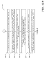
- Figs. 12A and 12B illustrate a non-limiting example of a method 300 of controlling an air conditioning (A/C) compressor in a HVAC system having a thermosiphon evaporator including a mass of phase change material.
- A/C air conditioning
- thermosiphon evaporator that includes a mass of phase change material is provided.
- a variable displacement A/C compressor may be provided.
- a fixed displacement A/C compressor may be provided.
- step 314 MEASURE AN EVAPORATOR OUTPUT AIR TEMPERATURE (EOAT), the temperature of air flowing through the evaporator is measured by a device such as a temperature sensor within the HVAC system.
- EOAT MEASURE AN EVAPORATOR OUTPUT AIR TEMPERATURE
- step 316 GENERATE A STATE OF CHARGE (SoC) VALUE BASED ON THE EOAT, a state of charge value fp is calculated, for example according to the equation above.
- step 318 DETERMINE AN UPPER LIMIT VALUE AND A LOWER LIMIT VALUE FOR THE SoC, an upper limit and a lower limit value for the state of charge value is determined.
- the lower limit may be equal to the value of Mss/(Mss+Ma) where Mss and Ma are as defined above and the upper limit value may be 1 (100%).
- the temperature of the ambient air outside the vehicle cabin may be measured by a temperature sensor.
- the upper limit value of fp may be based on the outside ambient air temperature. When the outside ambient air temperature is low, the upper limit value may be reduced because less cooling of incoming ambient air by the thermosiphon evaporator is required.
- step 322 DETERMINE AN AVERAGE VEHICLE STOP TIME, an average stop time for the vehicle is determined.
- the lower limit value may be based on the average stop time. Shorter stop times may allow the lower limit value to be reduced while longer stop times may require the lower limit value to be increased in order to maintain vehicle cabin comfort during start-stop operation.
- step 324 INITIATE OPERATION OF THE A/C COMPRESSOR WHEN THE VALUE OF THE SoC IS LESS THAN OR EQUAL TO THE LOWER LIMIT VALUE, the A/C compressor is operated when the state of charge value is less than the lower limit in order to change the phase of the of the phase change material from liquid to solid, thereby "charging" the phase change material.
- step 326 OPERATE THE A/C COMPRESSOR IN FULL DISPLACEMENT MODE, if a variable displacement A/C compressor is provided in step 312, the A/C compressor is operated in full displacement mode, thus operating the A/C compressor in a more energy efficient mode than partial displacement mode.
- step 328 DISCONTINUE OPERATION OF THE A/C COMPRESSOR WHEN THE VALUE OF THE SoC IS GREATER THAN OR EQUAL TO THE UPPER LIMIT VALUE, the A/C compressor is shut off by disengaging the A/C compressor from the accessory belt drive or the A/C compressor enters a minimum displacement mode when the state of charge value reaches the upper limit value, signifying that the desired level of charging of the phase change material has been achieved.
- a HVAC system controller may determine whether the HVAC system is operating in a defog or defrost mode.
- step 332 OPERATE THE A/C COMPRESSOR ACCORDING TO A FREEZE CONTROL METHOD WHEN THE HVAC SYSTEM IS OPERATING IN DEFOG MODE, the state of charge control method of steps 312 to 328 may be overridden if it is determined in step 330 that the HVAC system is operating in the defog mode and the A/C compressor will instead be controlled by a freeze control method as described above.
- a humidity value of the air within the vehicle cabin may be determined by a humidity sensor within the vehicle cabin or another method of determining humidity well known to those skilled in the art.
- step 336 OPERATE THE A/C COMPRESSOR ACCORDING TO A FREEZE METHOD WHEN THE HUMIDITY VALUE EXCEEDS A THRESHOLD, the state of charge control method of steps 312 to 328 may be overridden if it is determined in step 334 that the humidity within the cabin exceeds a threshold for comfort of the occupants of the vehicle cabin and the A/C compressor will instead be controlled by a freeze control method as described above.
- the compressor may be used as a brake while generating cooling in the A/C system.
- the transmission is shifted into low gear to achieve high engine speed and with the gasoline supply to the engine cutoff. Compression of air in the cylinder by a high speed engine provides sufficient resistance to the driving wheels to serve as a brake.
- compressor as the brake we propose to operate the engine inlet and exhaust valve timing in such a way that air is continuously inducted and expelled from the cylinder with minimum resistance and with no compression. Thus the rotational energy of the wheel is transmitted to the A/C compressor with high efficiency.
- full stroke or highest possible compressor stroke is used in the case of a variable displacement A/C compressor. This will maximize the cooling generated by the A/C compressor to charge the PCM evaporator. Full stroke operation may cause the evaporator to freeze up the condensate on the air side of the evaporator.
- compressor freeze control needs to be implemented either through appropriately reducing the A/C compressor displacement, or disengaging the clutch of the A/C compressor momentarily, as is well known to those skilled in the art.
- the compressor be allowed to operate so that the evaporator refrigerant temperature is below that normally achieved for standard evaporator condensate freeze control.
- This is referred herein as the sub-freeze compressor control.
- the time period in which the sub-freeze control is allowed may be tracked by a timer and compared to a calibratable time threshold. When the time threshold is exceeded, the A/C compressor can resume normal freeze control, as described above. It is recognized that after the initial sub-freeze control period, depending on the state of charge of the PCM evaporator, sub-freeze compressor control may be periodically used to provide maintenance of the charging state of the PCM material.
- Downhill detection may be achieved by comparing engine power delivery to that recorded on a level road. Power from the engine on a level road is primarily a function of vehicle speed. As the road starts tilting downhill, less power is required to maintain vehicle speed. A critical slope is reached when no power from the engine is needed to maintain the vehicle speed. A steeper downhill grade of the road will cause the vehicle to accelerate. The driver will need start to apply the brake to maintain the vehicle speed. Thus for constant vehicle speed, brake application and zero engine power delivery to the wheel combined can serve as an indication of a significant downhill grade with energy to be recovered. When such a downhill grade is detected, the brake pedal position can be translated into a compressor load by way of A/C compressor control and engine inlet and exhaust valve timing and duration should be adjusted to provide minimum engine resistance.
- Figure 13 illustrates a non-limiting example of method 300 for controlling the compressor to charge the PCM evaporator when the vehicle is driving downhill with energy to recover.
- a similar algorithm may be used when a vehicle decelerates for a traffic stop.
- Traffic stop braking is detected by zero engine power delivery to the wheel, vehicle speed reduction and application of brake pedal.
- the brake pedal position may be translated into a compressor load by controlling the A/C compressor by increasing the A/C compressor displacement, or engaging the clutch of the A/C compressor momentarily.
- the energy stored in the PCM evaporator on a downhill road or during braking may be used to reduce the demand for engine torque from the A/C compressor, thus placing the engine in a more energy efficient operating point in the engine's RPM-torque map, and achieving improved fuel economy.
- Uphill driving may be detected by comparing level road vehicle operation power/torque demand with the current power/torque demand. Under uniform vehicle speed, higher torque and engine speed can serve as an indication that the vehicle is traveling uphill. Another increased power/torque demand occurs when vehicle accelerates from a stop. For either scenario, energy stored by the PCM evaporator helps promote fuel economy by improving the engine operating point on the RPM-torque map per engine efficiency.
- the A/C compressor can be decoupled from the engine or displacement can be minimized to reduce the compressor load on engine.
- the compressor may remain engaged with minimal load to prolong the use of the energy stored in the PCM.
- the compressor load reduction enters the second stage, whereby the A/C compressor will operate according to standard SRR control.
- standard SRR control the A/C compressor begins to work at low load level, and the PCM continues to discharge.
- the engine will perceive reduced load, but not zero load as in the initial period. This can continue for an indefinite period until the PCM is nearly exhausted, as indicated by SoC reaching a lower threshold of calibratable amount of 10%. By this time, either the road hopefully will have leveled off or the vehicle will have accelerated to a desired speed. Otherwise there may no choice but to recharge the PCM to a minimum amount to prepare for stop and go operation.
- the A/C compressor control reverts to PCM compatible SRR control as defined above.
- Figure 14 illustrates a method 400 of controlling the compressor to charge the PCM evaporator when the vehicle is driving uphill.
- a method of recovering braking energy in a vehicle containing a heating ventilation and air conditioning system having the thermosiphon evaporator including the phase change material and a method of controlling an air conditioning compressor in a heating ventilation and air conditioning system having a thermosiphon evaporator including a phase change material is provided.
- the method 200 uses a thermosiphon evaporator with phase change material to store some of the energy received during vehicle braking.
- the method 300 controls an A/C compressor used with a thermosiphon evaporator by monitoring the state of charge value fp. This method provides the benefits of improving energy by allowing a variable displacement A/C compressor to operate primarily in the more energy efficient full displacement mode without freezing the evaporator and reducing the amount of A/C compressor cycling.
- the method 400 controls an A/C compressor used with a thermosiphon evaporator to recover energy from decelerating the vehicle during stopping or maintaining speed on a downhill.
- the method 500 controls an A/C compressor used with a thermosiphon evaporator to decrease the engine load during uphill driving or accelerating from a stop.
Applications Claiming Priority (1)
| Application Number | Priority Date | Filing Date | Title |
|---|---|---|---|
| US13/930,322 US9464837B2 (en) | 2012-03-21 | 2013-06-28 | Phase change material evaporator charging control |
Publications (1)
| Publication Number | Publication Date |
|---|---|
| EP2842778A1 true EP2842778A1 (de) | 2015-03-04 |
Family
ID=50943180
Family Applications (1)
| Application Number | Title | Priority Date | Filing Date |
|---|---|---|---|
| EP14172651.3A Withdrawn EP2842778A1 (de) | 2013-06-28 | 2014-06-17 | Phasenwechselmaterialverdampferladesteuerung |
Country Status (3)
| Country | Link |
|---|---|
| EP (1) | EP2842778A1 (de) |
| KR (1) | KR20150002505A (de) |
| CN (1) | CN104251537B (de) |
Cited By (4)
| Publication number | Priority date | Publication date | Assignee | Title |
|---|---|---|---|---|
| FR3040921A1 (fr) * | 2015-09-15 | 2017-03-17 | Valeo Systemes Thermiques | Procede de regulation d'un systeme de climatisation d'un vehicule automobile |
| FR3040920A1 (fr) * | 2015-09-15 | 2017-03-17 | Valeo Systemes Thermiques | Procede de regulation d'un systeme de climatisation d'un vehicule automobile |
| US11542147B2 (en) | 2019-09-30 | 2023-01-03 | Marmon Foodservice Technologies, Inc. | Beverage dispensers with heat exchangers |
| US20230302875A1 (en) * | 2022-03-23 | 2023-09-28 | Mahle International Gmbh | Heat storage heat pump heater |
Families Citing this family (4)
| Publication number | Priority date | Publication date | Assignee | Title |
|---|---|---|---|---|
| US20180340740A1 (en) * | 2015-03-26 | 2018-11-29 | Borgwarner Inc. | Use of a phase change material system |
| CN107839435A (zh) * | 2017-11-14 | 2018-03-27 | 西南计算机有限责任公司 | 一种基于相变材料的车辆智能温控系统 |
| US10806022B2 (en) * | 2018-08-09 | 2020-10-13 | Hanon Systems | Fluid heating heater |
| NL2023924B1 (nl) * | 2019-10-01 | 2021-06-01 | Lely Patent Nv | Meetsysteem voor levensmiddelen |
Citations (5)
| Publication number | Priority date | Publication date | Assignee | Title |
|---|---|---|---|---|
| DE10317521A1 (de) * | 2002-04-19 | 2003-10-30 | Denso Corp | Fahrzeugklimasystem mit Kältespeichereinheit |
| WO2004035335A1 (de) * | 2002-10-10 | 2004-04-29 | Behr Gmbh & Co. | Verfahren zur verdampfungstemperaturregelung bei einer klimaanlage |
| US20090266094A1 (en) * | 2008-04-23 | 2009-10-29 | Gm Global Technology Operations, Inc. | Air Conditioning System with Cold Thermal Storage and Evaporator Temperature Control |
| US20110067419A1 (en) * | 2009-09-24 | 2011-03-24 | Denso Corporaiton | Air-conditioning control device for vehicle |
| US8397529B2 (en) | 2009-06-10 | 2013-03-19 | Delphi Technologies, Inc. | Evaporator phase change thermal siphon |
Family Cites Families (2)
| Publication number | Priority date | Publication date | Assignee | Title |
|---|---|---|---|---|
| CN2538581Y (zh) * | 2002-03-07 | 2003-03-05 | 广东工业大学 | 汽车蓄冷空调装置 |
| CN102767874A (zh) * | 2011-05-05 | 2012-11-07 | 东风贝洱热系统有限公司 | 蓄冷式汽车空调系统 |
-
2014
- 2014-06-17 EP EP14172651.3A patent/EP2842778A1/de not_active Withdrawn
- 2014-06-25 KR KR20140078226A patent/KR20150002505A/ko not_active Application Discontinuation
- 2014-06-27 CN CN201410301110.1A patent/CN104251537B/zh not_active Expired - Fee Related
Patent Citations (5)
| Publication number | Priority date | Publication date | Assignee | Title |
|---|---|---|---|---|
| DE10317521A1 (de) * | 2002-04-19 | 2003-10-30 | Denso Corp | Fahrzeugklimasystem mit Kältespeichereinheit |
| WO2004035335A1 (de) * | 2002-10-10 | 2004-04-29 | Behr Gmbh & Co. | Verfahren zur verdampfungstemperaturregelung bei einer klimaanlage |
| US20090266094A1 (en) * | 2008-04-23 | 2009-10-29 | Gm Global Technology Operations, Inc. | Air Conditioning System with Cold Thermal Storage and Evaporator Temperature Control |
| US8397529B2 (en) | 2009-06-10 | 2013-03-19 | Delphi Technologies, Inc. | Evaporator phase change thermal siphon |
| US20110067419A1 (en) * | 2009-09-24 | 2011-03-24 | Denso Corporaiton | Air-conditioning control device for vehicle |
Cited By (4)
| Publication number | Priority date | Publication date | Assignee | Title |
|---|---|---|---|---|
| FR3040921A1 (fr) * | 2015-09-15 | 2017-03-17 | Valeo Systemes Thermiques | Procede de regulation d'un systeme de climatisation d'un vehicule automobile |
| FR3040920A1 (fr) * | 2015-09-15 | 2017-03-17 | Valeo Systemes Thermiques | Procede de regulation d'un systeme de climatisation d'un vehicule automobile |
| US11542147B2 (en) | 2019-09-30 | 2023-01-03 | Marmon Foodservice Technologies, Inc. | Beverage dispensers with heat exchangers |
| US20230302875A1 (en) * | 2022-03-23 | 2023-09-28 | Mahle International Gmbh | Heat storage heat pump heater |
Also Published As
| Publication number | Publication date |
|---|---|
| KR20150002505A (ko) | 2015-01-07 |
| CN104251537B (zh) | 2019-03-08 |
| CN104251537A (zh) | 2014-12-31 |
Similar Documents
| Publication | Publication Date | Title |
|---|---|---|
| US9464837B2 (en) | Phase change material evaporator charging control | |
| EP2842778A1 (de) | Phasenwechselmaterialverdampferladesteuerung | |
| US9400510B2 (en) | Phase change material evaporator charging control | |
| US10220828B2 (en) | Engine idle operation control method and system for heating of hybrid electric vehicle | |
| US9337680B2 (en) | Method and system for controlling an electric vehicle while charging | |
| CN106143062B (zh) | 给热泵去冰的系统和方法 | |
| CN105322249B (zh) | 确定电气化车辆的电池热管理系统中的冷却剂泵的运行状态的方法 | |
| EP0640503B1 (de) | Elektrisches fahrzeug | |
| US9090262B2 (en) | Control apparatus for vehicle | |
| US10696290B2 (en) | Hybrid vehicle and powertrain | |
| US11465533B2 (en) | Acceleration control system for an electric vehicle | |
| US20170368911A1 (en) | Vehicle air-conditioning control device | |
| CA2888029A1 (en) | Power generation control device | |
| JP3745677B2 (ja) | 車両用回生制動装置 | |
| JP2007015524A (ja) | 車両制御装置 | |
| US10596877B2 (en) | Air conditioning device for vehicle | |
| KR100867824B1 (ko) | 하이브리드 차량의 제어방법 | |
| US20180312038A1 (en) | Air conditioner for vehicle | |
| CN111660762A (zh) | 车辆热泵系统中的除冰控制 | |
| US11511728B2 (en) | Control unit for controlling traveling state and air conditioning state | |
| JP4765716B2 (ja) | 熱エネルギ利用装置 | |
| KR20190049144A (ko) | 하이브리드 자동차 및 그를 위한 공조 제어 방법 | |
| EP4101683A1 (de) | Leistungssystem zur versorgung eines kühlschranks eines kühlfahrzeugs mit elektrischer energie und zugehöriges steuersystem und verfahren | |
| JP6032192B2 (ja) | ハイブリッド車の制御装置 | |
| US20200247211A1 (en) | Motor vehicle including a climate control system with accumulator, and corresponding method |
Legal Events
| Date | Code | Title | Description |
|---|---|---|---|
| 17P | Request for examination filed |
Effective date: 20140617 |
|
| AK | Designated contracting states |
Kind code of ref document: A1 Designated state(s): AL AT BE BG CH CY CZ DE DK EE ES FI FR GB GR HR HU IE IS IT LI LT LU LV MC MK MT NL NO PL PT RO RS SE SI SK SM TR |
|
| AX | Request for extension of the european patent |
Extension state: BA ME |
|
| PUAI | Public reference made under article 153(3) epc to a published international application that has entered the european phase |
Free format text: ORIGINAL CODE: 0009012 |
|
| R17P | Request for examination filed (corrected) |
Effective date: 20150902 |
|
| RBV | Designated contracting states (corrected) |
Designated state(s): AL AT BE BG CH CY CZ DE DK EE ES FI FR GB GR HR HU IE IS IT LI LT LU LV MC MK MT NL NO PL PT RO RS SE SI SK SM TR |
|
| RAP1 | Party data changed (applicant data changed or rights of an application transferred) |
Owner name: MAHLE INTERNATIONAL GMBH |
|
| 17Q | First examination report despatched |
Effective date: 20170914 |
|
| GRAP | Despatch of communication of intention to grant a patent |
Free format text: ORIGINAL CODE: EPIDOSNIGR1 |
|
| INTG | Intention to grant announced |
Effective date: 20200128 |
|
| STAA | Information on the status of an ep patent application or granted ep patent |
Free format text: STATUS: THE APPLICATION IS DEEMED TO BE WITHDRAWN |
|
| 18D | Application deemed to be withdrawn |
Effective date: 20200609 |