EP3061635A1 - Hlk-system zur fahrreichweitenerweiterung eines elektrofahrzeugs - Google Patents
Hlk-system zur fahrreichweitenerweiterung eines elektrofahrzeugs Download PDFInfo
- Publication number
- EP3061635A1 EP3061635A1 EP16157243.3A EP16157243A EP3061635A1 EP 3061635 A1 EP3061635 A1 EP 3061635A1 EP 16157243 A EP16157243 A EP 16157243A EP 3061635 A1 EP3061635 A1 EP 3061635A1
- Authority
- EP
- European Patent Office
- Prior art keywords
- heat exchanger
- cooling
- mode
- heating
- range extending
- Prior art date
- Legal status (The legal status is an assumption and is not a legal conclusion. Google has not performed a legal analysis and makes no representation as to the accuracy of the status listed.)
- Granted
Links
Images


Classifications
-
- B—PERFORMING OPERATIONS; TRANSPORTING
- B60—VEHICLES IN GENERAL
- B60H—ARRANGEMENTS OF HEATING, COOLING, VENTILATING OR OTHER AIR-TREATING DEVICES SPECIALLY ADAPTED FOR PASSENGER OR GOODS SPACES OF VEHICLES
- B60H1/00—Heating, cooling or ventilating [HVAC] devices
- B60H1/00492—Heating, cooling or ventilating [HVAC] devices comprising regenerative heating or cooling means, e.g. heat accumulators
-
- B—PERFORMING OPERATIONS; TRANSPORTING
- B60—VEHICLES IN GENERAL
- B60H—ARRANGEMENTS OF HEATING, COOLING, VENTILATING OR OTHER AIR-TREATING DEVICES SPECIALLY ADAPTED FOR PASSENGER OR GOODS SPACES OF VEHICLES
- B60H1/00—Heating, cooling or ventilating [HVAC] devices
- B60H1/00357—Air-conditioning arrangements specially adapted for particular vehicles
- B60H1/00385—Air-conditioning arrangements specially adapted for particular vehicles for vehicles having an electrical drive, e.g. hybrid or fuel cell
-
- B—PERFORMING OPERATIONS; TRANSPORTING
- B60—VEHICLES IN GENERAL
- B60H—ARRANGEMENTS OF HEATING, COOLING, VENTILATING OR OTHER AIR-TREATING DEVICES SPECIALLY ADAPTED FOR PASSENGER OR GOODS SPACES OF VEHICLES
- B60H1/00—Heating, cooling or ventilating [HVAC] devices
- B60H1/00642—Control systems or circuits; Control members or indication devices for heating, cooling or ventilating devices
- B60H1/00735—Control systems or circuits characterised by their input, i.e. by the detection, measurement or calculation of particular conditions, e.g. signal treatment, dynamic models
- B60H1/00764—Control systems or circuits characterised by their input, i.e. by the detection, measurement or calculation of particular conditions, e.g. signal treatment, dynamic models the input being a vehicle driving condition, e.g. speed
- B60H1/00778—Control systems or circuits characterised by their input, i.e. by the detection, measurement or calculation of particular conditions, e.g. signal treatment, dynamic models the input being a vehicle driving condition, e.g. speed the input being a stationary vehicle position, e.g. parking or stopping
-
- B—PERFORMING OPERATIONS; TRANSPORTING
- B60—VEHICLES IN GENERAL
- B60H—ARRANGEMENTS OF HEATING, COOLING, VENTILATING OR OTHER AIR-TREATING DEVICES SPECIALLY ADAPTED FOR PASSENGER OR GOODS SPACES OF VEHICLES
- B60H1/00—Heating, cooling or ventilating [HVAC] devices
- B60H1/00642—Control systems or circuits; Control members or indication devices for heating, cooling or ventilating devices
- B60H1/00814—Control systems or circuits characterised by their output, for controlling particular components of the heating, cooling or ventilating installation
- B60H1/00878—Control systems or circuits characterised by their output, for controlling particular components of the heating, cooling or ventilating installation the components being temperature regulating devices
- B60H1/00899—Controlling the flow of liquid in a heat pump system
- B60H1/00907—Controlling the flow of liquid in a heat pump system where the flow direction of the refrigerant changes and an evaporator becomes condenser
-
- B—PERFORMING OPERATIONS; TRANSPORTING
- B60—VEHICLES IN GENERAL
- B60H—ARRANGEMENTS OF HEATING, COOLING, VENTILATING OR OTHER AIR-TREATING DEVICES SPECIALLY ADAPTED FOR PASSENGER OR GOODS SPACES OF VEHICLES
- B60H1/00—Heating, cooling or ventilating [HVAC] devices
- B60H1/02—Heating, cooling or ventilating [HVAC] devices the heat being derived from the propulsion plant
- B60H1/14—Heating, cooling or ventilating [HVAC] devices the heat being derived from the propulsion plant otherwise than from cooling liquid of the plant, e.g. heat from the grease oil, the brakes, the transmission unit
- B60H1/143—Heating, cooling or ventilating [HVAC] devices the heat being derived from the propulsion plant otherwise than from cooling liquid of the plant, e.g. heat from the grease oil, the brakes, the transmission unit the heat being derived from cooling an electric component, e.g. electric motors, electric circuits, fuel cells or batteries
-
- B—PERFORMING OPERATIONS; TRANSPORTING
- B60—VEHICLES IN GENERAL
- B60H—ARRANGEMENTS OF HEATING, COOLING, VENTILATING OR OTHER AIR-TREATING DEVICES SPECIALLY ADAPTED FOR PASSENGER OR GOODS SPACES OF VEHICLES
- B60H1/00—Heating, cooling or ventilating [HVAC] devices
- B60H1/00007—Combined heating, ventilating, or cooling devices
- B60H1/00021—Air flow details of HVAC devices
- B60H2001/0015—Temperature regulation
- B60H2001/00178—Temperature regulation comprising an air passage from the HVAC box to the exterior of the cabin
-
- B—PERFORMING OPERATIONS; TRANSPORTING
- B60—VEHICLES IN GENERAL
- B60H—ARRANGEMENTS OF HEATING, COOLING, VENTILATING OR OTHER AIR-TREATING DEVICES SPECIALLY ADAPTED FOR PASSENGER OR GOODS SPACES OF VEHICLES
- B60H1/00—Heating, cooling or ventilating [HVAC] devices
- B60H1/00642—Control systems or circuits; Control members or indication devices for heating, cooling or ventilating devices
- B60H1/00814—Control systems or circuits characterised by their output, for controlling particular components of the heating, cooling or ventilating installation
- B60H1/00878—Control systems or circuits characterised by their output, for controlling particular components of the heating, cooling or ventilating installation the components being temperature regulating devices
- B60H2001/00949—Control systems or circuits characterised by their output, for controlling particular components of the heating, cooling or ventilating installation the components being temperature regulating devices comprising additional heating/cooling sources, e.g. second evaporator
Definitions
- HVAC system heating, ventilation, and air conditioning
- Heating and cooling systems for a plug in type electric vehicle typically use a vapor compression type heating and cooling system (heat pump) with an electrically driven compressor. This represents a significant electrical load on the system that can shorten the driving range, especially during extremes of ambient temperature, hot or cold.
- PCM phase change material
- thermoelectric device to provide the heating or cooling of the PCM reservoir while the vehicle is plugged in, while simultaneously opening a selective inlet and outlet path to the ambient air for the air necessary for operation of the thermoelectric device.
- the heat battery is used in a conventional, direct conduction or convection manner. That is, hot air from the cabin is blown directly over it to be cooled in the summer, or cold cabin air blown over it to be heated in the winter.
- a different PCM material with a melt temperature comparable to the very different heating comfort level temperature in the winter, or to the cooling comfort level temperature in the summer would have to be used, and swapped out as the seasons changed. This is an inconvenience that a vehicle owner would be unlikely to tolerate.
- PCM reservoir has a melt temperature near, or just below, the cooling mode target temperature, and it is cooled by the "extra" compressor power available when the compressor is operating as the internal combustion engine is operating. Cabin air, in turn, is cooled by forced flow directly across a heat exchanger that carries a coolant cooled within the PCM reservoir to that temperature. In heating mode, extra heat from the internal combustion engine cooling system is used to elevate the temperature of what will already be likely melted PCM material in the reservoir.
- an additional heating circuit can be switched in to draw heat by direct conduction or convection out of the previously heated PCM reservoir.
- an extra heat transfer circuit is provided, with an additional compressor and heat pump componentry, to draw additional heat indirectly out of the PCM reservoir when it has grown too cold to be used directly.
- the subject application provides a system for extending the range of a plug in type electrical vehicle of the type having an electrically driven heat pump type, vapor compression heating and cooling system, including an exterior heat exchanger capable of acting as either a condenser or an evaporator, and an interior, cabin heat exchanger capable of acting as either an evaporator or condenser in conjunction with the mode of the exterior heat exchanger.
- a heat exchanger is dedicated as a condenser or evaporator full time.
- the system can operate in normal, primary heat pump mode, drawing heat from, or dumping it to, the ambient air as the vehicle operates.
- a range extending means is provided to initially supplement the ordinary, heat pump heating and cooling action.
- a duct arrangement is adapted to selectively establish a temporary flow path between the cabin heat exchanger and the ambient air during the battery charging period.
- the compressor is run during the charging period, from the same electrical source that is charging the batteries, and a switching valve takes the outdoor heat exchanger out of the loop.
- a reversing valve assures that the compressor circulates the refrigerant in a direction that either allows the cabin heat exchanger to act as a condenser, upstream of an expansion valve, or as an evaporator, downstream of the expansion valve.
- the refrigerant dumps heat to the ambient air, and when acting as an evaporator, it absorbs heat from the ambient air.
- the system also includes a single energy storage heat exchanger assembly surrounded by a reservoir of phase change material having a phase change temperature between or around targeted comfort mode temperatures of the vehicle cabin, with a heating comfort mode temperature being generally slightly lower than a cooling comfort mode temperature.
- the phase change meterial is of the solid-liquid type, in which heat is absorbed by the material through the phase transition from the solid state to the liquid state, while maintaining a generally constant temperature around the phase change temperature during the phase change until all of the material is melted. Conversely, heat is released by the material during the reverse phase change from the liquid state to the solid state while again maintaining a generally constant temperature during the phase change around the phase change temperature.
- This energy storage or reservoir heat exchanger is plumbed in parallel to the exterior heat exchanger, and a switching valve selectively takes the exterior heater exchanger out of the system and puts the energy storage heat exchanger in series with said cabin heat exchanger. This is done during the charging mode, in order to allow the "storage" of cold during hot months, and the storage of heat in the cold months.
- the switching valve also keeps the energy storage heat exchanger in series with the cabin heat exchanger, and the exterior heat exchanger off line, temporarily as the vehicle begins operating to establish a secondary, range extending heating cooling mode.
- the phase change material stores much more heat or "cold,” per unit of volume, than the ambient air, and until that store is depleted, the compressor can operate with far less energy than it can during conventional heat pump operation.
- the switching valve simply disconnects the energy storage heat exchanger and puts the conventional exterior heat exchanger back on line, to allow operation in the less efficient, conventional heat pump mode, with ambient air serving as the heat source (heating mode) or heat sink (cooling mode).
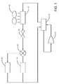
- the range extending system of the invention includes all the elements of a standard heat pump system, typical in an electric vehicle with an electric compressor 10.
- An exterior heat exchanger 14 which would always be the condenser in a conventional air conditioning system, and an interior or cabin air heat exchanger 12, which would always be the evaporator in a conventional air conditioning system.
- Exterior heat exchanger 14 is shown in phantom lines, as it is always off line during the novel processes described below.
- the inner and outer heat exchangers 12 and 14 switch tasks, acting as condenser or evaporator alternately, depending on whether cooling or heating is needed.
- cabin heat exchanger 12 acts as the evaporator
- exterior heat exchanger 14 as the condenser.
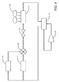
- Compressor 10 would send compressed and heated refrigerant through a reversing valve 16 and toward the exterior heat exchanger/condenser 14 (as shown in Figure 3 , counterflow to the direction shown in Figure 1 ).
- the compressed and hot refrigerant would dump heat to the ambient air, and then flow to through an expansion valve 18 (here routed through a switching valve 20, which would not be present in a conventional heat pump system).
- the standard heat pump system acts like, and essentially as efficiently as, a conventional air conditioning system.
- the inherent inefficiency of the standard heat pump system resides in its heating mode.
- the heating mode of the standard heat pump system (as generally shown in Fig. 6 , except that valve 20 and heat exchanger assembly 24 would be absent)
- the refrigerant flow path just described would be reversed by the reversing valve 16 and hot and compressed refrigerant would be run through cabin air heat exchanger 12, dumping what would have been waste heat in a cooling cycle to the cabin.
- the condensed refrigerant would run through expansion valve 18, expanded and cooled, and ultimately run through the exterior heat exchanger 14 which would now act as an evaporator to further cool, and pick up any available heat from, the already cold ambient air.
- the refrigerant would then be fed back to the compressor 10 and ultimately to the indoor heat exchanger 12 acting as condenser/interior heater again.
- the present application provides an at least temporary alternative to using just the ambient air as a heat source and heat sink, thereby extending the range of the vehicle.
- a duct arrangement 22 is provided to selectively establish a temporary flow path between the cabin heat exchanger 12 and the ambient air. This is done during the battery charging period, typically at night, with suitable automatically acting doors and vents in the duct arrangement 22.
- the compressor 10 is run during this charging period, from the same electrical source that is charging the batteries, and hot and compressed refrigerant is run through cabin heat exchanger 12, acting as a condenser, which dumps heat to the ambient air by virtue of the path provided by the duct arrangement 22. Refrigerant then flows from cabin heat exchanger/condenser 12 though expansion valve 18, where it is rapidly expanded and cooled.
- switching valve 20 which has removed the outdoor heat exchanger 14 from the loop, instead routes the refrigerant from trough a phase changer material (PCM) heat exchanger assembly 24, which would comprise a heat exchanger like a coil surrounded and in intimate contact with a phase change material.
- PCM phase changer material
- Cold refrigerant is run through, and picks up heat from, the heat exchanger assembly, and then is run back through compressor 10 and into the cycle anew.
- the PCM heat exchanger cools the refrigerant.
- the switching valve may be a two-position solenoid valve with a normal, unpowered state and an energized state.
- the normal state connects the expansion valve 18 with the exterior heat exchanger 14. This has the advantage that, if the switching valve solenoid drive fails, a regular HVAC system is still available, albeit without the added benefit of the PCM heat exchanger 24.
- This heat-removing charging operation may continue until some defined parameter is met, such as a target cold temperature of the phase changer material PCM heat exchanger 24.
- the PCM heat exchanger assembly 24 may be cycled periodically as needed to maintain the condition of meeting the defined parameter.
- the phase change material can deliberately be given a melt/phase change temperature that lies between the desired heating or cooling comfort temperatures of the vehicle, and so would be unsuitable for direct conduction cooling or heating of the cabin air, in the way that phase change reservoirs are typically used. However, it is a single material that does not require a swap or change between heating and cooling seasons because it is utilized in a different manner than typical coolants (described next). Again, compressor 10 is being run during this charging period by the external current source, not the vehicle batteries. While there is no such thing as a loss-free operation in any thermodynamic system, this method of cold charging during a recharging operation of the vehicle is at least energy provided by a virtually unlimited external source that does not drain the vehicle battery.
- the duct arrangement 22 shuts off the temporary path to ambient air, but the switching valve 20 continues to keep the energy storage heat exchanger 24 plumbed in series with the cabin heat exchanger 12, while concurrently keeping the exterior heat exchanger 14 off line.
- the reversing valve 16 reverses the flow of refrigerant from its cold charging flow path, and hot and compressed refrigerant passes through PCM heat exchanger 24, to which transfers heat, instead of to the ambient air.
- PCM heat exchanger 24 will have a temperature lower than the ambient air, this provides a much more efficient heat sink.
- Cooled and compressed refrigerant then runs through the expansion valve 18, where it is expanded and cooled, and ultimately through the cabin air heat exchanger 12, acting as an evaporator to cool the cabin air.
- This establishes a range extending mode, different from, and more efficient than, the standard heat pump mode, which uses the ambient air as the heat sink.
- This range extending mode continues until the PCM heat exchanger and reservoir 24 is sufficiently heated (“cold depleted") that it is no longer more efficient than the ambient air acting as a heat source.
- the switching valve 20 puts the exterior heat exchanger 14 (now condenser) back on line and the PCM exchanger 24 off line, as seen in Figure 3 , to return to the standard, albeit less efficient, heat pump cooling mode. Because of this externally charged thermodynamic cooling capacity, the driving range of the vehicle has been accordingly extended.
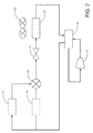
- a heating season charging mode is illustrated and can be described more briefly.
- the reversing valve 16 reverses the refrigerant flow path shown in Figure 1 .
- Duct arrangement 22 is opened during the charging period to allow cabin air heat exchanger 12 to serve as an evaporator.
- the refrigerant passes through switching valve 20, expansion valve 18, and through cabin air heat exchanger/evaporator 12 (where it absorbs what heat is available from the ambient air), and back to the compressor 10.
- reversing valve 16 reverses the flow of refrigerant from the Figure 4 charging mode, and cabin air heat exchanger 12 acts as a condenser, while the duct arrangement 22 shuts off the temporary path to ambient air.
- Hot and compressed refrigerant from compressor 10 passes through cabin air heat exchanger 12, releasing heat to the vehicle interior, then through expansion valve 18, where it is expanded and rapidly cooled, then through PCM heat exchanger 24, where it is warmed, before returning to compressor 10.
- the duct arrangement 22 only supplies ambient air to the cabin heat exchanger 12 when the switching valve 20 is set to provide a refrigerant path through the PCM heat exchanger 24.
- the switching valve 20 also establishes the refrigerant path through the PCM heat exchanger 24 during the range extending cooling and heating operations so that the states of operation of the duct arrangement and of the switching valve are not tied to each other.
- the following table provides the different settings of Figs.
- Mode Reversing Valve 16 directs compressed refrigerant Switching Valve 20 connects Duct Arrangement 22, supply of ambient air is cooling charging mode to cabin heat exchanger PCM heat exchanger open range extending cooling operation away from cabin heat exchanger PCM heat exchanger closed standard cooling operation away from cabin heat exchanger exterior heat exchanger closed heating charging mode away from cabin heat exchanger PCM heat exchanger open range extending heating operation to cabin heat exchanger PCM heat exchanger closed standard heating operation to cabin heat exchanger exterior heat exchanger closed
- the heating or cooling charging mode may be selected prior to charging the vehicle battery.
- the selection may be made by manual control, preferably with an additional "none" option when outside temperatures are moderate and no cabin temperature control appears to be necessary in the near future.
- an electronic controller may apply selection criteria based on ambient air temperature in comparison with comfort mode temperatures or based a recorded recent heating/cooling history of the system.
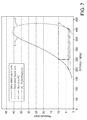
- Figure 7 shows the familiar Pressure-Enthalpy curve of a vapor compression heat pump.
- the vapor line (dashed) and liquid line (solid) of the curve are labeled V and L, and the operational line of the conventional heat pump AC system is shown as the much higher and steeper of the two lines shown as a dash-dotted line.
- the system operational line during operation with the reservoir assisted system of the invention is the much shorter of the two lines shown as dash-double-dotted line. This much lower "lift” is visually indicative of the much higher COP available during the temporary, reservoir assisted heating or cooling modes.
Applications Claiming Priority (1)
| Application Number | Priority Date | Filing Date | Title |
|---|---|---|---|
| US201562121745P | 2015-02-27 | 2015-02-27 |
Publications (2)
| Publication Number | Publication Date |
|---|---|
| EP3061635A1 true EP3061635A1 (de) | 2016-08-31 |
| EP3061635B1 EP3061635B1 (de) | 2017-08-16 |
Family
ID=55521458
Family Applications (1)
| Application Number | Title | Priority Date | Filing Date |
|---|---|---|---|
| EP16157243.3A Active EP3061635B1 (de) | 2015-02-27 | 2016-02-25 | Hlk-system zur fahrreichweitenerweiterung eines elektrofahrzeugs |
Country Status (3)
| Country | Link |
|---|---|
| US (1) | US9809083B2 (de) |
| EP (1) | EP3061635B1 (de) |
| CN (1) | CN105922839B (de) |
Cited By (3)
| Publication number | Priority date | Publication date | Assignee | Title |
|---|---|---|---|---|
| CN107867143A (zh) * | 2016-09-27 | 2018-04-03 | 翰昂汽车零部件有限公司 | 将热能传递至分配向车辆客舱的空气的方法 |
| WO2019162680A1 (en) * | 2018-02-21 | 2019-08-29 | The University Of Birmingham | Vehicle charging |
| DE102020108015A1 (de) | 2020-03-24 | 2021-09-30 | Audi Aktiengesellschaft | Kraftfahrzeug mit einem elektrischen Fahrantrieb und mit einer Klimatisierungseinrichtung |
Families Citing this family (5)
| Publication number | Priority date | Publication date | Assignee | Title |
|---|---|---|---|---|
| US10436495B2 (en) * | 2015-05-01 | 2019-10-08 | Thermo King Corporation | Integrated thermal energy module within an air-cooled evaporator design |
| US9975400B2 (en) * | 2015-06-18 | 2018-05-22 | Ford Global Technologies, Llc | Method of controlling climate in a parked vehicle |
| JP7226089B2 (ja) * | 2019-05-21 | 2023-02-21 | 株式会社デンソー | 車両用空調装置 |
| US11597255B2 (en) * | 2020-03-25 | 2023-03-07 | Pony Al Inc. | Systems and methods for cooling vehicle components |
| CN112611010B (zh) * | 2020-11-30 | 2022-06-28 | 华北电力大学 | 一种多热源热电联产机组发电负荷灵活调节系统的调节方法 |
Citations (4)
| Publication number | Priority date | Publication date | Assignee | Title |
|---|---|---|---|---|
| EP0640503A1 (de) * | 1993-03-22 | 1995-03-01 | Seiko Epson Corporation | Elektrisches fahrzeug |
| EP1533154A1 (de) * | 2002-07-16 | 2005-05-25 | Toyota Jidosha Kabushiki Kaisha | Klimaanlage |
| US20120152511A1 (en) | 2010-12-15 | 2012-06-21 | Sunny General International Co., Ltd. | Lhtes device for electric vehicle, system comprising the same and method for controlling the same |
| WO2013088190A1 (en) | 2011-12-14 | 2013-06-20 | Renault Trucks | Thermal control system for a cabin of a vehicle and method for controlling the cabin temperature |
Family Cites Families (81)
| Publication number | Priority date | Publication date | Assignee | Title |
|---|---|---|---|---|
| US3175953A (en) * | 1962-02-27 | 1965-03-30 | Nettel Frederick | Steam-cooled nuclear reactor power plant |
| US4063546A (en) * | 1975-04-28 | 1977-12-20 | Ciba-Geigy Corporation | Heat store and installation for the utilization of solar energy |
| US4041705A (en) * | 1976-04-07 | 1977-08-16 | Israel Siegel | Low temperature engine |
| GB1584872A (en) * | 1976-07-09 | 1981-02-18 | Laing Nikolaus | Heating circuits supplied from district heating grids |
| US4127161A (en) * | 1977-03-02 | 1978-11-28 | Energy Recycling Company | Energy storage unit and system |
| US4286141A (en) * | 1978-06-22 | 1981-08-25 | Calmac Manufacturing Corporation | Thermal storage method and system utilizing an anhydrous sodium sulfate pebble bed providing high-temperature capability |
| US4403645A (en) * | 1978-07-12 | 1983-09-13 | Calmac Manufacturing Corporation | Compact storage of seat and coolness by phase change materials while preventing stratification |
| US4265223A (en) * | 1978-09-18 | 1981-05-05 | The Badger Company, Inc. | Method and apparatus for utilizing solar energy |
| US4248291A (en) * | 1978-10-18 | 1981-02-03 | Seymour Jarmul | Compact thermal energy reservoirs |
| DK26179A (da) * | 1979-01-22 | 1980-07-23 | Eftex Innovation A S | Varmelager |
| US4402188A (en) * | 1979-07-11 | 1983-09-06 | Skala Stephen F | Nested thermal reservoirs with heat pumping therebetween |
| JPS56160208A (en) * | 1980-05-13 | 1981-12-09 | Nissan Motor Co Ltd | Spot heater for vehicle |
| US4491172A (en) * | 1981-04-22 | 1985-01-01 | Thermal Energy Storage, Inc. | Energy storage apparatus |
| US4696338A (en) * | 1982-06-01 | 1987-09-29 | Thermal Energy Stroage, Inc. | Latent heat storage and transfer system and method |
| US4403644A (en) * | 1982-09-20 | 1983-09-13 | Hebert Raymond T | Method and apparatus for room temperature stabilization |
| US4940079A (en) * | 1988-08-11 | 1990-07-10 | Phenix Heat Pump Systems, Inc. | Optimal control system for refrigeration-coupled thermal energy storage |
| US5553662A (en) * | 1993-12-10 | 1996-09-10 | Store Heat & Producte Energy, Inc. | Plumbed thermal energy storage system |
| US5944089A (en) * | 1994-05-26 | 1999-08-31 | Roland; Russel Anthony | Thermal storage systems for buildings |
| US5442931A (en) * | 1994-08-02 | 1995-08-22 | Gas Research Institute | Simplified adsorption heat pump using passive heat recuperation |
| US6059016A (en) * | 1994-08-11 | 2000-05-09 | Store Heat And Produce Energy, Inc. | Thermal energy storage and delivery system |
| DE4441352C2 (de) * | 1994-11-21 | 1999-02-25 | Bayerische Motoren Werke Ag | Fahrzeugheizung |
| US5579830A (en) * | 1995-11-28 | 1996-12-03 | Hudson Products Corporation | Passive cooling of enclosures using heat pipes |
| US6063525A (en) * | 1997-11-20 | 2000-05-16 | Bipolar Technologies Corp. | Source of electrical power for an electric vehicle and other purposes, and related methods |
| US6170263B1 (en) * | 1999-05-13 | 2001-01-09 | General Electric Co. | Method and apparatus for converting low grade heat to cooling load in an integrated gasification system |
| US6393861B1 (en) * | 1999-09-17 | 2002-05-28 | Robert Levenduski | Thermal storage apparatus and method for air conditioning system |
| US6624349B1 (en) * | 2000-11-08 | 2003-09-23 | Hi-Z Technology, Inc. | Heat of fusion phase change generator |
| CN100353134C (zh) * | 2001-09-25 | 2007-12-05 | 本田技研工业株式会社 | 蓄热装置及其制造方法 |
| US9113577B2 (en) * | 2001-11-27 | 2015-08-18 | Thermotek, Inc. | Method and system for automotive battery cooling |
| DE10321646A1 (de) * | 2002-06-03 | 2004-07-15 | Rubitherm Gmbh | Verfahren zur Wärme- und Kälteversorgung eines Raumes und Gebäude mit einer Mehrzahl mit einer Mehrzahl von Räumen |
| US6631755B1 (en) * | 2002-07-17 | 2003-10-14 | Compal Electronics, Inc. | Thermal module with temporary heat storage |
| EP1471324A3 (de) * | 2003-04-22 | 2005-11-16 | Matsushita Electric Industrial Co., Ltd. | Wärmespeicheranlage und Wärmespeicherverfahren |
| DE102004019607A1 (de) * | 2004-04-22 | 2006-01-12 | Webasto Ag | Heiz- und Klimatisierungssystem für ein Kraftfahrzeug |
| JP4805265B2 (ja) * | 2004-08-06 | 2011-11-02 | エルジー・ケム・リミテッド | 内部構造に相変化材料含有カプセルを含むバッテリーシステム |
| US20060266043A1 (en) * | 2004-09-28 | 2006-11-30 | Allan Jerome | Power generation system |
| US7882888B1 (en) * | 2005-02-23 | 2011-02-08 | Swales & Associates, Inc. | Two-phase heat transfer system including a thermal capacitance device |
| US7464672B2 (en) * | 2007-03-07 | 2008-12-16 | Aqwest, Llc | Engine cooling system with overload handling capability |
| US9222371B2 (en) * | 2007-06-08 | 2015-12-29 | Stephen J. Farkaly | Efficient heat exchange system for storing energy |
| US8049460B2 (en) * | 2007-07-18 | 2011-11-01 | Tesla Motors, Inc. | Voltage dividing vehicle heater system and method |
| US8272432B2 (en) * | 2007-11-28 | 2012-09-25 | GM Global Technology Operations LLC | HVAC thermal storage for hybrid vehicle |
| US8584734B2 (en) * | 2008-02-11 | 2013-11-19 | Navatek, Ltd | Two material phase change energy storage system |
| US8302417B2 (en) * | 2008-04-23 | 2012-11-06 | GM Global Technology Operations LLC | Air conditioning system with cold thermal storage and evaporator temperature control |
| GB0808930D0 (en) * | 2008-05-16 | 2008-06-25 | Sunamp Ltd | Energy Storage system |
| US8631855B2 (en) * | 2008-08-15 | 2014-01-21 | Lighting Science Group Corporation | System for dissipating heat energy |
| US8887843B2 (en) * | 2008-10-02 | 2014-11-18 | Ford Global Technologies, Llc | Hybrid electric vehicle and method for managing heat therein |
| US8651704B1 (en) * | 2008-12-05 | 2014-02-18 | Musco Corporation | Solid state light fixture with cooling system with heat rejection management |
| FR2943775B1 (fr) * | 2009-03-24 | 2012-07-13 | Valeo Systemes Thermiques | Echangeur de stockage pourvu d'un materiau stockeur et boucle de climatisation ou circuit de refroidissement comprenant un tel echangeur. |
| CN102460024B (zh) * | 2009-06-16 | 2014-12-10 | Dec设计机械顾问有限公司 | 区域能量共享系统 |
| CN102510990B (zh) * | 2009-07-17 | 2015-07-15 | 史泰克公司 | 热管以及热电冷却装置 |
| GB0919934D0 (en) * | 2009-11-16 | 2009-12-30 | Sunamp Ltd | Energy storage systems |
| US9057538B2 (en) * | 2009-11-20 | 2015-06-16 | Mark W Miles | Solar flux conversion module |
| WO2011069015A2 (en) * | 2009-12-02 | 2011-06-09 | The Regents Of The University Of Colorado, A Body Corporate | Microchannel expanded heat exchanger |
| KR20120106887A (ko) * | 2010-01-08 | 2012-09-26 | 다우 글로벌 테크놀로지스 엘엘씨 | 열 전달 유체와 상 변화 물질의 조합을 이용한 전기화학 셀의 열 관리 |
| CN202031792U (zh) * | 2010-02-09 | 2011-11-09 | 淄博绿能化工有限公司 | 一种新型温差发动机装置 |
| US9605906B2 (en) * | 2010-12-16 | 2017-03-28 | Denso International America Inc. | Automotive heat recovery system |
| US20120227925A1 (en) * | 2011-03-08 | 2012-09-13 | Daniel Sweeney | Thermal energy storage system with heat energy recovery sub-system |
| US20130068418A1 (en) * | 2011-03-16 | 2013-03-21 | Eric Joseph Gotland | System and method for storing seasonal environmental energy |
| JP5187459B2 (ja) * | 2011-03-22 | 2013-04-24 | トヨタ自動車株式会社 | 車両の蓄熱装置 |
| EP2505913B1 (de) * | 2011-03-30 | 2016-03-23 | Nxp B.V. | Aktive Wärmeverwaltungsvorrichtung und Wärmeverwaltungsverfahren |
| WO2012157521A1 (ja) * | 2011-05-17 | 2012-11-22 | シャープ株式会社 | 伝熱装置 |
| US20120095605A1 (en) * | 2011-09-17 | 2012-04-19 | Tran Bao Q | Smart building systems and methods |
| EP2766668B1 (de) * | 2011-10-13 | 2017-11-15 | Carrier Corporation | Wärmeenergiespeicher in einem kühlsystem |
| US9115937B2 (en) * | 2011-12-15 | 2015-08-25 | Virgil Dewitt Perryman | Thermal energy storage and delivery system |
| US9383126B2 (en) * | 2011-12-21 | 2016-07-05 | Nortek Global HVAC, LLC | Refrigerant charge management in a heat pump water heater |
| US8756943B2 (en) * | 2011-12-21 | 2014-06-24 | Nordyne Llc | Refrigerant charge management in a heat pump water heater |
| US20140284020A1 (en) * | 2012-01-24 | 2014-09-25 | The Boeing Company | Energy storage and thermal management using phase change materials in conjunction with heat pipes and foils, foams or other porous media |
| US9464837B2 (en) * | 2012-03-21 | 2016-10-11 | Mahle International Gmbh | Phase change material evaporator charging control |
| US9400510B2 (en) * | 2012-03-21 | 2016-07-26 | Mahle International Gmbh | Phase change material evaporator charging control |
| JP6060797B2 (ja) * | 2012-05-24 | 2017-01-18 | 株式会社デンソー | 車両用熱管理システム |
| US9127851B2 (en) * | 2012-06-28 | 2015-09-08 | Yixin Yang | Heating and cooling system including a heat pump and a heat storage tank |
| WO2014052927A1 (en) * | 2012-09-27 | 2014-04-03 | Gigawatt Day Storage Systems, Inc. | Systems and methods for energy storage and retrieval |
| DE102012025192A1 (de) * | 2012-12-10 | 2014-06-12 | Va-Q-Tec Ag | Verfahren und Vorrichtung zur Vorkonditionierung von Latentwärmespeicherelementen |
| US9618242B2 (en) * | 2013-01-16 | 2017-04-11 | GM Global Technology Operations LLC | Method for controlling a thermal storage heat pump system |
| US9682608B2 (en) * | 2013-01-30 | 2017-06-20 | Hanon Systems | Supplemental heating and cooling sources for a heating, ventilation and air conditioning system |
| JP2014178082A (ja) * | 2013-03-15 | 2014-09-25 | Toshiba Corp | 冷却装置及び冷却方法 |
| US9587546B2 (en) * | 2013-10-02 | 2017-03-07 | Ford Global Technologies, Llc | Methods and systems for hybrid vehicle waste heat recovery |
| US10107543B2 (en) * | 2013-11-21 | 2018-10-23 | Shahin Pourrahimi | Cryogenic thermal storage |
| US10330393B2 (en) * | 2014-02-26 | 2019-06-25 | Uchicago Argonne, Llc | Modular latent heat thermal energy storage systems |
| KR101588761B1 (ko) * | 2014-05-02 | 2016-01-26 | 현대자동차 주식회사 | 차량 엔진 룸 공기 유량 제어 시스템 |
| KR101628124B1 (ko) * | 2014-05-27 | 2016-06-21 | 현대자동차 주식회사 | 차량 엔진 룸 공기 유량 제어 시스템 |
| JP6590607B2 (ja) * | 2014-09-29 | 2019-10-16 | パナソニック株式会社 | 蓄熱材組成物、蓄熱装置及び蓄熱方法 |
| US9476651B2 (en) * | 2014-12-15 | 2016-10-25 | General Electric Company | Thermal management system |
-
2016
- 2016-02-25 CN CN201610104996.XA patent/CN105922839B/zh active Active
- 2016-02-25 EP EP16157243.3A patent/EP3061635B1/de active Active
- 2016-02-25 US US15/052,945 patent/US9809083B2/en active Active
Patent Citations (4)
| Publication number | Priority date | Publication date | Assignee | Title |
|---|---|---|---|---|
| EP0640503A1 (de) * | 1993-03-22 | 1995-03-01 | Seiko Epson Corporation | Elektrisches fahrzeug |
| EP1533154A1 (de) * | 2002-07-16 | 2005-05-25 | Toyota Jidosha Kabushiki Kaisha | Klimaanlage |
| US20120152511A1 (en) | 2010-12-15 | 2012-06-21 | Sunny General International Co., Ltd. | Lhtes device for electric vehicle, system comprising the same and method for controlling the same |
| WO2013088190A1 (en) | 2011-12-14 | 2013-06-20 | Renault Trucks | Thermal control system for a cabin of a vehicle and method for controlling the cabin temperature |
Cited By (5)
| Publication number | Priority date | Publication date | Assignee | Title |
|---|---|---|---|---|
| CN107867143A (zh) * | 2016-09-27 | 2018-04-03 | 翰昂汽车零部件有限公司 | 将热能传递至分配向车辆客舱的空气的方法 |
| WO2019162680A1 (en) * | 2018-02-21 | 2019-08-29 | The University Of Birmingham | Vehicle charging |
| CN111886156A (zh) * | 2018-02-21 | 2020-11-03 | 伯明翰大学 | 交通工具充能 |
| US11890956B2 (en) | 2018-02-21 | 2024-02-06 | The University Of Birmingham | Thermal management of vehicle systems using thermal energy storage on the vehicle |
| DE102020108015A1 (de) | 2020-03-24 | 2021-09-30 | Audi Aktiengesellschaft | Kraftfahrzeug mit einem elektrischen Fahrantrieb und mit einer Klimatisierungseinrichtung |
Also Published As
| Publication number | Publication date |
|---|---|
| US9809083B2 (en) | 2017-11-07 |
| EP3061635B1 (de) | 2017-08-16 |
| CN105922839A (zh) | 2016-09-07 |
| CN105922839B (zh) | 2020-04-10 |
| US20160250906A1 (en) | 2016-09-01 |
Similar Documents
| Publication | Publication Date | Title |
|---|---|---|
| EP3061635B1 (de) | Hlk-system zur fahrreichweitenerweiterung eines elektrofahrzeugs | |
| US10821801B2 (en) | Air conditioner for vehicle | |
| CN106985632B (zh) | 一种多联式多功能的热泵型电动空调系统及其工作方法 | |
| US10589596B2 (en) | Thermal management for an electric or hybrid vehicle and a method for air-conditioning the interior of such a motor vehicle | |
| JP5589967B2 (ja) | 車両用温度調節装置 | |
| US9555686B2 (en) | Temperature control systems with thermoelectric devices | |
| US9447994B2 (en) | Temperature control systems with thermoelectric devices | |
| US9796241B2 (en) | Vehicle temperature control apparatus and in-vehicle thermal system | |
| EP2651675B1 (de) | Heizkörperanordnung in einem durch einen verbrennungsmotor angetriebenen fahrzeug | |
| EP3753764B1 (de) | System zur thermischen verwaltung für fahrzeug | |
| US20100293966A1 (en) | Vehicle air conditioner | |
| US20130192272A1 (en) | Temperature control systems with thermoelectric devices | |
| CN107867143B (zh) | 将热能传递至分配向车辆客舱的空气的方法 | |
| US20040000161A1 (en) | Cooling-heating circuit for a vehicle | |
| JP2011068348A (ja) | 電動車両の車内温度制御方法及び空調システム | |
| US20140116673A1 (en) | Air conditioner for an electric vehicle | |
| CN112172445A (zh) | 车辆的热管理系统 | |
| CN107499088B (zh) | 一种汽车空调热泵、汽车和控制方法 | |
| CN109203909B (zh) | 用于车辆的加热、通风和空调系统 | |
| KR20180106827A (ko) | 차량용 히트 펌프 시스템 | |
| US11964536B2 (en) | Vehicular heat exchange system and motor unit used in same | |
| CN110356198B (zh) | 一种带有相变储能装置的纯电动车整车制冷制热系统 | |
| CN108275021B (zh) | 一种用于电动汽车电池的温度控制装置及一种充电桩 | |
| JP2018122653A (ja) | 電動車両用空調装置 | |
| CN112046241B (zh) | 热管理系统及其控制方法、电动汽车 |
Legal Events
| Date | Code | Title | Description |
|---|---|---|---|
| PUAI | Public reference made under article 153(3) epc to a published international application that has entered the european phase |
Free format text: ORIGINAL CODE: 0009012 |
|
| AK | Designated contracting states |
Kind code of ref document: A1 Designated state(s): AL AT BE BG CH CY CZ DE DK EE ES FI FR GB GR HR HU IE IS IT LI LT LU LV MC MK MT NL NO PL PT RO RS SE SI SK SM TR |
|
| AX | Request for extension of the european patent |
Extension state: BA ME |
|
| RIN1 | Information on inventor provided before grant (corrected) |
Inventor name: WANG, MINGYU Inventor name: LEITZEL, LINDSEY LEE Inventor name: KADLE, PRASAD SHRIPAD Inventor name: CRAIG, TIMOTHY D. Inventor name: XIA, YANPING |
|
| 17P | Request for examination filed |
Effective date: 20170109 |
|
| RBV | Designated contracting states (corrected) |
Designated state(s): AL AT BE BG CH CY CZ DE DK EE ES FI FR GB GR HR HU IE IS IT LI LT LU LV MC MK MT NL NO PL PT RO RS SE SI SK SM TR |
|
| GRAP | Despatch of communication of intention to grant a patent |
Free format text: ORIGINAL CODE: EPIDOSNIGR1 |
|
| RIC1 | Information provided on ipc code assigned before grant |
Ipc: B60H 1/14 20060101ALI20170220BHEP Ipc: B60H 1/32 20060101ALI20170220BHEP Ipc: B60H 1/00 20060101AFI20170220BHEP |
|
| INTG | Intention to grant announced |
Effective date: 20170315 |
|
| GRAS | Grant fee paid |
Free format text: ORIGINAL CODE: EPIDOSNIGR3 |
|
| GRAA | (expected) grant |
Free format text: ORIGINAL CODE: 0009210 |
|
| AK | Designated contracting states |
Kind code of ref document: B1 Designated state(s): AL AT BE BG CH CY CZ DE DK EE ES FI FR GB GR HR HU IE IS IT LI LT LU LV MC MK MT NL NO PL PT RO RS SE SI SK SM TR |
|
| REG | Reference to a national code |
Ref country code: GB Ref legal event code: FG4D |
|
| REG | Reference to a national code |
Ref country code: CH Ref legal event code: EP |
|
| REG | Reference to a national code |
Ref country code: IE Ref legal event code: FG4D |
|
| REG | Reference to a national code |
Ref country code: AT Ref legal event code: REF Ref document number: 918685 Country of ref document: AT Kind code of ref document: T Effective date: 20170915 |
|
| REG | Reference to a national code |
Ref country code: DE Ref legal event code: R096 Ref document number: 602016000218 Country of ref document: DE |
|
| REG | Reference to a national code |
Ref country code: NL Ref legal event code: MP Effective date: 20170816 |
|
| REG | Reference to a national code |
Ref country code: LT Ref legal event code: MG4D |
|
| REG | Reference to a national code |
Ref country code: AT Ref legal event code: MK05 Ref document number: 918685 Country of ref document: AT Kind code of ref document: T Effective date: 20170816 |
|
| PG25 | Lapsed in a contracting state [announced via postgrant information from national office to epo] |
Ref country code: NL Free format text: LAPSE BECAUSE OF FAILURE TO SUBMIT A TRANSLATION OF THE DESCRIPTION OR TO PAY THE FEE WITHIN THE PRESCRIBED TIME-LIMIT Effective date: 20170816 Ref country code: FI Free format text: LAPSE BECAUSE OF FAILURE TO SUBMIT A TRANSLATION OF THE DESCRIPTION OR TO PAY THE FEE WITHIN THE PRESCRIBED TIME-LIMIT Effective date: 20170816 Ref country code: AT Free format text: LAPSE BECAUSE OF FAILURE TO SUBMIT A TRANSLATION OF THE DESCRIPTION OR TO PAY THE FEE WITHIN THE PRESCRIBED TIME-LIMIT Effective date: 20170816 Ref country code: SE Free format text: LAPSE BECAUSE OF FAILURE TO SUBMIT A TRANSLATION OF THE DESCRIPTION OR TO PAY THE FEE WITHIN THE PRESCRIBED TIME-LIMIT Effective date: 20170816 Ref country code: NO Free format text: LAPSE BECAUSE OF FAILURE TO SUBMIT A TRANSLATION OF THE DESCRIPTION OR TO PAY THE FEE WITHIN THE PRESCRIBED TIME-LIMIT Effective date: 20171116 Ref country code: LT Free format text: LAPSE BECAUSE OF FAILURE TO SUBMIT A TRANSLATION OF THE DESCRIPTION OR TO PAY THE FEE WITHIN THE PRESCRIBED TIME-LIMIT Effective date: 20170816 |
|
| REG | Reference to a national code |
Ref country code: FR Ref legal event code: PLFP Year of fee payment: 3 |
|
| PG25 | Lapsed in a contracting state [announced via postgrant information from national office to epo] |
Ref country code: IS Free format text: LAPSE BECAUSE OF FAILURE TO SUBMIT A TRANSLATION OF THE DESCRIPTION OR TO PAY THE FEE WITHIN THE PRESCRIBED TIME-LIMIT Effective date: 20171216 Ref country code: ES Free format text: LAPSE BECAUSE OF FAILURE TO SUBMIT A TRANSLATION OF THE DESCRIPTION OR TO PAY THE FEE WITHIN THE PRESCRIBED TIME-LIMIT Effective date: 20170816 Ref country code: GR Free format text: LAPSE BECAUSE OF FAILURE TO SUBMIT A TRANSLATION OF THE DESCRIPTION OR TO PAY THE FEE WITHIN THE PRESCRIBED TIME-LIMIT Effective date: 20171117 Ref country code: PL Free format text: LAPSE BECAUSE OF FAILURE TO SUBMIT A TRANSLATION OF THE DESCRIPTION OR TO PAY THE FEE WITHIN THE PRESCRIBED TIME-LIMIT Effective date: 20170816 Ref country code: RS Free format text: LAPSE BECAUSE OF FAILURE TO SUBMIT A TRANSLATION OF THE DESCRIPTION OR TO PAY THE FEE WITHIN THE PRESCRIBED TIME-LIMIT Effective date: 20170816 Ref country code: LV Free format text: LAPSE BECAUSE OF FAILURE TO SUBMIT A TRANSLATION OF THE DESCRIPTION OR TO PAY THE FEE WITHIN THE PRESCRIBED TIME-LIMIT Effective date: 20170816 Ref country code: BG Free format text: LAPSE BECAUSE OF FAILURE TO SUBMIT A TRANSLATION OF THE DESCRIPTION OR TO PAY THE FEE WITHIN THE PRESCRIBED TIME-LIMIT Effective date: 20171116 |
|
| PG25 | Lapsed in a contracting state [announced via postgrant information from national office to epo] |
Ref country code: DK Free format text: LAPSE BECAUSE OF FAILURE TO SUBMIT A TRANSLATION OF THE DESCRIPTION OR TO PAY THE FEE WITHIN THE PRESCRIBED TIME-LIMIT Effective date: 20170816 Ref country code: RO Free format text: LAPSE BECAUSE OF FAILURE TO SUBMIT A TRANSLATION OF THE DESCRIPTION OR TO PAY THE FEE WITHIN THE PRESCRIBED TIME-LIMIT Effective date: 20170816 Ref country code: CZ Free format text: LAPSE BECAUSE OF FAILURE TO SUBMIT A TRANSLATION OF THE DESCRIPTION OR TO PAY THE FEE WITHIN THE PRESCRIBED TIME-LIMIT Effective date: 20170816 |
|
| REG | Reference to a national code |
Ref country code: DE Ref legal event code: R097 Ref document number: 602016000218 Country of ref document: DE |
|
| PG25 | Lapsed in a contracting state [announced via postgrant information from national office to epo] |
Ref country code: EE Free format text: LAPSE BECAUSE OF FAILURE TO SUBMIT A TRANSLATION OF THE DESCRIPTION OR TO PAY THE FEE WITHIN THE PRESCRIBED TIME-LIMIT Effective date: 20170816 Ref country code: SK Free format text: LAPSE BECAUSE OF FAILURE TO SUBMIT A TRANSLATION OF THE DESCRIPTION OR TO PAY THE FEE WITHIN THE PRESCRIBED TIME-LIMIT Effective date: 20170816 Ref country code: SM Free format text: LAPSE BECAUSE OF FAILURE TO SUBMIT A TRANSLATION OF THE DESCRIPTION OR TO PAY THE FEE WITHIN THE PRESCRIBED TIME-LIMIT Effective date: 20170816 Ref country code: IT Free format text: LAPSE BECAUSE OF FAILURE TO SUBMIT A TRANSLATION OF THE DESCRIPTION OR TO PAY THE FEE WITHIN THE PRESCRIBED TIME-LIMIT Effective date: 20170816 |
|
| PLBE | No opposition filed within time limit |
Free format text: ORIGINAL CODE: 0009261 |
|
| STAA | Information on the status of an ep patent application or granted ep patent |
Free format text: STATUS: NO OPPOSITION FILED WITHIN TIME LIMIT |
|
| 26N | No opposition filed |
Effective date: 20180517 |
|
| PG25 | Lapsed in a contracting state [announced via postgrant information from national office to epo] |
Ref country code: SI Free format text: LAPSE BECAUSE OF FAILURE TO SUBMIT A TRANSLATION OF THE DESCRIPTION OR TO PAY THE FEE WITHIN THE PRESCRIBED TIME-LIMIT Effective date: 20170816 |
|
| PG25 | Lapsed in a contracting state [announced via postgrant information from national office to epo] |
Ref country code: MC Free format text: LAPSE BECAUSE OF FAILURE TO SUBMIT A TRANSLATION OF THE DESCRIPTION OR TO PAY THE FEE WITHIN THE PRESCRIBED TIME-LIMIT Effective date: 20170816 |
|
| REG | Reference to a national code |
Ref country code: IE Ref legal event code: MM4A |
|
| REG | Reference to a national code |
Ref country code: BE Ref legal event code: MM Effective date: 20180228 |
|
| PG25 | Lapsed in a contracting state [announced via postgrant information from national office to epo] |
Ref country code: LU Free format text: LAPSE BECAUSE OF NON-PAYMENT OF DUE FEES Effective date: 20180225 |
|
| PG25 | Lapsed in a contracting state [announced via postgrant information from national office to epo] |
Ref country code: IE Free format text: LAPSE BECAUSE OF NON-PAYMENT OF DUE FEES Effective date: 20180225 |
|
| PG25 | Lapsed in a contracting state [announced via postgrant information from national office to epo] |
Ref country code: BE Free format text: LAPSE BECAUSE OF NON-PAYMENT OF DUE FEES Effective date: 20180228 |
|
| PGFP | Annual fee paid to national office [announced via postgrant information from national office to epo] |
Ref country code: FR Payment date: 20190227 Year of fee payment: 4 |
|
| REG | Reference to a national code |
Ref country code: CH Ref legal event code: PL |
|
| PG25 | Lapsed in a contracting state [announced via postgrant information from national office to epo] |
Ref country code: LI Free format text: LAPSE BECAUSE OF NON-PAYMENT OF DUE FEES Effective date: 20190228 Ref country code: CH Free format text: LAPSE BECAUSE OF NON-PAYMENT OF DUE FEES Effective date: 20190228 |
|
| PG25 | Lapsed in a contracting state [announced via postgrant information from national office to epo] |
Ref country code: MT Free format text: LAPSE BECAUSE OF NON-PAYMENT OF DUE FEES Effective date: 20180225 |
|
| PG25 | Lapsed in a contracting state [announced via postgrant information from national office to epo] |
Ref country code: TR Free format text: LAPSE BECAUSE OF FAILURE TO SUBMIT A TRANSLATION OF THE DESCRIPTION OR TO PAY THE FEE WITHIN THE PRESCRIBED TIME-LIMIT Effective date: 20170816 |
|
| PG25 | Lapsed in a contracting state [announced via postgrant information from national office to epo] |
Ref country code: PT Free format text: LAPSE BECAUSE OF FAILURE TO SUBMIT A TRANSLATION OF THE DESCRIPTION OR TO PAY THE FEE WITHIN THE PRESCRIBED TIME-LIMIT Effective date: 20170816 |
|
| PG25 | Lapsed in a contracting state [announced via postgrant information from national office to epo] |
Ref country code: CY Free format text: LAPSE BECAUSE OF FAILURE TO SUBMIT A TRANSLATION OF THE DESCRIPTION OR TO PAY THE FEE WITHIN THE PRESCRIBED TIME-LIMIT Effective date: 20170816 Ref country code: HR Free format text: LAPSE BECAUSE OF FAILURE TO SUBMIT A TRANSLATION OF THE DESCRIPTION OR TO PAY THE FEE WITHIN THE PRESCRIBED TIME-LIMIT Effective date: 20170816 Ref country code: HU Free format text: LAPSE BECAUSE OF FAILURE TO SUBMIT A TRANSLATION OF THE DESCRIPTION OR TO PAY THE FEE WITHIN THE PRESCRIBED TIME-LIMIT; INVALID AB INITIO Effective date: 20160225 Ref country code: MK Free format text: LAPSE BECAUSE OF NON-PAYMENT OF DUE FEES Effective date: 20170816 |
|
| PG25 | Lapsed in a contracting state [announced via postgrant information from national office to epo] |
Ref country code: AL Free format text: LAPSE BECAUSE OF FAILURE TO SUBMIT A TRANSLATION OF THE DESCRIPTION OR TO PAY THE FEE WITHIN THE PRESCRIBED TIME-LIMIT Effective date: 20170816 |
|
| GBPC | Gb: european patent ceased through non-payment of renewal fee |
Effective date: 20200225 |
|
| PG25 | Lapsed in a contracting state [announced via postgrant information from national office to epo] |
Ref country code: GB Free format text: LAPSE BECAUSE OF NON-PAYMENT OF DUE FEES Effective date: 20200225 Ref country code: FR Free format text: LAPSE BECAUSE OF NON-PAYMENT OF DUE FEES Effective date: 20200229 |
|
| PGFP | Annual fee paid to national office [announced via postgrant information from national office to epo] |
Ref country code: DE Payment date: 20230227 Year of fee payment: 8 |