US10330393B2 - Modular latent heat thermal energy storage systems - Google Patents
Modular latent heat thermal energy storage systems Download PDFInfo
- Publication number
- US10330393B2 US10330393B2 US14/190,664 US201414190664A US10330393B2 US 10330393 B2 US10330393 B2 US 10330393B2 US 201414190664 A US201414190664 A US 201414190664A US 10330393 B2 US10330393 B2 US 10330393B2
- Authority
- US
- United States
- Prior art keywords
- htf
- jacket
- conduit
- modules
- heat storage
- Prior art date
- Legal status (The legal status is an assumption and is not a legal conclusion. Google has not performed a legal analysis and makes no representation as to the accuracy of the status listed.)
- Active, expires
Links
Images


Classifications
-
- F—MECHANICAL ENGINEERING; LIGHTING; HEATING; WEAPONS; BLASTING
- F28—HEAT EXCHANGE IN GENERAL
- F28D—HEAT-EXCHANGE APPARATUS, NOT PROVIDED FOR IN ANOTHER SUBCLASS, IN WHICH THE HEAT-EXCHANGE MEDIA DO NOT COME INTO DIRECT CONTACT
- F28D20/00—Heat storage plants or apparatus in general; Regenerative heat-exchange apparatus not covered by groups F28D17/00 or F28D19/00
- F28D20/02—Heat storage plants or apparatus in general; Regenerative heat-exchange apparatus not covered by groups F28D17/00 or F28D19/00 using latent heat
- F28D20/021—Heat storage plants or apparatus in general; Regenerative heat-exchange apparatus not covered by groups F28D17/00 or F28D19/00 using latent heat the latent heat storage material and the heat-exchanging means being enclosed in one container
-
- F—MECHANICAL ENGINEERING; LIGHTING; HEATING; WEAPONS; BLASTING
- F03—MACHINES OR ENGINES FOR LIQUIDS; WIND, SPRING, OR WEIGHT MOTORS; PRODUCING MECHANICAL POWER OR A REACTIVE PROPULSIVE THRUST, NOT OTHERWISE PROVIDED FOR
- F03G—SPRING, WEIGHT, INERTIA OR LIKE MOTORS; MECHANICAL-POWER PRODUCING DEVICES OR MECHANISMS, NOT OTHERWISE PROVIDED FOR OR USING ENERGY SOURCES NOT OTHERWISE PROVIDED FOR
- F03G6/00—Devices for producing mechanical power from solar energy
- F03G6/06—Devices for producing mechanical power from solar energy with solar energy concentrating means
- F03G6/065—Devices for producing mechanical power from solar energy with solar energy concentrating means having a Rankine cycle
- F03G6/067—Binary cycle plants where the fluid from the solar collector heats the working fluid via a heat exchanger
-
- F—MECHANICAL ENGINEERING; LIGHTING; HEATING; WEAPONS; BLASTING
- F28—HEAT EXCHANGE IN GENERAL
- F28D—HEAT-EXCHANGE APPARATUS, NOT PROVIDED FOR IN ANOTHER SUBCLASS, IN WHICH THE HEAT-EXCHANGE MEDIA DO NOT COME INTO DIRECT CONTACT
- F28D20/00—Heat storage plants or apparatus in general; Regenerative heat-exchange apparatus not covered by groups F28D17/00 or F28D19/00
- F28D20/02—Heat storage plants or apparatus in general; Regenerative heat-exchange apparatus not covered by groups F28D17/00 or F28D19/00 using latent heat
- F28D20/023—Heat storage plants or apparatus in general; Regenerative heat-exchange apparatus not covered by groups F28D17/00 or F28D19/00 using latent heat the latent heat storage material being enclosed in granular particles or dispersed in a porous, fibrous or cellular structure
-
- F—MECHANICAL ENGINEERING; LIGHTING; HEATING; WEAPONS; BLASTING
- F28—HEAT EXCHANGE IN GENERAL
- F28D—HEAT-EXCHANGE APPARATUS, NOT PROVIDED FOR IN ANOTHER SUBCLASS, IN WHICH THE HEAT-EXCHANGE MEDIA DO NOT COME INTO DIRECT CONTACT
- F28D20/00—Heat storage plants or apparatus in general; Regenerative heat-exchange apparatus not covered by groups F28D17/00 or F28D19/00
- F28D20/02—Heat storage plants or apparatus in general; Regenerative heat-exchange apparatus not covered by groups F28D17/00 or F28D19/00 using latent heat
- F28D20/026—Heat storage plants or apparatus in general; Regenerative heat-exchange apparatus not covered by groups F28D17/00 or F28D19/00 using latent heat with different heat storage materials not coming into direct contact
-
- F—MECHANICAL ENGINEERING; LIGHTING; HEATING; WEAPONS; BLASTING
- F28—HEAT EXCHANGE IN GENERAL
- F28F—DETAILS OF HEAT-EXCHANGE AND HEAT-TRANSFER APPARATUS, OF GENERAL APPLICATION
- F28F13/00—Arrangements for modifying heat-transfer, e.g. increasing, decreasing
-
- F—MECHANICAL ENGINEERING; LIGHTING; HEATING; WEAPONS; BLASTING
- F28—HEAT EXCHANGE IN GENERAL
- F28D—HEAT-EXCHANGE APPARATUS, NOT PROVIDED FOR IN ANOTHER SUBCLASS, IN WHICH THE HEAT-EXCHANGE MEDIA DO NOT COME INTO DIRECT CONTACT
- F28D20/00—Heat storage plants or apparatus in general; Regenerative heat-exchange apparatus not covered by groups F28D17/00 or F28D19/00
- F28D2020/0004—Particular heat storage apparatus
- F28D2020/0013—Particular heat storage apparatus the heat storage material being enclosed in elements attached to or integral with heat exchange conduits
-
- F—MECHANICAL ENGINEERING; LIGHTING; HEATING; WEAPONS; BLASTING
- F28—HEAT EXCHANGE IN GENERAL
- F28F—DETAILS OF HEAT-EXCHANGE AND HEAT-TRANSFER APPARATUS, OF GENERAL APPLICATION
- F28F2270/00—Thermal insulation; Thermal decoupling
-
- Y—GENERAL TAGGING OF NEW TECHNOLOGICAL DEVELOPMENTS; GENERAL TAGGING OF CROSS-SECTIONAL TECHNOLOGIES SPANNING OVER SEVERAL SECTIONS OF THE IPC; TECHNICAL SUBJECTS COVERED BY FORMER USPC CROSS-REFERENCE ART COLLECTIONS [XRACs] AND DIGESTS
- Y02—TECHNOLOGIES OR APPLICATIONS FOR MITIGATION OR ADAPTATION AGAINST CLIMATE CHANGE
- Y02E—REDUCTION OF GREENHOUSE GAS [GHG] EMISSIONS, RELATED TO ENERGY GENERATION, TRANSMISSION OR DISTRIBUTION
- Y02E10/00—Energy generation through renewable energy sources
- Y02E10/40—Solar thermal energy, e.g. solar towers
- Y02E10/46—Conversion of thermal power into mechanical power, e.g. Rankine, Stirling or solar thermal engines
-
- Y—GENERAL TAGGING OF NEW TECHNOLOGICAL DEVELOPMENTS; GENERAL TAGGING OF CROSS-SECTIONAL TECHNOLOGIES SPANNING OVER SEVERAL SECTIONS OF THE IPC; TECHNICAL SUBJECTS COVERED BY FORMER USPC CROSS-REFERENCE ART COLLECTIONS [XRACs] AND DIGESTS
- Y02—TECHNOLOGIES OR APPLICATIONS FOR MITIGATION OR ADAPTATION AGAINST CLIMATE CHANGE
- Y02E—REDUCTION OF GREENHOUSE GAS [GHG] EMISSIONS, RELATED TO ENERGY GENERATION, TRANSMISSION OR DISTRIBUTION
- Y02E60/00—Enabling technologies; Technologies with a potential or indirect contribution to GHG emissions mitigation
- Y02E60/14—Thermal energy storage
-
- Y02E60/145—
Definitions
- This invention is directed to a system for energy storage, and more particularly this invention relates to a system for storing thermal energy generated by concentrated solar power (CSP).
- CSP concentrated solar power
- Solar power from the sun provides an almost limitless source of free fuel. Power produced through solar energy is renewable and clean, i.e., does not require the burning of fossil fuels.
- CSP plants utilize fields of mirrors, called heliostats, to reflect the sun's rays to a focal point, called a receiver. Most heliostats are able to rotate or tilt to follow the sun throughout the day to maximize the amount of sunlight reflected. Further, a multitude of receivers have been developed to effectively distribute the energy to downstream components.
- CSPs have fields of heliostats that all reflect to a single solar tower receiver; some have parabolic troughs that reflect the energy onto a fluid pipeline; some have fields of parabolic dishes in which each dish features its own receiver; and some utilize rows of linear Fresnel reflectors to reflect the energy to stationary absorbers.
- the receiver contains a heat transfer fluid (HTF) to absorb the energy in the form of heat.
- HTF heat transfer fluid
- CSP plants that use water as the HTF, the water is boiled to saturated steam and then circulated to a downstream dry steam generator. The steam is used to rotate a conventional steam turbine, which generates electricity.
- the PS10 Solar Power Plant near Seville, Spain operates in this fashion. This mode of operation, however, only works while the sun is shining, and consequently, energy cannot be produced at night or on an overcast day (hereinafter referred to as “nonoptimal times”).
- HTFs other than water to store the heat.
- an HTF is a fluid used to absorb thermal energy and then transfer that energy to another medium.
- Such CSP plants store thermal energy by raising the temperature or changing the phase of the HTF. Storing thermal energy in a medium by raising the medium's temperature is called sensible heat storage.
- Sensible heat storage is the opposite of latent heat storage in which thermal energy is stored in a medium without an accompanying change in the medium's temperature. In most practical applications, especially with a large volume of a medium, some sensible heating will occur during latent heating in portions of the medium that have already undergone the phase transformation.
- Direct sensible heat storage utilizes a cold HTF storage tank and a hot HTF storage tank.
- the HTF from the cold storage tank is circulated through the receiver where it is heated.
- the warmed HTF then flows to the hot storage tank.
- a portion of the warmed HTF is circulated through a heat exchanger where it boils water in a secondary loop into steam to turn downstream turbines.
- the remaining portion of the warmed HTF produced during the day is stored in the hot storage tank, which creates a reserve for operation during nonoptimal times.
- the HTF is then recirculated to the cold storage tank where it remains until it can be reheated the next day.
- FIG. 1A A schematic diagram of a direct sensible heat storage CSP plant can be seen in prior art FIG. 1A .
- the indirect sensible heat storage CSP plants use two HTFs.
- the first HTF absorbs heat from the receiver and is selected for a number of reasons including: high operation temperature, low pumping power, and high heat transfer efficiency.
- the second HTF stores the heat for use during nonoptimal times and is selected primarily for its high specific heat capacity. In this way, the heat transfer and heat storage fluids can be optimized for their respective functions.
- the first fluid which circulates through the receiver, interacts with two parallel fluid conduits or loops. In the first parallel loop, the first fluid circulates through a heat exchanger to boil water, and that boiling water/steam turns a downstream turbine.
- the second fluid flows from a cold storage tank through a heat exchanger to absorb heat from the first fluid and is then stored in a hot storage tank.
- the second fluid reverses path and the first fluid reabsorbs the heat from the second fluid.
- the first fluid is then circulated in the first parallel loop, boiling water via the water heat exchanger.
- both conventional sensible heat storage forms require the use of at least two storage tanks.
- These storage tanks are large and expensive to fabricate.
- each cylindrical tank in an exemplary CSP plant has a diameter of 36 m (118 ft) and a height of 14 m (46 ft).
- the tanks are also difficult to maintain, requiring costly shutdown times to address even small problems.
- an indirect sensible heat storage system requires a complex array of heat exchangers to operate.
- Latent heat storage has a higher volumetric energy density than sensible heat storage. This is because the amount of energy stored in a sensible heat storage system is proportional to the mass of the storage media, while latent heat storage sequesters more energy in the same given mass. Latent heat storage also has higher power cycle efficiency than sensible heat storage because the changes in temperature are smaller. Smaller temperature changes prevent losses of usable energy in the form of increased entropy. Further, Carnot efficiency is higher at smaller temperature changes.
- Latent heat storage systems are relatively nascent in their development, and there is no standard design; however, they all attempt to store thermal energy in phase change materials (PCMs).
- PCMs store or release a large amount of energy as the result of a phase transformation. In most cases, energy is stored through liquefying a solid and released through solidifying a liquid. During the melting and freezing processes, the temperature of the PCM does not change as all available energy is used or released to overcome the PCM's latent heat of fusion.
- Latent heat storage is a promising technology because greater efficiencies can be achieved in isothermal or near-isothermal systems.
- One measure of a system's efficiency is its exergy efficiency. Exergy refers to the amount of useful energy that can be extracted from a system given that some energy will be lost to the surroundings as a result of entropy. Entropy increases with a positive change in temperature. Therefore, a highly efficient thermal storage system will transfer most of its energy without undergoing a large change in temperature.
- ⁇ overall Ex HTF ⁇ ⁇ discharge Ex HTF ⁇ ⁇ charge ( 1 )
- ⁇ overall is the exergy efficiency of the system
- Ex HTF charge is the total exergy supplied by the HTF during charging
- Ex HTF discharge is the exergy recovered by the HTF during discharging. Since the system is well insulated, the exergy loss in the PCM during charging and discharging is negligible.
- An object of the present invention is to provide an energy storage device that overcomes many of the disadvantages of the prior art.
- Another object of the present invention is to provide an LHTES device.
- a feature of the present invention is that the system is comprised of storage modules in which a PCM is supported on a porous substrate to latently store thermal energy generated from concentrations of solar power.
- An advantage of the present invention is that a higher percentage of captured solar energy is ultimately utilized for electrical power generation, whether or not the sun is shining.
- a further object of the present invention is to provide a modular energy storage system.
- a feature of the present invention is that the storage system is composed of a multitude of removable storage modules.
- An advantage of the present system is that individual modules can be replaced as necessary without disrupting the operation of the CSP plant.
- Yet another object of the present invention is to provide a storage system that can easily accommodate cascaded latent heat storage media.
- a feature of the present invention is the use of a plurality of PCMs in one or a plurality of energy storage modules, each PCM having different melting temperatures.
- An advantage of the present invention is that the modules can be tailored such that the melting temperature of each PCM corresponds to the temperature of the HTF at that point in the storage module.
- Still another object of the present invention is to provide a smaller and less expensive thermal energy storage system for power generating plants.
- a feature of the present invention is a single containerless storage design that encapsulates or otherwise comprises a plurality of modules.
- a further feature of the present invention is the ability to adjust the number of individual modules and the flow rate of the HTF through each of the modules. Advantages of the present invention include the reduction of capital installation costs by the single containerless storage design and the minimization of operational costs by tailoring the modules (e.g., length, inner diameter, out diameter, and therefore the volume) to power storage requirements.
- Still another object of the present invention is to provide a thermal energy storage system that can store and deliver energy at greater than 95% exergy efficiency.
- a feature of the present invention is that latent heat storage provides greater power cycle efficiency because of the smaller changes in temperature during storage.
- An advantage of the present invention is that a storage system with high exergy efficiency can be constructed and built at lower cost.
- the invention provides a modular device for latent heat storage comprised of a conduit with a first end and a second end and a jacket that surrounds a portion of the conduit between the first end and the second end, wherein the jacket is comprised of at least one PCM.
- the invention also provides a system for latent heat storage where the system is made up of a thermally insulated enclosure adapted to receive at least one modular latent heat storage device, which is comprised of a pipe with a first end and a second end and a jacket that surrounds a portion of the pipe between the first end and the second end with the jacket being comprised of a PCM and a thermal diffusion substrate; and a HTF, which flows from an upstream heat source into each of the first ends of the pipe and out of each of the second ends of the pipe comprising at least one module to a downstream heat exchanger.
- a modular latent heat storage device which is comprised of a pipe with a first end and a second end and a jacket that surrounds a portion of the pipe between the first end and the second end with the jacket being comprised of a PCM and a thermal diffusion substrate
- a HTF which flows from an upstream heat source into each of the first ends of the pipe and out of each of the second ends of the pipe comprising at least one module to a
- FIG. 1A is a prior art depiction of a direct sensible heat thermal energy storage CSP plant
- FIG. 1B is a prior art depiction of an indirect sensible heat thermal energy storage CSP plant
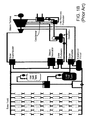
- FIG. 2 is a schematic representation of an LHTES CSP plant in accordance with the features of the present invention.
- FIG. 3A is perspective view of an LHTES system in accordance with the features of the present invention.
- FIG. 3B is a perspective view of an LHTES system featuring an insulating top and bottom;
- FIG. 4 is a plan view of the LHTES system
- FIG. 5 depicts a latent heat thermal energy storage module in accordance with the features of the present invention
- FIG. 6A is a sectional view taken along line 6 - 6 as shown in FIG. 5 ;
- FIG. 6B is a graph of temperature relative to position within a module during the discharging cycle
- FIG. 7 is a side view of the LHTES system taken along line 7 - 7 as shown in FIG. 4 ;
- FIG. 8 is a graph showing the relationship between the size of the pipe and the number of modules.
- FIG. 9 is a graph showing the relationship between the type of HTF flow and the number of modules.
- the present invention is directed to a modular LHTES system that has a particular applicability to CSP plants.
- LHTES system will be described in the context of a CSP plant, the presently invented system can be used to store energy in a variety of contexts.
- the LHTES system 20 operates downstream from solar energy collectors 7 .
- the solar energy collectors 7 as shown in FIG. 2 are parabolic troughs 8 that heat the HTF contained in pipelines 9 .
- the pipelines 9 are in thermal communication with the troughs 8 , so as to transport the HTF from the solar collector 8 and into a single inlet line 10 .
- the inlet line 10 directs the HTF to downstream power generation and thermal energy storage components.
- a first portion 10 a of the inlet line 10 transports the fluid directly to a steam-producing heat exchanger 11 so as to cause the fluid to be in thermal communication with the exchanger 11 .
- the steam generated at the heat exchanger 11 is transported to other downstream power generation components 12 , which are likely to include a steam superheater, turbine generator, and condenser.
- a second portion 10 b of the inlet line 10 directs HTF to the invented LHTES system 20 .
- the HTF can no longer absorb energy from the sun. Instead, the HTF absorbs thermal energy stored in the LHTES system 20 . This occurs when the HTF emanating from the exchanger/steam generator 11 is diverted to a latent heating system feed line 14 positioned intermediate the exchanger and the feedback loop. The feed line 14 recirculates spent HTF through a means of ingress 15 of the LHTES system 20 . Thus, the HTF absorbs energy from the LHTES system 20 . The reheated HTF is then redirected to the heat exchanger/steam generator 11 .
- a secondary or downstream loop 16 of the heat exchanger positioned intermediate the heat exchanger 11 and the power generation components, establishes thermal communication between the heat exchanger/steam generator 11 and the power generation components 12 .
- the power generation components are the final destination of the energy generated by the system 20 . This portion of the CSP plant's operation cycle is known as the “discharging cycle” because the thermal energy stored during the day is discharged during a nonoptimal time.
- FIG. 2 demonstrates use of the present invention with a parabolic trough CSP plant, other solar energy receivers are equally applicable. Further, other forms of power sources are applicable.
- the LHTES system 20 is a modular system in which a multitude of modules 30 are aggregated into a single storage cluster.
- the cluster of modules 30 is enveloped, encased or otherwise housed within thermally insulating material 32 formed as a layer or sleeve around the perimeter of the modules.
- the top 33 a and bottom 33 b of the cluster also feature insulating material 32 .
- the top 33 a and bottom 33 b are removable or open to provide access to the modules 30 .
- the top 33 a is divided into separate pieces that can be lifted off of the cluster or that can be hydraulically actuated.
- a removable top 33 a to facilitate access to the modules 30 are easily envisioned.
- the bottom 33 b features access panels for ease in uncoupling the modules.
- a variety of means can be used to provide access through the bottom 33 b to the modules 30 , such as removable panels, hinged doors, and sliding panels to name a few.
- the modules 30 are closely packed within the insulating material 32 . Close packing minimizes the amount of area necessary to store the modules 30 , which thereby maximizes energy density, i.e., the amount of energy stored in a given space. Close packing also minimizes energy loss to the environment, decreases the amount of insulating material 32 needed at the outer boundary and on the top 33 a and bottom 33 b , and reduces convective heat loss among the modules. For illustrative purposes, thirty-five modules 30 are depicted in FIGS. 3A and 4 , but an actual LHTES system 20 could accommodate hundreds or thousands of modules 30 .
- the modular arrangement of the LHTES system 20 provides the aforementioned “containerless” aspect.
- Prior art systems utilized large tanks to house the thermal energy storage medium. The size of these prior art tanks could not change in response to the fluctuating storage needs of the system. Since the ultimate amount of storage for the present system 20 is divided among individual modules 30 , the modules 30 can be added or removed as needed, and the insulating material 32 is expanded or contracted as necessary. Further, the insulating material 32 does not hold any liquid components but instead only insulates the cluster of modules 30 . Thus, construction of large containers to hold the storage medium is unnecessary, and the system is said to be “containerless.”
- the modules 30 are well insulated with the insulating material 32 .
- Suitable insulation materials are those with thermal conductivities less than 0.5 W/mK, and preferably less than 0.15 W/mK, at operational temperatures.
- suitable insulating materials 32 include Superwool®, MaftecTM, Kaowool®, and any other materials that are able to withstand temperatures over 800° C. Typically, these materials will be used as liners on a rigid support substrate. Vacuum insulation at the perimeter of the cluster is also envisioned. The vacuum can be drawn between metal plates which can withstand the high temperatures of LHTES systems for advanced CSP plants above 800 C.
- the amount of insulating material 32 necessary for a given LHTES system will vary depending on output of the power plant, the number of modules 30 , and the height and width of the modules 30 .
- the insulating material 32 must cover the surface and top and bottom of the cylindrical cluster for proper insulation.
- a salient feature of the insulating sleeve or layer is that it can be opened at one or both ends to afford easy accessibility to the modules. This results in the modules not being individually insulated. This also affords easy replacement of the modules when necessary. This further results in the possibility of a single HTF transfer manifold emanating from the egress ends of all of the modules.
- FIG. 4 is a plan view of an LHTES system 20 showing the cluster without insulating material 32 on the top 33 a but with a sleeve of insulating material surrounding the cluster of modules 30 .
- the HTF is supplied to the LHTES system 20 by the second portion 10 b of the inlet line 10 .
- the second portion 10 b of the inlet line 10 is in fluid communication with a number of inlet headers 34 , which, in turn, supply the HTF to a number of modules 30 via conduits 36 .
- the HTF has a high specific heat capacity. In that way, the fluid absorbs more thermal energy per change in degree temperature than a fluid with a lower heat capacity.
- the HTF has a relatively high heat transfer coefficient and low pumping power requirements.
- An embodiment of the invention utilizes a lithium fluoride-sodium fluoride-potassium fluoride as an HTF. This molten salt is composed of about 45-47 percent lithium fluoride, about 10-13 percent sodium fluoride, and about 40-45 percent potassium fluoride.
- An example of this HTF comprises 46.5 mol % lithium fluoride, about 11.5 mol % sodium fluoride, and 42 mol % potassium fluoride.
- FLiNaK ternary eutective alkaline metal halide salt mixture
- HTFs include: a mixture of 58% potassium fluoride and 42% zirconium fluoride, a mixture of lithium chloride and potassium chloride, and a mixture of lithium fluoride and beryllium fluoride (commonly referred to as FLiBe).
- FLiBe lithium fluoride and beryllium fluoride
- Each module 30 is comprised of a conduit 36 a portion of which extends substantially external from a jacket 38 defining an interior void of the module.
- the conduit 36 shown as generally “U” shaped, has a first leg 39 a of the U terminating in a first end 36 a and a second leg 39 b of the U terminating in the second end 36 b .
- the first leg 39 a is that portion which extends external from the jacket, while the second leg 39 b extends within the void defined by the jacket and generally parallel to the longitudinal axis of the void.
- the U bend allows both connections to the modules to be at one end of the module. This is not a requirement of the invention, but it facilitates assembly and removal of modules through the top using a hoist or a crane. Alternatively, one header could be at the bottom and the other at the top of the modules.
- the first end 36 a is in fluid communication with an inlet header 34 , so as to facilitate ingress of the HTF to the module via the first end 36 a .
- Disposed between the first end 36 a and the second end 36 b of the pipe 36 is the jacket 38 .
- the void defined by interior surfaces of the jacket is adapted to receive and retain a heat retention medium 40 thereof.
- the heat retention medium 40 may be a solid at a first temperature and a fluid at a second higher temperature.
- the HTF flows within in the pipe 36 from the first end 36 a through an upstream end 35 of the jacket and through jacketed region 38 , and towards the second end 36 b of the conduit 36 .
- the jacket 38 is sealed around the conduit 36 at the top and bottom of the jacket 38 .
- a suitable manner of forming the seal is through a high temperature braze or weld.
- the conduits 36 carry a high temperature and potentially corrosive HTF.
- material selection for the conduits must be such that their melting points are higher than the HTF.
- Inconel 617 is nickel alloy primarily containing additions of chromium, molybdenum, and iron, and it maintains its strength and corrosion resistance at high temperatures and pressures. Selecting a suitable conduit 36 requires consideration of the HTF to be used. A specific HTF will be selected for specific operational temperatures, and the HTF will have its own corrosive properties, possibly requiring the selection of a conduit 36 suited for that environment. In an LHTES system using FLiNaK, other suitable materials for the pipes 36 include Hastelloy X, Hastelloy N, and Ni-Resist 210 cast iron.
- the jacketed region 38 contains the latent heat storage medium 40 , which may include a thermal diffusion substrate 42 , so as to be confined within the void defined by internal surfaces of the jacket 38 .
- the latent heat storage medium 40 absorbs the thermal energy of the HTF.
- the latent heat storage medium 40 latently stores the thermal energy by undergoing a phase transformation from solid to liquid upon being heated by the HTF. During the phase change, the thermal energy transferred from the HTF to the latent heat storage medium 40 is used to overcome the latent heat of fusion. However, some sensible heating will take place within the medium 40 , and a temperature gradient across the medium 40 will develop.
- This temperature gradient is necessary to continuously transfer the heat from the HTF to the distal portion of the storage medium 40 so as to fully melt the solid phase into the liquid phase.
- the temperature of the storage medium at the HTF conduit 36 is higher than the melting temperature of the storage medium 40 , which is the temperature at the solid-liquid interface during charging.
- the opposite occurs, and a temperature gradient develops between the outer periphery of the medium 40 and the HTF conduit 36 . Near the conduit 36 , where the HTF is cooler, the medium 40 will cool to below its melting temperature.
- FIG. 6A a liquid-solid interface s forms between the liquid phase 40 l and the solid phase 40 s .
- FIG. 6B depicts a thermal graph, wherein the ordinate is the temperature scale and the abscissa is the distance from the center of the conduit 36 .
- T m corresponds to the melting point of the medium 40
- T o corresponds to the temperature at the outside of the pipe 36
- T i corresponds to the temperature at the inside of the pipe 36
- T b corresponds to the temperature in the bulk of the HTF.
- r o is the outside diameter of the pipe 36 and r i is the inside diameter of the pipe 36 .
- 6A depicts the temperature gradient in the module 30 during the energy discharging cycle when the temperature of the medium decreases relative to the distance of the medium from the boundary 45 or interior surface of the jacket 38 .
- the medium 40 is cooler at or near the center of the void defined by the jacket compared to regions of the medium contacting or in close spatial relation to the interior surface of the jacket.
- the jacketed region 38 is configured such that the liquid-solid interface s reaches the interior surfaces 45 of the jacketed region 38 substantially at the end of the charging cycle. If the liquid-solid interface s reached the boundary 45 during charging, then the LHTES system is less efficient because excessive sensible heating would take place. If the liquid-solid interface s never reaches the boundary 45 during charging, then the modules are too large, and significant savings in space and construction costs would be lost.
- the size of the jacketed region 38 is dependent on the HTF conduit diameter and the HTF flow rate.
- a large conduit with a high flow rate transfers more thermal energy, requiring a larger jacket size.
- a small conduit with a low flow rate therefore, requires a smaller jacket size.
- a discussion of optimal conduit size and flow rate is contained infra.
- HTF conduit flow rate that is in the low Reynolds number turbulent range of ⁇ 3000 is preferred.
- the diameter of the jacketed region is then calculated from transient analysis of the charging and discharging cycles. The transient analysis involves the calculation of the movement of the liquid-solid interface as a function of time from the beginning to the end of the charging and discharging cycles. The temperatures in the PCM/foam will deviate above or below the melting temperature at all locations over the course of the charging cycle and discharging cycles.
- the HTF After flowing through void defined by the jacketed region 38 , the HTF continues toward the second end 36 b of the conduit 36 .
- the second end 36 b of the conduit 36 is in fluid communication with an outlet header 46 , as depicted in FIG. 7 .
- the outlet header 46 is in fluid communication with the outlet line 13 , which recirculates the HTF to the pipelines 9 and the solar energy collectors 7 . This charging cycle is repeated multiple times throughout the sunny portion of a day.
- the pipe 36 has a U-shaped design in which the first end 36 a and second end 36 b of the pipe 36 are separated by a bend 48 .
- This feature allows for individual modules 30 to be independently inserted and removed from the cluster within the insulating material 32 .
- the modules 30 can easily be uncoupled from the inlet header 34 and outlet header 46 and lifted free from the module cluster in the insulation 32 . In this way, damaged modules can be replaced quickly and easily without disturbing the function of the other modules.
- the first end 36 a and the second end 36 b can be joined to the inlet header 34 and outlet header 46 in any suitable way, including but not limited to a pipe union, flare fitting, flange fitting, grooved pipe fittings, and mechanical joints. Since both the inlet header 34 and outlet header 46 reside outside of the insulating material 32 , and in this case on along the same exterior side of the container, a support structure 49 is optionally provided access to the first end 36 a and second end 36 b of the module 30 .
- the inlet header 34 could be on the opposite end of the module 30 from the outlet header 46 .
- the first end 36 a and the second end 36 b of the pipe 36 could be located together at a first end of the module 30 such that the headers 34 and 46 are positioned superior from the modules 30 and such that a module 30 can be removed from below the insulating material 32 .
- first end 36 a of the conduit 36 is in fluid communication with the inlet header 34 and the second end 36 b of the conduit 36 is in fluid communication with the outlet header 36
- first end 36 a could instead be in fluid communication with the outlet header 46 and the second end 36 b could be in fluid communication with the inlet header 34 .
- the HTF flows through the second leg 39 b of the conduit 36 first.
- valves 17 are actuated to switch between fluid flow loops.
- the valve or valves 17 on the inlet line 10 are shut, while the valve or valves 17 on the feed line 14 are opened.
- the valve or valves 17 on the outlet line 13 are shut.
- the spent HTF When flowing back to LHTES system 10 , the spent HTF is at a temperature lower than the latent heat storage medium 40 . The difference in temperature causes the HTF to absorb thermal energy from the heat storage medium 40 . Since the medium 40 was liquefied during the charging cycle, the outflow of heat will cause the medium 40 to freeze, or solidify.
- the discharging cycle will repeat during the nonoptimal times and will cease when the sunlight can be effectively captured again.
- the temperature of the latent heat storage medium 40 will not deviate more than about 100° C. from its melting temperature, and generally 100° C. or less.
- the module 30 generally comprises a HTF 36 and the jacket 38 or housing encapsulating a latent heat storage media.
- a thermal diffusion substrate 42 is homogeneously intermingled with the medium 40 .
- the latent heat storage medium 40 is a PCM with a melting temperature within the range of the plant's operational temperature. Typical operational temperatures are in the range of about 300° C. to about 1000° C. and preferably above about 700° C.
- liquid salts have been found to be suitable PCMs at these temperature ranges.
- An optimum LHTES system should have minimum and maximum operational temperatures that are within about 200° C. of each other.
- a liquid salt with a melting temperature somewhere near the middle of that range could be selected as the PCM. This helps to minimize temperature differences between the liquid salt's actual temperature and its melting temperature, i.e., minimize any potential sensible heating. Accordingly, the liquid salt must be selected based on the operational capabilities of a specific plant. Plants with a lower operational temperature range will require a salt with a lower melting temperature, while plants with a higher operational temperature range will require a liquid salt with a higher melting temperature. Liquid salt melting temperatures are commonly available to those of ordinary skill in the art.
- magnesium chloride (MgCl 2 ) has been found to be a suitable PCM.
- MgCl 2 Magnesium chloride has a melting point of 714° C. and a latent heat of fusion of 356 kJ/kg.
- PCMs having the appropriate phase-change temperature it is preferable to select the PCM with the highest heat of fusion.
- thermal diffusion substrate 42 provides a means of distributing the thermal energy from the HTF.
- thermal diffusion substrates 42 can be utilized, including fins or heat pipes projecting radially from outside surfaces of the fluid conduit 36 , homogeneous dispersions of particles throughout the medium 40 , and porous foams.
- Aligned ligament graphite foam is a suitable thermal diffusion substrate 42 given of its high thermal conductivity and resistance to corrosion from the medium 40 .
- the thermal diffusion substrate 42 can be formed outside the jacket 38 and then inserted into the jacket 38 , or the thermal diffusion substrate 42 can be formed inside the jacket 38 . Further, thermal diffusion substrate 42 can be infiltrated by the PCM inside or outside the jacket 38 .
- Thermal diffusion substrates 42 having thermal conductivities an order of magnitude higher than the PCM are suitable for offsetting the relatively low thermal conductivities of some heat storage media 40 . Further, a range of thermal conductivities can be obtained depending on the porosity of the foam comprising a single thermal diffusion substrate 42 .
- the effective thermal conductivity for combinations of magnesium chloride and aligned ligament graphite foam with 95%, 90%, 70%, and 60% porosity are 10 W/mK, 30 W/mK, 85 W/mK, and 170 W/mK, respectively.
- the effective thermal conductivity increases with increasing amount of aligned ligament graphite. However, a lower porosity corresponds to a smaller volume of PCM per module.
- the latent heat storage medium 40 and heat diffusion substrate 42 are contained in the containment vessel 44 defined by the jacket 38 .
- the containment vessel 44 is a tube of a larger diameter than that of the conduit 36 .
- the containment vessel 44 can be made of a thin walled material because of minimal strength requirements, and insulation of individual modules 30 is not required in the invented LHTES system.
- An embodiment of the fluid conduit 36 is continuous in that it is comprised of a single substrate.
- the temperature of the HTF will drop over the length of the conduit 36 .
- the temperature of the HTF must be above the melting temperature of the medium 40 along the entire length of the conduit 36 b encapsulated by the jacket. This is to ensure a complete phase transformation.
- a high temperature difference may exist between the HTF and the PCM at the HTF inlet to the module, which would decrease the energy efficiency of the system.
- the jacketed region 38 of the module 30 contains a “cascade” of media 40 .
- Cascading media 40 means that multiple PCMs are used along the length of the pipe such that the temperature difference between the HTF and the PCM is minimized along the length of the module.
- radially extended cascade paradigms are also envisioned such that lower melting media are arranged on the periphery of higher melting ones such that the media are arranged concentrically.
- PCMs are divided into two separate jacketed regions to prevent the mixing of the PCMs when melted.
- no special interface is required between the two jacketed sections because heat transfer within the jackets operates in the radial, not axial, direction.
- the jacketed regions 38 are typically preformed and can simply be slid over the conduit in succession with the highest melting temperature PCM nearest to the first end 36 a and the lowest melting temperature PCM nearest to the second end 36 b .
- the jacketed regions 38 are then sealed in place by a high temperature braze or weld.
- potassium chloride (KCl) is used in conjunction with magnesium chloride.
- Potassium chloride has a melting temperature of 770° C. and a latent heat of fusion of 359 kJ/kg. Accordingly, potassium chloride is positioned proximal to the first end 36 a of the pipe 36 where the HTF is the hottest. As the temperature of the pipe 36 transitions below 770° C. the further from the upstream end 35 of the jacket 38 , relatively lower melting media downstream of the relatively higher melting media experiences a phase change.
- the sodium chloride is used in conjunction with magnesium chloride. Sodium chloride has a melting temperature of 801° C. and a latent heat of fusion of 488 kJ/kg.
- One of the goals of the invented LHTES system is to reduce the construction and operation costs of CSP plants.
- Costs for a CSP plant can be reduced by decreasing the size and number of storage tanks required to operate the plant during nonoptimal times.
- the invented LHTES system 20 provides a greatly reduced capital cost by eliminating costly storage tanks.
- the relationship between certain characteristics within the LHTES system 20 can further reduce the costs of operating the system.
- N A total ⁇ ⁇ ( s 2 - r o 2 ) ( 2 )
- N the number of modules
- a total is the total required cross-sectional area of the PCM/foam combination in the medium 40 determined by the total energy storage
- s is the distance from the center of the module that the solid-liquid interface has traveled
- r o is the outside diameter of the HTF pipe 36 .
- a total is determined from the required plant heat storage to produce electricity during nonoptimal times and the height of the storage modules. An equation to approximate A total is
- a total ⁇ ⁇ ⁇ hL f E ( 3 )
- ⁇ is the density of the storage medium 40
- h is the height of the module 30
- L f is the latent heat of fusion of the PCM
- E is the thermal energy storage of the system. The distance s that the solid-liquid interface travels depends on the diameter of the module 30 .
- Equation 2 it can be seen that the number of pipes required depends on the outside diameter of the pipe 36 .
- the number of conduits (referred to as “pipes” in FIGS. 8 and 9 ) required for the presently invented LHTES system is drastically reduced over the range of sizes considered.
- larger diameter pipes require increased pumping power.
- the cost savings in terms of the number of modules necessary for a system with larger diameter pipes is compared to the operational costs in terms of the pumping power required.
- an HTF conduit defining an outside diameter of two inches optimally balances capital installation costs and ongoing operational costs.
- the flow rate of the HTF also has an effect on the total number of HTF conduits 36 required in the LHTES system. As can be seen in FIG. 9 , once the HTF achieves turbulent flow, the total number of pipes greatly diminishes. Continuing to increase the flow rate will continue to reduce the number of pipes. However, the volumetric flow rate and, consequently, the power needed to pump the HTF increases. Preferably, the savings in capital expenditure is compared to the long term operational costs of HTF pumping power requirements. In that sense, the flow rate is a compromise between heat transfer efficiency (high flow rate) and pumping power cost (low flow rate). The inventors determined that the optimum flow rate, in terms of heat transfer efficiency and cost, is the rate just above that necessary to achieve turbulent flow conditions at a Reynolds number of approximately 3000.
- the latent heat storage medium was magnesium chloride containing aligned ligament graphite foam as the thermal diffusion substrate.
- the PCM/foam combination had a thermal conductivity of about 30 W/mK and a foam porosity of about 90 percent, i.e., about 90 percent PCM and about 10 percent foam by volume. In an embodiment of the invention, most of the thermal conductivity is provided by the foam inasmuch as thermal conductivity of PCM alone is under approximately 0.5 W/mK.
- the HTF conduits were fabricated from Inconel 617. The HTF was FLiNaK.
- the size of the LHTES system varied according to an identified relationship between the HTF flow rate and the size of the HTF conduits.
- the inventors determined that a flow rate of 0.5 m/s and a NPS 8, SCH 10 HTF conduit (outside diameter of 219.08 mm; thickness of 3.759 mm) produced a system with the least capital installation costs.
- This system required 839 HTF conduits that were 10 m in height, which corresponds to a module cluster diameter of 33.4 m.
- the capital cost is the lowest because the fewest building materials are needed.
- a 100-MW CSP plant with an eight-hour charging cycle and a twelve-hour discharging cycle will be considered.
- This LHTES system requires 4290 modules. The modules were spaced 0.54 m from center to center, which required a module cluster diameter of 34.6 m. Magnesium chloride supported on 90% porous aligned ligament graphite was used as the latent heat storage medium.
- the HTF was FLiNaK.
- the HTF pipes were Inconel 617 of size NPS 2, SCH 120. During charging, the HTF was set to a flow rate of 0.15 m/s. During discharging, the HTF was set to a flow rate of 0.1 m/s.
- the latent heat storage medium had an initial temperature of 620° C.
- the HTF had an inlet temperature of 820° C. and an outlet temperature of 765° C.
- the HTF remained above the PCM melt temperature along substantially the entire module length, and the temperature difference between the HTF and the PCM was below approximately 100° C. throughout.
- the HTF had an inlet temperature of 607° C. and an outlet temperature of 664° C.
- the inventors performed an exergy efficiency investigation in this and the next example.
- the exergy efficiency is directly dependent on the HTF inlet and outlet temperatures.
- the inlet and outlet temperatures of the HTF are dependent on the PCM properties, the HTF conduit size, and the HTF flow rate.
- This LHTES system design produced an exergy efficiency of about 97 percent. In an embodiment of the system, 96.8 percent efficiency was realized.
- This level of exergy efficiency indicates that the energy storage process is highly reversible, i.e., the energy stored in the medium was able to be recovered without a great loss from increases in entropy. Thus, the vast amount of energy stored by the system during the daylight charging cycle is able to be recovered efficiently during discharging cycle at nonoptimal times.
- the LHTES system featured the same specifications as that of Example 2 with the exception that the module 30 was cascaded.
- One method of fabricating a cascading module is to slide each preformed PCM/foam section over the HTF pipe in succession.
- the arrow in FIG. 3A shows the direction of the sliding module to its installed position (dashed lines) within a single module configuration.
- FIG. 5 shows the direction of the sliding module to its installed position within a multi-module configuration.
- the interface between two different PCM sections is not important because the heat transfer is in the radial, not axial, direction.
- the module was comprised of equal volumes of sodium chloride and magnesium chloride.
- the magnesium chloride was positioned downstream of the sodium chloride within the latent heat storage media 40 .
- the sodium chloride section was in direct contact with the magnesium chloride section.
- the thermal diffusion substrate was aligned ligament graphite foam of 90% porosity. These changes resulted in slightly higher module outlet temperatures: 773° C. during charging and 665° C. during discharging.
- the overall exergy efficiency of this system was calculated to be 97.8%. This example shows that cascading improves overall exergy efficiency.
- the present methods can involve any or all of the steps or conditions discussed above in various combinations, as desired. Accordingly, it will be readily apparent to the skilled artisan that in some of the disclosed methods certain steps can be deleted or additional steps performed without affecting the viability of the methods.
- the present invention encompasses not only the entire group listed as a whole, but each member of the group individually and all possible subgroups of the main group. Accordingly, for all purposes, the present invention encompasses not only the main group, but also the main group absent one or more of the group members. The present invention also envisages the explicit exclusion of one or more of any of the group members in the claimed invention.
Abstract
Description
where ψoverall is the exergy efficiency of the system, ExHTF charge is the total exergy supplied by the HTF during charging and ExHTF discharge is the exergy recovered by the HTF during discharging. Since the system is well insulated, the exergy loss in the PCM during charging and discharging is negligible.
where N is the number of modules, Atotal is the total required cross-sectional area of the PCM/foam combination in the medium 40 determined by the total energy storage, s is the distance from the center of the module that the solid-liquid interface has traveled, and ro is the outside diameter of the
where ρ is the density of the
Claims (7)
Priority Applications (1)
| Application Number | Priority Date | Filing Date | Title |
|---|---|---|---|
| US14/190,664 US10330393B2 (en) | 2014-02-26 | 2014-02-26 | Modular latent heat thermal energy storage systems |
Applications Claiming Priority (1)
| Application Number | Priority Date | Filing Date | Title |
|---|---|---|---|
| US14/190,664 US10330393B2 (en) | 2014-02-26 | 2014-02-26 | Modular latent heat thermal energy storage systems |
Publications (2)
| Publication Number | Publication Date |
|---|---|
| US20150241137A1 US20150241137A1 (en) | 2015-08-27 |
| US10330393B2 true US10330393B2 (en) | 2019-06-25 |
Family
ID=53881866
Family Applications (1)
| Application Number | Title | Priority Date | Filing Date |
|---|---|---|---|
| US14/190,664 Active 2037-03-12 US10330393B2 (en) | 2014-02-26 | 2014-02-26 | Modular latent heat thermal energy storage systems |
Country Status (1)
| Country | Link |
|---|---|
| US (1) | US10330393B2 (en) |
Families Citing this family (19)
| Publication number | Priority date | Publication date | Assignee | Title |
|---|---|---|---|---|
| WO2014100096A1 (en) * | 2012-12-18 | 2014-06-26 | University Of South Florida | Encapsulation of thermal energy storage media |
| US20150211805A1 (en) * | 2014-01-29 | 2015-07-30 | Kunshan Jue-Chung Electronics Co., Ltd. | Thermostat module |
| JP6295913B2 (en) * | 2014-10-08 | 2018-03-20 | 株式会社デンソー | Heat storage system |
| DE102015000238A1 (en) * | 2015-01-08 | 2016-07-14 | Optimize Gmbh | Latent heat storage and method for its operation |
| CN105922839B (en) * | 2015-02-27 | 2020-04-10 | 马勒国际有限公司 | HVAC system for electric vehicle with extended driving distance |
| FR3040210B1 (en) * | 2015-08-20 | 2019-09-06 | Hutchinson | MODULAR ASSEMBLY FOR STORER OR BATTERY |
| FR3040207B1 (en) * | 2015-08-20 | 2020-10-30 | Hutchinson | MODULAR BLOCK AND THERMAL ENERGY STORAGE UNIT |
| US10471803B2 (en) * | 2016-01-27 | 2019-11-12 | Ford Global Technologies, Llc | Systems and methods for thermal battery control |
| US10072896B2 (en) | 2016-04-22 | 2018-09-11 | LoCap Energy, LLC | Modular thermal energy storage system |
| GB2540670B (en) * | 2016-06-22 | 2018-02-14 | Future Energy Source Ltd | A solar energy capture, energy conversion and energy storage system |
| US10533808B2 (en) | 2017-06-30 | 2020-01-14 | Uchicago Argonne, Llc | Inverse latent heat thermal energy storage system, method for capturing and releasing latent heat |
| SE543772C2 (en) * | 2019-05-14 | 2021-07-20 | Azelio Ab | Thermal energy storage assembly |
| US10876765B2 (en) | 2018-11-28 | 2020-12-29 | Element 16 Technologies, Inc. | Systems and methods of thermal energy storage |
| US11499785B2 (en) | 2019-05-15 | 2022-11-15 | Uchicago Argonne, Llc | Combined thermal energy storage and heat exchanger unit |
| US20220404103A1 (en) * | 2019-12-03 | 2022-12-22 | Graphite Energy (Assets) Pty Limited | Method and apparatus for heat storage |
| CN111306001B (en) * | 2020-03-02 | 2023-09-08 | 西安交通大学 | Wind-solar reactor system and working method thereof |
| CN112944967B (en) * | 2021-01-25 | 2023-04-11 | 杭州德尚科技有限公司 | PVT heat storage and utilization device and control method thereof |
| EP4155508A1 (en) * | 2021-09-28 | 2023-03-29 | Siemens Gamesa Renewable Energy GmbH & Co. KG | Energy storage plant and operating method |
| CN115881320B (en) * | 2022-11-08 | 2024-04-19 | 中国核动力研究设计院 | High-density phase-change heat storage system for buffering and energy storage |
Citations (17)
| Publication number | Priority date | Publication date | Assignee | Title |
|---|---|---|---|---|
| US3878888A (en) * | 1973-12-07 | 1975-04-22 | George H Seidl | Heat exchanger |
| US4524756A (en) | 1983-07-25 | 1985-06-25 | Chicago Bridge & Iron Company | Thermal energy storage tank using modular heat batteries |
| US6000438A (en) | 1998-02-13 | 1999-12-14 | Mcdermott Technology, Inc. | Phase change insulation for subsea flowlines |
| US6116290A (en) | 1999-03-16 | 2000-09-12 | J. Ray Mcdermott, S.A. | Internally insulated, corrosion resistant pipeline |
| US6889751B1 (en) * | 2000-10-04 | 2005-05-10 | Modine Manufacturing Company | Latent heat storage device |
| US6978825B1 (en) | 1998-12-31 | 2005-12-27 | Bouygues Offshore | Device and process for the heat insulation of at least one underwater pipe at great depth |
| US7316262B1 (en) * | 2004-01-26 | 2008-01-08 | Rini Technologies, Inc. | Method and apparatus for absorbing thermal energy |
| US20090109623A1 (en) * | 2007-10-31 | 2009-04-30 | Forcecon Technology Co., Ltd. | Heat-radiating module with composite phase-change heat-radiating efficiency |
| US20090211249A1 (en) * | 2008-02-27 | 2009-08-27 | Sophia Antipolis Energie Developpement | Installation for generating electrical energy from solar energy |
| US20100175689A1 (en) * | 2009-01-13 | 2010-07-15 | Hamilton Sundstrand Corporation | Catalyzed hot gas heating system for pipes |
| US7896033B2 (en) | 2002-07-01 | 2011-03-01 | Saipem S.A. | Device for thermal insulation of at least a submarine pipeline comprising a phase-change material confined in jackets |
| US20110083436A1 (en) * | 2009-10-14 | 2011-04-14 | Infinia Corporation | Systems, apparatus and methods for thermal energy storage, coupling and transfer |
| US20110286724A1 (en) * | 2010-05-19 | 2011-11-24 | Travis Goodman | Modular Thermal Energy Retention and Transfer System |
| US8273474B2 (en) | 2000-02-29 | 2012-09-25 | Illinois Institute Of Technology | Battery system thermal management |
| DE102011052868A1 (en) * | 2011-08-19 | 2013-02-21 | Rehau Ag + Co. | Latent heat storage device for temperature regulation in residential and office spaces, has latent heat storage section which fully surrounds flow channel and double line composed of inner line and outer line |
| CN102954724A (en) * | 2011-08-23 | 2013-03-06 | 林武旭 | Temperature collecting and storing device |
| US20140014299A1 (en) * | 2012-07-12 | 2014-01-16 | Aisin Seiki Kabushiki Kaisha | Chemical heat storage device |
-
2014
- 2014-02-26 US US14/190,664 patent/US10330393B2/en active Active
Patent Citations (17)
| Publication number | Priority date | Publication date | Assignee | Title |
|---|---|---|---|---|
| US3878888A (en) * | 1973-12-07 | 1975-04-22 | George H Seidl | Heat exchanger |
| US4524756A (en) | 1983-07-25 | 1985-06-25 | Chicago Bridge & Iron Company | Thermal energy storage tank using modular heat batteries |
| US6000438A (en) | 1998-02-13 | 1999-12-14 | Mcdermott Technology, Inc. | Phase change insulation for subsea flowlines |
| US6978825B1 (en) | 1998-12-31 | 2005-12-27 | Bouygues Offshore | Device and process for the heat insulation of at least one underwater pipe at great depth |
| US6116290A (en) | 1999-03-16 | 2000-09-12 | J. Ray Mcdermott, S.A. | Internally insulated, corrosion resistant pipeline |
| US8273474B2 (en) | 2000-02-29 | 2012-09-25 | Illinois Institute Of Technology | Battery system thermal management |
| US6889751B1 (en) * | 2000-10-04 | 2005-05-10 | Modine Manufacturing Company | Latent heat storage device |
| US7896033B2 (en) | 2002-07-01 | 2011-03-01 | Saipem S.A. | Device for thermal insulation of at least a submarine pipeline comprising a phase-change material confined in jackets |
| US7316262B1 (en) * | 2004-01-26 | 2008-01-08 | Rini Technologies, Inc. | Method and apparatus for absorbing thermal energy |
| US20090109623A1 (en) * | 2007-10-31 | 2009-04-30 | Forcecon Technology Co., Ltd. | Heat-radiating module with composite phase-change heat-radiating efficiency |
| US20090211249A1 (en) * | 2008-02-27 | 2009-08-27 | Sophia Antipolis Energie Developpement | Installation for generating electrical energy from solar energy |
| US20100175689A1 (en) * | 2009-01-13 | 2010-07-15 | Hamilton Sundstrand Corporation | Catalyzed hot gas heating system for pipes |
| US20110083436A1 (en) * | 2009-10-14 | 2011-04-14 | Infinia Corporation | Systems, apparatus and methods for thermal energy storage, coupling and transfer |
| US20110286724A1 (en) * | 2010-05-19 | 2011-11-24 | Travis Goodman | Modular Thermal Energy Retention and Transfer System |
| DE102011052868A1 (en) * | 2011-08-19 | 2013-02-21 | Rehau Ag + Co. | Latent heat storage device for temperature regulation in residential and office spaces, has latent heat storage section which fully surrounds flow channel and double line composed of inner line and outer line |
| CN102954724A (en) * | 2011-08-23 | 2013-03-06 | 林武旭 | Temperature collecting and storing device |
| US20140014299A1 (en) * | 2012-07-12 | 2014-01-16 | Aisin Seiki Kabushiki Kaisha | Chemical heat storage device |
Non-Patent Citations (14)
| Title |
|---|
| A.A. El-Sabali, et al., One thousand thermal cycles of magnesium chloride hexahydrate as a promising PCM for indoor solar cooking, Energy Conversion and Management 52 (2011), pp. 1771-1777. |
| C.Y. Zhao, et al., Heat transfer enhancement for thermal energy storage using metal foams embedded within phase change materials (PCMs), ScienceDirect, Solar Energy 84 (2010), pp. 1402-1412. |
| C.Y. Zhao, et al., Heat transfer enhancement of high temperature thermal energy storage using metal foams and expanded graphite, Solar Energy Materials & Solar Cells, 95 (2011), pp. 636-643. |
| Charles W. Forsberg, et al., High-Temperature Liquid-Fluoride-Salt Closed-Brayton-Cycle Solar Power Towers, Journal of Solar Energy Engineering, May 2007, vol. 129, pp. 141-146. |
| D. Zhou, et al., Experimental investigations on heat transfer in phase change materials (PCMs) embedded in porous materials, Applied Thermal Engineering 31 (2011), pp. 970-977. |
| Hamidreza Shabgard, et al., Heat transfer and exergy analysis of cascaded latent heat storage with gravity-assisted heat pipes for concentrating solar power applications, ScVerse ScienceDirect, Solar Energy 86 (2012), pp. 816-830. |
| K. Nithyanandam, et al., Computational studies on a latent thermal energy storage system with integral heat pipes for concentrating solar power, Applied Energy, 103 (2013), pp. 400-415. |
| K. Nithyanandam, et.al., Analysis and optimization of a latent thermal energy storage system with embedded heat pipes, International Journal of Heat and Mass Transfer 54 (2011) pp. 4596-4610. |
| K.W. Ng, et al., Heat Transfer in Free Convection-Dominated Melting of a Phase Change Material in a Horizontal Annulus, Int. Comm. Heat Mass Transfer, vol. 25, No. 5, (1998), pp. 631-641. |
| Piia Lamberg, et al., Numerical and experimental investigation of melting and freezing processes in phase change material storage, International Journal of Thermal Sciences 43 (2004), pp. 277-287. |
| Robynne Murray, et al., Design of a Latent Heat Energy Storage System Coupled with a Domestic Hot Water Solar Thermal System, World Renewable Energy Congress 2011-Sweden, Linkoping Sweden, May 8-13, 2011, pp. 3757-3764. |
| Weihuan Zhao, et al., High Temperature Calorimetry and Use of magnesium Chloride for Thermal Energy Storage, Renewable Energy 50 (2013) 988-993. |
| Y. Tian, et al., A numerical investigation of het transfer in phase change materials (PCMs) embedded in porous metals, Energy 36 (2011 pp. 5539-5546. |
| Zhen Yang, et al., Melting of Phase Change Materials with Volume Change in Metal Foams, Journal of Heat Transfer, (Jun. 2010), vol. 132, pp. 062301-1 to 062301-11. |
Also Published As
| Publication number | Publication date |
|---|---|
| US20150241137A1 (en) | 2015-08-27 |
Similar Documents
| Publication | Publication Date | Title |
|---|---|---|
| US10330393B2 (en) | Modular latent heat thermal energy storage systems | |
| US9541070B2 (en) | Plant for energy production | |
| US8464535B2 (en) | Systems, apparatus and methods for thermal energy storage, coupling and transfer | |
| CN102203520B (en) | Thermal vector system for solar concentration power plant | |
| US20110120669A1 (en) | Liquid metal thermal storage system | |
| US20120055661A1 (en) | High temperature thermal energy storage system | |
| CN107250706B (en) | Thermal energy storage and heat exchanger | |
| US20110100356A1 (en) | Reversible hydride thermal energy storage cell optimized for solar applications | |
| US9377246B2 (en) | High temperature solar thermal systems and methods | |
| Khandelwal et al. | Recent developments in integrated solar combined cycle power plants | |
| US20140251310A1 (en) | High temperature thermal energy storage | |
| CN102927698B (en) | Integrated heat absorption, storage and exchange device | |
| WO2010140993A1 (en) | Flow solar collector | |
| US20150316288A1 (en) | Flow Control Systems and Methods for a Phase Change Material Solar Receiver | |
| US20110290445A1 (en) | Heat Conveyance and Storage System | |
| Nayak et al. | Solar cooker study under Oman conditions for late evening cooking using stearic acid and acetanilide as PCM materials | |
| JP2016217223A (en) | Solar thermal gas turbine power generation system | |
| Rea et al. | Prototype latent heat storage system with aluminum-silicon as a phase change material and a Stirling engine for electricity generation | |
| Mathur | Heat transfer and latent heat storage in inorganic molten salts for concentrating solar power plants | |
| US11118575B2 (en) | Solar system for energy production | |
| Darwesh et al. | Thermal Enhancement of Solar Energy Storage Using Phase Change Materials. | |
| CN202188668U (en) | Heat absorption, storage and transfer integrated device | |
| US20170045264A1 (en) | Joints and Joining Methods for the Heat Transfer Fluid Circuit of Trough-Type Solar Collector Systems | |
| US11499785B2 (en) | Combined thermal energy storage and heat exchanger unit | |
| Oshman et al. | Demonstration of a thermosyphon thermal valve for controlled extraction of stored solar thermal energy |
Legal Events
| Date | Code | Title | Description |
|---|---|---|---|
| AS | Assignment |
Owner name: UCHICAGO ARGONNE, LLC, ILLINOIS Free format text: ASSIGNMENT OF ASSIGNORS INTEREST;ASSIGNORS:FRANCE, DAVID M.;YU, WENHUA;SINGH, DILEEP;AND OTHERS;REEL/FRAME:033248/0257 Effective date: 20140624 |
|
| AS | Assignment |
Owner name: ENERGY, UNITED STATES DEPARTMENT OF, DISTRICT OF C Free format text: CONFIRMATORY LICENSE;ASSIGNOR:UCHICAGO ARGONNE, LLC;REEL/FRAME:034415/0886 Effective date: 20140616 |
|
| STPP | Information on status: patent application and granting procedure in general |
Free format text: NOTICE OF ALLOWANCE MAILED -- APPLICATION RECEIVED IN OFFICE OF PUBLICATIONS |
|
| STPP | Information on status: patent application and granting procedure in general |
Free format text: PUBLICATIONS -- ISSUE FEE PAYMENT VERIFIED |
|
| STCF | Information on status: patent grant |
Free format text: PATENTED CASE |
|
| MAFP | Maintenance fee payment |
Free format text: PAYMENT OF MAINTENANCE FEE, 4TH YR, SMALL ENTITY (ORIGINAL EVENT CODE: M2551); ENTITY STATUS OF PATENT OWNER: SMALL ENTITY Year of fee payment: 4 |