EP0616093B1 - Dachgaube - Google Patents
Dachgaube Download PDFInfo
- Publication number
- EP0616093B1 EP0616093B1 EP94103704A EP94103704A EP0616093B1 EP 0616093 B1 EP0616093 B1 EP 0616093B1 EP 94103704 A EP94103704 A EP 94103704A EP 94103704 A EP94103704 A EP 94103704A EP 0616093 B1 EP0616093 B1 EP 0616093B1
- Authority
- EP
- European Patent Office
- Prior art keywords
- roof
- support
- profile
- hollow profile
- dormer
- Prior art date
- Legal status (The legal status is an assumption and is not a legal conclusion. Google has not performed a legal analysis and makes no representation as to the accuracy of the status listed.)
- Expired - Lifetime
Links
Images


Classifications
-
- E—FIXED CONSTRUCTIONS
- E04—BUILDING
- E04B—GENERAL BUILDING CONSTRUCTIONS; WALLS, e.g. PARTITIONS; ROOFS; FLOORS; CEILINGS; INSULATION OR OTHER PROTECTION OF BUILDINGS
- E04B7/00—Roofs; Roof construction with regard to insulation
- E04B7/18—Special structures in or on roofs, e.g. dormer windows
-
- E—FIXED CONSTRUCTIONS
- E06—DOORS, WINDOWS, SHUTTERS, OR ROLLER BLINDS IN GENERAL; LADDERS
- E06B—FIXED OR MOVABLE CLOSURES FOR OPENINGS IN BUILDINGS, VEHICLES, FENCES OR LIKE ENCLOSURES IN GENERAL, e.g. DOORS, WINDOWS, BLINDS, GATES
- E06B9/00—Screening or protective devices for wall or similar openings, with or without operating or securing mechanisms; Closures of similar construction
- E06B9/02—Shutters, movable grilles, or other safety closing devices, e.g. against burglary
- E06B9/08—Roll-type closures
- E06B9/11—Roller shutters
- E06B9/17—Parts or details of roller shutters, e.g. suspension devices, shutter boxes, wicket doors, ventilation openings
- E06B9/17007—Shutter boxes; Details or component parts thereof
Definitions
- the invention relates to a dormer consisting of a Front wall, two side walls and a roof, the front wall and possibly also the side walls and that Include roof windows.
- Such dormers can be prefabricated and then placed on the roof in the assembled one-piece state will.
- the dormer windows can be set up on site and be assembled.
- a prefabricated and finally attachable to the roof Dormer is from the German company name "WANIT-Fertiggauben, the crown of roof living comfort ", Wanit GmbH, 4690 Herne, issued at the "Bau 88" trade fair in Kunststoff, January 1988, known.
- the roof and two wall parts existing dormer are both the roof part and the prefabricated both wall parts from a sandwich panel, the consists of a dimensionally stable insulating layer, one of which Flat side with a relatively rigid support layer and its other flat side is connected to a cover layer.
- a prefabricated dormer, which can also be fitted in one piece, that of an outer shell made of fiber-reinforced plastic and a thermal barrier coating is from DE-U-87 13 597 known.
- the outer shell is on the inside with laminated carriers with a sandwich structure Mistake.
- a dormer according to the preamble of claim 1 is already known from FR-A-2 351 223.
- the object of the present invention is to close a dormer window create that can be assembled easily and quickly, stable which can be aligned especially during assembly, so loft bumps or differences from not parallel roof beams can be compensated and a exact alignment of the dormer window according to local conditions such as for example roof tile finishes is possible.
- the Dormer is supposed to be attached to a given one with little effort Roof structure to be adaptable.
- the support frame exists - apart from the or the Cross struts - from at least two frame parts, each of which is an adjustable length Has support frame.
- the individual frame parts can be factory-made be pre-assembled.
- Using the two adjustable length Support frames can on the one hand compensate for unevenness in the attic will.
- the entire dormer height be determined. If necessary, different means long or length-adjustable cross member differences of not exactly parallel to each other Roof beams are balanced. It is different through long cross members also possible the total depth of the Define dormer so that the front is essentially with the row of roof tiles that can be connected to the dormer window completes.
- the dormer can be used the length-adjustable support frames both in the direction at least slightly in the front and in both directions - For example, areas of 150 mm - are moved, so that an exact or desired horizontal and vertical alignment the dormer is possible.
- a length-adjustable element is already known from BE-A-457 626.
- the dormer window is easy and quick to assemble, first being a factory-made and if necessary, the front of the window and roller blinds on the load-bearing Building roof elements is attached, after which various individual elements such as cross members, side elements or side windows are arranged or used.
- the length adjustability the support frame is achieved in that it as Hollow profile, preferably as an aluminum hollow profile, with an inner profile on the bottom, in particular a rectangular one or C-shaped profile, telescopic is held.
- Hollow profile preferably as an aluminum hollow profile
- inner profile on the bottom in particular a rectangular one or C-shaped profile
- telescopic is held.
- the inner profiles of the support frames are preferably over Mounting flanges or a base plate in the attic of the Building attached, so that a firm hold of the support frame and thus also the dormer window is ensured.
- the cross members each also as a hollow profile, preferably an aluminum hollow profile, trained, one over the entire length of the same Reinforcement profile can be inserted and anchored. Since that The aforementioned outer hollow profile is often sufficient Buckling stiffness, but not sufficient bending stiffness has such a stiffening to a To prevent deflection of the cross member. This is particularly so important if the roof rests on the cross beams and is carried by them.
- the reinforcement profile is at the free end of the Cross member over this and is used for attachment to load-bearing Construction elements of the building roof. It is there possible, the reinforcement profile manufacturer with a certain length over the free end of the cross member if necessary to be slidably projecting, with a sliding area of 150 mm is sufficient in most cases. When building of the support frame, the length of the cross member is then on shortened the desired dimension. Alternatively, it is possible to use the reinforcement profile To be arranged telescopically in the cross member. In both cases, the positive connections between cross member and reinforcement profile Screwing screws into drill holes provided at the factory made in the cross member.
- the two support frames - especially at the factory - Through an upper and a lower cross strut via corner connectors connected with each other.
- the lower cross strut replaces it usually in the building roof between the rafters arranged wood change.
- the dormer construction thus at least replaces part of the previous building roof construction Avoidance of the need for a separate timber change construction, with a particularly stable dormer window is achieved. Ensure the upper and lower cross struts in addition, easy attachment and installation of the Front window.
- Triangular windows or side panels can be used as side walls without windows, which are preferably made of insulated sandwich panels exist, are used.
- a particularly advantageous embodiment is defined by that the dormer roof on the support frame, in particular the cross members of the same and the support frame itself on load-bearing Construction elements of the building roof using elongated holes having angle is attachable.
- the dormer roof on the support frame in particular the cross members of the same and the support frame itself on load-bearing Construction elements of the building roof using elongated holes having angle is attachable.
- the roof in small Areas are tilted forward so that the rainwater can run better.
- the outer Profiles for the support frame and / or the cross strut and / or the cross member formed as an approximately L-shaped hollow profiles.
- the L-shaped hollow profile and the insulating and Compensating element a rectangular cross-section, the aforementioned unit over its entire Length has an unchanged width. Is unproblematic thus an attachment of elements adjacent to the support frame to the inside of the L-shaped hollow profile.
- the L-shaped one Hollow profile in two by a partition from each other divided hollow sections. In addition to better thermal insulation this also results in good stability properties for the L-shaped hollow profile and thus the support frame.
- Expansion joint covers are on the L-shaped hollow profile or integral with it in continuation the lateral boundary on the outside on two diagonally opposite edges in the axial direction
- Expansion joint covers provided. These cover the butt line or the space between the L-shaped hollow profile and an adjacent construction element, for example a window. Also by arranging such expansion joint covers water and air can enter the Gaps between the support frame and dormers prevented will.
- the expansion joint cover also aligning elements adjoining the support frame, for example a window.
- the support frames are about halfway through Height and below the lower cross member in at least two Components can be dismantled. With that you can partially long support frames or, if necessary, the factory-made Front wall of the dormer window during transport and in narrow local areas Handle the circumstances easily.
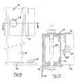
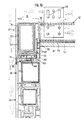
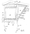
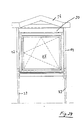
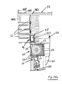
- FIG 1 shows the front of a dormer 7, which essentially consist of a support frame 10, a roof 36, a window 25 (front window) and side walls 42 (see Figure 2) exists.
- the support frame 10 comprises two horizontally spaced-apart frame parts 8 and 9, which are shown in FIG are respectively arranged to the left and right of the window 25, and Cross struts arranged above and below the window 25 16 and 18, which is an integral part of the front wall 24 of the Dormer 7 are.
- Each frame part 8, 9 consists of an upright support frame 12, 14 and one at the upper end of the respective support frame Cross member 37 arranged perpendicularly thereto (see FIG. 2).
- the support frames 12 and 14 have one at their lower end Length adjustment, which will be described later.
- At the bottom The end of each support frame 12, 14 is also a base plate 34 arranged with the attic 15 via fastening screws 68 are connectable.
- Between the support frames 12 and 14 are the two already mentioned on the front wall side, horizontally extending cross struts 16 and 18 arranged, the upper cross strut 16 between the two upper ends of the support frames 12, 14 and the lower cross strut 18 arranged approximately halfway between the two supporting frames is.
- the support frames 12, 14 and the cross struts 16, 18 roughly define the plane of the front wall 24 of the dormer window 7, while the side walls assigned by each Support frame 12 or 14 and the associated cross members 37 are defined.
- windows are suitable as windows 25, in particular Aluminum, plastic and wooden windows.
- roof 36 all types of roofs, in particular Lectern, saddle, flat, hip and conservatory roofs used will. Examples of such roofs are given below described.
- the cross struts 16, 18 and the cross member 37 are with the Support frames 12, 14 each via angles or corner connectors 38 ' connected (see FIGS. 11 and 12).
- the attachment is preferably done by means of thread cutting Screws that are screwed into prefabricated screw channels (Reference number 164).
- That between the two cross struts 16 and 18 and the two Support frames 12, 14 used window 25 includes a Window frame 26 and an openable window sash 28.
- a roller shutter box 20 is additionally provided, preferably as a mini roller shutter box, especially as Integrated roller shutter box is designed so that its dimensions are kept small and protrude from the front the dormer 7 is avoided. Will not be a roller shutter box 20 required, it can be omitted at any time will.
- a higher window can be used or the total height of the dormer can be reduced will.
- the roller shutter box 20 and the window 25 are in particular an integral part of the front and in conventionally connected together.
- the window frame 26 is also by means of thread cutting Screws on the support frame 10, in particular on the support frames 12 and 14 attached.
- a roof 36 On the support frame 10 or on the cross members 37 and possibly the cross strut 16 (see FIG. 2) is a roof 36 arranged, which with the help of elongated holes 140 Corner connectors or angles 38 or fastening tabs 38 " with the corresponding support elements, namely the cross beams 37 and / or the cross strut 16, is connected. Through the Elongated holes 140, it is also possible to cover the roof 36 in small Align areas and adjust the height of the interior lining and / or to change the inclination of the roof slightly.
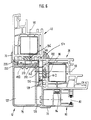
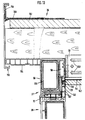
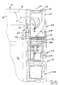
- FIG 2 is at the upper end of the support frame 12, 14 is vertical arranged cross member 37 recognizable.
- the cross member 37 consists of a hollow profile to be explained later 78, into which a reinforcing profile 120 can be inserted and anchored is.
- the reinforcement profile 120 serves the bending stiffness increase and strength of the cross member 37, so that he also the load exerted by the roof 36 without can withstand noticeable deflection.
- the reinforcement profile 120 stands at the free end of the cross member 37 above this before and is used to attach the cross member 37 and thus of the support frame 10 on load-bearing roof construction elements, in particular on a roof beam 48 or rafters.
- the reinforcement profile 120 is held firmly in the cross member 37 or in small areas - for example in the range of 150 mm - be telescopically movable. In both cases the reinforcement profile after cutting or adjusting the end projecting from the cross member 37 is connected to the latter, especially in that pre-made in the factory Drill holes screws are screwed in.
- the cross beam 37 protruding end becomes the reinforcement profile 120 using corner connectors via holes 52 with screws on Roof beams 48 or rafters attached. If necessary also a square tube between the roof-side ends of the Cross member 37 are arranged, which is usually in the Building roof construction replaced existing wood changes.
- the side wall 42 of the dormer 7 comprises in the illustrated Embodiment a triangular window 40.
- This lies with its frame on the respectively assigned support frame 12, 14 and is with this by means of thread-cutting screws 50 connected.
- an intermediate profile 39 Between the cross member 37 and the upper frame of triangular window 40 is in the embodiment of FIG Figure 2 inserted an intermediate profile 39, the upper frame of the triangular window 40 on the intermediate profile 39 and the intermediate profile 39 on the cross member 37 by means of thread cutting Screws 50 is attached. If the mini roller shutter box is omitted, The intermediate profile 39 is also omitted.
- Purpose of the intermediate profile 39 is a height difference between the bottom edge the roller shutter box 20 and the glass element of the triangular window 40 to create so that the triangular window 40 when entering or removing the glass not through the edges of the roller shutter box 20 can be damaged.
- the diagonal frame part of the triangular window 40 lies above a connecting element 60 indirectly next to the roof beam 48, so that the slope of the triangular window 40 is the slope of the building roof corresponds.
- the triangular window is made by thread cutting and extending through the intermediate profile 39 Screws on the cross member 37 and also by means of thread cutting Screws attached to the support frame profile 12, 14.
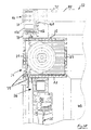
- FIGs 4 and 5 is an embodiment of the lower End of the support frame 12, 14 shown.
- the support frames 12 and 14 comprise an outer hollow profile 78, in particular a Aluminum hollow profile, in which a telescopically slidably mounted and a smaller cross-section inside Profile 32, which as a rectangular hollow or C-shaped Profile can be formed, is included.
- a concrete one Embodiment of the outer, in particular made of aluminum Hollow profile 78 is explained in more detail below.
- the free, lower end of the inner profile 32 is with the bottom plate 34 connected, in particular welded.
- the bottom plate 34 can be fastened to the building attic 15 by means of screws 68, so that the support frame 10 and thus the dormer window 7 receives a stable hold.
- the bottom plate 34 executed so that they only on one side, for example inwards, over the side wall level of the frame parts 8, 9 protrudes.
- Such a design of the base plate 34 allows a series of dormers next to each other without lying next to each other upcoming floor plates 34 hinder each other. Be too this arrangement prevents damage to the living room floor.
- Figure 6 is a sectional view through the support frame 10 shown along the line VI - VI of Figure 2.
- Sectional view is that arranged on the edge of the dormer 7 Recognizing support frame 12 to which laterally behind the frame of the triangular window 40 and laterally at the front the window frame 26 of the front window 25 connects.
- a hollow profile is used as the outer profile for the support frame 12, 14 78, in particular an aluminum hollow profile, with an L-shaped cross section provided (see also Fig. 14).
- the L-shaped hollow profile 78 is essentially by two rectangular hollow profiles formed and has two by a partition from each other separate hollow chambers 126 and 127.
- the hollow chamber 127 represents the hollow chamber into which the inner profile 32 or the reinforcing element 120 can be inserted.
- everyone Leg of the L-shaped hollow profile 78 comprises a rectangular hollow profile.
- a support bar 240 is provided at the rectangular hollow profile that the hollow chamber 126 defined. This extends parallel and at a distance to the ledge-like projection 128 and is in extension a side wall of the L-shaped hollow profile 78.
- the insulating and compensating element 132 points to the strip-like A groove 130 on the side facing the projection 128, in which the strip-like projection 128 depending on the installation Location of the insulating and compensating element 132 more or occurs less far, with the insulating and compensating element 132 through the strip-like projection 128 in the direction to the short leg or held away from it is.
- the insulating and compensating element 132 has hollow chambers 102 for thermal insulation.
- an additional heat-insulating cavity 250 is formed between the Insulating and compensating element 132 and the L-shaped hollow profile 78.
- insulating element 210 there is another insulating element on the narrow side of the long leg 210 (Fig. 15) arranged. It intervenes in the area an expansion joint cover 70 arranged on the hollow profile, extending outward and along the L-shaped hollow profile 78 Projection 230 in a correspondingly trained Groove 220 of the insulating member 210. The insulating element 210 is thus in its relative position to the L-shaped hollow profile 78 determined and aligned.
- a part of the insulating element 210 enters into the recess the projection 230 and the expansion joint cover 70 and lies against the L-shaped hollow profile 78.
- the end of the insulating element 210 is supported on one further support ledge 240, which is parallel to the projection 230 and extends spaced therefrom. This is between the L-shaped hollow profile 78 and the insulating element 210 a cavity 250 is also formed, which has an insulating effect.
- This support bar 240 also extends in an extension Side wall of the L-shaped hollow profile 78. Also heat-insulating the hollow chambers 102 act in the insulating element 210.
- the isolating and compensating element 132 and the isolating element 210 have a substantially rectangular cross section, which is dimensioned so that the unit from Isolating and compensating element 132, insulating element 210 and L-shaped hollow profile 78 an over its entire length essentially rectangular cross section.
- 14 goes the L-shaped hollow profile is thus flush with the insulating and Compensating element 132, on which in the assembled state Window frame 26 of the window 25 abuts.
- the window frame comes with the one that is preferably made of aluminum Hollow section 78 practically not in contact, so that a good one Thermal insulation is achieved.
- the insulating element 210 On the side facing the triangular side is between the L-shaped hollow profile 78 and the side part the insulating element 210 to form a flat contact surface for the adjoining dormer window element and good thermal insulation interposed.
- the insulating element 210 and the insulating and Compensating element 132 a corner-extending insulation on the inside of the L-shaped hollow profile, so that good thermal insulation - also between L-shaped hollow profiles 78 and adjacent dormer elements - is guaranteed.
- This insulation can also be promoted by a Cross-section approximately triangular and made of plastic or wood manufactured cover strip 54 along the inner corner region between the adjoining window frames of the front and Side windows and also on all other inner corner areas.
- the insulating and compensating element 132 has the ledge projection 128 facing away from an anchoring element 146 with which it is connected to the adjacent element, according to FIG 6 thus can be anchored to the frame of the triangular window 40 is.
- anchoring element 146 from a strip-like nose, which in a groove of the adjacent Elements and engages behind them.
- Expansion joint covers 70 are provided on the L-shaped hollow profile 78 .
- the L-shaped hollow profile 78 has an end face of the long leg a plurality of one another in the longitudinal direction spaced screw channels 164 on the one self-tapping screw easily in and through the Profile wall of the L-shaped hollow profile 78 is screwable, in particular for the frictional screwing of an inner Reinforcement profile, e.g. of profile 120.
- FIG. 6 it borders on one of the two Narrow sides of the support frame 12 of the frame of the triangular window 40 which, with the mentioned anchoring element 146 of the Isolating and compensating elements 132 is in locking engagement.
- the frame of the triangular window 40 is by means of a screw 50 on the support frame 12, in particular on the L-shaped hollow profile 78 attached.
- Between the frame of the triangular window 40 and the insulating member 210 is a longitudinal one Sealing element 96 arranged.
- the diagonal window frame assigned expansion joint cover 70 bridges the Joint line of both elements, i.e. the support frame 12 and 14 on the one hand and the adjacent triangular window 40 on the other hand, and covers a gap that may occur.
- the Expansion joint cover 70 therefore has a multiple function. To the one serves to align the support frame and adjacent elements. Secondly, it prevents intrusion of wind and water in the dormer structure.
- the insulating and compensating element 132 towards short leg of the L-shaped hollow profile 78 out or from can be moved away, it remains with the frame of the triangular window 40 is engaged when the triangular window 40 and the support frame 12 are not exactly aligned in parallel are. Even with such misalignment there is none direct connection between the outside environment and the interior of the Dormer possible. Rather, pointing away at a shift from the short leg of the L-shaped hollow profile 78, the insulating and compensating elements 132 a distance from the short Leg that corresponds essentially to the distance that the frame of the diagonal window 40 from the L-shaped hollow profile 78 is spaced. The misalignment is due to of the insulating and compensating element which can be moved with the window 40 132 also not visible or recognizable from the inside. There is no gap visible from the inside (see also Fig. 9).
- the window frame closes - as already mentioned above 26 of the window 25, being between the window frames 26 and the insulating and compensating element 132 also a further sealing element 96 is provided.
- Means the window frame becomes a further thread-cutting screw 50 26 on the insulating and compensating element 132 on L-shaped hollow profile 78 attached.
- roller shutter guide 80 provided a roller shutter guide mounting screw 84 can be pushed on is attached.
- the roller shutter guide 80 is on the inside of the second front expansion joint cover 70 and has a groove 82 with brushes for guiding the roller shutter.
- a alternative embodiment without roller shutter guide is shown in Fig. 20 shown.
- outer i.e. L-shaped hollow profile 78
- aluminum is particularly suitable, that is easy to work with. Since aluminum conducts heat well, it is important to form a thermal or cold bridge between the outside environment and the interior of the dormer 7 to avoid.
- the hollow chambers 102 are in the insulating and Compensation elements 132 and 210 provided.
- the particular PVC insulating and compensating element 132 or 210 is thus the interior of the dormer 7 next lying corner point of the L-shaped hollow profile 78 of spaced from this, i.e. shifted to the outside.
- the lower cross strut 18, as can be seen from FIG is, also from the aforementioned L-shaped Hollow profile 78 or the unit made of hollow profile 78, insulating element 210 and insulating and compensating element 132 formed.
- the two expansion joint covers 70 are separated here been.
- An embodiment in which the outer expansion joint cover is of course also conceivable.
- On the lying on the lower cross strut 18 is the lower part of the window frame 26 of the window 25 arranged, between Cross strut 18 and window frame 26 a sealing film 62 It is intended to extend forward to the first row of roof tiles 64, which are arranged on roof battens 58, extends and on the one hand a seal between window frames 26 and lower cross strut 18 and the other between Dormer 7 and adjacent building roof forms.
- the sealing film 62 is in particular on the adjacent building roof glued.
- sealing film 62 and the window frame 26 another parallel to the lower frame part of the window 25 extending sealing element 96 interposed.
- At the bottom Part of the window frame 26 is one on the front arranged in particular saddle rail 104 made of aluminum, which serves as an outer window sill and partly the Sealing film 62 protects.
- a veneer 136 Located on the insulating and compensating element 132 and L-shaped hollow profile 78 formed the inner contact surface of the lower cross strut 18 is a veneer 136 on the inside arranged, on which the angle profile holding element 90th for the window sill 30. The attachment of the same is done by screws 50 on the lower cross strut 18. Die Screws 50 extend through the holder 90, the veneer 136 and in the upper area near the window sill through the insulating and compensating element 132.
- the insulating and compensating element assigned to the lower cross strut 18 132 is tailored so that through window frames 26, the long leg of the L-shaped hollow profile 78 and the insulating and compensating element 132 formed a groove into which the window sill 30 enters.
- FIG 14 A lower part of the support frame can also be seen in FIG 14, which has an angle 38 on a roof beam 48 or rafters is attached.
- FIG 8 is a section through the frame of the triangular window 40 and the adjacent area shown.
- a connection element 60 is arranged, which rests on a square timber 110, which has a roof beam 48 is connected.
- a sealing film 98 is attached, which extends up to extends under the next adjacent row of roof tiles 64, being on the top of that extending under the roof tiles 64 Edge of a sealing bead, especially a foam rubber cord 97, is provided. This prevents the intrusion of water under the roof tiles 64.
- FIG 9 is a section along the line IX - IX of Figure 2, wherein in addition to the rafters 48, the cross member 37 with intermediate profile 39 arranged underneath and the can again be seen under this triangular window 40 is.
- the cross member 37 also includes an L-shaped Hollow profile 78 as described above.
- an expansion joint cover only on the outside 70 provided.
- the expansion joint cover 70 provided is at the cross member 37 severed.
- the Expansion joint cover 70 the joint line of both elements or covers any space that may occur.
- Isolundund Compensation element 132 Inside the L-shaped hollow profile 78 is the Isolundund Compensation element 132 connected to the intermediate profile 39. It also serves as a compensating element in the one described above Wise. Accordingly, here too Isolating and compensating element 132 a direct route from the outside prevented in the space enclosed by the dormer 7, if the upper cross member 37 and the intermediate profile 39 are not are aligned exactly parallel to each other. Will continue thermal insulation by the insulating and compensating element 132 provided so that the formation of a heat or Cold bridge is prevented.
- the reinforcement profile 120 which in this embodiment is designed as a rectangular hollow profile.
- the reinforcement profile 120 is by means of screws 50 L-shaped hollow profile 78 fixed.
- Inside borders on the Cross member 37 a cladding forming the ceiling of the dormer 142 and above this a vapor barrier 144.
- cross member 37 additionally by means of an angle 38 on the roof beam 48 or rafters is attached.
- the angle 38 has elongated holes 140 on so that even after attaching the angle 38 this and thereby the cross member 37 is slightly displaceable and can be aligned.
- each support frame 12, 14 is constructed in two parts. It is approximately at the level of the windowsill 30 and below the cross strut 18 for transportation or can be dismantled for handling in confined spaces. Both Parts 150, 152 consist of the aforementioned L-shaped hollow profile 78. Both parts are by means of a a smaller diameter connecting profile 108, which also serves as a reinforcement profile. Either the lower and the upper part of the support frame 12, 14 by means of thread-cutting screws on the connection profile 108 fixed.
- FIG. 11b Another alternative is shown in Fig. 11b.
- the lower support frame part 150 has been dispensed with.
- the inner profile 32 is extended so far upwards, that it is instead of the connection profile 108 in the upper part the support frame enters.
- the attachment between the support frame and inner profile 32 takes place as shown in Fig. 4 and is already explained above.
- the inner profiles 32 are from the outside not to be seen.
- this alternative offers one cheaper manufacturing option because part of the expensive Support frames in favor of the cheaper inner Profile 32 can be omitted.
- FIG. 11c shows an embodiment modified compared to FIG. 11a a connection between an upright support frame - here Support frame 14, consisting of the hollow profile 78 mentioned - and the lower cross strut 18, also from the mentioned Hollow profile 78 can be made shown.
- a connecting angle 38 extends into the front Hollow profile of the lower cross strut 18 on the support frame 14 screwed (screw 50) connecting profile 67 according to Art a connecting pin into it.
- a rigid connection between Cross strut 18 and support frame 14 then takes place by itself screwed transversely through cross strut 18 and connecting profile 67 Connection screws 50.
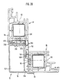
- FIG. 13 shows an embodiment with a flat roof to recognize the support frame 10.
- the flat roof is 36 on the cross member reinforced by the reinforcement profile 120 37 and is surrounded by an attic end profile 156. Between the parapet end profile 156 and the cross member 37 is a roof cladding 154 below the roof 36 arranged.
- a chipboard 162 is provided, on which in turn a roof film 160 rests, which extends to the parapet end profile 156 and on this is fastened with a clamping rail 158.
- the Roof film 160 prevents water, moisture or the like prevented in the roof structure.
- the cross member 37 and the roof are by angle 38 and mounting tabs 38 "connected together.
- the angle or the fastening tabs 38, 38 have elongated holes 140, so that alignment of the roof 36 is possible in certain areas is.
- the fact that the L-shaped hollow profile 78 for both Support frames 12, 14, the cross member 37 and the cross struts 16 and 18 can be used is a particularly affordable one Production possible because there are only a few different parts must be provided.
- the L-shaped hollow profile 78 can consist of aluminum as described above and has a cross-sectional dimension in a specific embodiment of about 90 x 60 x 25 mm. It can be plastic coated or be provided with a film covering.
- the windowsill 30 can be made of PVC, wood, or other materials consist. Especially when using PVC and Wood also insulates the windowsill 30, so that over the lower Cross strut 18 no cold bridge can be formed.
- the inner veneer 136 is made of wood, plaster or the like Materials.
- the dormers 7 described above can be simple and can be assembled quickly. For example, assembly times of about 2 hours realistic.
- the Support frame 10 set up which can be telescoped through the length-adjustable ends of the support frames 12, 14 and if necessary, the cross member 37 can be precisely aligned.
- the Roof beams 40 or rafters can be roughly level with the windowsill 30 an angle with elongated holes on both the support frames 12, 14 and attached to the roof beam 48 be, the support frames 12, 14 and so the Support frame 10 in both the horizontal and vertical directions is slightly displaceable and alignable.
- the telescopically nested profiles fixed and the Final dimensions thus determined.
- the cross member 37 After building the window and blinds comprising factory-made front the cross member 37 with the support frames 12, 14th connected by corner connector. Then the cross member 37 if necessary at the roof end using a square tube connected so that a wood replacement set in the building roof is.
- the roof 36 is on the cross member 37th put on and connected by means of the angle 38. It can the roof 36 as shown in FIG. 2 is shown with a Insulation 122 are provided, so that also over the roof area no cold or heat penetrate into the interior of the dormer 7 can. Also all alternative roofs offered, in particular the three type roofs listed above, can be arranged on the dormer in the aforementioned manner will.
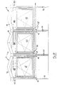
- FIG. 19 is a partial section through a front of a Roof dormer construction shown, with the edge areas two juxtaposed dormer windows described above are shown.
- the two contiguous are clear Support frames 12 and 14 can be seen between which sealing and joint elements are arranged.
- From one to another window frame 26 bridges a cover 168 the two adjoining support frames 12, 14 and at least partially the window frame 26. It is used for one for insulation and the other for optical design the inside of the dormer window.
- the cover 168 is by means of Screws attached to the window frame.
- Fig. 18 From Fig. 18 it can be seen, for example, that it is nevertheless is possible, the front is not at right angles to the To have dormer side parts connected. This is particularly so then the case when a hexagonal dormer-like dormer to be formed.
- the factory-made front then has a sectional shape that is equilateral Matches trapezoid without a base.
- the connection of the front 18 can be seen from the side parts.
- the Window frame 26 of the front lies over a pivot point 170 on the support frame 12, 14, being outside the fulcrum 170 to cover the by tilting from the front and side wall of the resulting gap 172 an aperture 174 arranged between support frame 12, 14 and window frame 26 is.
- Each between panel 174 and support frame 12, 14 or Front window frame 26 is a pinch seal, so that no moisture and no wind enter the gap 172 can.
- the front is attached to the support frames 12, 14 medium screws. With the aforementioned dormer shape extends that assigned to the support frames 12, 14 Insulating and compensating element 132 from the triangular windows or side walls 42 to the front window 25 and also serves to beautify the interior view of the dormer window.
- This dormer has a pent roof 36.
- FIG. 22 A flat roof according to FIG. 22 is equally possible.
- the gable roof shown in Fig. 23 has already been used 1 and 11b explained.
- the embodiments according to the Fig. 21 to 23 is common that the foremost, in the 21 to 23 roof trusses not visible at height the upper cross strut or immediately behind it is. How this can be achieved constructively can e.g. B.
- Fig. 31 recognize, based on the aforementioned construction is explained in more detail. Accordingly, in the embodiments 21f the roof, in particular its front edge, compared to that described above Embodiments lowered. Accordingly, it can be position the entire roof lower with the advantage that a larger window area can be achieved with the same external dimensions is.
- FIG. 24 the dormer window according to FIG. 23 is a schematic Shown front view. A comparison with Fig. 1 leaves very clearly recognize that in the embodiment according to FIG. 24 the lower edge of the saddle roof 36 immediately above the roller shutter box lies while in the embodiment of Fig. 1 the gable roof only begins above the cross strut 16.
- Fig. 26 shows an upper corner connection between the cross strut 16, cross member 37 and support frame 12 in section, directly behind the support frame 16 by the cross member 37 and the intermediate profile and window frame parts arranged underneath through it.
- Both the upper cross strut 16 and the cross member 37 and the support frame 12 each consist of a hollow profile 78 corresponding to FIG. 14.
- the cross strut 16 is at the upper end of the support frame, not shown 12 connected, specifically via a connecting bracket 38.
- the horizontal leg of the connecting angle 38 extends into the hollow profile 78 of the upper cross strut 16 and is screwed there (connecting screw 50).
- the vertical leg the connection angle 38 is with the inner side wall the hollow profile forming the support frame 12 is screwed. This screw connection is also with the reference number 50 indicated.
- the cross member 37 is at the upper end of the support frame 12 forming hollow profile 78 butt connected, namely by means of one, preferably two, connecting angles 38
- Number of connection brackets 38 depends on both the cross member 37 as well as the cross strut 16 on the length of these components from.
- the upper connection angle 38 extends with its horizontal leg on the front into the hollow profile 78 of the cross member 37 and there screwed to the top wall of hollow section 78 (connecting screw 50).
- connection angle 38 is similar to the cross strut 16 with the Screwed to the rear wall of the hollow profile 78 forming the supporting frame 12. In the present case there are four screw connections intended. The corresponding holes for the connecting screws are identified in FIG. 26 by reference number 53.
- connection bracket 38 On the underside of the hollow profile forming the cross member 37 78 a further connection bracket 38 is connected. To this is the horizontal leg of the lower connection angle 38 with the lower boundary wall of the hollow profile 78 screwed (connecting screw 50). The vertical leg of the lower connection angle 38 is the same as that Vertical leg of the upper connecting angle 38 with the Back of the hollow frame 78 forming the support frame 12 is screwed. The holes provided for this in the vertical leg are also identified by reference number 53.
- the horizontal leg of the lower connection angle 38 is between two at the bottom of the cross member 37 forming Hollow profile 78 formed longitudinal webs 230, 240 fitted.
- the vertical leg is fitted in the same way both the upper connection angle 38 and of the lower connection angle 38 between the two aforementioned Longitudinal webs on the back of the support frame 12 forming hollow profile 78.
- This non-rotatable connection is especially important if connected to the cross members 37 Roof trusses exerted high torques on the cross member 37 will.
- the mentioned longitudinal webs 230, 240 are therefore not used only for the formation of heat-insulating cavities 250 in connection with the compensating and insulating elements 132, 210 (see Fig. 17), but also have the function of corresponding Fasteners, e.g. B. the connection angles described above 38, a non-rotatable connection between cross members 37 and associated support frame 12 ensure.
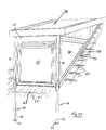
- connection angle 43 for a roof truss 44 or the like, as shown in Fig. 31 is shown from below in the gap between the strip-like projection 128 and the associated side of the parallel leg of the L-shaped Hollow profile 78 can be inserted.
- insertable Leg of the connection angle 43 is dimensioned so that the connection angle 43 with its lower corner edge here on one ledge-like projection 128 formed opposite Longitudinal web 240 can be supported. The connection angle is 43 held securely on the cross member 37.
- connection bracket 43 Preferably also another screw connection of the vertical leg of the connection bracket 43 with the cross member 37 in that described above Wise.
- the roof truss 44 are on the horizontal leg of the connecting bracket 43 the roof truss 44 supported. So these extend to Height of the cross member 37 or at the level in Fig. 31 not front cross struts shown 16. In this way leaves move the roof 36 down as far as possible.
- FIG. 27 the upper corner connection is corresponding to FIG. 26 shown in top view.
- the fitting described above of the vertical leg of both the upper and lower connection angle 38 between the protruding outwards on the back Longitudinal webs 230, 240 of the support frame 12 forming Hollow profile 78 is shown very clearly in FIG. 27.
- the triangle becomes for a gable roof 36 between the upper cross strut 16 and the roof 36 by means of Plastic profiles 32 covered.
- Plastic profiles 32 covered.
- the connection between neighboring Plastic profiles 32 is a tongue and groove connection. Instead of plastic profiles, wooden or Metal profiles are used.
- Fig. 32 is a corner connection in horizontal section for a bay window, the corner element being that in FIG. 14
- the hollow profile 78 shown is used in connection with the on the basis of the 15 to 17 compensating and insulating elements explained in more detail 132, 210.
- This corner element or hollow profile 78 close window frames that are also used in dormer windows kind on, each with the interposition of strip-like Sealing elements 96.
- Regarding this connection reference is made to the description in FIG. 20.
- Hollow sections 78 can not only be used as dormers, but also bay windows or conservatories with high thermal insulation produce.
- the hollow profile 78 is a universally usable profile, for which accordingly protection is claimed separately.
- tubular corner connector is preferred 35, 36 via a plate-like Support element 65 can be supported on the ground, which is on a a base plate 34 upstanding threaded bolt 66 can be unscrewed.
- the screw height of the support element 65 can either by a lock nut or by a Fix the cross bolt.
- roof trusses are preferred from a standard masonry board with the dimensions 4500 x 270 x 5 mm. With this, the trusses for a pent roof, gable roof as well as flat roof or Manufacture the arched roof. In this respect, the desired construction hardly any limits.
Description
- Fig. 1
- eine schematische Vorderansicht einer Ausführungsform einer Dachgaube mit Stützrahmen und werksseitig eingesetztem Fenster,
- Fig. 2
- eine schematische Seitenansicht der Dachgaube aus Figur 1,
- Fig. 3
- eine schematische Vergrößerung eines Ausschnitts aus Figur 2 mit Anschlußende des Querträgers,
- Fig. 4
- eine schematische Vergrößerung eines Ausschnittes aus Figur 2 mit längenverstellbarem Ende der Stützzarge,
- Fig. 4a
- eine Darstellung entsprechend Fig. 4 mit abgewandelter Verbindung zwischen den teleskopierbaren Teilen einer Stützzarge,
- Fig. 5
- eine Schnitt-Draufsicht auf das innere Profil mit Bodenplatte der Stützzarge eines Stützrahmens gemäß Figur 2,
- Fig. 5a
- die Ausführungsform einer Stützzarge gemäß Fig. 4a im Schnitt längs Linie V-V in Fig. 4a,
- Fig. 6
- eine schematische Teilschnittansicht durch den Stützrahmen längs Linie VI-VI aus Figur 2,
- Fig. 7
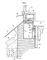
- eine schematische Teilschnittansicht durch den Stützrahmen längs Linie VII-VII aus Figur 1,
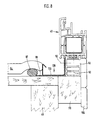
- Fig. 8
- eine schematische Teilschnittansicht längs Linie VIII-VIII aus Figur 2,
- Fig. 9
- eine schematische Teilschnittansicht längs Linie IX-IX aus Figur 2,
- Fig. 10
- eine schematische Teilschnittansicht längs Linie X-X aus Figur 2,
- Fig. 11a
- eine schematische Vergrößerung eines Ausschnitts XI aus Figur 1 gemäß einer alternativen Ausführungsform der Erfindung,
- Fig. 11b
- eine schematische Vorderansicht einer weiteren Ausführungsform einer Dachgaube mit Stützrahmen und werksseitig eingesetztem Fenster,
- Fig. 11c
- eine zu Fig. 11a alternative Verbindung zwischen Stützzarge und unterer Querstrebe bzw. Brüstungsriegel in schematischer Vorderansicht,
- Fig. 12
- eine schematische Teilschnittvergrößerung eines Ausschnitts XII aus Figur 2,
- Fig. 13
- eine schematische Schnittvergrößerung eines Bereiches in dem das Dach auf den Querträger aufliegt,
- Fig. 14
- eine schematische Schnittdarstellung eines Ausführungsbeispiels eines L-förmigen Hohlprofils,
- Fig. 15
- eine schematische Detailschnittansicht eines Isolierelements für das L-förmige Hohlprofil,
- Fig. 16
- eine schematische Detailschnittansicht einer Ausführungsform eines Isolier- und Ausgleichselements für das L-förmige Hohlprofil,
- Fig. 17
- eine schematische Schnittdarstellung eines Ausführungsbeispiels einer Baueinheit aus L-förmigem Hohlprofil sowie Isolier- und Ausgleichselementen,
- Fig. 18
- eine schematische und vergrößerte Schnittdarstellung einer eine Stützzarge umfassenden Kante für eine Dachgaube mit Sechseck-Erker,
- Fig. 19
- eine schematische Detailschnittansicht eines Bereichs zweier aneinandergrenzender Dachgaubenfronten,
- Fig. 20
- eine schematische Teilschnittansicht durch den Stützrahmen wie Fig. 6, jedoch ohne Rolladenführung,
- Fig. 21
- eine perspektivische Ansicht einr Dachgaube gemäß Erfindung mit Pultdach,
- Fig. 22
- eine perspektivische Ansicht einr Dachgaube gemäß Erfindung mit Flachdach,
- Fig. 23
- eine perspektivische Ansicht einr Dachgaube gemäß Erfindung mit Satteldach,
- Fig. 24
- eine schematische Vorderansicht einer abgewandelten Ausführungsform einer Dachgaube mit Stützrahmen und werksseitig eingesetztem Fenster sowie im Vergleich zu der Ausführungsform gemäß Fig. 1 tiefergelegtem Dach,
- Fig. 25
- die Ausführungsform gemäß Fig. 24 in schematischer Seitenansicht unter Darstellung der Einbauvariationen,
- Fig. 26
- eine obere Eckverbindung zwischen dem die obere Seite einer Seitenwand der Dachgaube begrenzenden Querträger (Rückansicht) und einer oberen, die beiden Stützzargen miteinander verbindenden Querstrebe (im Schnitt),
- Fig. 27
- die Eckverbindung gemäß Fig. 26 in Draufsicht,
- Fig. 28
- die obere Eckverbindung entsprechend Fig. 26 unter Darstellung einer zwischen der oberen Querstrebe und dem Fensterrahmen eingepaßten Rolladenkasten im Schnitt und in Teilansicht,
- Fig. 28a
- eine Darstellung entsprechend Fig. 28 und Darstellung des vorderen Abschlusses eines Satteldachs,
- Fig. 29
- drei nebeneinander angeordnete und zu einer Einheit miteinander verbundene Dachgauben in Vorderansicht,
- Fig. 30
- einen Teil der Ausführungsform gemäß Fig. 29 in vergrößertem Maßstab und unter Darstellung der oberen Eckverbindungen und oberen Verbindung zwischen zwei benachbarten Dachgauben,
- Fig. 31
- die obere Verbindung zwischen zwei benachbarten Dachgauben in noch weiter vergrößertem Maßstab,
- Fig. 32
- eine Eckverbindung eines Viereckerkers im Horizontalschnitt,
- Fig. 33 und 34
- ein Verbindungselement für den Anschluß an eine Rundprofilstütze für einen Erker in Seitenansicht sowie Draufsicht, und
- Fig. 35 und 36
- ein Bodenstützelement für eine Rundprofil-Stütze für einen Erker in Seitenansicht und Draufsicht.
Claims (32)
- Dachgaube, bestehend aus einer Vorderwand (24), zwei Seitenwänden (42) und einem Dach (36), wobei die Vorderwand (24) und ggf. auch die Seitenwände (42) sowie das Dach (36) Fenster (25, 40) umfassen,dadurch gekennzeichnet, daßwobei die Dachgaube weiter einen Stützrahmen (10) mit wenigstens zwei in im Einbauzustand horizontalem Abstand voneinander angeordneten Rahmenteilen (8, 9) aufweist, von denen jedes eine aufrechte Stützzarge (12, 14), die mit ihren unteren Enden am Dachboden (15) eines Gebäudes anschließbar ist, und in etwa senkrecht zu den Stützzargen (12, 14) angeordnete Trägerelemente (37) aufweist, die mit ihren freien Enden an einem tragenden Konstruktionselement des Gebäudes, insbesondere am Dachbalken (48) oder -sparren anschließbar sind, wobeiweiterhin die beiden Stützzargen (12, 14) durch wenigstens eine Querstrebe (16, 18) zu einer Baueinheit miteinander verbunden sind, und wobeidie beiden Stützzargen (12, 14) und die wenigstens eine Querstrebe (16, 18) im Bereich der Vorderwand (24) und die senkrecht zu den Stützzargen (12, 14) angeordneten Trägerelemente jeweils im Bereich der beiden Seitenwände (42) der Dachgaube liegen,die Trägerelemente als Querträger (37) ausgebildet sind,die Querträger (37) jeweils am oberen Ende der Stützzargen (12, 14) anschließbar sind, unddie Stützzargen (12, 14) längsverstellbar sind, so daß am Boden Unebenheiten ausgeglichen werden können und/oder eine gewünschte Höhe des Fensters (25) über dem Dachboden (15) einstellbar ist.
- Dachgaube nach Anspruch 1,
dadurch gekennzeichnet,
daß die Stützzargen (12, 14) ein äußeres Profil, insbesondere ein Hohlprofil (78), umfassen, in dem bodenseitig ein inneres Profil (32), insbesondere ein rechteckförmiges oder C-förmiges Profil, teleskopartig verschiebbar gehalten ist. - Dachgaube nach Anspruch 1 oder 2,
dadurch gekennzeichnet,
daß die Stützzargen (12, 14) am Dachboden (15) des Gebäudes mit dem jeweils inneren Profil (32) anschließbar sind, wobei zu diesem Zweck am freien, bodenseitigen Ende des jeweils inneren Profils (32) ein Befestigungsflansch oder eine Bodenplatte (34) vorgesehen ist. - Dachgaube nach einem der Ansprüche 1 bis 3,
dadurch gekennzeichnet,
daß der Befestigungsflansch bzw. die Bodenplatte (34) so angeordnet ist, daß sie im montierten Zustand nicht über die äußere seitliche Begrenzung der Seitenwand (42) vorsteht. - Dachgaube nach einem der Ansprüche 1 bis 4,
dadurch gekennzeichnet,
daß die Querträger (37) jeweils als Hohlprofil ausgebildet sind, in dessen Hohlraum, vorzugsweise über die ganze Länge desselben, ein Verstärkungsprofil (120) zur Versteifung und Verstärkung des entsprechenden Querträgers (37) einschiebbar, insbesondere längenveränderbar einschiebbar, und verankerbar ist. - Dachgaube nach Anspruch 5,
dadurch gekennzeichnet,
daß das Verstärkungsprofil (120) am freien Ende des Querträgers (37) über diesen vorsteht und zur Befestigung des Querträgers (37) an tragende Konstruktionselemente des Gebäudedaches, insbesondere an Dachbalken (48) oder -sparren, anschließbar ist. - Dachgaube nach einem der vorhergehenden Ansprüche,
dadurch gekennzeichnet,
daß zwischen den beiden Querträgern (37) und/oder zwischen den beiden Stützzargen (12, 14) zumindest ein Stützelement, insbesondere ein Vierkantrohr, angeordnet ist, das zur Stabilisierung der Dachgaube und des Gebäudedaches dient und ggf. im Gebäudedach vorhandene Holzwechsel ersetzt. - Dachgaube nach einem der vorhergehenden Ansprüche,
dadurch gekennzeichnet,
daß die beiden Stützzargen (12, 14) vorderwandseitig durch eine obere (16), insbesondere an den beiden oberen Enden der Stützzarge (12, 14), und eine untere (18), etwa auf halber Höhe derselben angeordnete Querstrebe miteinander verbunden sind, wobei zwischen den beiden Querstreben (16, 18) ein Fensterrahmen (26) und gegebenenfalls zwischen diesem und der oberen Querstrebe (16) ein Rolladenkasten (20), insbesondere Mini-Rolladenkasten, einsetzbar oder eingesetzt ist. - Dachgaube nach einem der vorhergehenden Ansprüche,
dadurch gekennzeichnet,
daß zumindest eine, insbesondere die obere Querstrebe (16) als Hohlprofil ausgebildet ist, in deren Hohlraum, vorzugsweise über die gesamte Länge derselben, ein Verstärkungsprofil (120) zur Versteifung und Verstärkung einschieb- und verankerbar ist. - Dachgaube nach einem der Ansprüche 2 bis 9,
dadurch gekennzeichnet,
daß die gegenseitige Relativlage der äußeren Profile, insbesondere der äußeren Hohlprofile (16, 18, 37, 78), und der inneren Profile (32, 120) durch Querbolzen oder - schrauben (50), insbesondere gewindeschneidende Schrauben, fixierbar ist. - Dachgaube nach einem der Ansprüche 8 bis 10,
dadurch gekennzeichnet,
daß die Querstreben (16, 18) und der Fensterrahmen (26) mit der Stützzarge (12, 14) und ggf. miteinander mittels Schrauben (50), insbesondere gewindeschneidenden Schrauben verbunden sind. - Dachgaube nach einem der Ansprüche 1 bis 11,
dadurch gekennzeichnet,
daß die beiden Seitenwände (42) jeweils ein Dreieckseitenteil oder Dreieckfenster (40) umfassen, das ggf. unter Zwischenschaltung eines Zwischen- (39) oder Ausgleichprofils am Querträger (37) einerseits und der aufrechten Stützzarge (12, 14) andererseits befestigbar ist, wobei die Diagonalseite der Seitenwand (42) entweder unmittelbar oder mittelbar auf einem zugeordneten Dachbalken (48) oder -sparren aufsitzt. - Dachgaube nach einem der vorhergehenden Ansprüche,
dadurch gekennzeichnet,
daß das Dach (36) am Stützrahmen (10), insbesondere an den Querträgern (37) und ggf. der oberen Querstrebe (16) desselben, und der Stützrahmen (10) selbst an tragenden Konstruktionselementen des Gebäudedaches mittels Langlöcher aufweisender Winkel (38) oder Befestigungslaschen (38") derart befestigbar ist, daß nach einer anfänglichen Fixierung oder Anheftung eine Verschiebung der miteinander zu verbindenden Teile, insbesondere eine Horizontalverschiebung und/oder Vertikalverschiebung des Stützrahmens (10) sowie eine entsprechende Verschiebung und ggf. Einstellung der Neigung des Dachs (36) möglich ist. - Dachgaube nach einem der vorhergehenden Ansprüche,
dadurch gekennzeichnet,
daß als äußeres Profil für die Stützzarge (12, 14) und/oder die Querstrebe (16, 18) und/oder den Querträger (37) ein etwa L-förmiges Hohlprofil (78) vorgesehen ist, wobei an der Innenseite des kürzeren Schenkels ein parallel zum längeren Schenkel verschiebbares, insbesondere aus PVC bestehendes Isolier- und Ausgleichselement (132) angeordnet ist. - Dachgaube nach Anspruch 14,
dadurch gekennzeichnet,
daß das Isolier- und Ausgleichselement (132) einem im wesentlichen rechteckigen Querschnitt aufweist, wobei die Dicke desselben der Breite der Innenseite des kürzeren Schenkels des L-förmigen Hohlprofils (78) entspricht, so daß die aus Isolier- und Ausgleichselement (132) und L-förmigem Hohlprofil (78) bestehende Einheit über ihre gesamte Länge einen im wesentlichen rechteckförmigen Querschnitt aufweist. - Dachgaube nach Anspruch 14 oder 15,
dadurch gekennzeichnet,
daß an der Innenseite des kürzeren Schenkels des L-förmigen Hohlprofils (78) ein sich in Längsrichtung erstreckender, von der Innenseite des längeren Schenkels beabstandeter sowie parallel dazu verlaufender, leistenartiger Vorsprung (128) vorgesehen ist, der mit einer an der dem leistenartigen Vorsprung (128) zugewandten Seite des Isolier- und Ausgleichselements (132) ausgebildeten Nut (130) derart zusammenwirkt, daß das Isolier- und Ausgleichselement (132) in Richtung zum kurzen Schenkel hin oder von diesem weg verschiebbar gehalten ist. - Dachgaube nach einem der Ansprüche 14 bis 16,
dadurch gekennzeichnet,
daß das Isolier- und Ausgleichselement (132) Hohlkammern (102) zur Wärmeisolierung aufweist. - Dachgaube nach einem der Ansprüche 14 bis 18,
dadurch gekennzeichnet,
daß das Isolier- und Ausgleichselement (132) an der dem leistenartigen Vorsprung (128) abgewandten Seite ein Verankerungselement (146) aufweist, mit dem es mit an die Einheit aus Isolier- und Ausgleichselement (132) und L-förmigem Hohlprofil (78) anschließenden Elementen verankerbar ist. - Dachgaube nach einem der Ansprüche 14 bis 18,
dadurch gekennzeichnet,
daß an der im montierten Zustand innen liegenden Schmalseite des langen Schenkels des L-förmigen Hohlprofils (78) ein Isolierelement (210) fixierbar ist. - Dachgaube nach Anspruch 19,
dadurch gekennzeichnet,
daß das Isolier- und Ausgleichselement (132) einerseits und das Isolierelement (210) andererseits eine Übereck-Isolierung an der Innenseite des L-förmigen Hohlprofils (78) bilden. - Dachgaube nach Anspruch 19 oder 20,
dadurch gekennzeichnet,
daß am Isolierelement (210) eine Nut (220) ausgebildet ist, in die ein am L-förmigen Hohlprofil (78) angeordneter Vorsprung (230) eingreift. - Dachgaube nach einem der Ansprüche 14 bis 21,
dadurch gekennzeichnet,
daß das L-förmige Hohlprofil (78) durch zwei durch eine Trennwand voneinander getrennte Rechteck-Hohlprofile mit Hohlkammern (126, 127) gebildet ist, wobei jeder Schenkel des L-förmigen Hohlprofils (78) ein Reckteckprofil umfaßt. - Dachgaube nach einem der Ansprüche 14 bis 22,
dadurch gekennzeichnet,
daß am L-förmigen Hohlprofil (78) oder integral mit diesem in Fortsetzung der seitlichen Begrenzung außenseitig an zwei diagonal gegenüberliegenden Kanten, in Axialrichtung verlaufende Dehnfugenabdeckungen (70) vorgesehen sind. - Dachgaube nach einem der Ansprüche 14 bis 23,
dadurch gekennzeichnet,
daß die L-förmigen Hohlprofile (78) aus Aluminium bestehen. - Dachgaube nach einem der Ansprüche 14 bis 24,
dadurch gekennzeichnet,
daß die L-förmigen Hohlprofile (78) kunststoffbeschichtet, folienummantelt oder dgl. sind. - Dachgaube nach einem der vorhergendenden Ansprüche,
dadurch gekennzeichnet,
daß innenseitig an oder unterhalb der unteren Querstrebe (18) eine Fensterbank (30) angeordnet ist. - Dachgaube nach einem der vorhergehenden Ansprüche,
dadurch gekennzeichnet,
daß jede Stützzarge (12, 14) etwa auf halber Höhe, unterhalb der unteren Querstrebe (18) in zumindest zwei Bestandteile zerlegbar ist, die insbesondere durch ein in die einzelnen Bestandteile teleskopartig einschiebbares Verbindungselement (108) miteinander ausrichtbar und verbindbar sind. - Dachgaube nach einem der Ansprüche 1 bis 27,
dadurch gekennzeichnet,
daß die zumindest aus den Stützzargen (12, 14), dem Fenster und ggf. den Querstreben (16, 18) sowie dem Rolladenkasten (20) bestehende Vorderseite werkseitig vorgefertigt ist und mit den die Dachgaube vervollständigenden Seitenelementen (37, 42) sowie dem Dach zusammenfügbar ist. - Dachgaube nach einem der Ansprüche 14 bis 28,
dadurch gekennzeichnet,
daß die Querträger (37) und/oder die Querstreben (16, 18) jeweils mittels Verbindungswinkel (38) stumpf an eine Stützzarge (12, 14) anschließbar sind, und zwar bei den Querträgern (37) insbesondere mittels eines oberen, mit einem Schenkel in das Hohlprofil (78) eines Querträgers (37) einführbaren und darin verschraubbaren ersten Verbindungswinkels (38) und eines unteren, mit dem einen Schenkel drehfest zwischen zwei an der Unterseite nach außen vorstehenden Längsstegen (230, 240) des den Querträger (37) definierenden Hohlprofils (78) einerseits und mit dem anderen Schenkel zwischen zwei an der Rückseite ebenfalls nach außen vorstehenden Längsstegen (230, 240) eines die Stützzarge (12, 14) definierenden Hohlprofils (78) andererseits einpaßbaren zweiten Verbindungswinkels (38). - Dachgaube nach einem der Ansprüche 14 bis 28,
dadurch gekennzeichnet,
daß die die Querstreben (16, 18) und/oder Querträger (37) bildenden Hohlprofile (78) jeweils so an den Stützzargen (12, 14) angeschlossen sind, daß der leistenartige Vorsprung (128) jeweils innenseitig liegt und nach unten gerichtet ist, so daß der eine Schenkel eines inneren Anschlußwinkels (43) für einen Dachbinder (44) oder dgl. von unten her in den Spalt (129) zwischen dem leistenartigen Vorsprung (128) und der diesem zugewandten Seite des sich parallel dazu erstreckenden Schenkels des L-förmigen Hohlprofils (78) einfügbar ist. - Dachgaube nach Anspruch 30,
dadurch gekennzeichnet,
daß der mit dem einen Schenkel in den durch den leistenartigen Vorsprung (128) definierten Spalt (129) eingeführte Anschlußwinkel (43) mit seiner Eckkante an einem dem leistenartigen Vorsprung (128) gegenüberliegend ausgebildeten Längssteg (249) abstützbar ist. - Dachgaubensystem bestehend aus zumindest zwei Dachgauben, die nach einem der vorhergehenden Ansprüche 1 bis 31 ausgebildet sind, wobei die mindestens zwei Dachgauben zu einer Kniestockkonstruktion nebeneinander angeordnet sind.
Applications Claiming Priority (6)
| Application Number | Priority Date | Filing Date | Title |
|---|---|---|---|
| DE4308918 | 1993-03-19 | ||
| DE4308918 | 1993-03-19 | ||
| DE4316296 | 1993-05-14 | ||
| DE4316296 | 1993-05-14 | ||
| DE4338597A DE4338597C2 (de) | 1993-03-19 | 1993-11-11 | Hohlprofil zur Verwendung bei der Herstellung einer Dachgaube, eines Wintergartens, eines Erkers oder dergleichen |
| DE4338597 | 1993-11-11 |
Publications (2)
| Publication Number | Publication Date |
|---|---|
| EP0616093A1 EP0616093A1 (de) | 1994-09-21 |
| EP0616093B1 true EP0616093B1 (de) | 1998-01-28 |
Family
ID=27204878
Family Applications (1)
| Application Number | Title | Priority Date | Filing Date |
|---|---|---|---|
| EP94103704A Expired - Lifetime EP0616093B1 (de) | 1993-03-19 | 1994-03-10 | Dachgaube |
Country Status (3)
| Country | Link |
|---|---|
| EP (1) | EP0616093B1 (de) |
| AT (1) | ATE162873T1 (de) |
| DE (3) | DE4338597C2 (de) |
Cited By (3)
| Publication number | Priority date | Publication date | Assignee | Title |
|---|---|---|---|---|
| DE19925111C1 (de) * | 1999-06-01 | 2000-11-23 | Fassaden Praktiker Ost West Ve | Dachgaube |
| DE19919699C1 (de) * | 1999-04-17 | 2001-01-18 | Fassaden Praktiker Ost West Ve | Dachgaube |
| DE19908717C1 (de) * | 1999-03-01 | 2001-03-22 | Fassaden Praktiker Ost West Ve | Dachgaube |
Families Citing this family (4)
| Publication number | Priority date | Publication date | Assignee | Title |
|---|---|---|---|---|
| DE9404363U1 (de) * | 1994-03-15 | 1994-05-19 | Michael Christoph Gmbh | Dachgaube |
| AT410458B (de) | 2001-08-23 | 2003-05-26 | Matausch Bernhard Ing | Flexible dachgaube |
| NL1027205C2 (nl) * | 2004-10-08 | 2006-04-19 | Ubbink Bv | Dakraamsamenstel. |
| FR2890674B1 (fr) * | 2005-09-14 | 2009-04-10 | Coin Freres Sarl | Lucarne de toiture equipee d'un volet roulant |
Family Cites Families (18)
| Publication number | Priority date | Publication date | Assignee | Title |
|---|---|---|---|---|
| BE457626A (de) * | ||||
| FR1023789A (fr) * | 1950-08-26 | 1953-03-24 | Construction d'une charpente de toit | |
| US2767669A (en) * | 1952-03-17 | 1956-10-23 | Modern Metal Craftsmen Inc | Tubular support for awning roofs |
| DE2101483B2 (de) * | 1971-01-14 | 1973-02-01 | Sparrendach | |
| CH533743A (fr) * | 1971-01-28 | 1973-02-15 | Diffusion De Materiel Tech G M | Cloison horizontale |
| US3863419A (en) * | 1971-09-09 | 1975-02-04 | John H Hendrich | Method of constructing a foldable building |
| US3760550A (en) * | 1972-01-20 | 1973-09-25 | Armco Steel Corp | Collapsible truss structure |
| FR2234434A1 (en) * | 1973-06-21 | 1975-01-17 | Ferodo Sa | Prefabricated roof frame trimmer - has two pairs of rafters between which are hinged fillet pieces |
| DE7510392U (de) * | 1975-01-25 | 1975-07-31 | Beile G Kg | Dachgaubenfertigaufbau mit Elementen |
| FR2351223A1 (fr) * | 1976-05-11 | 1977-12-09 | Vercelletto Antoine | Procede de construction de charpentes et charpentes ainsi realisees |
| FR2546941B1 (fr) * | 1983-06-02 | 1986-03-28 | Norpac | Lucarne prefabriquee |
| DE3508581C1 (de) * | 1985-03-11 | 1986-08-28 | HAMA-Alu & Holzbauwerk GmbH, 8303 Rottenburg | Dachgaube |
| DK541186D0 (da) * | 1986-11-12 | 1986-11-12 | Sarnak Innovationsaktieselskab | Bygningskvist |
| DE8713597U1 (de) * | 1987-09-25 | 1987-12-03 | Eternit Ag, 1000 Berlin, De | |
| GB8816776D0 (en) * | 1988-07-14 | 1988-08-17 | Mills D L | Extendible structural beam |
| DE8905436U1 (de) * | 1989-04-29 | 1990-06-21 | Dickgreber, Hans, Dipl.-Ing., 4780 Lippstadt, De | |
| DE4022962A1 (de) * | 1989-07-24 | 1991-01-31 | Alwin Hoernschemeyer | Profil- und gelenksystem fuer die erstellung von dachstuehlen |
| DE9112318U1 (de) * | 1991-10-04 | 1991-12-12 | Roeders, Peter, 4050 Moenchengladbach, De |
-
1993
- 1993-11-11 DE DE4338597A patent/DE4338597C2/de not_active Expired - Lifetime
-
1994
- 1994-03-10 DE DE59405134T patent/DE59405134D1/de not_active Expired - Lifetime
- 1994-03-10 AT AT94103704T patent/ATE162873T1/de not_active IP Right Cessation
- 1994-03-10 EP EP94103704A patent/EP0616093B1/de not_active Expired - Lifetime
- 1994-03-18 DE DE9404632U patent/DE9404632U1/de not_active Expired - Lifetime
Cited By (3)
| Publication number | Priority date | Publication date | Assignee | Title |
|---|---|---|---|---|
| DE19908717C1 (de) * | 1999-03-01 | 2001-03-22 | Fassaden Praktiker Ost West Ve | Dachgaube |
| DE19919699C1 (de) * | 1999-04-17 | 2001-01-18 | Fassaden Praktiker Ost West Ve | Dachgaube |
| DE19925111C1 (de) * | 1999-06-01 | 2000-11-23 | Fassaden Praktiker Ost West Ve | Dachgaube |
Also Published As
| Publication number | Publication date |
|---|---|
| DE4338597C2 (de) | 2001-07-12 |
| DE9404632U1 (de) | 1994-05-19 |
| EP0616093A1 (de) | 1994-09-21 |
| ATE162873T1 (de) | 1998-02-15 |
| DE59405134D1 (de) | 1998-03-05 |
| DE4338597A1 (de) | 1994-09-22 |
Similar Documents
| Publication | Publication Date | Title |
|---|---|---|
| EP1861553B1 (de) | Selbsttragende raumzelle mit nichttragenden vorgesetzten aussenwänden | |
| EP3504386B1 (de) | Modulhaus | |
| EP3835507B1 (de) | Hilfssparren, dachfensteranordnung sowie dachanordnung | |
| DE102009023883B4 (de) | Fassadenelement | |
| DE102018121776A1 (de) | Zarge für Fenster und Türen sowie Fenster- oder Türelement mit einer solchen | |
| EP0147502B1 (de) | Überdachung mit mindestens einem verschiebbaren Dachteil | |
| EP0616093B1 (de) | Dachgaube | |
| DE19615306A1 (de) | Bausatz zur Erstellung eines Daches durch Fertigdachelemente mit integrierten Großkollektoren | |
| DE3435648A1 (de) | Dach- und wand-waermedaemmsystem | |
| EP1019593B1 (de) | Bausatz für eine dachunterkonstruktion eines geneigten daches | |
| EP0612900A1 (de) | Montagehaus | |
| DE3532846C2 (de) | Bauelement zur Erstellung von Gebäuden, auch zur Erstellung von Gebäudemodellen | |
| EP0070962B1 (de) | Aus vorgefertigten Teilen bestehendes montierbares Gebäude | |
| CH656413A5 (de) | Wandelement. | |
| DE3837377C2 (de) | Flachdach-Dämmkeil | |
| DE19743846C2 (de) | Sattel- oder Krüppelwalmdach | |
| DE10006492A1 (de) | Haus mit Fertigbauelementen für den leicht handhabbaren Eigenbau | |
| DE102005011970A1 (de) | Fertiggebäude | |
| AT410458B (de) | Flexible dachgaube | |
| DE19531441C1 (de) | Ausgefachte Fachwerkkonstruktion, Bausatz und Verfahren zum Errichten einer ausgefachten Fachwerkkonstruktion | |
| DE4237074C2 (de) | Bausatz zum Erstellen einer Loggia | |
| DE19919699C1 (de) | Dachgaube | |
| DE3905953A1 (de) | Dachgaube | |
| EP1854931B1 (de) | Verfahren für die Errichtung von Massivholzhäuser | |
| DE102009005413A1 (de) | Bausatz zur Herstellung von Überdachungen |
Legal Events
| Date | Code | Title | Description |
|---|---|---|---|
| PUAI | Public reference made under article 153(3) epc to a published international application that has entered the european phase |
Free format text: ORIGINAL CODE: 0009012 |
|
| AK | Designated contracting states |
Kind code of ref document: A1 Designated state(s): AT BE CH DE DK ES FR GB GR IE IT LI LU MC NL PT SE |
|
| K1C1 | Correction of patent application (title page) published |
Effective date: 19940921 |
|
| 17P | Request for examination filed |
Effective date: 19950310 |
|
| RBV | Designated contracting states (corrected) |
Designated state(s): AT BE CH DE DK FR GB IT LI LU NL SE |
|
| 17Q | First examination report despatched |
Effective date: 19951116 |
|
| GRAG | Despatch of communication of intention to grant |
Free format text: ORIGINAL CODE: EPIDOS AGRA |
|
| GRAG | Despatch of communication of intention to grant |
Free format text: ORIGINAL CODE: EPIDOS AGRA |
|
| GRAH | Despatch of communication of intention to grant a patent |
Free format text: ORIGINAL CODE: EPIDOS IGRA |
|
| GRAH | Despatch of communication of intention to grant a patent |
Free format text: ORIGINAL CODE: EPIDOS IGRA |
|
| GRAA | (expected) grant |
Free format text: ORIGINAL CODE: 0009210 |
|
| AK | Designated contracting states |
Kind code of ref document: B1 Designated state(s): AT BE CH DE DK FR GB IT LI LU NL SE |
|
| PG25 | Lapsed in a contracting state [announced via postgrant information from national office to epo] |
Ref country code: NL Free format text: LAPSE BECAUSE OF FAILURE TO SUBMIT A TRANSLATION OF THE DESCRIPTION OR TO PAY THE FEE WITHIN THE PRESCRIBED TIME-LIMIT Effective date: 19980128 Ref country code: IT Free format text: LAPSE BECAUSE OF FAILURE TO SUBMIT A TRANSLATION OF THE DESCRIPTION OR TO PAY THE FEE WITHIN THE PRE;WARNING: LAPSES OF ITALIAN PATENTS WITH EFFECTIVE DATE BEFORE 2007 MAY HAVE OCCURRED AT ANY TIME BEFORE 2007. THE CORRECT EFFECTIVE DATE MAY BE DIFFERENT FROM THE ONE RECORDED.SCRIBED TIME-LIMIT Effective date: 19980128 Ref country code: GB Free format text: LAPSE BECAUSE OF FAILURE TO SUBMIT A TRANSLATION OF THE DESCRIPTION OR TO PAY THE FEE WITHIN THE PRESCRIBED TIME-LIMIT Effective date: 19980128 Ref country code: FR Free format text: LAPSE BECAUSE OF FAILURE TO SUBMIT A TRANSLATION OF THE DESCRIPTION OR TO PAY THE FEE WITHIN THE PRESCRIBED TIME-LIMIT Effective date: 19980128 |
|
| REF | Corresponds to: |
Ref document number: 162873 Country of ref document: AT Date of ref document: 19980215 Kind code of ref document: T |
|
| REG | Reference to a national code |
Ref country code: CH Ref legal event code: EP |
|
| REF | Corresponds to: |
Ref document number: 59405134 Country of ref document: DE Date of ref document: 19980305 |
|
| PG25 | Lapsed in a contracting state [announced via postgrant information from national office to epo] |
Ref country code: LU Free format text: LAPSE BECAUSE OF NON-PAYMENT OF DUE FEES Effective date: 19980310 Ref country code: AT Free format text: LAPSE BECAUSE OF NON-PAYMENT OF DUE FEES Effective date: 19980310 |
|
| PG25 | Lapsed in a contracting state [announced via postgrant information from national office to epo] |
Ref country code: LI Free format text: LAPSE BECAUSE OF NON-PAYMENT OF DUE FEES Effective date: 19980331 Ref country code: CH Free format text: LAPSE BECAUSE OF NON-PAYMENT OF DUE FEES Effective date: 19980331 Ref country code: BE Free format text: LAPSE BECAUSE OF NON-PAYMENT OF DUE FEES Effective date: 19980331 |
|
| PG25 | Lapsed in a contracting state [announced via postgrant information from national office to epo] |
Ref country code: SE Free format text: LAPSE BECAUSE OF FAILURE TO SUBMIT A TRANSLATION OF THE DESCRIPTION OR TO PAY THE FEE WITHIN THE PRESCRIBED TIME-LIMIT Effective date: 19980428 Ref country code: DK Free format text: LAPSE BECAUSE OF FAILURE TO SUBMIT A TRANSLATION OF THE DESCRIPTION OR TO PAY THE FEE WITHIN THE PRESCRIBED TIME-LIMIT Effective date: 19980428 |
|
| EN | Fr: translation not filed | ||
| NLV1 | Nl: lapsed or annulled due to failure to fulfill the requirements of art. 29p and 29m of the patents act | ||
| GBV | Gb: ep patent (uk) treated as always having been void in accordance with gb section 77(7)/1977 [no translation filed] |
Effective date: 19980128 |
|
| BERE | Be: lapsed |
Owner name: BOHN ALFRED Effective date: 19980331 |
|
| REG | Reference to a national code |
Ref country code: CH Ref legal event code: PL |
|
| PLBE | No opposition filed within time limit |
Free format text: ORIGINAL CODE: 0009261 |
|
| STAA | Information on the status of an ep patent application or granted ep patent |
Free format text: STATUS: NO OPPOSITION FILED WITHIN TIME LIMIT |
|
| 26N | No opposition filed | ||
| PGFP | Annual fee paid to national office [announced via postgrant information from national office to epo] |
Ref country code: DE Payment date: 20030527 Year of fee payment: 10 |
|
| PG25 | Lapsed in a contracting state [announced via postgrant information from national office to epo] |
Ref country code: DE Free format text: LAPSE BECAUSE OF THE APPLICANT RENOUNCES Effective date: 20040203 |