EP0613673B2 - Austrittsdüse für Badewanne zum Erzeugen eines Luft- und/oder eines Wassersprudels - Google Patents
Austrittsdüse für Badewanne zum Erzeugen eines Luft- und/oder eines Wassersprudels Download PDFInfo
- Publication number
- EP0613673B2 EP0613673B2 EP93120649A EP93120649A EP0613673B2 EP 0613673 B2 EP0613673 B2 EP 0613673B2 EP 93120649 A EP93120649 A EP 93120649A EP 93120649 A EP93120649 A EP 93120649A EP 0613673 B2 EP0613673 B2 EP 0613673B2
- Authority
- EP
- European Patent Office
- Prior art keywords
- water
- air
- tub
- valve body
- tub according
- Prior art date
- Legal status (The legal status is an assumption and is not a legal conclusion. Google has not performed a legal analysis and makes no representation as to the accuracy of the status listed.)
- Expired - Lifetime
Links
- XLYOFNOQVPJJNP-UHFFFAOYSA-N water Substances O XLYOFNOQVPJJNP-UHFFFAOYSA-N 0.000 claims description 184
- 230000007704 transition Effects 0.000 claims description 11
- 238000007689 inspection Methods 0.000 claims description 6
- 239000012528 membrane Substances 0.000 claims description 5
- 238000005192 partition Methods 0.000 claims description 5
- 239000000463 material Substances 0.000 claims description 4
- 230000000295 complement effect Effects 0.000 claims description 3
- 239000004033 plastic Substances 0.000 claims description 2
- 230000005540 biological transmission Effects 0.000 description 31
- 238000004140 cleaning Methods 0.000 description 13
- 230000006835 compression Effects 0.000 description 3
- 238000007906 compression Methods 0.000 description 3
- 230000002093 peripheral effect Effects 0.000 description 3
- 238000007789 sealing Methods 0.000 description 3
- 239000011324 bead Substances 0.000 description 2
- 238000007664 blowing Methods 0.000 description 2
- 239000000645 desinfectant Substances 0.000 description 2
- 239000007788 liquid Substances 0.000 description 2
- 244000052616 bacterial pathogen Species 0.000 description 1
- 230000015572 biosynthetic process Effects 0.000 description 1
- 230000000249 desinfective effect Effects 0.000 description 1
- 239000003599 detergent Substances 0.000 description 1
- 230000000694 effects Effects 0.000 description 1
- 238000012423 maintenance Methods 0.000 description 1
- 238000004659 sterilization and disinfection Methods 0.000 description 1
Images


Classifications
-
- A—HUMAN NECESSITIES
- A61—MEDICAL OR VETERINARY SCIENCE; HYGIENE
- A61H—PHYSICAL THERAPY APPARATUS, e.g. DEVICES FOR LOCATING OR STIMULATING REFLEX POINTS IN THE BODY; ARTIFICIAL RESPIRATION; MASSAGE; BATHING DEVICES FOR SPECIAL THERAPEUTIC OR HYGIENIC PURPOSES OR SPECIFIC PARTS OF THE BODY
- A61H33/00—Bathing devices for special therapeutic or hygienic purposes
- A61H33/60—Components specifically designed for the therapeutic baths of groups A61H33/00
- A61H33/601—Inlet to the bath
- A61H33/6021—Nozzles
- A61H33/6063—Specifically adapted for fitting in bathtub walls
-
- A—HUMAN NECESSITIES
- A61—MEDICAL OR VETERINARY SCIENCE; HYGIENE
- A61H—PHYSICAL THERAPY APPARATUS, e.g. DEVICES FOR LOCATING OR STIMULATING REFLEX POINTS IN THE BODY; ARTIFICIAL RESPIRATION; MASSAGE; BATHING DEVICES FOR SPECIAL THERAPEUTIC OR HYGIENIC PURPOSES OR SPECIFIC PARTS OF THE BODY
- A61H33/00—Bathing devices for special therapeutic or hygienic purposes
- A61H33/02—Bathing devices for use with gas-containing liquid, or liquid in which gas is led or generated, e.g. carbon dioxide baths
- A61H33/026—Gas nozzles specially adapted therefor
-
- A—HUMAN NECESSITIES
- A61—MEDICAL OR VETERINARY SCIENCE; HYGIENE
- A61H—PHYSICAL THERAPY APPARATUS, e.g. DEVICES FOR LOCATING OR STIMULATING REFLEX POINTS IN THE BODY; ARTIFICIAL RESPIRATION; MASSAGE; BATHING DEVICES FOR SPECIAL THERAPEUTIC OR HYGIENIC PURPOSES OR SPECIFIC PARTS OF THE BODY
- A61H33/00—Bathing devices for special therapeutic or hygienic purposes
- A61H33/02—Bathing devices for use with gas-containing liquid, or liquid in which gas is led or generated, e.g. carbon dioxide baths
- A61H2033/023—Bathing devices for use with gas-containing liquid, or liquid in which gas is led or generated, e.g. carbon dioxide baths with means in the air supply lines to prevent back-feed of water, e.g. anti-backflow valves, draining devices
-
- A—HUMAN NECESSITIES
- A61—MEDICAL OR VETERINARY SCIENCE; HYGIENE
- A61H—PHYSICAL THERAPY APPARATUS, e.g. DEVICES FOR LOCATING OR STIMULATING REFLEX POINTS IN THE BODY; ARTIFICIAL RESPIRATION; MASSAGE; BATHING DEVICES FOR SPECIAL THERAPEUTIC OR HYGIENIC PURPOSES OR SPECIFIC PARTS OF THE BODY
- A61H33/00—Bathing devices for special therapeutic or hygienic purposes
- A61H33/60—Components specifically designed for the therapeutic baths of groups A61H33/00
Definitions
- the first power transmission element can do so be designed so that it even on the air valve body exerts a restoring force in the closing direction, which for example the case is when the power transmission element is resilient bellows or membrane-like
- the measures proposed for the air outlet nozzle are also largely suitable for the water outlet nozzle, which is therefore advantageously a tightly sealing water valve, which under the pressure of the water supply to the tub interior can be opened against the action of a restoring force is. This ensures secure locking at all times of the water pipe system against intrusion Water from the tub interior and / or moisture avoided from the bathtub environment, but at the same time a simple opening of the water outlet nozzle for bathtub operation under education a water bubbler or water / air bubbler guaranteed.
- the water valve advantageously has a water valve body, which opens against the flow direction of the pressurized water in the The tub interior stands out from the water valve seat.
- the pressurized water preferably acts over a second actuator on the water valve body in a direction which is the direction of flow of the water in the tub interior is opposite
- the second actuator has a Pressure of the pressurized water evading bellows, membrane or piston-shaped power transmission element with which the water valve body over a e.g. rod-shaped second connecting member non-positively communicates
- the second power transmission element can a restoring force even on the water valve body Exercise the closing direction, for example as a resilient element, such as a bellows or a Membrane is formed.
- a defined restoring force for the water valve body is achieved in particular when the restoring force exercised by a second return spring which is on the second pressurizing surface of the second power transmission element opposite side of the power transmission element acts.
- the water valve body can be used for good guidance have a front sliding portion which free of play in a water outlet channel in the front wall or the front view cap of the nozzle housing is led.
- the Water valve body preferably a rear conical Closing section, which with a complementary conical water valve seat interacts.
- the air valve body and / or the water valve body can be made of flexible material such as rubber or Made of plastic to achieve high tightness.
- the accessibility of the interior of the nozzle housing and the functional elements in it can be ensured that the nozzle housing on its rear, e.g. expanded like a chamber End of which is preferably cap-like trained exchangeably detachably held first Power transmission element is completed in this Case has the power transmission element, for example the shape of a hat membrane.
- nozzle housing in one Air chamber and a water chamber divided The each chamber is from the first or second Power transmission element limited so that a sufficiently large area for pressurization available
- the second power transmission element by means of a Removable fastening cap on a housing section kept interchangeable, making maintenance to Ensuring the functioning of the water outlet nozzle is facilitated.
- the second can be used to save space Power transmission element having part of the water chamber be arranged within the air chamber.
- At least one air access connection opens into the air chamber and a water inlet connection into the water chamber.
- a water outlet connection is provided which the cleaning medium, which over the Water access connection gets into the water chamber, can exit again.
- In the Invention is in a partition wall between air chamber and water chamber a transition valve is provided, which only towards the water chamber opens.
- the transfer valve is during the operating phase closed during the cleaning phase but open during the cleaning phase Hot air from the air chamber into the water chamber and in the water piping system for cleaning and Disinfection purposes exceeded. Conversely, can but no water from the water chamber into the air chamber reach.
- the transition valve can, for example, as Check valve be formed, whichever is closed when there is water in the water chamber located, i.e. during the operating phase.
- the water chamber can be filled with water beforehand the opening of the check valve under to prevent air pressure.
- the nozzle housing can be used to simplify assembly in a front section, which for example remains firmly attached to the tub wall, and a rear, e.g. Chamber-like enlarged section be divided, the sections e.g. by means of a Mounting bracket held together easily detachable are.
- the rear section of the chamber, which essential functional parts of the invention Feeder contains, can thus easily Inspection purposes.
- Water outlet jet or the air outlet jet one given form, e.g. the massage effect to mitigate or change.
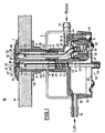
- the feeder has a nozzle housing 23, which from a front approximately cylindrical housing section 4 and a rear to a split Chamber extended housing section 7 is made.
- the front housing section 4 is by means of an external thread 44 and a threaded nut 45 on the Outside of the tub wall W fixed and supports with a front peripheral flange 46 on the Inner surface of the tub wall W from.
- the peripheral flange 46 is the outer continuation of a front one End wall 27 of the housing section 4.
- the rear larger section 7 of the nozzle housing 23 has one front cylindrical section in the area of the transition to the front housing section 4 and a rear chamber-like extension to form a Air chamber 39 and a water chamber 40, which forward into an air supply duct 24 of the air outlet nozzle 21 and a water supply channel 25 of the Skip water outlet nozzle 23.
- the rear housing section 7 is detachable by means of a mounting bracket 5 to the front one held in the tub wall W. Housing section 4 held.
- the air supply duct 24 and the water supply duct 25 are complete with the help of a partition wall 42 separated from each other and they end in two of their own Outlet openings 15 and 16 in the tub interior 26. Furthermore, they can each be closed and opened, so that air alone or water alone or air and water each adjustable in the tub space 26 can be supplied, with simultaneous Water and air supply mixing the two Rays only in the tub water in the tub interior 26 in the vicinity of the feed device takes place for this purpose the two outlet openings 15, 16 immediately next to each other in one End wall 27 and / or a face cap 1 of the nozzle housing 23.
- the air outlet nozzle 21 has an air valve, which of an air valve body 14 and an air valve seat 28 is formed.
- the air valve body 14 is over a first rod-shaped connecting member 13 from one trained as a helical compression spring first return spring 12 with its front conical Closing section 47 against that on the back the end wall 27 formed conical air valve seat 28, ie towards the tub interior 26, pressed.
- the first return spring is supported for this purpose 12 at its front end on a shoulder 48 of the first connecting member 13 and on her rear end on a shoulder 49 of the nozzle housing 23 from.
- the air valve body 14 has a front partially cylindrical and frontal curved sliding section 50, which is free of play in the Air outlet opening 16 of the end wall 27 or the viewing cap 1 is performed.
- the rear one at its rear end Chamber-like expanding housing section 7 is with provided a side air inlet connection 18.
- the the air valve body 14 against opposite rear End wall of the rear housing section 7 is as membrane-like first power transmission element 11 formed, the effective first pressurizing surface 30 the rear, from the one via the air inlet connection 18 supplied compressed air acted upon rear surface 31 of the air valve body 4 significantly, that is to say many times.
- the membrane-like power transmission element 11 is made of flexible material, such as rubber, and is with its outer angled edge detachable over the free rear end of the rear housing section 7 put up for better mounting there is Circumferential bead 51 is formed on the rear housing section 7.
- the power transmission element 11 Approximately in the middle of the membrane-like power transmission element 11 is the rear end of the first connecting member 13 non-positively but releasably added. For this purpose, the power transmission element 11 a bulge in its front wall 52 and the rear end of the first Connection member 13 locking projections. The first power transmission element 11 and the first connecting member 13 thus form next to the return spring 12 a first actuating device 29 for the Air valve body 14.
- the air valve body 14 is immediately from the return spring 12 with considerable closing force back towards the tub interior 26 in his Closed position pressed on the air valve seat 28. On this is for a hermetic seal worried, which among other things is prevented from being accidentally Tub water into the interior of the nozzle housing 23 or even enters the air supply line.
- the front wall of the first power transmission element 11 of the first actuator 29 may, as in a manometer, so designed that they themselves a restoring force in the closing direction of the air valve body 14 exercises
- the water outlet nozzle 22 is also tight final water valve, which under the Pressure of the water supply to the tub interior 26 can be opened against the action of a restoring force for this purpose the water valve has a water valve body 2, which to open against the flow direction of the pressurized water into the tub interior 26 with its conical closing section 38 of the lifts complementary conical water valve seat 32, if the pressurized water for the formation of a water vortex pending With a front area cylindrical and rounded forward sliding section 36, the water valve body 2 is free of play in the Water outlet opening 15 of the front wall 27 of the front Housing section 4 or the viewing cap 1 guided.
- the leading to the water outlet opening 15 Water supply channel 25 opens into the back expanding water chamber 40 in the housing section 41, which is provided within the air chamber 39 is. It opens into the water chamber 40 Water inlet connection 17 and from it branches a water outlet connection 20 from.
- the one opposite the water valve body 2 Wall of the housing portion 41 is membrane-like second power transmission element 8, its effective second pressurizing surface 34 the rear, from which via the water inlet connection 17 supplied pressurized water acted area 35 of the water valve body 2 substantially, that is many times over.
- the second power transmission element 8 is made of flexible material such as rubber with its outer bead-like edge using an in the housing section 41 screwed fastening cap 9 releasably on the housing section 41 held.
- the rear end of the second Connecting member 3 detachably accommodated which has the water valve body at its front end 2 carries
- the second power transmission element 8 a bulge 53 and that rear end of the connecting member 3 locking projections 54 on.
- the tub equipped according to the invention can because of the hermetic seal of the water outlet nozzle 22 a reliable cleaning of the Water piping system with either water without or with cleaning and / or disinfectant or also take place with hot air, for which in the latter case a suitable lockable connection between Air pipe system and water pipe system is provided. In all cases an exit from Detergent and / or disinfectant in the tub interior avoided.
- the air pipe system too including the air chamber 39 and the Air supply duct 24 can be blown dry using hot air become. In this case, the design would be 1 the air chamber 39 to be provided with an air outlet connection or the restoring force of the restoring spring 12 so adjust that the air valve is already under the lower hot air pressure for cleaning purposes opens.
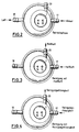
- 2 to 4 are the different phases the use of the feed device according to the invention represented schematically by the corresponding Parts of the flowing media air and water in the operating phase, in which either one or other medium or both media at the same time can be supplied.
- Cleaning liquid for Cleaning the water piping system including Water chamber 40 and water supply channel 25, as well as hot air for blowing dry and disinfecting of the water piping system including the water chamber 40 and water supply channel 25 by means of arrows are indicated. That remains after blowing dry Hermetically sealed water pipe system, so that no new germs can enter through water or more moisture can form from the outside.
- FIG. 5 shows in particular that in the partition wall 42 of the nozzle housing 23 a transition valve designed as a check valve 43 is provided, which is only in the direction of flow from the air chamber 39 to the water chamber 40 opens if there is overpressure on the air chamber side prevails.
- the check valve 43rd because of the larger one prevailing in the water chamber 40 Pressure closed.
- the water chamber 40 beforehand Water, so that in this case the transition valve 43 under the low pressure of the compressed air can open.
- the transition valve 43 is closed anyway.
- the transition valve 43 opens and the hot air can flow through the two Chambers 39, 40 from the water inlet connection 17 come out and blow dry and disinfect of the water piping system can be used. If, as in the case shown, the possibility of cleaning of the water piping system by means of cleaning liquid should be dispensed with, 1 provided water outlet connection 20 omitted.
- the water valve body 2 is essentially the same Way as the air valve body 14 one Restoring force by means of a helical Compression spring 10 exposed on the second rod-shaped connecting member 3 sits. It is also second power transmission element 8, similar to that first power transmission element 11 cap-like on the Housing section 41 interchangeably mounted, see above that the fastening cap 9 according to FIG. 1 is omitted.
- the air outlet opening 16 of the nozzle cap 1 has 8 an approximately U-shaped on the nozzle housing side Cross-sectional shape, which is the air inlet cross-section covered in the end wall 27 of the nozzle housing 23.
- the cross section of the air outlet opening is on the side of the tub 16 in two slot-shaped channel sections.
Landscapes
- Health & Medical Sciences (AREA)
- Public Health (AREA)
- Epidemiology (AREA)
- Pain & Pain Management (AREA)
- Physical Education & Sports Medicine (AREA)
- Rehabilitation Therapy (AREA)
- Life Sciences & Earth Sciences (AREA)
- Animal Behavior & Ethology (AREA)
- General Health & Medical Sciences (AREA)
- Veterinary Medicine (AREA)
- Percussion Or Vibration Massage (AREA)
Description
- Fig.1
- schematisch im Schnitt eine Ausgestaltung der erfindungsgemäßen Wanne im Bereich der Zuführungseinrichtung, die jedoch nicht die Einzelheiten der Erfindung wierdergibt
- Fig. 2 bis 4
- in Draufsicht die Zuführungseinrichtung nach Fig. 1 zur Veranschaulichung verschiedener Anwendungsphasen,
- Fig. 5
- eine Schnittdarstellung entsprechend Fig. 1 für ein anderes Ausführungsbeispiel der Erfindung,
- Fg. 6 u. 7
- in Draufsicht die Zuführungseinrichtung nach Fig. 5 zur Veranschaulichung zweier verschiedener Anwendungsphasen, und
- Fig. 8
- eine erfindungsgemäße Düsensichtplatte von unten gesehen.
- 1
- Sichtkappe
- 2
- Wasserventilkörper
- 3
- zweites Verbindungsorgan
- 4
- vorderer Gehäuseabschnitt des Düsengehäuses
- 5
- Montageklammer
- 6
- Abdichtbuchse
- 7
- hinterer Gehäuseabschnitt des Düsengehäuses
- 8
- zweites Kraftübertragungselement
- 9
- Befestigungskappe
- 10
- zweite Rückstellfeder
- 11
- erstes Kraftübertragungselement
- 12
- erste Rückstellfeder
- 13
- erstes Verbindungsorgan
- 14
- Luftventilkörper
- 15
- Wasseraustrittsöffnung
- 16
- Luftaustrittsöffnung
- 17
- Wasserzutrittsanschluß
- 18
- Luftzutrittsanschluß
- 19
- Öffnung
- 20
- Wasseraustrittsanschluß
- 21
- Luftaustrittsdüse
- 22
- Wasseraustrittsdüse
- 23
- Düsengehäuse
- 24
- Luftzufuhrkanal
- 25
- Wasserzufuhrkanal
- 26
- Wanneninnenraum
- 27
- Stirnwand
- 28
- Luftventilsitz
- 29
- erste Betätigungseinrichtung
- 30
- erste Druckbeaufschlagungsfläche
- 31
- erste rückwärtige Fläche
- 32
- Wasserventilsitz
- 33
- zweite Betätigungseinrichtung
- 34
- zweite Druckbeaufschlagungsfläche
- 35
- zweite rückwärtige Fläche
- 36
- Schiebeabschnitt
- 37
- Aussparung
- 38
- Schließabschnitt
- 39
- Luftkammer
- 40
- Wasserkammer
- 41
- Gehäuseabschnitt
- 42
- Unterteilungswand
- 43
- Übergangsventil
- 44
- Außengewinde
- 45
- Gegenmutter
- 46
- Umfangsflansch
- 47
- Schließabschnitt
- 48
- Schulter
- 49
- Schulter
- 50
- Schiebeabschnitt
- 51
- Umfangswulst
- 52
- Ausbuchtung
- 53
- Ausbuchtung
- 54
- Arretierungsvorsprünge
- 55
- Schulter
Claims (28)
- Wanne, insbesondere Sanitärwanne, mit einer eine Luftaustrittsdüse (21) und eine Wasseraustrittsdüse (22) bildenden Zuführungseinrichtung zum Erzeugen eines Luftsprudels oder/und eines Wassersprudels in dem Wannenwasser, mit einem Düsengehäuse (23), welches Kanäle (24, 25) für die Zufuhr von Wasser bzw. Luft aufweist, wobei der Luftzufuhrkanal (24) und der Wasserzufuhrkanal (25) in zwei eigenen Austrittsöffnungen (15, 16) direkt in den Wanneninnenraum (26) münden und diese je für sich schließbar und öffenbar sind, wobei das Düsengehäuse (23) in eine Luftkammer (39) und eine Wasserkammer (40) unterteilt ist, und wobei in einer Unterteilungswand (42) zwischen Luftkammer (39) und Wasserkammer (40) ein Übergangsventil (43) vorgesehen ist, welches nur in Richtung der Wasserkammer (40) öffnet.
- Wanne nach Anspruch 1, dadurch gekennzeichnet, daß die beiden Austrittsöffnungen (15, 16) unmittelbar nebeneinander in einer Stirnwand (27) und/oder einer stirnseitigen Sichtkappe (1) des Düsengehäuses (23) vorgesehen sind.
- Wanne nach Anspruch 1 oder 2, dadurch gekennzeichnet, daß die Luftaustrittsdüse (21) ein dicht abschließendes Luftventil aufweist, welches unter dem Druck der Luftzufuhr zum Wanneninnenraum (26) gegen die Wirkung einer Rückstellkraft öffenbar ist.
- Wanne nach Anspruch 3, dadurch gekennzeichnet, daß das Luftventil einen Luftventilkörper (14) aufweist, welcher zur Öffnung gegen die Strömungsrichtung der Druckluft in den Wanneninnenraum (26) von dem Luftventilsitz (28) abhebt.
- Wanne nach Anspruch 4, dadurch gekennzeichnet, daß die Druckluft über eine erste Betätigungseinrichtung (29) auf den Luftventilkörper (14) in eine Richtung einwirkt, welche der Strömungsrichtung der Druckluft (26) entgegengerichtet ist
- Wanne nach Anspruch 5, dadurch gekennzeichnet. daß die erste Betätigungseinrichtung (29) eine erste Druckbeaufschlagungsfläche (30) aufweist, welche um ein Vielfaches größer ist als die von der Druckluft in Schließrichtung des Luftventilkörpers (15) unmittelbar beaufschlagte erste rückwärtige Räche (31) des Luftventilkörpers (14).
- Wanne nach Anspruch 5 oder 6, dadurch gekennzeichnet, daß die erste Betätigungseinrichtung (29) ein unter dem Druck der Druckluft ausweichendes balg-, membran- oder kolbenförmiges erstes Kraftübertragungselement (11) aufweist, mit welchem der Luftventilkörper (14) über ein z.B. stangenförmiges erstes Verbindungsorgan (13) kraftschlüssig in Verbindung steht.
- Wanne nach Anspruch 7 , dadurch gekennzeichnet, daß das erste Kraftübertragungselement (11) auf den Luftventilkörper (14) eine Rückstellkraft in Schließrichtung ausübt.
- Wanne nach einem der Ansprüche 4 bis 8, dadurch gekennzeichnet, daß die dem Wanneninnenraum (26) zugeordnete Stirnfläche des Luftventilkörpers (14) in dessen Schließstellung mit der benachbarten Stirnfläche der Stirnwand (27) bzw. der stirnseitigen Sichtkappe (1) des Düsengehäuses (23) fluchtet bzw. dieses geringfügig überragt.
- Wanne nach einem der Ansprüche 1 bis 9, dadurch gekennzeichnet, daß die Wasseraustrittsdüse (22) ein dicht abschließendes Wasserventil aufweist, welches unter dem Druck der Wasserzufuhr zum Wanneninnenraum (26) gegen die Wirkung einer Rückstellkraft öffenbar ist.
- Wanne nach Anspruch 10, dadurch gekennzeichnet, daß das Wasserventil einen Wasserventilkörper (2) aufweist, welcher zur Öffnung gegen die Strömungsrichtung des Druckwassers in den Wanneninnenraum (26) von dem Wasserventilsitz (32) abhebt.
- Wanne nach Anspruch 10 oder 11, dadurch gekennzeichnet, daß das Druckwasser über eine zweite Betätigungseinrichtung (33) auf den Wasserventilkörper (2) in eine Richtung einwirkt, welche der Strömungsrichtung des Druckwassers in den Wanneninnenraum (26) entgegengerichtet ist.
- Wanne nach Anspruch 12, dadurch gekennzeichnet, daß die zweite Betätigungseinrichtung (33) eine zweite Druckbeaufschlagungsfläche (34) aufweist, welche wesentlich, das heißt um ein Vielfaches größer ist als die von dem Druckwasser in Schließrichtung des Wasserventilkörpers (2) unmittelbar beaufschlagte zweite rückwärtige Fläche (35) des Wasserventilkörpers (2) ist.
- Wanne nach Anspruch 12 oder 13, dadurch gekennzeichnet, das die zweite Betätigungseinrichtung (33) ein unter dem Druck des Druckwassers aufweisendes balg-, membran- oder kelbenförmiges zweites Kraftübertragungselement (8) aufweist, mit welchem der Wasserventilkörper (2) über ein z.B. stangenförmiges zweites Verbindungsorgan (3) kraftschlüssig in Verbindung steht.
- Wanne nach Anspruch 14, dadurch gekennzeichnet, daß das zweite Kraftübertragungselement (8) auf den Wasserventilkörper (2) eine Rückstellkraft in Schließrichtung ausübt, indem es beispielsweise als ein federelastisches Element ausgebildet ist.
- Wanne nach Anspruch 14 oder 15, dadurch gekennzeichnet, daß die Rückstellkraft von einer zweiten Rückstellfeder (10) ausgeübt wird, welche auf die der zweiten Druckbeaufschlagungsfläche (34) des zweiten Kraftübertragungselementes (8) gegenüberliegende Seite des Kraftübertragungselements (8) einwirkt
- Wanne nach einem der Ansprüche 11 bis 16, dadurch gekennzeichnet, daß die dem Wanneninnenraum (26) zugekehrte Stirnfläche des Wasserventilkörpers (2) in dessen Schließstellung mit der benachbarten Stirnfläche der Stirnwand (27) bzw. der stirnseitigen Sichtkappe (1) des Düsengehäuses (23) fluchtet bzw. diese geringfügig überragt.
- Wanne nach einem der Ansprüche 11 bis 17, dadurch gekennzeichnet, daß der Wasserventilkörper (2) einen vorderen Schiebeabschnitt (36) aufweist, welcher spielfrei in der Wasseraustrittsöffnung (15) der Stirnwand (27) bzw. der stirnseitigen Sichtkappe (1) des Düsengehäuses (23) geführt ist.
- Wanne nach einem der Ansprüche 11 bis 18. dadurch gekennzeichnet, daß der Wasserventilkörper (2) einen hinteren konischen Schließabschnitt (38) aufweist, welcher mit einem komplementär konisch ausgebildeten Wasserventilsitz (32) zusammenwirkt.
- Wanne nach einem der Ansprüche 4 bis 19, dadurch gekennzeichnet, daß der Luftventilkörper (14) und/oder der Wasserventilkörper (2) aus flexiblem Material, wie Gummi oder Kunststoff, bestehen bzw. besteht.
- Wanne nach einem der Ansprüche 1 bis 20, dadurch gekennzeichnet, daß das Düsengehäuse (23) an seinem rückwärtigen Ende von dem vorzugsweise kappenartig ausgebildeten austauschbar lösbar gehaltenen ersten Kraftübertragungselement (11) abgeschlossen ist.
- Wanne nach einem der Ansprüche 14 bis 21, dadurch gekennzeichnet, daß das zweite Kraftübertragungselement (8) mittels einer Befestigungskappe (19) an einem Gehäuseabschnitt (41) lösbar austauschbar gehalten ist.
- Wanne nach Anspruch 1 oder 22, dadurch gekennzeichnet, daß der das zweite Kraftübertragungselement (8) aufweisende Teil der Wasserkammer (40) innerhalb der Luftkammer (39) angeordnet ist.
- Wanne nach einem der Ansprüche 1 bis 23, dadurch gekennzeichnet, daß in die Luftkammer (39) ein Luftzutrittsanschluß (18) und in die Wasserkammer (40) ein Wasserzutrittsanschluß (17) mündet.
- Wanne nach einem der Ansprüche 1 bis 24, dadurch gekennzeichnet, daß an der Wasserkammer (40) ein Wasseraustrittsanschluß (20) vorgesehen ist.
- Wanne nach einen der Ansprüch 1 bis 25, dadurch gekennzeichnet, daß das Übergangsventil (23) als Rückschlagventil ausgebildet ist.
- Wanne nach einem der Ansprüche 1 bis 26, dadurch gekennzeichnet daß das Düsengehäuse (23) in einen vorderen Abschnitt (4) und einen hinteren, z.B. kammerartig erweiterten Abschnitt (7) unterteilt ist, und daß die Abschnitte (4, 7) z.B. mittels einer Montageklammer (5) lösbar zusammengehalten sind.
- Wanne nach einem der Ansprüche 1 bis 27, dadurch gekennzeichnet, daß die Sichtkappe (1) Austrittsöffnungen (15, 16) für Wasser und Luft aufweist, deren dem Düsengehäuse (23) zugewandter Querschnitt den Austrittsquerschnitt des Wasser-bzw. Luftzufuhrkanals (25, 24) überdeckt und deren dem Wanneninnenraum (26) zugewandter Querschnitt eine davon abweichende Kontur (z.B. schlitzförmig für Luft) oder Austrittsrichtung (z.B. schräggestellt für Wasser) hat.
Applications Claiming Priority (2)
| Application Number | Priority Date | Filing Date | Title |
|---|---|---|---|
| DE4306785 | 1993-03-04 | ||
| DE4306785A DE4306785C2 (de) | 1993-03-04 | 1993-03-04 | Wanne, insbesondere Sanitärwanne, mit Sprudeleinrichtung |
Publications (3)
| Publication Number | Publication Date |
|---|---|
| EP0613673A1 EP0613673A1 (de) | 1994-09-07 |
| EP0613673B1 EP0613673B1 (de) | 1996-08-21 |
| EP0613673B2 true EP0613673B2 (de) | 2002-01-02 |
Family
ID=6481936
Family Applications (1)
| Application Number | Title | Priority Date | Filing Date |
|---|---|---|---|
| EP93120649A Expired - Lifetime EP0613673B2 (de) | 1993-03-04 | 1993-12-22 | Austrittsdüse für Badewanne zum Erzeugen eines Luft- und/oder eines Wassersprudels |
Country Status (3)
| Country | Link |
|---|---|
| EP (1) | EP0613673B2 (de) |
| DE (2) | DE4306785C2 (de) |
| ES (1) | ES2093351T5 (de) |
Families Citing this family (5)
| Publication number | Priority date | Publication date | Assignee | Title |
|---|---|---|---|---|
| NL1005235C2 (nl) * | 1997-02-10 | 1998-08-11 | Sanilux Bv | Whirlpool-injector en whirlpool-systeem. |
| AT405659B (de) * | 1998-01-20 | 1999-10-25 | Koller Rudolf | Düsenarmatur für wannen oder becken für sprudelbäder |
| EP1022011B1 (de) | 1999-01-22 | 2004-11-10 | Rudolf Koller | Düsenarmatur für Wannen oder Becken für Sprudelbäder |
| DK1226805T3 (da) * | 2001-01-26 | 2003-01-20 | Kaldewei Franz Gmbh & Co | Anordning til frembringelse af et boblebad i et sanitetskar |
| AT521267B1 (de) | 2018-10-02 | 2019-12-15 | Kantor Georg | Whirlpooldüse |
Citations (5)
| Publication number | Priority date | Publication date | Assignee | Title |
|---|---|---|---|---|
| WO1988001858A1 (fr) † | 1986-09-10 | 1988-03-24 | Schuessler Guenter | Buse d'hydromassage generatrice de bouillonnements dans un bassin d'eau |
| DE3790555C1 (de) † | 1986-09-10 | 1991-10-24 | Guenter Schuessler | Hydro-Massageduese zur Erzeugung eines Luftsprudels in einem Wasserbecken |
| EP0268050B1 (de) † | 1986-10-17 | 1991-11-06 | Ucosan B.V. | Reinigungseinrichtung für das Rohrleitungssystem einer Whirlpool-Wanne sowie Austrittsventil für Whirlpool-Wanne |
| DE4108364A1 (de) † | 1991-03-15 | 1992-09-17 | Ucosan Bv | Wanne, insbesondere sanitaerwanne, mit luftsprudeleinrichtung |
| EP0311967B1 (de) † | 1987-10-12 | 1994-01-05 | Jacuzzi Europe Spa | Hydromassage-Armatur mit automatischer Schliessvorrichtung |
Family Cites Families (1)
| Publication number | Priority date | Publication date | Assignee | Title |
|---|---|---|---|---|
| IT1249269B (it) * | 1991-05-24 | 1995-02-21 | Sea Di Filipponi A E C S N C | Bocchetta per idromassaggio |
-
1993
- 1993-03-04 DE DE4306785A patent/DE4306785C2/de not_active Expired - Fee Related
- 1993-12-22 EP EP93120649A patent/EP0613673B2/de not_active Expired - Lifetime
- 1993-12-22 DE DE59303505T patent/DE59303505D1/de not_active Expired - Fee Related
- 1993-12-22 ES ES93120649T patent/ES2093351T5/es not_active Expired - Lifetime
Patent Citations (5)
| Publication number | Priority date | Publication date | Assignee | Title |
|---|---|---|---|---|
| WO1988001858A1 (fr) † | 1986-09-10 | 1988-03-24 | Schuessler Guenter | Buse d'hydromassage generatrice de bouillonnements dans un bassin d'eau |
| DE3790555C1 (de) † | 1986-09-10 | 1991-10-24 | Guenter Schuessler | Hydro-Massageduese zur Erzeugung eines Luftsprudels in einem Wasserbecken |
| EP0268050B1 (de) † | 1986-10-17 | 1991-11-06 | Ucosan B.V. | Reinigungseinrichtung für das Rohrleitungssystem einer Whirlpool-Wanne sowie Austrittsventil für Whirlpool-Wanne |
| EP0311967B1 (de) † | 1987-10-12 | 1994-01-05 | Jacuzzi Europe Spa | Hydromassage-Armatur mit automatischer Schliessvorrichtung |
| DE4108364A1 (de) † | 1991-03-15 | 1992-09-17 | Ucosan Bv | Wanne, insbesondere sanitaerwanne, mit luftsprudeleinrichtung |
Non-Patent Citations (1)
| Title |
|---|
| Prospekt "Aqua & Air" UV096.05.91, Ucosan-Sanitrend GmbH † |
Also Published As
| Publication number | Publication date |
|---|---|
| EP0613673B1 (de) | 1996-08-21 |
| ES2093351T5 (es) | 2002-04-01 |
| ES2093351T3 (es) | 1996-12-16 |
| EP0613673A1 (de) | 1994-09-07 |
| DE59303505D1 (de) | 1996-09-26 |
| DE4306785C2 (de) | 2000-08-03 |
| DE4306785A1 (de) | 1994-09-08 |
Similar Documents
| Publication | Publication Date | Title |
|---|---|---|
| DE3447772A1 (de) | Verfahren und vorrichtung zum desinfizieren des umlaufsystems einer whirlpool-badewanne | |
| DE2852265A1 (de) | Massagedusche mit einer fuehrungsschiene | |
| EP0354596A2 (de) | Vorrichtung zur Verbesserung einer Whirlpoolwanne | |
| DE102016213491A1 (de) | Brausestrahlerzeugungsvorrichtung | |
| DE2325260A1 (de) | Sanitaer-hygienische vorrichtung | |
| EP0613673B1 (de) | Austrittsdüse für Badewanne zum Erzeugen eines Luft- und/oder eines Wassersprudels | |
| EP3933127B1 (de) | Stromloser dusch-wc-aufsatz mit einer selbstreinigungsvorrichtung und selbstreinigungsverfahren für einen stromlosen dusch-wc-aufsatz | |
| DE3824834C2 (de) | ||
| EP0503239B1 (de) | Wanne, insbesondere Sanitärwanne, mit Luftsprudeleinrichtung | |
| DE69431863T2 (de) | Hydromassagegewanne mit Rotationsverteiler | |
| DE20317910U1 (de) | Strahlregler für einen Auslauf einer wasserführenden Armatur | |
| DE2729198C2 (de) | Vorrichtung zur Regelung der Luftzufuhr bei Luftsprudelmatten in Luftsprudelmassagebädern | |
| DE102019220176B3 (de) | Brausekopf mit kammerbegrenzender Elastomermatte | |
| AT400868B (de) | Sanitärarmatur | |
| EP2479138A2 (de) | Vorrichtung zum Zapfen einer Flüssigkeit | |
| DE4010976C1 (de) | ||
| DE3636328A1 (de) | Vorrichtung zum einbau in das abflusssystem von badewannen und dgl. mit whirlpool-einrichtung | |
| DE3779620T2 (de) | Wasser- und/oder luft-einspritzduese fuer eine badewanne einer balneotherapie-einrichtung. | |
| DE102017004912B4 (de) | Vorrichtung zur Desinfektion und/oder Entkalkung insbesondere von Duschköpfen | |
| EP2301668B1 (de) | Brause mit drehbarem Brausekopf | |
| DE3139981A1 (de) | Fluiddispenser in aufrechter gebrauchslage | |
| DE69007818T2 (de) | Whirlpool-Wanne mit Luftdüsen. | |
| DE19713381C1 (de) | Massagegerät | |
| WO2021259451A1 (de) | Pflegebürste mit einem pflegemittelbehälter | |
| DE2536569A1 (de) | Vorrichtung zur erzeugung einer gegenstroemung in schwimmbecken |
Legal Events
| Date | Code | Title | Description |
|---|---|---|---|
| PUAI | Public reference made under article 153(3) epc to a published international application that has entered the european phase |
Free format text: ORIGINAL CODE: 0009012 |
|
| AK | Designated contracting states |
Kind code of ref document: A1 Designated state(s): DE ES FR GB IT NL |
|
| 17P | Request for examination filed |
Effective date: 19941012 |
|
| GRAG | Despatch of communication of intention to grant |
Free format text: ORIGINAL CODE: EPIDOS AGRA |
|
| GRAH | Despatch of communication of intention to grant a patent |
Free format text: ORIGINAL CODE: EPIDOS IGRA |
|
| 17Q | First examination report despatched |
Effective date: 19960110 |
|
| GRAH | Despatch of communication of intention to grant a patent |
Free format text: ORIGINAL CODE: EPIDOS IGRA |
|
| GRAA | (expected) grant |
Free format text: ORIGINAL CODE: 0009210 |
|
| AK | Designated contracting states |
Kind code of ref document: B1 Designated state(s): DE ES FR GB IT NL |
|
| REF | Corresponds to: |
Ref document number: 59303505 Country of ref document: DE Date of ref document: 19960926 |
|
| ITF | It: translation for a ep patent filed | ||
| GBT | Gb: translation of ep patent filed (gb section 77(6)(a)/1977) |
Effective date: 19961104 |
|
| ET | Fr: translation filed | ||
| REG | Reference to a national code |
Ref country code: ES Ref legal event code: FG2A Ref document number: 2093351 Country of ref document: ES Kind code of ref document: T3 |
|
| PLBI | Opposition filed |
Free format text: ORIGINAL CODE: 0009260 |
|
| 26 | Opposition filed |
Opponent name: SCHUESSLER GUENTER Effective date: 19970401 |
|
| PLBF | Reply of patent proprietor to notice(s) of opposition |
Free format text: ORIGINAL CODE: EPIDOS OBSO |
|
| NLR1 | Nl: opposition has been filed with the epo |
Opponent name: SCHUESSLER GUENTER |
|
| PLBF | Reply of patent proprietor to notice(s) of opposition |
Free format text: ORIGINAL CODE: EPIDOS OBSO |
|
| PLBO | Opposition rejected |
Free format text: ORIGINAL CODE: EPIDOS REJO |
|
| APAC | Appeal dossier modified |
Free format text: ORIGINAL CODE: EPIDOS NOAPO |
|
| APAE | Appeal reference modified |
Free format text: ORIGINAL CODE: EPIDOS REFNO |
|
| APAC | Appeal dossier modified |
Free format text: ORIGINAL CODE: EPIDOS NOAPO |
|
| PLBQ | Unpublished change to opponent data |
Free format text: ORIGINAL CODE: EPIDOS OPPO |
|
| PLAB | Opposition data, opponent's data or that of the opponent's representative modified |
Free format text: ORIGINAL CODE: 0009299OPPO |
|
| R26 | Opposition filed (corrected) |
Opponent name: SCHUESSLER GUENTER Effective date: 19970401 |
|
| NLR1 | Nl: opposition has been filed with the epo |
Opponent name: SCHUESSLER GUENTER |
|
| APAC | Appeal dossier modified |
Free format text: ORIGINAL CODE: EPIDOS NOAPO |
|
| PLAW | Interlocutory decision in opposition |
Free format text: ORIGINAL CODE: EPIDOS IDOP |
|
| PUAH | Patent maintained in amended form |
Free format text: ORIGINAL CODE: 0009272 |
|
| STAA | Information on the status of an ep patent application or granted ep patent |
Free format text: STATUS: PATENT MAINTAINED AS AMENDED |
|
| REG | Reference to a national code |
Ref country code: GB Ref legal event code: IF02 |
|
| 27A | Patent maintained in amended form |
Effective date: 20020102 |
|
| AK | Designated contracting states |
Kind code of ref document: B2 Designated state(s): DE ES FR GB IT NL |
|
| GBTA | Gb: translation of amended ep patent filed (gb section 77(6)(b)/1977) | ||
| NLR2 | Nl: decision of opposition | ||
| REG | Reference to a national code |
Ref country code: ES Ref legal event code: DC2A Kind code of ref document: T5 Effective date: 20020111 |
|
| NLR3 | Nl: receipt of modified translations in the netherlands language after an opposition procedure | ||
| ET3 | Fr: translation filed ** decision concerning opposition | ||
| NLR3 | Nl: receipt of modified translations in the netherlands language after an opposition procedure | ||
| PGFP | Annual fee paid to national office [announced via postgrant information from national office to epo] |
Ref country code: GB Payment date: 20031201 Year of fee payment: 11 |
|
| PGFP | Annual fee paid to national office [announced via postgrant information from national office to epo] |
Ref country code: NL Payment date: 20031217 Year of fee payment: 11 |
|
| PGFP | Annual fee paid to national office [announced via postgrant information from national office to epo] |
Ref country code: FR Payment date: 20031218 Year of fee payment: 11 |
|
| PGFP | Annual fee paid to national office [announced via postgrant information from national office to epo] |
Ref country code: ES Payment date: 20031222 Year of fee payment: 11 |
|
| PG25 | Lapsed in a contracting state [announced via postgrant information from national office to epo] |
Ref country code: GB Free format text: LAPSE BECAUSE OF NON-PAYMENT OF DUE FEES Effective date: 20041222 |
|
| PG25 | Lapsed in a contracting state [announced via postgrant information from national office to epo] |
Ref country code: ES Free format text: LAPSE BECAUSE OF NON-PAYMENT OF DUE FEES Effective date: 20041223 |
|
| PG25 | Lapsed in a contracting state [announced via postgrant information from national office to epo] |
Ref country code: NL Free format text: LAPSE BECAUSE OF NON-PAYMENT OF DUE FEES Effective date: 20050701 |
|
| GBPC | Gb: european patent ceased through non-payment of renewal fee |
Effective date: 20041222 |
|
| PG25 | Lapsed in a contracting state [announced via postgrant information from national office to epo] |
Ref country code: FR Free format text: LAPSE BECAUSE OF NON-PAYMENT OF DUE FEES Effective date: 20050831 |
|
| NLV4 | Nl: lapsed or anulled due to non-payment of the annual fee |
Effective date: 20050701 |
|
| APAH | Appeal reference modified |
Free format text: ORIGINAL CODE: EPIDOSCREFNO |
|
| REG | Reference to a national code |
Ref country code: FR Ref legal event code: ST |
|
| PG25 | Lapsed in a contracting state [announced via postgrant information from national office to epo] |
Ref country code: IT Free format text: LAPSE BECAUSE OF NON-PAYMENT OF DUE FEES Effective date: 20051222 |
|
| REG | Reference to a national code |
Ref country code: ES Ref legal event code: FD2A Effective date: 20041223 |
|
| PGFP | Annual fee paid to national office [announced via postgrant information from national office to epo] |
Ref country code: DE Payment date: 20080221 Year of fee payment: 15 |
|
| PG25 | Lapsed in a contracting state [announced via postgrant information from national office to epo] |
Ref country code: DE Free format text: LAPSE BECAUSE OF NON-PAYMENT OF DUE FEES Effective date: 20090701 |