EP0586876A1 - Dispositif pour la séparation controlée de déchets à partir d'un matériau imprimé - Google Patents
Dispositif pour la séparation controlée de déchets à partir d'un matériau imprimé Download PDFInfo
- Publication number
- EP0586876A1 EP0586876A1 EP93112461A EP93112461A EP0586876A1 EP 0586876 A1 EP0586876 A1 EP 0586876A1 EP 93112461 A EP93112461 A EP 93112461A EP 93112461 A EP93112461 A EP 93112461A EP 0586876 A1 EP0586876 A1 EP 0586876A1
- Authority
- EP
- European Patent Office
- Prior art keywords
- cylinder
- waste
- printing materials
- materials according
- knives
- Prior art date
- Legal status (The legal status is an assumption and is not a legal conclusion. Google has not performed a legal analysis and makes no representation as to the accuracy of the status listed.)
- Granted
Links
Images


Classifications
-
- B—PERFORMING OPERATIONS; TRANSPORTING
- B26—HAND CUTTING TOOLS; CUTTING; SEVERING
- B26D—CUTTING; DETAILS COMMON TO MACHINES FOR PERFORATING, PUNCHING, CUTTING-OUT, STAMPING-OUT OR SEVERING
- B26D7/00—Details of apparatus for cutting, cutting-out, stamping-out, punching, perforating, or severing by means other than cutting
- B26D7/26—Means for mounting or adjusting the cutting member; Means for adjusting the stroke of the cutting member
- B26D7/2628—Means for adjusting the position of the cutting member
- B26D7/265—Journals, bearings or supports for positioning rollers or cylinders relatively to each other
-
- B—PERFORMING OPERATIONS; TRANSPORTING
- B26—HAND CUTTING TOOLS; CUTTING; SEVERING
- B26D—CUTTING; DETAILS COMMON TO MACHINES FOR PERFORATING, PUNCHING, CUTTING-OUT, STAMPING-OUT OR SEVERING
- B26D7/00—Details of apparatus for cutting, cutting-out, stamping-out, punching, perforating, or severing by means other than cutting
- B26D7/18—Means for removing cut-out material or waste
- B26D7/1845—Means for removing cut-out material or waste by non mechanical means
- B26D7/1854—Means for removing cut-out material or waste by non mechanical means by air under pressure
-
- B—PERFORMING OPERATIONS; TRANSPORTING
- B26—HAND CUTTING TOOLS; CUTTING; SEVERING
- B26D—CUTTING; DETAILS COMMON TO MACHINES FOR PERFORATING, PUNCHING, CUTTING-OUT, STAMPING-OUT OR SEVERING
- B26D7/00—Details of apparatus for cutting, cutting-out, stamping-out, punching, perforating, or severing by means other than cutting
- B26D7/18—Means for removing cut-out material or waste
- B26D7/1845—Means for removing cut-out material or waste by non mechanical means
- B26D7/1863—Means for removing cut-out material or waste by non mechanical means by suction
-
- B—PERFORMING OPERATIONS; TRANSPORTING
- B26—HAND CUTTING TOOLS; CUTTING; SEVERING
- B26D—CUTTING; DETAILS COMMON TO MACHINES FOR PERFORATING, PUNCHING, CUTTING-OUT, STAMPING-OUT OR SEVERING
- B26D7/00—Details of apparatus for cutting, cutting-out, stamping-out, punching, perforating, or severing by means other than cutting
- B26D7/26—Means for mounting or adjusting the cutting member; Means for adjusting the stroke of the cutting member
- B26D7/2614—Means for mounting the cutting member
-
- B—PERFORMING OPERATIONS; TRANSPORTING
- B41—PRINTING; LINING MACHINES; TYPEWRITERS; STAMPS
- B41F—PRINTING MACHINES OR PRESSES
- B41F13/00—Common details of rotary presses or machines
- B41F13/54—Auxiliary folding, cutting, collecting or depositing of sheets or webs
- B41F13/56—Folding or cutting
- B41F13/62—Folding-cylinders or drums
-
- Y—GENERAL TAGGING OF NEW TECHNOLOGICAL DEVELOPMENTS; GENERAL TAGGING OF CROSS-SECTIONAL TECHNOLOGIES SPANNING OVER SEVERAL SECTIONS OF THE IPC; TECHNICAL SUBJECTS COVERED BY FORMER USPC CROSS-REFERENCE ART COLLECTIONS [XRACs] AND DIGESTS
- Y10—TECHNICAL SUBJECTS COVERED BY FORMER USPC
- Y10T—TECHNICAL SUBJECTS COVERED BY FORMER US CLASSIFICATION
- Y10T83/00—Cutting
- Y10T83/202—With product handling means
- Y10T83/2066—By fluid current
- Y10T83/207—By suction means
-
- Y—GENERAL TAGGING OF NEW TECHNOLOGICAL DEVELOPMENTS; GENERAL TAGGING OF CROSS-SECTIONAL TECHNOLOGIES SPANNING OVER SEVERAL SECTIONS OF THE IPC; TECHNICAL SUBJECTS COVERED BY FORMER USPC CROSS-REFERENCE ART COLLECTIONS [XRACs] AND DIGESTS
- Y10—TECHNICAL SUBJECTS COVERED BY FORMER USPC
- Y10T—TECHNICAL SUBJECTS COVERED BY FORMER US CLASSIFICATION
- Y10T83/00—Cutting
- Y10T83/202—With product handling means
- Y10T83/2092—Means to move, guide, or permit free fall or flight of product
- Y10T83/2183—Product mover including gripper means
- Y10T83/2185—Suction gripper
-
- Y—GENERAL TAGGING OF NEW TECHNOLOGICAL DEVELOPMENTS; GENERAL TAGGING OF CROSS-SECTIONAL TECHNOLOGIES SPANNING OVER SEVERAL SECTIONS OF THE IPC; TECHNICAL SUBJECTS COVERED BY FORMER USPC CROSS-REFERENCE ART COLLECTIONS [XRACs] AND DIGESTS
- Y10—TECHNICAL SUBJECTS COVERED BY FORMER USPC
- Y10T—TECHNICAL SUBJECTS COVERED BY FORMER US CLASSIFICATION
- Y10T83/00—Cutting
- Y10T83/465—Cutting motion of tool has component in direction of moving work
- Y10T83/4766—Orbital motion of cutting blade
- Y10T83/4795—Rotary tool
Definitions
- the invention relates to a device for the controlled removal of waste pieces of printing materials, in particular on a cutting cylinder.
- DE-PS 1 19 48 75 discloses an apparatus for the appropriate feeding of paper sheets to a blank processing machine.
- the suction element designed as a suction drum comprises a chamber that is permanently under suction and a second suction chamber that can be controlled under suction.
- the suction air is applied to the front of the suction drum.
- the jacket broken through the individual bores rotates together with the drum; Blowing air is not provided on the jacket of the drum.
- US 4,407,870 finally shows a cutting device for the continuous cutting and removal of thin strips of a printed web.
- the strip which is separated from a pair of knives working together with a lower knife, is sucked in by negative pressure and reaches a central bore of the cutting cylinder, from which it is subsequently removed.
- a disadvantage of this device is the fact that it requires a large negative pressure volume in order to convey the strip into the interior of the cylinder. Furthermore, this device has limits with regard to the peripheral speed, since the centrifugal forces which occur at high peripheral speeds and act on the strip must be additionally compensated for by the vacuum in the channel. The conveying paths to the inside of the cutting cylinder are too long for high speeds.
- the object of the invention is to reliably detect waste pieces of printing materials during and after the cut, regardless of the specific paper weight, and to keep the air volumes required for this to be small.
- the chambers extend essentially over the length of the cutting cylinder parallel to the cylinder axis. This results in an even application of pressure to the surface of the cylinder jacket both by blown air and with a vacuum for handling waste strips of various substrate thicknesses. Starting with thin, fluttering papers from 40 g / m2 to thicker materials of around 200 g / m2.
- the chambers are delimited by at least one sealing strip which can be fixed in the circumferential direction on the cylinder axis.
- the length of the chambers can be shortened or extended, depending on the requirements.
- the chambers form circular arc-shaped sectors on the cylinder axis in the circumferential direction, which favors a simple and inexpensive blown air supply or vacuum application through bores in the cylinder axis.
- the cylinder axis can be variably fixed in its rotational position by a torque arm. On the one hand, this allows a defined position of the cylinder axis to be defined, which it also maintains during production. On the other hand, sensitive twisting of the cylinder axis can be carried out after loosening the clamping screw on the torque arm. In this way, the chamber position between the cylinder axes and the rotatably mounted cylinder jacket can be adjusted.
- the cylinder jacket is arranged such that it can be driven separately via bearings on the cylinder axis.
- the cylinder jacket on the cylinder axis is driven by a pulley arranged on a cylinder journal.
- This drive configuration allows the rotating cylinder jacket to be used as a switching element for changing the types of air with which the bores on the circumference of the cylinder jacket are applied. Valves or throttles can be dispensed with entirely, since the blown air chamber and the suction air chamber are permanently pressurized and the air changeover is only effected by the rotation of the cylinder jacket on the cylinder axis, which receives the sealing strips for chamber separation.
- the pairs of knives consist of one-piece knives which extend in the axial direction over the entire length of the cylinder jacket. This guarantees an even cut and easier adjustment during the presetting.
- a suction device takes over pieces of waste from the cylinder jacket of the cutting cylinder.
- the suction device supports the takeover of the waste strip expelled from the cylinder jacket by the action of blowing air. Since the centrifugal force also acts on them, there is a safe transfer into the suction device.
- the contour of the blown air chamber in the circumferential direction on the cylinder axis advantageously coincides with the area on the circumference of the cutting cylinder opposite the suction opening of the suction device.
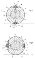
- Fig. 1 an operator-side storage of a cutting cylinder is shown.
- a cutting cylinder 1 consists of a cylinder jacket 2, which is pierced by at least two rows of bores 3 running parallel to the axis and a cylinder axis 4.
- a cylinder journal 5 is connected to the cylinder jacket 2 by screws 6.
- a bearing 7 is fixed in its axial position on the cylinder axis 4 by a locking ring 8 and a spacer ring 9.
- a cone 10 On the cylinder journal 5, a cone 10 is provided, on which a roller bearing 14 is seated, which in turn is fixed in position on the cone 10 by a lock nut 12 and locking plate 11.
- the cylinder jacket 2 is rotatably received in a bushing of the side wall 24 via the cylinder pin 5, the cone 10 and the roller bearing 14, while the cylinder axis 4 passing through the cylinder pin 5 and the cylinder jacket 2 does not rotate.
- the roller bearing 14 Between the area of the cylinder axis 4, which is penetrated by the blowing and suction air bores 20 and 22 (shown here in dashed lines) and the cylinder journal 5, there is therefore no contact.
- the roller bearing 14 On the cylinder side, the roller bearing 14 bears against a ring 13 which is supported on a shoulder of the bearing journal 5.
- the ring 13 or ring 30 in FIG. 2 serving as a seal is enclosed by the cylinder-side bearing housing 15, which is held in a socket in the side wall 24 by means of screws 16.
- the cover 17 is connected to the end face of the cylinder journal 5 by screws.
- the cover 17 is enclosed by a bearing housing 18 which is fastened on the end face in a bushing in the side wall 24. Accordingly, when the cylinder jacket 2 rotates, both the ring 13 and the cover 17 rotate relative to the side-wall-fixed bearing housings 15 and 18, from which they are separated by narrow air gaps.
- a torque support 19 is attached to the side wall 24, which holds the cylinder axis 4 at rest by means of a clamp.
- the torque arm 19 surrounds the cylinder axis 4 in the area in which the connecting pieces for the blown air supply line 21 and the suction air line 23 are located. These each act on the blown air bore 20 or the suction air bore 22, which pass through the cylinder axis 4 approximately to the center of the axis.
- the sectors of an annular chamber 25 between the cylinder axis 4 and the inside of the cylinder jacket 2 are acted upon by blowing or suction air through the blowing air bore 20 or the suction air bore 22.
- the torque arm has the function of keeping the cylinder axis 4 at rest so that its position is not changed by bearing friction.
- the circumferential position of the cylinder axis 4 can be varied by means of the clamping provided on the torque support, which enables the suction and blowing function of the cutting cylinder 1 to be influenced.
- the cylinder jacket 2 is rotatable on the cylinder axis 4 by a bearing 7 arranged on the drive-side end of the cylinder axis 4.
- a cylinder pin 29 is connected to the cylinder jacket 2 by screws 6.
- the cone 10 is fastened, on which a roller bearing 14 is received by the locking plate 11 and the lock nut 12.
- the outer ring of the roller bearing 14 is held in position by the bearing housings 15 and 18, which are each received via screws 16 in the side wall 28 on the drive side.
- a drive wheel 35 initiating the drive and a belt pulley 32 are rotatably mounted on the extension of the cylinder journal 29.
- the drive wheel 35 and the pulley 32 are rotatably received by a key 34.
- the drive wheel 35 and the pulley 32 can be removed after removing a cover 36 from the cylinder journal 29.
- FIG 3 shows a cross section through the cylinder jacket and cylinder axis of a cutting cylinder.
- the cylinder axis 4 is penetrated by a blowing air bore 20 extending axially to approximately the center of the cutting cylinder 1 and a suction air bore 22.
- 4 sealing strips 42 are fastened to the circumference of the cylinder axis by screws, a pressure chamber 27 or a suction chamber 26 being delimited by their position on the circumference of the cylinder axis 4.
- These chambers are circumferentially bounded by the inside of the cylinder jacket 2, which in turn is penetrated by the rows of bores.
- the knives 41 shown here are formed in one piece and can be adjusted by means of adjusting screws 40 such that the positions of the cutting edges of the knives 41 in relation to the outer surface of the cylinder jacket 2 or a machine-fixed lower knife can be adjusted precisely. It would therefore be conceivable to turn these adjusting screws 40 by servomotors provided in the cylinder jacket 2 in order to be able to make this setting.
- Four blades can be formed on the blades 41, which are designed here with a rectangular cross-section, so that the service life of the blades 41 is favorably influenced.
- the rows of bores 3 alternately come into contact with the pressure chamber 27 or with the suction chamber 26, which results in alternating air switching from suction to blown air and vice versa during the rotation of the cylinder jacket 2 .
- the sealing strips 42 By changing the positions of the sealing strips 42, which delimit the chambers 26 and 27, the areas of action of suction and blown air can of course be adapted to individual requirements, furthermore the sealing strips 42 can be provided with resilient underlays in order to achieve a sealing which follows itself .
- FIG. 4 shows the cylinder jacket 2, which is mounted on the cylinder axis 4 and can be driven separately.
- the suction chamber 26 and the pressure chamber 27 are separated from one another by schematically illustrated sealing strips 42.
- the cylinder axis 4 is through a blow air bore 20 and a suction air bore 22, which are permanently acted upon.
- the holes 3 assigned to the pair of knives 37 are connected to the suction chamber 26.
- the suction hood 43 arranged above the cutting cylinder 1 sucks off the waste strip 45, so that it is reliably removed from the cylinder jacket 2.
- the suction hood 43 advantageously extends over a shape and shape corresponding to the pressure chamber 27 Area; this ensures maximum conveying and handling security of the waste strip 45.
- the pair of knives 37 opposite the pair of knives 37 leading the waste strips 45 cuts a waste strip 45 out of the printing material web 44 at the same time.
- the bores 3 of the lower pair of knives 37 are connected to the suction chamber 26 of the cylinder axis 4 and the next material strip 45 to be separated is sucked in.
Landscapes
- Engineering & Computer Science (AREA)
- Mechanical Engineering (AREA)
- Life Sciences & Earth Sciences (AREA)
- Forests & Forestry (AREA)
- Perforating, Stamping-Out Or Severing By Means Other Than Cutting (AREA)
- Paper (AREA)
- Processing And Handling Of Plastics And Other Materials For Molding In General (AREA)
- Details Of Cutting Devices (AREA)
Applications Claiming Priority (2)
| Application Number | Priority Date | Filing Date | Title |
|---|---|---|---|
| DE4229699 | 1992-09-05 | ||
| DE4229699A DE4229699C2 (de) | 1992-09-05 | 1992-09-05 | Vorrichtung zur kontrollierten Beseitigung von Abfall-Stücken von Bedruckstoffen |
Publications (2)
| Publication Number | Publication Date |
|---|---|
| EP0586876A1 true EP0586876A1 (fr) | 1994-03-16 |
| EP0586876B1 EP0586876B1 (fr) | 1996-03-27 |
Family
ID=6467312
Family Applications (1)
| Application Number | Title | Priority Date | Filing Date |
|---|---|---|---|
| EP93112461A Expired - Lifetime EP0586876B1 (fr) | 1992-09-05 | 1993-08-04 | Dispositif pour la séparation controlée de déchets à partir d'un matériau imprimé |
Country Status (6)
| Country | Link |
|---|---|
| US (1) | US5419224A (fr) |
| EP (1) | EP0586876B1 (fr) |
| JP (1) | JPH06170791A (fr) |
| CN (1) | CN1036903C (fr) |
| AT (1) | ATE135948T1 (fr) |
| DE (2) | DE4229699C2 (fr) |
Cited By (2)
| Publication number | Priority date | Publication date | Assignee | Title |
|---|---|---|---|---|
| DE19634628C1 (de) * | 1996-08-27 | 1997-10-23 | Badenia Gmbh | Verfahren und Vorrichtung zum Recyceln von Steppdeckenfüllmaterial |
| US7896329B2 (en) | 2006-06-12 | 2011-03-01 | Heidelberger Druckmaschinen Aktiengesellschaft | Waste blower for a paper sheet punching and embossing machine |
Families Citing this family (24)
| Publication number | Priority date | Publication date | Assignee | Title |
|---|---|---|---|---|
| USRE38033E1 (en) * | 1993-12-22 | 2003-03-18 | Best Cutting Die Company | Panel cutting apparatus |
| DE29503245U1 (de) * | 1995-02-27 | 1995-04-06 | Roland Man Druckmasch | Luftversorgungseinrichtung für eine Rotationsdruckmaschine |
| US5603249A (en) * | 1995-04-19 | 1997-02-18 | R & B Machine Tool Company | Trim cutter apparatus for blow molded articles |
| DE19532027A1 (de) * | 1995-08-31 | 1997-03-06 | Koenig & Bauer Albert Ag | Verfahren und Vorrichtung zum Entfernen von auf Punkturnadeln befindlichen Beschnittstreifen |
| JP2911027B2 (ja) * | 1995-12-28 | 1999-06-23 | 花王株式会社 | ウエブの切断装置及び方法 |
| FR2743523B1 (fr) * | 1996-01-15 | 1998-03-06 | Komori Chambon | Cylindre massif pour machine de faconnage rotative |
| DE19848973A1 (de) * | 1998-10-23 | 2000-04-27 | Bielomatik Leuze & Co | Querschneider für Bahnmaterialien |
| EP1125646B1 (fr) | 2000-02-01 | 2003-08-06 | Heidelberger Druckmaschinen Aktiengesellschaft | Dispositif pour enlever des particules de bandes |
| DE10004305A1 (de) * | 2000-02-01 | 2001-08-02 | Heidelberger Druckmasch Ag | Verfahren und Vorrichtung zur Entfernung von Partikeln von Materialbahnen |
| DE20104247U1 (de) * | 2001-03-12 | 2001-09-06 | Offsetdruck Nuernberg Gmbh & C | Stanzanordnung |
| US20050070415A1 (en) * | 2003-09-30 | 2005-03-31 | Haasl Andrew L. | Assembly for and method of preventing buildup of debris in a folding roll tucker assembly |
| SE528038C2 (sv) * | 2004-07-02 | 2006-08-15 | Sandvik Intellectual Property | En luftdistributionsaggregat och en rotationsknivanordning försedd med ett dylikt lutfdistributionsaggregat |
| SE527838C2 (sv) * | 2004-07-02 | 2006-06-20 | Sandvik Intellectual Property | En rotationskniv och en rotationsknivanordning försedd med en dylik rotationskniv |
| US8047107B2 (en) * | 2007-12-31 | 2011-11-01 | Pitney Bowes Inc. | Air temperature normalization in paper cutting system |
| DE102008035108A1 (de) | 2008-07-28 | 2010-02-04 | Heidelberger Druckmaschinen Ag | Bogenfalzmaschine |
| US8409063B2 (en) * | 2009-08-11 | 2013-04-02 | Goss International Americas, Inc. | Nip rollers with removable disks |
| JP5861469B2 (ja) * | 2012-01-23 | 2016-02-16 | 日本電気硝子株式会社 | ガラス管の清浄切断装置と清浄切断方法 |
| DE102012002110B4 (de) * | 2012-02-06 | 2019-08-08 | David Oliver Rosas Wolf | Vorrichtung zur Stanzbearbeitung von bogenförmigen Substraten |
| CN104441051B (zh) * | 2013-09-25 | 2017-04-12 | 天津长荣印刷设备股份有限公司 | 具有抓取边缘刮擦器的模切机 |
| DE102016226167A1 (de) | 2016-05-30 | 2017-11-30 | Koenig & Bauer Ag | Vorrichtung und Verfahren zum Behandeln von Substraten |
| IT201700081301A1 (it) * | 2017-07-18 | 2019-01-18 | Tecnau Srl | Equipaggiamento e metodo di taglio trasversale per strisce di rifilatura |
| CN109732660B (zh) * | 2017-09-15 | 2020-07-31 | 嘉兴市迅程信息技术有限公司 | 地源热泵管切割方法 |
| US10857690B2 (en) * | 2018-09-11 | 2020-12-08 | The Procter & Gamble Company | Method and apparatus for adjusting and maintaining a position of a cutting surface of a perforating apparatus |
| CN114226351B (zh) * | 2021-08-16 | 2024-01-30 | 重庆大学 | 一种复合材料干切加工复杂多工况自适应除尘装置 |
Citations (7)
| Publication number | Priority date | Publication date | Assignee | Title |
|---|---|---|---|---|
| US3698272A (en) * | 1971-05-03 | 1972-10-17 | Preston Engravers Inc | Rotary air eject die-cutting assembly |
| DE2164554A1 (de) * | 1971-12-24 | 1973-06-28 | Jagenberg Werke Ag | Vorrichtung zum staubfreien laengsschneiden laufender werkstoffbahnen aus papier, karton, kunststoffolie od. dgl |
| US3952637A (en) * | 1975-04-14 | 1976-04-27 | Koppers Company, Inc. | Apparatus for changing the rotary position of a slotter member and for changing the relative position between fixed and movable knives on the slotter member |
| DE3202264A1 (de) * | 1982-01-25 | 1983-08-11 | Siemens AG, 1000 Berlin und 8000 München | Anordnung zum antrieb einer papierabschneideeinrichtung |
| DE3317763A1 (de) * | 1982-06-01 | 1983-12-01 | Hauni-Werke Körber & Co KG, 2050 Hamburg | Schneidvorrichtung zum abtrennen von abschnitten von einem bewegten materialstreifen |
| DE8715419U1 (fr) * | 1987-11-17 | 1989-03-16 | Gehle, Harald, 2072 Jersbek, De | |
| EP0468254A2 (fr) * | 1990-07-21 | 1992-01-29 | Heidelberger Druckmaschinen Aktiengesellschaft | Dispositif de coupe transversale pour des bandes imprimées |
Family Cites Families (16)
| Publication number | Priority date | Publication date | Assignee | Title |
|---|---|---|---|---|
| DE1194875B (de) * | 1957-07-29 | 1965-06-16 | Boewe Boehler & Weber K G Masc | Vorrichtung zum passergerechten Zufuehren von Papierbogen zu einer Zuschnitt-Verarbeitungs-maschine |
| DE1215495B (de) * | 1963-12-23 | 1966-04-28 | Winkler Richard | Vorrichtung zur Erzeugung profilierter Aussen- und Innenschnitte an bewegten Bahnen oder Einzelzuschnitten aus Papier od. dgl., insbesondere zum Herstellen von Briefumschlaegen, Flachbeuteln od. dgl. |
| DE1209414B (de) * | 1964-01-24 | 1966-01-20 | Winkler Richard | Fensterschneidwalze in Maschinen zum Herstellen von Briefumschlaegen, Flachbeuteln od. dgl. mit mehreren Fensterausschnitten |
| FR1467851A (fr) * | 1965-12-20 | 1967-02-03 | Creusot Forges Ateliers | Appareils de découpe rotative d'une feuille d'une matière cellulosique |
| US3548696A (en) * | 1968-06-27 | 1970-12-22 | Smithe Machine Co Inc F L | Chip removal apparatus |
| US3611855A (en) * | 1970-01-22 | 1971-10-12 | St Regis Paper Co | Cutting apparatus |
| DE2446722A1 (de) * | 1974-09-30 | 1976-04-08 | Bhs Bayerische Berg | Vorrichtung zum querschneiden einer laufend bewegten bahn |
| US4276800A (en) * | 1980-04-16 | 1981-07-07 | Nabisco, Inc. | Rotary cutter for scoring dough sheets |
| US4409870A (en) * | 1980-09-15 | 1983-10-18 | Blava In-Line, Inc. | Apparatus for continuously cutting and removing thin trim strips from a printed web |
| FR2494166A1 (fr) * | 1980-11-19 | 1982-05-21 | Ruby Ets | Machine pour couper en continu une bande pour former des troncons a bords arrondis ayant des convexites opposees |
| US4407870A (en) * | 1982-05-12 | 1983-10-04 | Commissariat A L'energie Atomique | Process for positioning the liquid medium in a liquid medium cell and a corresponding cell |
| DE3243778A1 (de) * | 1982-11-26 | 1984-05-30 | Winkler & Dünnebier, Maschinenfabrik und Eisengießerei GmbH & Co KG, 5450 Neuwied | Einrichtung an einem saugluftzylinder mit steuerkopf zur geraeuschdaempfung |
| DE3417536A1 (de) * | 1984-05-11 | 1985-11-14 | Winkler & Dünnebier, Maschinenfabrik und Eisengießerei GmbH & Co KG, 5450 Neuwied | Verfahren und vorrichtung zum ausschneiden von fenstern in briefumschlaegen |
| CA1276871C (fr) * | 1986-11-03 | 1990-11-27 | Roland Falasconi | Fixation pour plaque d'outil a decouper les panneaux |
| US5127292A (en) * | 1990-10-22 | 1992-07-07 | Vinod Kapoor | Apparatus and method for cutting and removing thin transverse strips from a moving web |
| US5140880A (en) * | 1991-05-08 | 1992-08-25 | Littleton Industrial Consultants, Inc. | Push-pull apparatus and method for web cutting and trim strip removal |
-
1992
- 1992-09-05 DE DE4229699A patent/DE4229699C2/de not_active Expired - Fee Related
-
1993
- 1993-08-04 EP EP93112461A patent/EP0586876B1/fr not_active Expired - Lifetime
- 1993-08-04 AT AT93112461T patent/ATE135948T1/de not_active IP Right Cessation
- 1993-08-04 DE DE59302032T patent/DE59302032D1/de not_active Expired - Fee Related
- 1993-08-31 US US08/114,537 patent/US5419224A/en not_active Expired - Fee Related
- 1993-09-02 CN CN93109741A patent/CN1036903C/zh not_active Expired - Fee Related
- 1993-09-03 JP JP5219867A patent/JPH06170791A/ja active Pending
Patent Citations (7)
| Publication number | Priority date | Publication date | Assignee | Title |
|---|---|---|---|---|
| US3698272A (en) * | 1971-05-03 | 1972-10-17 | Preston Engravers Inc | Rotary air eject die-cutting assembly |
| DE2164554A1 (de) * | 1971-12-24 | 1973-06-28 | Jagenberg Werke Ag | Vorrichtung zum staubfreien laengsschneiden laufender werkstoffbahnen aus papier, karton, kunststoffolie od. dgl |
| US3952637A (en) * | 1975-04-14 | 1976-04-27 | Koppers Company, Inc. | Apparatus for changing the rotary position of a slotter member and for changing the relative position between fixed and movable knives on the slotter member |
| DE3202264A1 (de) * | 1982-01-25 | 1983-08-11 | Siemens AG, 1000 Berlin und 8000 München | Anordnung zum antrieb einer papierabschneideeinrichtung |
| DE3317763A1 (de) * | 1982-06-01 | 1983-12-01 | Hauni-Werke Körber & Co KG, 2050 Hamburg | Schneidvorrichtung zum abtrennen von abschnitten von einem bewegten materialstreifen |
| DE8715419U1 (fr) * | 1987-11-17 | 1989-03-16 | Gehle, Harald, 2072 Jersbek, De | |
| EP0468254A2 (fr) * | 1990-07-21 | 1992-01-29 | Heidelberger Druckmaschinen Aktiengesellschaft | Dispositif de coupe transversale pour des bandes imprimées |
Cited By (2)
| Publication number | Priority date | Publication date | Assignee | Title |
|---|---|---|---|---|
| DE19634628C1 (de) * | 1996-08-27 | 1997-10-23 | Badenia Gmbh | Verfahren und Vorrichtung zum Recyceln von Steppdeckenfüllmaterial |
| US7896329B2 (en) | 2006-06-12 | 2011-03-01 | Heidelberger Druckmaschinen Aktiengesellschaft | Waste blower for a paper sheet punching and embossing machine |
Also Published As
| Publication number | Publication date |
|---|---|
| JPH06170791A (ja) | 1994-06-21 |
| CN1036903C (zh) | 1998-01-07 |
| CN1084112A (zh) | 1994-03-23 |
| DE4229699A1 (de) | 1994-03-10 |
| EP0586876B1 (fr) | 1996-03-27 |
| DE59302032D1 (de) | 1996-05-02 |
| DE4229699C2 (de) | 1995-09-21 |
| US5419224A (en) | 1995-05-30 |
| ATE135948T1 (de) | 1996-04-15 |
Similar Documents
| Publication | Publication Date | Title |
|---|---|---|
| EP0586876B1 (fr) | Dispositif pour la séparation controlée de déchets à partir d'un matériau imprimé | |
| EP0988943B1 (fr) | Cylindre pour la coupe rotative | |
| EP0109582B1 (fr) | Dispositif pour la fabrication par découpe de flans | |
| DE19609991A1 (de) | Verfahren und Vorrichtung zum Ausrichten von flachen Gegenständen, insbesondere von Briefumschlägen | |
| DE102004058598A1 (de) | Vorrichtung zur veredelnden Bearbeitung von bogenförmigen Substraten | |
| DE2426217B2 (de) | Vorrichtung zum Transport von einen Querschneider verlassenden einzelnen Bogen | |
| EP1655118B1 (fr) | Plaque de coupe aux filets pour un cylindre de coupe | |
| DE1118810B (de) | Vorrichtung zur Entnahme einzelner Belege aus einem Magazin | |
| EP0029268B1 (fr) | Dispositif de tri pour titres de valeur imprimés, en particulier des billets de banque | |
| DE19854844A1 (de) | Vorrichtung zur Saugluftsteuerung | |
| DE102012002110B4 (de) | Vorrichtung zur Stanzbearbeitung von bogenförmigen Substraten | |
| EP0468254B1 (fr) | Dispositif de coupe transversale pour des bandes imprimées | |
| DE69815586T2 (de) | Etikettiermaschine mit Schneideeinrichtung , die mit Filmetiketten in Rollenform arbeitet | |
| DE69919530T2 (de) | Vorrichtung zum vereinzeln von gegenständen | |
| EP0576810B1 (fr) | Installation pour aider à transporter d'une façon controlée des exemplaires dans la plieuse de machines d'impression rotatives | |
| DE19857576A9 (de) | Vorrichtung zum Herumwickeln von Blättchen um stabförmige Gegenstände | |
| DE19643600C2 (de) | Einrichtung zum Beeinflussen überlappt zu einer Druckmaschine geförderter Bogen | |
| DE10361204B4 (de) | Vorrichtung zur axialen Einstellung von Bremsstationen | |
| DE4209262B4 (de) | Vorrichtung zum Schneiden eines in einer Verpackungsmaschine für Produkte Routinierlich zugeführten Bandes | |
| DE102012220401B4 (de) | Bogendruckmaschine mit einer dem Transport eines Druckbogens dienenden Transfertrommel | |
| DE102009002013A1 (de) | Bogenbremsvorrichtung in einer bogenverarbeitenden Maschine | |
| DE19947810B4 (de) | Saugwalze in Bogenauslegern von Druckmaschinen | |
| EP1654097B1 (fr) | Cylindre de decoupe et de transport utilise dans un dispositif d'enroulement servant a enrouler des bandes de materiau | |
| EP1059259B1 (fr) | Dispositif pour dévier des produits sur un cylindre de pliage | |
| DE10219001B4 (de) | Einrichtung zum Bogenbremsen in einer Druckmaschine |
Legal Events
| Date | Code | Title | Description |
|---|---|---|---|
| PUAI | Public reference made under article 153(3) epc to a published international application that has entered the european phase |
Free format text: ORIGINAL CODE: 0009012 |
|
| 17P | Request for examination filed |
Effective date: 19930804 |
|
| AK | Designated contracting states |
Kind code of ref document: A1 Designated state(s): AT CH DE FR GB IT LI |
|
| GBC | Gb: translation of claims filed (gb section 78(7)/1977) | ||
| 17Q | First examination report despatched |
Effective date: 19950412 |
|
| GRAH | Despatch of communication of intention to grant a patent |
Free format text: ORIGINAL CODE: EPIDOS IGRA |
|
| GRAA | (expected) grant |
Free format text: ORIGINAL CODE: 0009210 |
|
| AK | Designated contracting states |
Kind code of ref document: B1 Designated state(s): AT CH DE FR GB IT LI |
|
| REF | Corresponds to: |
Ref document number: 135948 Country of ref document: AT Date of ref document: 19960415 Kind code of ref document: T |
|
| REF | Corresponds to: |
Ref document number: 59302032 Country of ref document: DE Date of ref document: 19960502 |
|
| ITF | It: translation for a ep patent filed |
Owner name: STUDIO JAUMANN |
|
| REG | Reference to a national code |
Ref country code: CH Ref legal event code: NV Representative=s name: KIRKER & CIE SA |
|
| ET | Fr: translation filed | ||
| GBT | Gb: translation of ep patent filed (gb section 77(6)(a)/1977) |
Effective date: 19960627 |
|
| PGFP | Annual fee paid to national office [announced via postgrant information from national office to epo] |
Ref country code: AT Payment date: 19960807 Year of fee payment: 4 |
|
| PLBE | No opposition filed within time limit |
Free format text: ORIGINAL CODE: 0009261 |
|
| STAA | Information on the status of an ep patent application or granted ep patent |
Free format text: STATUS: NO OPPOSITION FILED WITHIN TIME LIMIT |
|
| 26N | No opposition filed | ||
| PG25 | Lapsed in a contracting state [announced via postgrant information from national office to epo] |
Ref country code: GB Free format text: LAPSE BECAUSE OF NON-PAYMENT OF DUE FEES Effective date: 19970804 Ref country code: AT Free format text: LAPSE BECAUSE OF NON-PAYMENT OF DUE FEES Effective date: 19970804 |
|
| GBPC | Gb: european patent ceased through non-payment of renewal fee |
Effective date: 19970804 |
|
| PGFP | Annual fee paid to national office [announced via postgrant information from national office to epo] |
Ref country code: FR Payment date: 19990826 Year of fee payment: 7 |
|
| PGFP | Annual fee paid to national office [announced via postgrant information from national office to epo] |
Ref country code: CH Payment date: 19990908 Year of fee payment: 7 |
|
| PG25 | Lapsed in a contracting state [announced via postgrant information from national office to epo] |
Ref country code: LI Free format text: LAPSE BECAUSE OF NON-PAYMENT OF DUE FEES Effective date: 20000831 Ref country code: CH Free format text: LAPSE BECAUSE OF NON-PAYMENT OF DUE FEES Effective date: 20000831 |
|
| REG | Reference to a national code |
Ref country code: CH Ref legal event code: PL |
|
| PG25 | Lapsed in a contracting state [announced via postgrant information from national office to epo] |
Ref country code: FR Free format text: LAPSE BECAUSE OF NON-PAYMENT OF DUE FEES Effective date: 20010430 |
|
| REG | Reference to a national code |
Ref country code: FR Ref legal event code: ST |
|
| PGFP | Annual fee paid to national office [announced via postgrant information from national office to epo] |
Ref country code: DE Payment date: 20010925 Year of fee payment: 9 |
|
| PG25 | Lapsed in a contracting state [announced via postgrant information from national office to epo] |
Ref country code: DE Free format text: LAPSE BECAUSE OF NON-PAYMENT OF DUE FEES Effective date: 20030301 |
|
| PG25 | Lapsed in a contracting state [announced via postgrant information from national office to epo] |
Ref country code: IT Free format text: LAPSE BECAUSE OF NON-PAYMENT OF DUE FEES Effective date: 20050804 |