EP0580433B1 - Tintenstrahlpatrone - Google Patents
Tintenstrahlpatrone Download PDFInfo
- Publication number
- EP0580433B1 EP0580433B1 EP93305770A EP93305770A EP0580433B1 EP 0580433 B1 EP0580433 B1 EP 0580433B1 EP 93305770 A EP93305770 A EP 93305770A EP 93305770 A EP93305770 A EP 93305770A EP 0580433 B1 EP0580433 B1 EP 0580433B1
- Authority
- EP
- European Patent Office
- Prior art keywords
- ink
- chamber
- covering member
- ink jet
- cartridge
- Prior art date
- Legal status (The legal status is an assumption and is not a legal conclusion. Google has not performed a legal analysis and makes no representation as to the accuracy of the status listed.)
- Expired - Lifetime
Links
- 239000000463 material Substances 0.000 claims abstract description 132
- 238000004891 communication Methods 0.000 claims abstract description 45
- 238000005192 partition Methods 0.000 claims description 63
- 238000007789 sealing Methods 0.000 claims description 21
- 238000000034 method Methods 0.000 claims description 14
- 238000004519 manufacturing process Methods 0.000 claims description 11
- 230000002745 absorbent Effects 0.000 claims description 8
- 239000002250 absorbent Substances 0.000 claims description 8
- 229920003023 plastic Polymers 0.000 claims description 5
- 230000002401 inhibitory effect Effects 0.000 claims 1
- 239000003570 air Substances 0.000 abstract description 68
- 239000012080 ambient air Substances 0.000 abstract description 3
- 239000000976 ink Substances 0.000 description 438
- 239000011148 porous material Substances 0.000 description 22
- 239000011358 absorbing material Substances 0.000 description 13
- 230000008859 change Effects 0.000 description 12
- 238000007639 printing Methods 0.000 description 10
- 238000003780 insertion Methods 0.000 description 6
- 230000037431 insertion Effects 0.000 description 6
- 230000004888 barrier function Effects 0.000 description 4
- 230000006835 compression Effects 0.000 description 4
- 238000007906 compression Methods 0.000 description 4
- 239000007788 liquid Substances 0.000 description 4
- 230000003405 preventing effect Effects 0.000 description 4
- 230000000717 retained effect Effects 0.000 description 4
- 238000001704 evaporation Methods 0.000 description 3
- 230000008020 evaporation Effects 0.000 description 3
- 230000005499 meniscus Effects 0.000 description 3
- 238000012856 packing Methods 0.000 description 3
- 239000004033 plastic Substances 0.000 description 3
- 239000004743 Polypropylene Substances 0.000 description 2
- 230000002411 adverse Effects 0.000 description 2
- 230000000694 effects Effects 0.000 description 2
- 239000010410 layer Substances 0.000 description 2
- 229920001155 polypropylene Polymers 0.000 description 2
- 229920002635 polyurethane Polymers 0.000 description 2
- 239000004814 polyurethane Substances 0.000 description 2
- 230000002265 prevention Effects 0.000 description 2
- 238000011084 recovery Methods 0.000 description 2
- 230000004044 response Effects 0.000 description 2
- 230000006641 stabilisation Effects 0.000 description 2
- 238000011105 stabilization Methods 0.000 description 2
- 230000004308 accommodation Effects 0.000 description 1
- 230000009471 action Effects 0.000 description 1
- 229910052782 aluminium Inorganic materials 0.000 description 1
- XAGFODPZIPBFFR-UHFFFAOYSA-N aluminium Chemical compound [Al] XAGFODPZIPBFFR-UHFFFAOYSA-N 0.000 description 1
- 238000004140 cleaning Methods 0.000 description 1
- 150000001875 compounds Chemical class 0.000 description 1
- 238000000354 decomposition reaction Methods 0.000 description 1
- 230000001419 dependent effect Effects 0.000 description 1
- 238000013461 design Methods 0.000 description 1
- 239000004744 fabric Substances 0.000 description 1
- 239000000835 fiber Substances 0.000 description 1
- 239000011888 foil Substances 0.000 description 1
- 230000012447 hatching Effects 0.000 description 1
- 238000007641 inkjet printing Methods 0.000 description 1
- 230000014759 maintenance of location Effects 0.000 description 1
- 239000002184 metal Substances 0.000 description 1
- 229910052751 metal Inorganic materials 0.000 description 1
- 238000012986 modification Methods 0.000 description 1
- 230000004048 modification Effects 0.000 description 1
- 238000000465 moulding Methods 0.000 description 1
- 230000035699 permeability Effects 0.000 description 1
- 239000002985 plastic film Substances 0.000 description 1
- 229920006255 plastic film Polymers 0.000 description 1
- 239000000088 plastic resin Substances 0.000 description 1
- -1 polypropylene Polymers 0.000 description 1
- 230000008569 process Effects 0.000 description 1
- 230000009467 reduction Effects 0.000 description 1
- 230000002787 reinforcement Effects 0.000 description 1
- 239000012779 reinforcing material Substances 0.000 description 1
- 239000011347 resin Substances 0.000 description 1
- 229920005989 resin Polymers 0.000 description 1
- 239000002356 single layer Substances 0.000 description 1
- 238000005549 size reduction Methods 0.000 description 1
Images


Classifications
-
- B—PERFORMING OPERATIONS; TRANSPORTING
- B41—PRINTING; LINING MACHINES; TYPEWRITERS; STAMPS
- B41J—TYPEWRITERS; SELECTIVE PRINTING MECHANISMS, i.e. MECHANISMS PRINTING OTHERWISE THAN FROM A FORME; CORRECTION OF TYPOGRAPHICAL ERRORS
- B41J2/00—Typewriters or selective printing mechanisms characterised by the printing or marking process for which they are designed
- B41J2/005—Typewriters or selective printing mechanisms characterised by the printing or marking process for which they are designed characterised by bringing liquid or particles selectively into contact with a printing material
- B41J2/01—Ink jet
- B41J2/17—Ink jet characterised by ink handling
- B41J2/175—Ink supply systems ; Circuit parts therefor
- B41J2/17503—Ink cartridges
- B41J2/17556—Means for regulating the pressure in the cartridge
-
- B—PERFORMING OPERATIONS; TRANSPORTING
- B41—PRINTING; LINING MACHINES; TYPEWRITERS; STAMPS
- B41J—TYPEWRITERS; SELECTIVE PRINTING MECHANISMS, i.e. MECHANISMS PRINTING OTHERWISE THAN FROM A FORME; CORRECTION OF TYPOGRAPHICAL ERRORS
- B41J2/00—Typewriters or selective printing mechanisms characterised by the printing or marking process for which they are designed
- B41J2/005—Typewriters or selective printing mechanisms characterised by the printing or marking process for which they are designed characterised by bringing liquid or particles selectively into contact with a printing material
- B41J2/01—Ink jet
- B41J2/17—Ink jet characterised by ink handling
- B41J2/175—Ink supply systems ; Circuit parts therefor
- B41J2/17503—Ink cartridges
- B41J2/17513—Inner structure
-
- B—PERFORMING OPERATIONS; TRANSPORTING
- B41—PRINTING; LINING MACHINES; TYPEWRITERS; STAMPS
- B41J—TYPEWRITERS; SELECTIVE PRINTING MECHANISMS, i.e. MECHANISMS PRINTING OTHERWISE THAN FROM A FORME; CORRECTION OF TYPOGRAPHICAL ERRORS
- B41J2/00—Typewriters or selective printing mechanisms characterised by the printing or marking process for which they are designed
- B41J2/005—Typewriters or selective printing mechanisms characterised by the printing or marking process for which they are designed characterised by bringing liquid or particles selectively into contact with a printing material
- B41J2/01—Ink jet
- B41J2/17—Ink jet characterised by ink handling
- B41J2/175—Ink supply systems ; Circuit parts therefor
- B41J2/17503—Ink cartridges
- B41J2/1752—Mounting within the printer
- B41J2/17523—Ink connection
-
- B—PERFORMING OPERATIONS; TRANSPORTING
- B41—PRINTING; LINING MACHINES; TYPEWRITERS; STAMPS
- B41J—TYPEWRITERS; SELECTIVE PRINTING MECHANISMS, i.e. MECHANISMS PRINTING OTHERWISE THAN FROM A FORME; CORRECTION OF TYPOGRAPHICAL ERRORS
- B41J2/00—Typewriters or selective printing mechanisms characterised by the printing or marking process for which they are designed
- B41J2/005—Typewriters or selective printing mechanisms characterised by the printing or marking process for which they are designed characterised by bringing liquid or particles selectively into contact with a printing material
- B41J2/01—Ink jet
- B41J2/17—Ink jet characterised by ink handling
- B41J2/175—Ink supply systems ; Circuit parts therefor
- B41J2/17503—Ink cartridges
- B41J2/17543—Cartridge presence detection or type identification
- B41J2/17546—Cartridge presence detection or type identification electronically
-
- B—PERFORMING OPERATIONS; TRANSPORTING
- B41—PRINTING; LINING MACHINES; TYPEWRITERS; STAMPS
- B41J—TYPEWRITERS; SELECTIVE PRINTING MECHANISMS, i.e. MECHANISMS PRINTING OTHERWISE THAN FROM A FORME; CORRECTION OF TYPOGRAPHICAL ERRORS
- B41J2/00—Typewriters or selective printing mechanisms characterised by the printing or marking process for which they are designed
- B41J2/005—Typewriters or selective printing mechanisms characterised by the printing or marking process for which they are designed characterised by bringing liquid or particles selectively into contact with a printing material
- B41J2/01—Ink jet
- B41J2/17—Ink jet characterised by ink handling
- B41J2/175—Ink supply systems ; Circuit parts therefor
- B41J2/17503—Ink cartridges
- B41J2/17553—Outer structure
Definitions
- the present invention relates to an ink cartridge connectable to an ink jet head, a method of manufacturing such a cartridge and a printer using the cartridge, and which is usable with a copying machine, a facsimile machine or any other recording apparatus, communication apparatus, office equipment, combined machine or printer.
- an ink cartridge for an ink jet recording apparatus has been integrally formed with an ink jet head, and when the ink in the cartridge is used up, the unified end and the container are disposed of.
- the quantity of the ink remaining in the cartridge is decided by the ink retaining capacity of a sponge (vacuum producing material) occupying the entirety of the space in the cartridge, and it is relatively large.
- Japanese Laid-Open Patent Application No. 87242/1988 JP-A-63 087 242 discloses such an ink container.
- the ink container contains a foamed material, and is integral with an ink jet recording head having a plurality of ink ejection orifices.
- the production of the vacuum and the ink retention are accomplished by the capillary force of the foamed material.
- the foamed material is required to fill the entirety of the ink container, and therefore, the quantity of the ink therein is limited, and the quantity of the non-usable ink is relatively large. This means that the ink use efficiency is low. It is difficult to detect the amount of the ink remaining therein.
- the negative pressure gradually changes, and therefore, it is difficult to maintain a substantially constant vacuum.
- JP-A-2 000 522 discloses an ink cartridge containing substantially only ink. More particularly, it discloses an integral ink jet recording head and ink cartridge, comprising a primary ink container for containing a large amount of the ink at an upper position, and a small amount of porous material between the container and the ink jet recording head therebelow. It is stated that the ink use efficiency is improved because only the ink is disposed in the ink passage without the porous material contained in the ink container.
- a secondary ink container capable of containing the ink is provided at the side of the porous material, which is effective to receive ink flowing from the primary ink container due to expansion of the air in the primary ink container upon temperature rise (pressure decrease), so as to maintain a substantially constant negative pressure of the recording head during the recording operation.
- the porous material when the recording operation is not carried out, the porous material is filled with a very large amount of the ink from the primary ink container which contains a large amount of the ink above the porous material, and therefore, the porous material itself can hardly produce negative pressure. For this reason, ink leaks out of the orifice of the ink jet recording head under small impacts, and therefore, it is not practical. If this container is used as an exchangeable ink cartridge to be mounted to an ink jet recording head, ink can leak out of the porous material, and therefore, it is still not practical.
- the ink is sealingly contained in a bladder, and the negative pressure of the bladder is maintained constant using a spring structure, but this is expensive, and it is difficult to mass-produce with the correct performance of the spring structure.
- inexpensive ink cartridges which perform accurately have not been achieved, and have long been desired.
- the inventors have investigated from the standpoint of capability of properly supplying ink corresponding to the ejection of ink from the recording head during a printing operation and also from the standpoint of the capability of preventing ink leakage through the ejection outlet when a printing operation is not being carried out.
- the inventors have proposed a cartridge which comprises a first container containing a vacuum producing material and provided with an air vent and a second container for containing substantially only the ink to be supplied to the first container, the second container being substantially hermetically closed with the exception of the communication with the first container.
- JP-U- 60 016 385 discloses a recording pen having a recording tip which is contacted to a recording material during the recording operation.
- the recording tip has an ink absorbing and retaining capability, and ink is supplied thereto. Therefore, the recording tip is exposed to the ambient air, in contrast to the ink jet recording apparatus.
- the Japanese Laid-Open Utility Model Application is directed only to the overflow of ink through the recording tip.
- first liquid absorbing material and a second absorbing material which absorbs less ink than the first absorbing material although it absorbs a small amount of the ink, the second absorbing material being disposed above the first absorbing material at a position closer to the air vent in a central chamber from which the recording tip projects downwardly, and ink being supplied to opposite sides of the chamber from hermetically closed ink accommodating chambers.
- a constant width groove which is effective, when one of the two closed ink chambers contains only air, to permit expanded air to escape through the air vent.
- the groove extends from the bottom end to the top end on a side surface other than the partition wall between the central chamber and the closed ink container. If this were to be used for an ink jet recording head, ink leakage through the air vent would be expected and this has been confirmed. This leakage arises because of the fundamental difference between contact recording and non-contact recording. This problem does not arise in the field of recording pens.
- the constant width groove serves to promote the discharge of the ink together with the air, and therefore, leakage of the ink through the air vent has been promoted.
- the ink consumption of the two ink containers is not the same. If one of the containers empties first, the ink jet recording operation is no longer possible despite the fact that a large amount of ink remains in the other ink container. This is because a large amount of air is introduced into the first absorbing material with the result of incapability of the ink supply.
- Those cartridges all comprise a first chamber containing negative pressure producing material and having an air vent and an ink supply port and a second chamber providing a printing liquid reservoir for the first chamber and communicating with the first chamber via a communication port.
- the present invention concerns an advantageous process for manufacturing such cartridges.
- a method of manufacturing an ink cartridge having an ink outlet connectable to an ink jet head for an ink jet recording apparatus and an air vent comprises providing a one-piece body defining first and second compartments separated by a partition wall, inserting a negative pressure producing material into the first compartment and sealing a covering member to the one-piece body to close the first and second compartments so that the covering member forms with the first compartment a first chamber having the ink outlet and the air vent, and the covering member forms with the second compartment a second chamber which provides an ink reservoir for the first chamber and which is closed except for a communication port between the first and second chambers and defined between the partition wall and the covering member.
- the present invention provides a method of manufacturing an ink cartridge having an ink outlet connectable to an ink jet head for an ink jet recording apparatus and an air vent, which method comprises providing a one-piece body having, in use, front, back, top and two side walls and a partition wall extending between the two side walls so as to separate the one-piece body into a first compartment formed by said partition, front, top and two side walls and a second compartment formed by said partition, back, top and two side walls; inserting a sponge-like absorbent negative pressure producing material into said first compartment through the open bottom of the one-piece body; and sealing a bottom covering member to said one-piece member so that said bottom covering member forms with said first compartment a first chamber containing said absorbent material and having the ink outlet and air vent, and said bottom member forms with said second compartment a second chamber which provides an ink reservoir for said first chamber and said bottom wall and said partition wall define an opening providing a communication port between said first and second chambers.
- the present invention further provides an ink cartridge having an ink outlet connectable to an ink jet head for an ink jet recording apparatus and an air vent, which cartridge comprises a one-piece body defining first and second compartments separated by a partition wall, a negative pressure producing material in the first compartment and a covering member sealed to the one-piece body to close the first and second compartments so that the covering member forms with the first compartment a first chamber having the ink outlet and the air vent, and the covering member forms with the second compartment a second chamber which provides an ink reservoir for the first chamber and which is closed except for a communication port between the first and second chambers and defined between the partition wall and the covering member.
- the present invention provides an ink cartridge having an ink outlet connectable to an ink jet head for an ink jet recording apparatus and an air vent, which cartridge comprises a one-piece body having front, back, top and two side walls and a partition wall extending between the two side walls so as to separate the one-piece body into a first compartment formed by said partition, front, top and two side walls and a second compartment formed by said partition, back, top and two side walls; a sponge-like absorbent negative pressure producing material in said first compartment; and a bottom covering member sealed to said one-piece body so that said bottom covering member forms with said first compartment a first chamber containing said absorbent material and having the ink outlet and the air vent, said bottom member forms with said second compartment a second chamber forming an ink reservoir for said first chamber and said bottom wall and said partition wall define an opening providing a communication port between said first and second chambers.
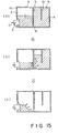
- FIG. 1 - 6 there is shown an ink cartridge having an ink supply opening formed in a wall of a vacuum producing material container that faces a partition wall 5 which cooperates with a bottom surface of the cartridge to form a fine communication port 8.
- Figure 1 is a perspective view of an ink cartridge
- Figure 2 is a sectional view of the ink cartridge.
- the ink cartridge main body 1 is provided with an opening 2 for communication with an ink jet recording head at a position displaced toward the fine communication port in the form of a clearance 8. It comprises a vacuum producing material container 4 for containing the vacuum producing material 3 and an ink container 6 for containing substantially only ink, which communicates with the container 4 at a bottom portion 11 through the clearance 8 provided by the partition wall 5.
- a filter may be provided at an end of the joint member to remove the foreign matter in the ink cartridge.
- ink When the ink jet recording apparatus is operated, ink is ejected out through orifices of the ink jet recording head resulting in an ink absorbing force in the ink cartridge.
- Ink 9 is supplied by the absorbing force from the ink container 6 through the clearance 8 between the bottom end of the partition and the bottom of the ink cartridge 11 to the vacuum producing material container 4, and to the ink jet recording head through the vacuum producing material 3 and the joint member 7.
- the internal pressure or the ink container 6 (which is closed except for the clearance 8)reduces resulting in a pressure difference between the ink container 6 and the vacuum producing material container 4.
- this pressure difference continues to increase.
- the vacuum producing material is open to the ambient air by a clearance 2 between the joint member and the opening. Air is introduced into the ink container 4 through the clearance 8 between the bottom end of the partition member and the internal bottom surface 11 of the ink cartridge through the vacuum producing material.
- the pressure difference between the ink container 6 and the vacuum producing material container is canceled.
- this action is repeated, so that a constant negative pressure (vacuum) is maintained in the ink cartridge.
- Substantially all of the ink in the ink container 6 except for the ink deposited on the internal wall surface of the ink container can be used up, and therefore, the ink use efficiency is improved.
- the capillary force of the vacuum producing material itself meniscus force at the interface between the ink and the vacuum producing material
- the ink retaining state in the vacuum producing material becomes substantially constant.
- the air collected in the ink container is substantially in a certain degree of vacuum, and therefore, the pressure balance in the cartridge is extremely stabilized, so that the ink leakage from the ink jet recording head is suppressed.
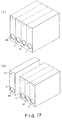
- the ink cartridge in order to use the ink cartridge in a color ink jet recording, various color inks (black, yellow, magenta and cyan) may be accommodated in separate exchangeable ink cartridges, respectively. These ink cartridges may be unified as shown in Figure 17A.
- the exchangeable ink cartridge may comprise a black container exchangeable ink cartridge which is frequently used and one another color exchangeable cartridge, as shown in Figure 17, (B). Any combination is possible in consideration of the ink jet apparatus.
- the following is preferably optimized: material, configuration and dimensions of the vacuum producing material 3, configuration and dimensions of rib end 8, configuration and dimensions of the clearance 8 between the rib end 3 and the ink cartridge bottom 11, volume ratio between the vacuum producing material container 4 and the ink container 6, configuration and dimensions of the joint member 7 and the insertion degree thereof into the ink container, configuration, dimension and mesh of the filter 12, and the surface tension of the ink.
- the material of the vacuum producing member may be any known material if it can retain ink despite the weight thereof, the weight of the liquid (ink) and small vibration.
- the pore density can be adjusted during the manufacturing thereof.
- corresponding pore density foamed materials are required. It is desirable that a foamed material not treated by the thermal compression and having a predetermined number of cells (number of pores per 1 inch) is cut-into a desired dimension, and it is squeezed into the vacuum producing material container so as to provide the desired pore density and the capillary force.
- the clearance is provided between the joint member 7 and the opening 2 for the joint member 7 to permit introduction of the air into the ink cartridge.
- other structures or configurations are usable for the joint member and the joint opening.
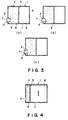
- an end of the joint member 7 is inclined at a certain angle with respect to a joint member inserting direction, since then as shown in Figure 3(a) and (b), the parting of the porous material from the bottom of the ink cartridge is prevented upon insertion of the joint member, and the surface contact between the filter and the vacuum producing material is maintained assuredly. If the insertion amount of the joint member is too large, the tapered end portion might tear the vacuum producing material, and therefore, the surface structure shown in Figure 3, (c), is preferable.
- an outer wall of the joint member is provided with grooves.
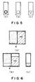
- the configuration of the opening 2 may be a slot (Figure 5, (a)), rectangular ( Figure 5, (b)), triangular ( Figure 5, (c)).
- the preferable configuration of the opening 2 provides a clearance between the joint member, or the configuration is such that it is in contact with the outer periphery of the joint member at the bottom of the opening (bottom of the ink cartridge) and that it is open at the upper portion of the opening.
- the exchangeable ink cartridge has a joint opening functioning also as the air introduction opening, and therefore, the structure is simple.
- the amount of insertion of the joint member 7 into the exchangeable ink cartridge is properly determined by the ordinary skilled in the art so as to provide a compression region of the vacuum producing member to prevent ink leakage upon the insertion and to prevent ink supply stop during the recording operation, in consideration of the configuration of the joint member, the vacuum producing material and the configuration of the ink cartridge.
- the configuration and dimensions of the clearance 8 between the end of the partition wall and the ink cartridge bottom are not limited. However, if it is too small, the meniscus force with the ink is too strong, and although the ink leakage can be prevented through the joint opening, but the ink supply to the vacuum producing material container is difficult, with the possible result of ink supply stop during the use.
- the height to the partition wall of the fine communicating part is preferably larger than an average pore size of the vacuum producing material (average pore size adjacent the fine communication part, preferably) (practically not less than 0.1 mm), and not more than 5 mm. For the purpose of further stabilization, it is preferably not more than 3 mm.
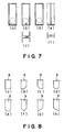
- Figure 7 shows an example of the configuration of the clearance 8.
- Figure 7, (a) shows the most stable structure and configuration.
- Figure 7, (a), (b) and (c), show examples in which the communication part is formed only a part of the entire width of the cartridge, and is waved. This structure is effective when the entire volume of the cartridge is large.
- Figure 7, (d) shows an example having tunnel-like communicating parts with which the ink is easily moved to the inside of the cartridge, and the air introduction can be concentrated.
- a recess is formed along a vertical direction on the partition wall in the ink container. With this structure, the air having come to the bottom end of the partition wall is effectively introduced into the ink container by the recess, thus increasing the air tracking efficiency.
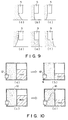
- the clearance 8 is also determined in consideration of the position of the joint opening. Referring to Figure 10, (a) and (b), the partition wall end is at a position lower than the bottom end of the joint opening in Example (a), and the ink retained in the vacuum producing material is lower than the bottom end of the joint opening, and therefore, the leakage preventing effect is sufficient.
- Example (b) the end of the partition wall is at a position higher than the bottom end of the joint opening, and the ink retained in the vacuum producing material is above the bottom end of the joint opening, and therefore, the ink leakage suppressing effect is not sufficient. Therefore, it is preferable to stabilize the advantageous effect of the present invention that the position of the end of the partition wall is not higher than the bottom end of the joint opening by properly determining the dimension of the clearance 8.
- the height of the clearance 8 is selected in the range of 0.1 - 20 mm. Further preferably it ranges from 0.5 - 5 mm approximately.
- the configuration of an end of the partition wall may be any if the consideration is paid to the position relative to the joint opening, as will be understood from Figure 8, (a) - (h).
- the volume ratio between the vacuum producing material container 4 and the ink container 6, is determined in consideration of the ambient condition under which the ink cartridge is used and the ink jet recording apparatus with which it is used. Also, the relation with the used vacuum producing material is important. In order to improve the use efficiency of the ink, it is desirable to increase the volume of the ink container. In that case, a vacuum producing material capable of producing high vacuum (high compression ratio sponge), is effective. Therefore, the preferable ratio ranges from 1:1 - 1:3 practically. In this case, the vacuum producing performance of the vacuum producing member is increased with increase of the relative volume of the ink container.
- the configuration, dimension and mesh of the filter 11 can be properly determined by one skilled in the art depending on the ink jet recording apparatus with which the ink cartridge is used. However, in order to prevent the nozzle from being clogged by the foreign matter introduced from the ink cartridge, the passing area thereof is smaller than the size of the orifice.
- the quantity of the ink in the ink cartridge is not limited except for the internal volume of the ink cartridge.
- the ink may be contained to the extent of the volume limit in the ink container.
- the vacuum producing material is preferably lower than the ink retaining capacity of the material.
- the air and the ink expands in the ink container to push the remaining ink out of the ink cartridge with the possible result of ink leakage.
- the volume of air expansion in the closed ink container including ink expansion (although the amount is small) in accordance with the worst ambient condition change, is estimated, and the amount of the displaced ink from the ink container is to be accommodated in the vacuum producing material container.
- the vacuum producing material container with an air vent in addition to the joint opening, as shown in Figure 10, (c) and (d), since then the ink displaced into the vacuum producing material from the ink chamber by the expansion of the air can be guided toward the air vent.
- the position of the air vent is not limited if it is upper than the joint opening of the vacuum producing member container. However, in order to make the ink flow in the vacuum producing material under the ambient condition change remote from the joint opening, it is preferably away from the joint opening.
- the number, configuration and size of the air vent is properly determined by a person skilled in the art in consideration of the ink evaporation or the like.
- the joint opening and/or the air vent is hermetically sealed by a sealing member to prevent ink evaporation or to be prepared for the expansion of the air in the ink cartridge.
- the sealing member may be a single layer barrier which is so-called barrier material in the packing field, a compound plastic film having several layers, or such material reinforced by paper or cloth or another reinforcing material or aluminum foil It is preferable that a bonding layer of the same material as the main body of the ink cartridge is used to fuse fixing the barrier material, thus improving the hermetical sealing property.
- the packing member may preferably be of the same barrier material as described with respect to the sealing member in consideration of the permeabilities of the liquid and the air.
- the ink does not leak out during the transportation of the ink cartridge itself.
- the material of the main body of the ink cartridge may be any known moldable material if it does not have any adverse influence to the ink jet recording ink or if it has been treated for avoiding the influence.
- the productivity of the ink cartridge is also considered.
- the main body of the ink cartridge is separated into a bottom portion 11 and an upper portion, and they are respectively integrally molded from plastic resin material.
- the vacuum producing material is inserted thereinto, and thereafter, the bottom portion and upper portion are fuse-bonded, thus providing the main body of the ink cartridge.
- the plastic material is transparent or semitransparent, the ink in the ink container can be observed externally, and therefore, the timing of ink cartridge change may be expected.
- the outer surface of the main body of the ink cartridge may be grained.
- the ink can be loaded through pressurizing or pressure-reduction method. Provision of an ink filling opening in either of the containers of the containing main assembly is preferable since then the ink cartridge opening is not contaminated. After the filling, the ink filling opening is plugged by plastic or metal plug.
- the exchangeable ink cartridge is reliable during the transportation thereof, and a high use efficiency ink cartridge can be provided with a simple structure.
- the proper vacuum from the start to the end of the use can be maintained when the recording operation is carried out or is not carried out, while permitting high speed recording.
- the exchangeable ink cartridge of this invention is easy to handle so that the ink does not leak out when it is loaded into the ink jet recording apparatus, and the possibility of erroneous operation can be avoided.
- Figure 11 illustrates a manufacturing method of an ink container cartridge.
- a main body of the cartridge (left down hatching) comprises a partition plate 61 and two containers separated by the partition wall 5.
- An ink absorbing material 4 functioning as the vacuum producing material is inserted into the container portion which is close to the opening 2.
- a bottom member 11 functioning as the covering member is unified to the main body.
- This Figure also shows the state in which the recording head HD is loaded in the ink cartridge 1.
- the ink cartridge 1 is partitioned into two chambers by a partition wall 5, and the bottom portion is covered by a flat bottom member 11 constituting the bottom of the ink cartridge.
- the fine communication port 8 can be provided by the end of the partition wall.
- the air vent 10 is disposed on the same surface as having the opening 2, but above the opening.
- the joint portion 7 functioning as the supply pipe is inserted into the opening of the ink cartridge, and the recording head is mounted thereto.
- the joint portion 7 is inclined so that the top portion is further forward than the bottom portion.
- the ink passage in the joint portion is in the form of a horn opening upwardly in the Figure. With this structure, the ink can be properly supplied to the recording head from the ink absorbing material.
- the ink jet recording apparatus comprises heat generating element 72 for producing thermal energy to eject the ink through ejection outlets 71 of the nozzles 73, wherein the thermal energy is effective to cause state change in the ink.
- heat generating element 72 for producing thermal energy to eject the ink through ejection outlets 71 of the nozzles 73, wherein the thermal energy is effective to cause state change in the ink.
- a high density and fine images can be provided by the stabilized ink supply performance, particularly in the case of color recording.
- the proper vacuum is maintained from the start to the end of the use thereof when the recording operation is carried out or is not carried out, when permitting high speed recording operation.
- the ink leakage can be prevented under the use condition of the ink jet recording apparatus.
- the exchangeable ink cartridge is easy to handle, and the ink does not leak out when it is mounted or demounted relative to the ink jet recording apparatus. Therefore, the erroneous operation in the mounting thereof can be avoided.
- the manufacturing method of the ink cartridge will be described further.
- the closed structure ink chamber (although there is fine communication port between the ink containing chamber and the negative pressure producing material containing chamber, the ink is discharged only when the air and the ink are exchanged with each other), and the vacuum producing material containing chamber are integrally molded, the ink is filled through an opening 13 at the ink container chamber side in the covering member 11.
- the ink is supplied in this manner, a substantial part of the vacuum producing material 4 receives the ink through the fine communication port.
- the region of the vacuum producing material 4 adjacent the air vent is not supplied with the ink to provide ink-free region. Thereafter, the opening 13 is sealed by a ball 14. Then, the opening 2 and the air vent are sealed by the same sealing member S (it may be separate members).
- FIG 12 shows such an ink jet cartridge before start of use.
- the ink container 6 is filled with an ink.
- Figure 12 shows the closed state ink jet cartridge 1 with the printer which is used therewith.
- a region 3A of the vacuum producing material adjacent to the air vent portion 10 does not contain the ink at an upper portion of the cartridge.
- a region 3B of the vacuum producing material below the region 3A is compressed by insertion of the ink supply pipe (not shown).
- the vacuum producing material portion other than those regions 3A and 3B, are not externally influenced and simply functions to retain the ink.
- the region 3B is faced to the opening 2 for the ink supply to the recording head provided on the same surface but below the air vent 10.
- the opening is above the fine communication port 8, and the above-described structure is used.
- the cartridge 1 of Figure 12 becomes usable by removing the sealing member S. Since the region A does not retain the ink, the ink does not leak out even if the vibration or pressure change is imparted upon the removal of the sealing member.
- the ink is not retained in the region of the vacuum producing member that is close to the air vent or air communication port, irrespective of whether the ink cartridge is being used or not used.
- the leakage of the ink from the ink cartridge through the air vent can be prevented even when the ambient condition varies.
- the sealing member closes the air vent the sealing member can be prevented from peeling off.
- the region is effective to permit air supply corresponding to the consumption of the ink, so that the change of the vacuum in the ink cartridge can be suppressed. If the region of the vacuum producing material adjacent to the air vent has never been wetted by the ink at all, it is preferable to decelerate the ink seeping speed. However, the region thereof may be wetted by the ink beforehand, and thereafter, the ink may be removed from this region.
- the ink supply opening or the compressed part of the vacuum producing material (compressible) by the ink supply pipe is present at a side opposed to the partition wall constituting the fine communication port, by which the effective ink supply path can be stably provided in the vacuum producing material in the second accommodation chamber. This can be further stabilized by placing the ink supply opening above the fine communication port relative to the bottom surface of the ink cartridge.
- the ink moving direction can be substantially made constant, and therefore, the ink can be completely consumed from the second chamber, that is, the ink container chamber.
- the ink container chamber After the ink in the ink container chamber has been used up, air moves the ink toward the opening from the partition wall in the direction to cancel the vacuum in the ink container chamber, as a result, the ink in the vacuum producing material can be consumed further, thus minimizing the nonusable remaining amount of the ink.
- the non-compressed region provides a one-way ink path, and the ink retaining capacity of the compressed region can further reduce the remaining amount of the ink.
- the ink jet printer is provided with a recording head recovery means HR which carries out ink ejection or ink sucking by sucking means automatically or manually in response to mounting of the cartridge 1 thereto.
- a recording head recovery means HR which carries out ink ejection or ink sucking by sucking means automatically or manually in response to mounting of the cartridge 1 thereto.
- the ink cartridge 1 mounted to the ink jet head HD mounted on a scanning type carriage CR has been deprived of the sealing tape.
- the cartridge mounted on the carriage CR receives through the opening 2 the ink supply pipe, by which the vacuum producing material 3 is compressed in the compressible region 3b.
- the vacuum producing member 3 is deformed toward the fine communication port 8.
- the mounting of the container is detected by detecting means (not shown) in the form of mechanical or electrical detecting means, which produces mounting signal IT into the printer control means CC.
- the recovery means HR is actuated before the start of the recording operation to discharge the ink in the ink cartridge, thus improving the state of the ink in the ink cartridge.
- FIG 13 (A) and (B) show an inclination range capable of printing operation or ink supply.
- Designated by a reference numeral 40 is a horizontal line. It is preferable that the fine communication port is at a lower position. Ideally, the bottom surface of the cartridge is parallel with the horizontal plane 40. Practically, however, in the case of two chamber structure as in this embodiment, the inclination is permissible in the range, 0 ⁇ ⁇ ⁇ 15 degrees. When it is reciprocated on a scanning carriage, it is preferably 0 ⁇ ⁇ ⁇ 5 degrees.
- the vacuum producing material used be constituted by a plurality of vacuum producing material members. However, in that case, the resultant interface between the members might permit movement of the air at the interface, as the case may be. In view of this, single porous material member is preferable for the vacuum producing material.
- the ink container performs it function if it has an ink capacity larger than that of the vacuum producing material accommodating chamber.
- the description will be made as a partition plate 61 in the ink accommodating chamber.
- the external wall of the cartridge may be deformed with the possible result that the ink is leaked through the orifice from the ink jet recording head or that the ink is leaked out through the air vent provided for equalizing the pressure in the cartridge with the ambient pressure.
- this problem is solved, thus preventing the ink leakage during the handling or during the transportation or even if the temperature or the pressure changes.
- the use efficiency is still high.
- Figure 14 (A) is a perspective view of the ink container of this embodiment, and Figure 14, (B), is a sectional view thereof.
- Figure 15 illustrates ink supply operation of this embodiment.
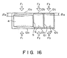
- Figure 16 illustrates deformation of the side wall when it receives load.
- the main body of the ink cartridge 1 comprises an opening 2 for communication with the ink jet recording head and an air vent 10 for permitting introduction of the air, disposed above the opening 2, vacuum producing material 3 for retaining the ink for the recording, a vacuum producing material container 4 for containing the vacuum producing material 3 and provided with the opening 2 and the air vent 10, and an ink container (chamber) 6 for containing the ink in communication with the vacuum producing material container 4 through a clearance below a rib 5.
- the ink container 6 and the vacuum producing material container 4 communicate with each other through a clearance 8 formed between an end of the rib 5 and the bottom surface.
- a partition plate 61 connects the opposite side walls leaving a gap not less than the clearance 8 at the bottom.
- FIG 15 is a sectional view in the state in which the ink jet recording apparatus is operable after a joint member 7 for supplying the ink to the ink jet recording head is inserted into the opening 2 of the ink cartridge main body 1 to press-contact the vacuum producing material 3.
- the end opening of the joint member 7 may be provided with a filter to remove foreign matters in the ink cartridge.
- ink jet recording apparatus When the ink jet recording apparatus is operated, ink is ejected through the orifice of the ink jet recording head, so that ink absorbing force is produced in the ink container.
- the ink 9 is supplied to the ink jet recording head from the ink container 6 through the clearance 8 between an end of the rib 5 and the bottom of the ink cartridge 11 to the vacuum producing material container 4, and through the vacuum producing material 3 to the joint member 7.
- the pressure of the ink container 6 which is closed except for the clearance 8, reduces with the result of pressure difference between the ink container 6 and the vacuum producing material container 4.
- the pressure difference continues to increase since the vacuum producing material container 4 is open to the air through the air vent 10.
- the capillary force of the vacuum producing material 3 itself appears to prevent the leakage of the ink from the ink jet recording head.
- the ink cartridge it is desirable that the ink cartridge is durable against external force and the ambient condition change during the transportation, while maintaining high use efficiency.
- the amount of deformations are equivalent in the vacuum producing member container 4 and the ink container 6 when the external forces are applied to the side walls 12a, 12b and 12c.
- the cartridge is usually made by molding a plastic material.
- the thickness of the side wall 12a of the vacuum producing material container 4 is larger than the thickness of the side walls 12b and 12c of the ink container portion 6, and a partition wall (rib) 61 is disposed to extend between the opposite side walls, leaving the clearance at the bottom, at a position to divide the space into two equal spaces in the ink container 6.
- the deformation ⁇ t6 of the wall responsive to the equivalent loads per unit area is reduced , and the deformations of the side walls 12b and 12c at the opposite ends of the rib 61, are equivalent.
- the amount of deformation ⁇ t4 of the vacuum producing material container 4 equivalent thereto, the leakage of the ink due to the deformation of the wall can be prevented.
- the material of the wall is polypropylene (PP), and the outer dimensions are as follows: 48 mm in length, 55 mm in height, 11 mm in thickness. In this case, it is divided into the vacuum producing material container 4 and the ink container 6 substantially at the center of the length of 48 mm.
- the side wall 12a of the vacuum producing material container 4 has a thickness of 1.5 mm
- the side walls 12b and 12c of the ink container 6 have a thickness of 1 mm
- the rib 61 of the ink container 6 is disposed approx. 10 mm away from the wall surface.
- only one rib 61 is provided in the ink container 6 because of the size of the ink container.
- the number thereof is not limited, and two ribs 61 may be provided in accordance with the size of the ink cartridge.
- the number, position and the wall thickness of the rib can be properly determined by those skilled in the art.
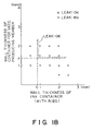
- Figure 18 shows the relation of the ink leakage during the handling and the transportation with the wall thickness of the vacuum producing material container 4 and wall thicknesses of various walls, investigated for the purpose of determining the wall thickness of the ink container 6.
- the above-described dimension may be determined on the basis of the data of this Figure. It is preferable that the wall thickness of the vacuum producing material container 4 is 1.3 - 3 times the wall thickness of the ink container 6.
- embodiments of the present invention enable the provision of an exchangeable ink cartridge, an ink jet head and a printer using the same capable of effecting high speed recording, while the vacuum can be maintained substantially constant during a large part of the period from the start to the end of use of the ink cartridge.
- an exchangeable ink cartridge in accordance with the present invention enable a vacuum to be produced in the ink cartridge when the recording operation is not effected, thus preventing ink leakage through an opening upon impact.
- inventions of the present invention provide exchangeable ink cartridges which are less expensive and from which ink does not leak during transportation.
- An ink cartridge embodying the invention is usually handled by an operator, and therefore, it is possible that strong forces are applied thereto with the result of deformation of the ink container wall.
- an additional partition wall providing a larger clearance than the fine communication port in the ink container for containing substantially only the ink is provided.
- the thickness of the wall of the chamber containing substantially only ink is 0.8mm or more and that the wall thickness of the chamber containing the vacuum producing material such as sponge is 1.3mm from the standpoint of the prevention of the deformation.
- ink is forcibly discharged by sucking the ink by the sucking means and by ejecting the ink by ejecting means automatically or manually upon mounting of the cartridge on the ink jet printer.
- This is preferable because the state of the ink in the vacuum generating material can be adjusted before the start of the printing operation, and therefore, the printing function can be performed without influence of the ink cartridge keeping state.
- the height of the fine communication port provided by the partition wall is larger than an average pore size of the vacuum producing material (preferably the average pore size in the region adjacent the fine communication port) (practically not less than 0.1 mm), and it is preferably not less than 5 mm. If it is less than 3 mm, further stabilization can be expected.
- the volume ratio of the vacuum producing material container and the ink container is not less than 1:1 and not more than 1:3, practically.
Landscapes
- Ink Jet (AREA)
- Magnetic Resonance Imaging Apparatus (AREA)
- Particle Formation And Scattering Control In Inkjet Printers (AREA)
- Pens And Brushes (AREA)
- Endoscopes (AREA)
- Ink Jet Recording Methods And Recording Media Thereof (AREA)
Claims (24)
- Verfahren zur Herstellung einer Tintenpatrone (1), welche eine Auslaßöffnung (2) zum Anschließen an einen Tintenstrahlkopf für ein Tintenstrahlaufzeichnungsgerät und einen Luftkanal (10) hat, wobei das Verfahren folgende Schritte aufweist: Bereitstellung eines einstückigen Körpers, welcher einen ersten und einen zweiten, von einer Trennwand (5) getrennten Abschnitt definiert, Einsetzen eines Negativdruck erzeugenden Materials (4) in den ersten Abschnitt und Ankleben eines Abdeckelementes (11) an den einstückigen Körper zum Verschließen des ersten und des zweiten Abschnitts, so daß das Abdeckelement zusammen mit dem ersten Abschnitt eine erste Kammer (3) mit vorhandener Auslaßöffnung und vorhandenem Luftkanal und zusammen mit dem zweiten Abschnitt eine zweite Kammer (6) bildet, welche das Tintenreservoir für die erste Kammer darstellt und mit Ausnahme der Verbindungsöffnung (8), die zwischen der ersten und der zweiten Kammer und zwischen der Trennwand und dem Abdeckelement vorhanden ist, eine abgedichtete Einheit ergibt.
- Verfahren zur Herstellung einer Tintenpatrone (1), welche eine Auslaßöffnung (2) zum Anschließen an einen Tintenstrahlkopf für ein Tintenstrahlaufzeichnungsgerät und einen Luftkanal (10) hat, wobei das Verfahren folgende Schritte aufweist: Bereitstellung eines einstückigen Körpers mit Vorderwand, Rückwand, Oberwand und zwei Seitenwänden und einer sich zwischen den beiden Seitenwänden erstreckenden Trennwand (5), um den einstückigen Körper in einen von der Trennwand, der Vorderwand, der Oberwand und den beiden Seitenwänden gebildeten ersten Abschnitt und einen von der Trennwand, der Rückwand, der Oberwand und den beiden Seitenwänden gebildeten zweiten Abschnitt zu trennen, Einsetzen eines schwammartigen, absorbierenden, Negativdruck erzeugenden Materials (4) in den ersten Abschnitt durch den offenen Boden des einstückigen Körpers und Ankleben eines Bodenabdeckelements (11) an den einstückigen Körper, so daß das Bodenabdeckelement zusammen mit dem ersten Abschnitt eine erste Kammer (3), welche das absorbierende Material enthält und mit der Tintenauslaßöffnung und dem Luftkanal versehen ist, und zusammen mit dem zweiten Abschnitt eine zweite Kammer (6) erzeugt, welche das Tintenreservoir für die erste Kammer bildet, und die Bodenwand und die Trennwand eine Öffnung definieren, welche die Verbindungsöffnung zwischen der ersten und der zweiten Kammer darstellt.
- Verfahren gemäß Anspruch 1 oder 2, welches die Bereitstellung eines einstückigen Körpers aufweist, bei welchem die Tintenauslaßöffnung (2) in der Wand vorhanden ist, welche der Trennwand gegenüberliegt, und der Luftkanal (10) in der Wand vorhanden ist, welche dem Abdeckelement gegenüberliegt, wenn dieses am einstückigen Körper befestigt ist.
- Verfahren gemäß Anspruch 1, 2 oder 3, welches außerdem das Einbringen von Tinte in die Patrone aufweist, um ein Tintenreservoir in der zweiten Kammer (6) zu erzeugen und die erste Kammer (3) teilweise zu füllen.
- Verfahren gemäß Anspruch 4, welches das Einbringen von Tinte durch die abdichtbare Zugangsöffnung (13) der zweiten Kammer und dann das Abdichten der Zugangsöffnung mit einem Abdichtelement (14) aufweist.
- Verfahren gemäß Anspruch 5, welches die Verwendung einer Kugel (14) als Abdichtelement und das Abdichten der Zugangsöffnung durch Einsetzen der Kugel in die Zugangsöffnung (13) aufweist.
- Verfahren gemäß einem der vorstehenden Ansprüche, wobei das abdichtende Befestigen des Abdeckelements (11) am einstückigen Körper eine Öffnung von 0.1 bis 20 mm zwischen der Trennwand (5) und dem Abdeckelement definiert.
- Verfahren gemäß Anspruch 7, wobei das Ankleben des Bodenabdeckelements am einstückigen Körper eine Öffnung von 0,5 bis 5 mm zwischen der Trennwand (5) und dem Abdeckelement (11) definiert.
- Verfahren gemäß einem der vorstehenden Ansprüche, welche das Bereitstellen des einstückigen Körpers und das Ankleben des Bodenelements (11) am einstückigen Körper aufweist, so daß die erste Kammer (3) und die zweite Kammer (6) ein Volumenverhältnis von 1:1 bis 3:1 haben.
- Verfahren gemäß einem der vorstehenden Ansprüche, welches die Bereitstellung des einstückigen Körpers und des Abdeckelements (11) aus einem transparenten oder halbtransparenten Plastmaterial aufweist.
- Tintenpatrone, welche eine an einen Tintenstrahlkopf für ein Tintenstrahlaufzeichnungsgerät anschließbare Tintenauslaßöffnung (2) und einen Luftkanal (10) hat, wobei die Patrone folgende Elemente aufweist: einen einstückigen Körper, welcher einen durch die Trennwand (5) geteilten ersten und zweiten Abschnitt definiert, ein Negativdruck erzeugendes Material (4) im ersten Abschnitt und ein am einstückigen Körper zum Abdichten des ersten und des zweiten Abschnitts abdichtend angebrachtes Abdeckelement (11) aufweist, so daß das Abdeckelement (11) zusammen mit dem ersten Abschnitt eine erste Kammer (3), welche die Tintenauslaßöffnung und den Luftkanal hat, und zusammen mit dem zweiten Abschnitt eine zweite Kammer (4) bildet, welche als Tintenreservoir für die erste Kammer dient und welche mit Ausnahme der zwischen der ersten und der zweiten Kammer vorhandenen und zwischen der Trennwand (5) und dem Abdeckelement (11) definierten Verbindungsöffnung (8) geschlossen ist.
- Tintenpatrone, welche eine an einen Tintenstrahlkopf für ein Tintenstrahlaufzeichnungsgerät anschließbare Tintenauslaßöffnung (2) und einen Luftkanal (10) hat, wobei die Patrone folgende Elemente aufweist: einen einstückigen Körper, welcher eine Vorderwand, eine Rückwand, eine Oberwand und zwei Seitenwände und eine zwischen den beiden Seitenwänden sich erstreckende Trennwand (5) hat, um den einstückigen Körper in einen von der Trennwand, Vorderwand, Oberwand und den beiden Seitenwänden gebildeten ersten Abschnitt und einen von der Trennwand, Rückwand, Oberwand und den beiden Seitenwänden gebildeten zweiten Abschnitt zu trennen, ein schwammähnliches, absorbierendes, Negativdruck erzeugendes Material (4) im ersten Abschnitt und ein am einstückigen Körper abdichtend angebrachtes Bodenabdeckelement (11), so daß das Bodenabdeckelement zusammen mit dem ersten Abschnitt eine erste Kammer (3), welche das absorbierende Material (4) enthält und die Tintenauslaßöffnung und den Luftkanal hat, und zusammen mit dem zweiten Abschnitt eine zweite Kammer (6) bildet, welche als Tintenreservoir für die erste Kammer dient, und wobei die Bodenwand und die Trennwand (5) eine Öffnung definieren, welche die Verbindungsöffnung (8) zwischen der ersten und der zweiten Kammer darstellt.
- Tintenstrahlpatrone gemäß Anspruch 11 oder 12, wobei die Tintenauslaßöffnung (2) in der Wand, welche der Trennwand gegenüberliegt, und der Luftkanal (10) in der Wand, welche dem Abdeckelement nach dessen Befestigung am einstückigen Körper gegenüberliegt, erzeugt ist.
- Tintenstrahlpatrone gemäß Anspruch 11, 12 oder 13, wobei die zweite Kammer (6) ein Tintenreservoir bildet und Tinte enthält und die erste Kammer (3) teilweise mit Tinte gefüllt ist.
- Tintenstrahlpatrone gemäß Anspruch 14, wobei die für das Einfüllen von Tinte vorgesehene abdichtbare Zugangsöffnung (13) der zweiten Kammer durch eine einsetzbare Kugel (14) abgedichtet wird.
- Tintenstrahlpatrone gemäß einem der Ansprüche 11 bis 15, wobei zwischen der Trennwand (5) und dem Abdeckelement (11) eine Öffnung von 0,1 bis 20 mm definiert ist.
- Tintenstrahlpatrone gemäß Anspruch 16, wobei zwischen der Trennwand (5) und dem Abdeckelement (11) eine Öffnung von 0,5 bis 5 mm definiert ist.
- Tintenstrahlpatrone gemäß einem der Ansprüche 11 bis 17, wobei die erste Kammer (3) und die zweite Kammer (6) ein Volumenverhältnis von 1:1 bis 3:1 haben.
- Tintenstrahlpatrone gemäß einem der Ansprüche 11 bis 18, wobei der einstückige Körper und das Abdeckelement (11) aus einem transparenten oder halbtransparentem Plastmaterial gefertigt sind.
- Tintenstrahlpatrone gemäß einem der Ansprüche 11 bis 19, wobei die Trennwand (5) die Öffnung, welche sich über deren gesamte Breite erstreckt, als Verbindungsöffnung definiert.
- Tintenstrahlpatrone gemäß einem der Ansprüche 11 bis 20, wobei die erste und die zweite Kammer durch eine geneigte Trennwand (51) voneinander getrennt sind.
- Tintenstrahlpatrone gemäß einem der Ansprüche 11 bis 21, wobei bei Einsatz der Patrone die Verbindungsöffnung (8) unterhalb der Tintenauslaßöffnung (2) angeordnet ist.
- Tintenstrahlpatrone gemäß einem der Ansprüche 11 bis 22, wobei die Innenoberfläche (20, 22) der zweiten Kammer gekrümmt ist und sich von der Verbindungsöffnung abhebt.
- Tintenstrahlpatrone gemäß einem der Ansprüche 11 bis 23, wobei die zweite Kammer (6) eine verformungshemmende Platte (61) einschließt, welche zusammen mit den Wänden der zweiten Kammer eine Öffnung definiert, die größer ist als die Verbindungsöffnung (8).
Priority Applications (6)
| Application Number | Priority Date | Filing Date | Title |
|---|---|---|---|
| EP98200112A EP0839663B1 (de) | 1992-07-24 | 1993-07-22 | Tintenstrahlpatrone, Tintenstrahlkopf und Drucker |
| EP00203803A EP1077132B1 (de) | 1992-07-24 | 1993-07-22 | Tintenstrahlpatrone, Tintenstrahlkopf und Drucker |
| EP98200111A EP0839662B1 (de) | 1992-07-24 | 1993-07-22 | Tintenstrahlpatrone, Tintenstrahlkopf und Drucker |
| EP00203802A EP1075951B1 (de) | 1992-07-24 | 1993-07-22 | Tintenstrahlpatrone, Tintenstrahlkopf und Drucker |
| EP98200110A EP0839661B1 (de) | 1992-07-24 | 1993-07-22 | Tintenstrahlpatrone, Tintenstrahlkopf und Drucker |
| EP98200109A EP0838340B1 (de) | 1992-07-24 | 1993-07-22 | Tintenstrahlpatrone, Tintenstrahlkopf und Drucker |
Applications Claiming Priority (6)
| Application Number | Priority Date | Filing Date | Title |
|---|---|---|---|
| JP19847492 | 1992-07-24 | ||
| JP198474/92 | 1992-07-24 | ||
| JP19847492 | 1992-07-24 | ||
| JP12262093 | 1993-05-25 | ||
| JP122620/93 | 1993-05-25 | ||
| JP12262093 | 1993-05-25 |
Related Child Applications (4)
| Application Number | Title | Priority Date | Filing Date |
|---|---|---|---|
| EP98200112A Division EP0839663B1 (de) | 1992-07-24 | 1993-07-22 | Tintenstrahlpatrone, Tintenstrahlkopf und Drucker |
| EP98200110A Division EP0839661B1 (de) | 1992-07-24 | 1993-07-22 | Tintenstrahlpatrone, Tintenstrahlkopf und Drucker |
| EP98200109A Division EP0838340B1 (de) | 1992-07-24 | 1993-07-22 | Tintenstrahlpatrone, Tintenstrahlkopf und Drucker |
| EP98200111A Division EP0839662B1 (de) | 1992-07-24 | 1993-07-22 | Tintenstrahlpatrone, Tintenstrahlkopf und Drucker |
Publications (2)
| Publication Number | Publication Date |
|---|---|
| EP0580433A1 EP0580433A1 (de) | 1994-01-26 |
| EP0580433B1 true EP0580433B1 (de) | 1999-10-06 |
Family
ID=26459714
Family Applications (7)
| Application Number | Title | Priority Date | Filing Date |
|---|---|---|---|
| EP93305770A Expired - Lifetime EP0580433B1 (de) | 1992-07-24 | 1993-07-22 | Tintenstrahlpatrone |
| EP00203803A Expired - Lifetime EP1077132B1 (de) | 1992-07-24 | 1993-07-22 | Tintenstrahlpatrone, Tintenstrahlkopf und Drucker |
| EP98200112A Expired - Lifetime EP0839663B1 (de) | 1992-07-24 | 1993-07-22 | Tintenstrahlpatrone, Tintenstrahlkopf und Drucker |
| EP98200109A Expired - Lifetime EP0838340B1 (de) | 1992-07-24 | 1993-07-22 | Tintenstrahlpatrone, Tintenstrahlkopf und Drucker |
| EP00203802A Expired - Lifetime EP1075951B1 (de) | 1992-07-24 | 1993-07-22 | Tintenstrahlpatrone, Tintenstrahlkopf und Drucker |
| EP98200111A Expired - Lifetime EP0839662B1 (de) | 1992-07-24 | 1993-07-22 | Tintenstrahlpatrone, Tintenstrahlkopf und Drucker |
| EP98200110A Expired - Lifetime EP0839661B1 (de) | 1992-07-24 | 1993-07-22 | Tintenstrahlpatrone, Tintenstrahlkopf und Drucker |
Family Applications After (6)
| Application Number | Title | Priority Date | Filing Date |
|---|---|---|---|
| EP00203803A Expired - Lifetime EP1077132B1 (de) | 1992-07-24 | 1993-07-22 | Tintenstrahlpatrone, Tintenstrahlkopf und Drucker |
| EP98200112A Expired - Lifetime EP0839663B1 (de) | 1992-07-24 | 1993-07-22 | Tintenstrahlpatrone, Tintenstrahlkopf und Drucker |
| EP98200109A Expired - Lifetime EP0838340B1 (de) | 1992-07-24 | 1993-07-22 | Tintenstrahlpatrone, Tintenstrahlkopf und Drucker |
| EP00203802A Expired - Lifetime EP1075951B1 (de) | 1992-07-24 | 1993-07-22 | Tintenstrahlpatrone, Tintenstrahlkopf und Drucker |
| EP98200111A Expired - Lifetime EP0839662B1 (de) | 1992-07-24 | 1993-07-22 | Tintenstrahlpatrone, Tintenstrahlkopf und Drucker |
| EP98200110A Expired - Lifetime EP0839661B1 (de) | 1992-07-24 | 1993-07-22 | Tintenstrahlpatrone, Tintenstrahlkopf und Drucker |
Country Status (14)
| Country | Link |
|---|---|
| US (7) | US5619238A (de) |
| EP (7) | EP0580433B1 (de) |
| KR (1) | KR0145750B1 (de) |
| CN (6) | CN1073510C (de) |
| AT (7) | ATE211970T1 (de) |
| AU (1) | AU4215693A (de) |
| CA (1) | CA2101017C (de) |
| DE (7) | DE69331474T2 (de) |
| DK (3) | DK0838340T3 (de) |
| ES (5) | ES2170992T3 (de) |
| GB (1) | GB2268910B (de) |
| HK (3) | HK1008396A1 (de) |
| PT (3) | PT838340E (de) |
| SG (4) | SG83726A1 (de) |
Families Citing this family (131)
| Publication number | Priority date | Publication date | Assignee | Title |
|---|---|---|---|---|
| JP3327046B2 (ja) * | 1995-04-21 | 2002-09-24 | セイコーエプソン株式会社 | 記録装置用インクタンクならびにインクタンクのインク補給方法 |
| US6247803B1 (en) | 1983-10-13 | 2001-06-19 | Seiko Epson Corporation | Ink jet recording apparatus and method for replenishing ink in the tank cartridge |
| US6145974A (en) * | 1983-10-13 | 2000-11-14 | Seiko Epson Corporation | Ink-supplied printer head and ink container |
| JP3513979B2 (ja) * | 1994-09-16 | 2004-03-31 | セイコーエプソン株式会社 | インクジェットプリンタ用インクカートリッジ |
| US6276785B1 (en) * | 1983-10-13 | 2001-08-21 | Seiko Epson Corporation | Ink-supplied printer head and ink container |
| US6474798B1 (en) | 1984-10-11 | 2002-11-05 | Seiko Epson Corporation | Ink supplied printer head and ink container |
| CA2290700C (en) * | 1992-07-24 | 2004-08-31 | Canon Kabushiki Kaisha | Ink container, ink and ink jet recording apparatus using ink container |
| US5619238A (en) * | 1992-07-24 | 1997-04-08 | Canon Kabushiki Kaisha | Method of making replaceable ink cartridge |
| JP3043926B2 (ja) * | 1993-08-20 | 2000-05-22 | キヤノン株式会社 | インクカートリッジ |
| US6332675B1 (en) | 1992-07-24 | 2001-12-25 | Canon Kabushiki Kaisha | Ink container, ink and ink jet recording apparatus using ink container |
| EP0839657B1 (de) * | 1993-05-13 | 2001-11-07 | Canon Kabushiki Kaisha | Tintenbehälter, Druckkopfkassette und Tintenstrahldrucker |
| US6286944B1 (en) | 1993-05-21 | 2001-09-11 | Canon Kabushiki Kaisha | Ink jet unit with cartridge having controlled ink flow |
| ATE187930T1 (de) * | 1993-05-21 | 2000-01-15 | Canon Kk | Tintenstrahleinheit |
| JP3133906B2 (ja) * | 1993-08-19 | 2001-02-13 | キヤノン株式会社 | インクタンクカートリッジ |
| DE4328001C2 (de) * | 1993-08-20 | 1997-03-20 | Dia Nielsen Gmbh | Tintenbehälter |
| EP0640482B1 (de) * | 1993-08-23 | 2002-04-10 | Canon Kabushiki Kaisha | Auswechselbare Tintenpatrone |
| JP3285676B2 (ja) | 1993-08-25 | 2002-05-27 | キヤノン株式会社 | インク終了検知装置、およびインクジェット記録装置のインク終了検知方法 |
| DE69424724T2 (de) * | 1993-08-31 | 2000-11-23 | Canon K.K., Tokio/Tokyo | Verfahren und Gerät zum Befüllen von Tintenpatronen mit Tinte |
| JP3238805B2 (ja) * | 1993-09-30 | 2001-12-17 | キヤノン株式会社 | インクタンク、インクジェット用カートリッジ及びインクジェット記録方法 |
| US6238042B1 (en) * | 1994-09-16 | 2001-05-29 | Seiko Epson Corporation | Ink cartridge for ink jet printer and method of charging ink into said cartridge |
| DE19549524B4 (de) * | 1994-09-16 | 2004-11-25 | Seiko Epson Corp. | Tintenpatrone für ein Tintenstrahlaufzeichnungsgerät |
| DE19534578C2 (de) * | 1994-09-16 | 2000-01-20 | Seiko Epson Corp | Tintenpatrone |
| CN100584619C (zh) * | 1994-09-16 | 2010-01-27 | 精工爱普生株式会社 | 一种喷墨式记录设备用的墨盒 |
| DE19549529B4 (de) * | 1994-09-16 | 2005-12-01 | Seiko Epson Corp. | Tintenpatrone für ein Tintenstrahlaufzeichnungsgerät |
| DE19549778B4 (de) * | 1994-09-16 | 2006-03-09 | Seiko Epson Corp. | Tintenpatrone für ein Tintenstrahlaufzeichnungsgerät |
| US6771378B2 (en) | 1994-10-20 | 2004-08-03 | Canon Kabushiki Kaisha | Information processing apparatus which obtains information concerning residual ink amount from an attached ink jet printer |
| DE69526302T2 (de) | 1994-11-07 | 2002-11-14 | Canon Aptex Inc., Mitsukaido | Drucker mit zugehöriger Tintenkassette |
| US6010213A (en) * | 1994-11-18 | 2000-01-04 | Seiko Epson Corporation | Ink supply device for use in ink jet printer and ink tank for use in the same device |
| JP3347559B2 (ja) | 1994-12-28 | 2002-11-20 | キヤノン株式会社 | インクタンク及びインクジェットカートリッジならびにインクジェット記録装置 |
| JP3308751B2 (ja) * | 1995-02-21 | 2002-07-29 | キヤノン株式会社 | インクタンク及びその製造方法 |
| US5953030A (en) * | 1995-04-24 | 1999-09-14 | Canon Kabushiki Kaisha | Ink container with improved air venting structure |
| JP3479392B2 (ja) * | 1995-08-01 | 2003-12-15 | ブラザー工業株式会社 | インクカートリッジの連結構造 |
| JP3158022B2 (ja) * | 1995-10-16 | 2001-04-23 | シャープ株式会社 | インクジェット記録装置 |
| JP3507261B2 (ja) * | 1995-12-26 | 2004-03-15 | キヤノン株式会社 | 液体吐出ヘッド用液体供給方法、及び液体吐出記録装置 |
| JP3394864B2 (ja) * | 1996-01-22 | 2003-04-07 | ブラザー工業株式会社 | インクカートリッジおよびインクジェット記録装置 |
| DE19603195A1 (de) * | 1996-01-30 | 1997-07-31 | Pms Gmbh Prod & Recycling | Tintenpatrone für einen Druckkopf eines Tintenstrahldruckers |
| JP3450643B2 (ja) * | 1996-04-25 | 2003-09-29 | キヤノン株式会社 | 液体収容容器への液体補充方法、該補充方法を用いる液体吐出記録装置、液体補充容器、液体収容容器およびヘッドカートリッジ |
| JP3684022B2 (ja) | 1996-04-25 | 2005-08-17 | キヤノン株式会社 | 液体補充方法、液体吐出記録装置および該液体吐出記録装置のメインタンクとして用いられるインクタンク |
| KR100338451B1 (ko) * | 1996-07-05 | 2002-10-11 | 세이코 엡슨 가부시키가이샤 | 잉크카트리지및잉크카트리지용로딩기구 |
| DE69725067T2 (de) | 1996-07-09 | 2005-02-17 | Canon K.K. | Flüssigkeitsausstosskopf, Kassette für einen Flüssigkeitsausstosskopf und Flüssigkeitsausstossapparat |
| JP3332779B2 (ja) * | 1996-07-31 | 2002-10-07 | キヤノン株式会社 | インクジェット記録装置用液体収納容器 |
| JPH10138507A (ja) * | 1996-11-14 | 1998-05-26 | Seiko Epson Corp | インクジェット式記録装置用インクカートリッジの製造方法 |
| JP3513377B2 (ja) * | 1996-12-05 | 2004-03-31 | キヤノン株式会社 | 液体収容容器への液体充填方法、該充填方法を実施するための充填ユニットと該充填方法により製造された液体収容容器、及び液体吐出記録装置 |
| MX9801290A (es) * | 1997-02-19 | 1998-11-30 | Canon Cabushiki Kaisha | Envase de liquido para cabeza de chorron de tinta. |
| JP3746870B2 (ja) | 1997-03-07 | 2006-02-15 | セイコーエプソン株式会社 | インクジェット式記録装置用インクカートリッジ |
| JP3453492B2 (ja) * | 1997-05-13 | 2003-10-06 | キヤノン株式会社 | 画像形成装置及びプリンタヘッド |
| AUPP654098A0 (en) * | 1998-10-16 | 1998-11-05 | Silverbrook Research Pty Ltd | Micromechanical fluid supply system (fluid05) |
| US6257712B1 (en) * | 1997-11-14 | 2001-07-10 | Brother Kogyo Kabushiki Kaisha | Ink feeder |
| JP3880232B2 (ja) * | 1997-12-25 | 2007-02-14 | キヤノン株式会社 | 液体供給方法、該液体供給方法を用いる液体供給システム、インクタンク |
| DE69918368T2 (de) | 1998-04-28 | 2005-08-18 | Canon K.K. | Tintenstrahlaufzeichnungsvorrichtung |
| US6095643A (en) * | 1998-05-07 | 2000-08-01 | Lexmark International, Inc. | Refillable disposable inkjet cartridge with foam-filled and free ink reservoirs |
| FR2782032B1 (fr) * | 1998-08-10 | 2000-10-06 | Siantec | Machine d'impression directe par projection de gouttes d'encre sur un support |
| US6616270B1 (en) * | 1998-08-21 | 2003-09-09 | Seiko Epson Corporation | Ink jet recording head and ink jet recording apparatus comprising the same |
| US6631986B2 (en) * | 1998-12-16 | 2003-10-14 | Silverbrook Research Pty Ltd | Printer transport roller with internal drive motor |
| JP3667127B2 (ja) | 1998-12-24 | 2005-07-06 | キヤノン株式会社 | 液体供給システムの液体残量検出方法 |
| JP3592112B2 (ja) | 1998-12-24 | 2004-11-24 | キヤノン株式会社 | 液体供給システム、液体収納容器、およびヘッドカートリッジ |
| JP3706782B2 (ja) | 1999-04-15 | 2005-10-19 | キヤノン株式会社 | 繊維積層体の製造方法、該方法によって製造された繊維積層体及び該繊維積層体を収納した液体収納容器、該容器を有した液体吐出ヘッドカートリッジ |
| JP2001063098A (ja) | 1999-04-27 | 2001-03-13 | Canon Inc | 液体収納容器、該液体収納容器に用いられる弁機構および液体供給容器 |
| JP3450798B2 (ja) | 1999-04-27 | 2003-09-29 | キヤノン株式会社 | 液体供給システム、該システムに用いられる液体収納容器、該システムを用いたインクジェットヘッドカートリッジ |
| JP2001063097A (ja) | 1999-04-27 | 2001-03-13 | Canon Inc | 液体供給システム及び該システムに用いられる液体供給容器 |
| US6443567B1 (en) | 1999-04-27 | 2002-09-03 | Canon Kabushiki Kaisha | Liquid ejecting cartridge and recording device using same |
| US7383727B2 (en) | 1999-05-20 | 2008-06-10 | Seiko Epson Corporation | Liquid cotainer having a liquid consumption detecting device therein |
| AUPQ439299A0 (en) * | 1999-12-01 | 1999-12-23 | Silverbrook Research Pty Ltd | Interface system |
| US6450631B1 (en) | 1999-06-24 | 2002-09-17 | Canon Kabushiki Kaisha | Storing method of ink tank and ink jet head cartridge, and ink tank and storing container used in the same method |
| JP2001001544A (ja) | 1999-06-24 | 2001-01-09 | Canon Inc | 液体供給方法、液体供給容器、負圧発生部材収納容器及び液体収納容器 |
| JP2001001542A (ja) | 1999-06-24 | 2001-01-09 | Canon Inc | 液体供給方法および該液体供給方法に用いられる毛管力発生部材収納容器および液体供給容器 |
| JP2001001546A (ja) | 1999-06-24 | 2001-01-09 | Canon Inc | 液体供給システム及び該システムに用いられる液体供給容器 |
| US6505923B1 (en) | 1999-06-24 | 2003-01-14 | Canon Kabushiki Kaisha | Liquid supply system, liquid supply container and negative pressure generating member container used for the same system, and ink jet recording apparatus using the same system |
| JP3647326B2 (ja) | 1999-08-24 | 2005-05-11 | キヤノン株式会社 | 液体収納容器、液体吐出機構およびインクジェット記録装置 |
| JP3392096B2 (ja) | 2000-02-22 | 2003-03-31 | キヤノン株式会社 | インクタンクおよびその製造方法 |
| US7225670B2 (en) * | 2000-05-18 | 2007-06-05 | Seiko Epson Corporation | Mounting structure, module, and liquid container |
| US6793305B2 (en) | 2000-05-18 | 2004-09-21 | Seiko Epson Corporation | Method and apparatus for detecting consumption of ink |
| US7137679B2 (en) * | 2000-05-18 | 2006-11-21 | Seiko Epson Corporation | Ink consumption detecting method, and ink jet recording apparatus |
| ES2323223T3 (es) * | 2000-05-18 | 2009-07-09 | Seiko Epson Corporation | Metodo de deteccion del consumo de tinta y aparato de registro de chorro de tinta. |
| US6264319B1 (en) * | 2000-06-14 | 2001-07-24 | Xerox Corporation | Pressure change accommodating ink container and a liquid ink printer having same |
| DK1164021T3 (da) | 2000-06-15 | 2006-08-07 | Seiko Epson Corp | Fremgangsmåde til påfyldning af væske, væskebeholder og fremgangsmåde til fremstilling heraf |
| EP1361066B1 (de) * | 2000-06-29 | 2005-09-14 | Agfa-Gevaert N.V. | System zur Zufuhr von Flüssigkeit das eine Entgasungseinheit beinhaltet |
| KR20050098012A (ko) * | 2000-07-07 | 2005-10-10 | 세이코 엡슨 가부시키가이샤 | 액체 용기 |
| US6527383B1 (en) * | 2000-07-14 | 2003-03-04 | Xerox Corporation | Anti-bubble shelf in an ink tank |
| EP1176403A3 (de) | 2000-07-28 | 2003-03-19 | Seiko Epson Corporation | Flüssigkeitsverbrauchdetektor |
| CA2386730C (en) * | 2001-05-17 | 2011-06-14 | Seiko Epson Corporation | Ink cartridge and method of ink injection thereinto |
| EP1288000B1 (de) * | 2001-08-28 | 2008-04-16 | Brother Kogyo Kabushiki Kaisha | Tintenstrahlaufzeichnungsgerät |
| US6648460B2 (en) | 2002-01-30 | 2003-11-18 | Hewlett-Packard Development Company, L.P. | High volumetric efficiency ink container vessel |
| US6962408B2 (en) | 2002-01-30 | 2005-11-08 | Hewlett-Packard Development Company, L.P. | Printing-fluid container |
| US7744202B2 (en) | 2002-01-30 | 2010-06-29 | Hewlett-Packard Development Company, L.P. | Printing-fluid container |
| US7147310B2 (en) * | 2002-01-30 | 2006-12-12 | Hewlett-Packard Development Company, L.P. | Printing-fluid container |
| KR100470926B1 (ko) * | 2002-07-12 | 2005-02-21 | 세유특강(주) | 스테인리스 강을 착색하기 위한 착색제 조성물 및 이를사용하여 스테인리스 강을 착색하는 방법 |
| US6746112B2 (en) | 2002-10-03 | 2004-06-08 | Xerox Corporation | Reduced leakage ink container opening |
| US20050212880A1 (en) * | 2002-10-30 | 2005-09-29 | Kmp Print Technik Ag | Ink cartridge for mounting onto a recording head |
| DE10250610A1 (de) * | 2002-10-30 | 2004-05-13 | Kmp Printtechnik Ag | Tintenpatrone zum Aufbringen auf einen Aufzeichnungskopf |
| US6877849B2 (en) * | 2003-01-23 | 2005-04-12 | Hewlett-Packard Development Company, L.P. | Printing system with high volumetric ink container vessel |
| US7168801B2 (en) * | 2003-01-28 | 2007-01-30 | Samsung Electronics Co., Ltd. | Ink cartridge |
| JP4259158B2 (ja) * | 2003-03-26 | 2009-04-30 | ブラザー工業株式会社 | インクジェットプリンタ |
| CN100478173C (zh) * | 2003-05-06 | 2009-04-15 | 精工爱普生株式会社 | 液体喷头和液体喷射装置 |
| US7004564B2 (en) * | 2003-07-31 | 2006-02-28 | Hewlett-Packard Development Company, L.P. | Printing-fluid container |
| US6959985B2 (en) * | 2003-07-31 | 2005-11-01 | Hewlett-Packard Development Company, L.P. | Printing-fluid container |
| US7104630B2 (en) * | 2003-07-31 | 2006-09-12 | Hewlett-Packard Development Company, L.P. | Printing-fluid container |
| CN1217801C (zh) * | 2003-11-28 | 2005-09-07 | 珠海天威飞马打印耗材有限公司 | 喷墨打印机墨盒 |
| US7334887B2 (en) * | 2004-01-12 | 2008-02-26 | Nu-Kote International, Inc. | Ink container for an ink jet cartridge |
| EP1561580B1 (de) * | 2004-02-06 | 2007-11-07 | Print-Rite Unicorn Image Products Co. Ltd of Zhuhai | Vorrichtung zur kontinuierlichen Tintenversorgung unter konstantem Druck |
| CN2691854Y (zh) * | 2004-02-06 | 2005-04-13 | 珠海天威飞马打印耗材有限公司 | 恒压连续供墨器 |
| US7745625B2 (en) | 2004-03-15 | 2010-06-29 | Bristol-Myers Squibb Company | Prodrugs of piperazine and substituted piperidine antiviral agents |
| US7370932B2 (en) * | 2004-05-27 | 2008-05-13 | Silverbrook Research Pty Ltd | Cartridge having integrated circuit for enabling validation thereof by a mobile device |
| JP3840237B2 (ja) * | 2004-06-02 | 2006-11-01 | キヤノン株式会社 | 液体収納容器および該液体収納容器を用いた記録装置 |
| JP4137010B2 (ja) * | 2004-06-11 | 2008-08-20 | キヤノン株式会社 | インクジェット記録装置に用いる液体収納容器 |
| US7654822B2 (en) * | 2005-07-15 | 2010-02-02 | S.C. Johnson & Son, Inc. | Candle assembly including a fuel element with a locating recess and a melting plate with a locating protrusion |
| US7284921B2 (en) * | 2005-05-09 | 2007-10-23 | Silverbrook Research Pty Ltd | Mobile device with first and second optical pathways |
| US20070035596A1 (en) * | 2005-08-10 | 2007-02-15 | Lexmark International, Inc. | Ink jet cartridge |
| USD562885S1 (en) * | 2005-12-13 | 2008-02-26 | Brother Industries, Ltd. | Printer |
| DE102006003055B4 (de) * | 2006-01-20 | 2008-02-07 | Phoenix Contact Gmbh & Co. Kg | Tintentank |
| JP4797748B2 (ja) * | 2006-03-30 | 2011-10-19 | ブラザー工業株式会社 | インクカートリッジ |
| US8313185B2 (en) * | 2006-03-31 | 2012-11-20 | Canon Kabushiki Kaisha | Liquid container and liquid container package |
| US20080055371A1 (en) * | 2006-06-29 | 2008-03-06 | Charles Stanley Aldrich | Ink Tank Interface for an Imaging Apparatus |
| JP4434225B2 (ja) * | 2007-03-29 | 2010-03-17 | ブラザー工業株式会社 | 液体吐出装置及び液体吐出装置本体 |
| US9067425B2 (en) * | 2007-10-12 | 2015-06-30 | Videojet Technologies Inc. | Fluid cartridge for an inkjet printer |
| US7731318B2 (en) * | 2008-02-28 | 2010-06-08 | Digital Photonics Corporation | Pneumatic ink-jet system |
| ES2396575T3 (es) * | 2008-05-13 | 2013-02-22 | Hewlett-Packard Development Company, L.P. | Cartuchos de tinta de llenado parcial |
| US8807716B2 (en) | 2008-06-30 | 2014-08-19 | Fujifilm Dimatix, Inc. | Ink delivery |
| EP2206604B1 (de) | 2009-01-13 | 2012-03-21 | TIGERline GmbH | Tintenbehälter |
| JP5104771B2 (ja) * | 2009-01-29 | 2012-12-19 | ブラザー工業株式会社 | インクジェットヘッドおよびそれを備えたプリンタ |
| US8192000B2 (en) * | 2009-07-17 | 2012-06-05 | Lexmark International, Inc. | Fluid height backpressure system for supplying fluid to a printhead and backpressure device used therein |
| EP3431296B1 (de) * | 2010-06-15 | 2020-07-29 | Hewlett-Packard Development Company, L.P. | Reservoir für tintenzufuhr |
| US10005287B2 (en) | 2016-01-08 | 2018-06-26 | Canon Kabushiki Kaisha | Liquid ejection apparatus, liquid ejection head, and method of supplying liquid |
| US9925791B2 (en) | 2016-01-08 | 2018-03-27 | Canon Kabushiki Kaisha | Liquid ejection apparatus and liquid ejection head |
| US9914308B2 (en) | 2016-01-08 | 2018-03-13 | Canon Kabushiki Kaisha | Liquid ejection apparatus and liquid ejection head |
| JP6716258B2 (ja) | 2016-01-08 | 2020-07-01 | キヤノン株式会社 | 記録装置、記録装置の制御方法、及びプログラム |
| JP6611618B2 (ja) | 2016-01-08 | 2019-11-27 | キヤノン株式会社 | 記録装置、記録装置の制御方法、及びプログラム |
| JP2017209864A (ja) | 2016-05-25 | 2017-11-30 | キヤノン株式会社 | 液体吐出装置及び液体吐出ヘッド |
| CN106827820B (zh) * | 2017-02-28 | 2018-08-03 | 中山市锦昱辰打印耗材有限公司 | 打印机墨盒 |
| CN109720100B (zh) * | 2019-03-04 | 2023-12-01 | 珠海益捷科技有限公司 | 墨盒及其扩容方法 |
| JP7527826B2 (ja) | 2020-03-31 | 2024-08-05 | キヤノン株式会社 | 記録装置 |
Family Cites Families (60)
| Publication number | Priority date | Publication date | Assignee | Title |
|---|---|---|---|---|
| JPS50131642A (de) * | 1974-04-05 | 1975-10-17 | ||
| US4095237A (en) * | 1974-12-26 | 1978-06-13 | Aktiebolaget Electrolux | Ink jet printing head |
| CA1127227A (en) * | 1977-10-03 | 1982-07-06 | Ichiro Endo | Liquid jet recording process and apparatus therefor |
| JPS5936879B2 (ja) * | 1977-10-14 | 1984-09-06 | キヤノン株式会社 | 熱転写記録用媒体 |
| US4330787A (en) * | 1978-10-31 | 1982-05-18 | Canon Kabushiki Kaisha | Liquid jet recording device |
| US4345262A (en) * | 1979-02-19 | 1982-08-17 | Canon Kabushiki Kaisha | Ink jet recording method |
| US4463359A (en) * | 1979-04-02 | 1984-07-31 | Canon Kabushiki Kaisha | Droplet generating method and apparatus thereof |
| US4313124A (en) * | 1979-05-18 | 1982-01-26 | Canon Kabushiki Kaisha | Liquid jet recording process and liquid jet recording head |
| JPS5667269A (en) * | 1979-11-06 | 1981-06-06 | Seiko Epson Corp | Ink tank |
| JPS5716385A (en) * | 1980-07-04 | 1982-01-27 | Hitachi Ltd | Nuclear fusion apparatus |
| JPS5773623A (en) * | 1980-10-24 | 1982-05-08 | Nippon Soken Inc | Measuring device for quantity of air flow |
| US4558333A (en) * | 1981-07-09 | 1985-12-10 | Canon Kabushiki Kaisha | Liquid jet recording head |
| JPH064335B2 (ja) * | 1982-05-11 | 1994-01-19 | キヤノン株式会社 | 記録装置 |
| US4509062A (en) * | 1982-11-23 | 1985-04-02 | Hewlett-Packard Company | Ink reservoir with essentially constant negative back pressure |
| JPS59123670A (ja) * | 1982-12-28 | 1984-07-17 | Canon Inc | インクジエツトヘツド |
| JPS59138461A (ja) * | 1983-01-28 | 1984-08-08 | Canon Inc | 液体噴射記録装置 |
| JPS6016385A (ja) | 1983-07-08 | 1985-01-28 | 株式会社日立製作所 | ロボツトの制御方法 |
| JPS6071260A (ja) * | 1983-09-28 | 1985-04-23 | Erumu:Kk | 記録装置 |
| EP0139508B1 (de) * | 1983-10-13 | 1991-07-24 | Seiko Epson Corporation | Punktdruckkopf mit Nadelmatrix |
| US4571599A (en) * | 1984-12-03 | 1986-02-18 | Xerox Corporation | Ink cartridge for an ink jet printer |
| US4771295B1 (en) * | 1986-07-01 | 1995-08-01 | Hewlett Packard Co | Thermal ink jet pen body construction having improved ink storage and feed capability |
| US5025271A (en) * | 1986-07-01 | 1991-06-18 | Hewlett-Packard Company | Thin film resistor type thermal ink pen using a form storage ink supply |
| JPS6363242A (ja) | 1986-09-04 | 1988-03-19 | Nippon Telegr & Teleph Corp <Ntt> | 複合プロセツサシステムによる通信処理装置のシミユレ−タ |
| US5221936A (en) * | 1987-04-03 | 1993-06-22 | Canon Kabushiki Kaisha | Ink tank having a vent path opened and closed by a movable magnetic member |
| JP2632517B2 (ja) | 1987-07-17 | 1997-07-23 | 株式会社 キジマ | 閃光放電発光器における充電停止装置 |
| JPH0721423B2 (ja) * | 1987-07-30 | 1995-03-08 | 松下電器産業株式会社 | 記録ペン |
| US4920362A (en) * | 1988-12-16 | 1990-04-24 | Hewlett-Packard Company | Volumetrically efficient ink jet pen capable of extreme altitude and temperature excursions |
| US4794409A (en) * | 1987-12-03 | 1988-12-27 | Hewlett-Packard Company | Ink jet pen having improved ink storage and distribution capabilities |
| US5182581A (en) * | 1988-07-26 | 1993-01-26 | Canon Kabushiki Kaisha | Ink jet recording unit having an ink tank section containing porous material and a recording head section |
| JP2618008B2 (ja) * | 1988-07-26 | 1997-06-11 | キヤノン株式会社 | 液体噴射記録ヘッド |
| JPH0782399B2 (ja) * | 1988-07-28 | 1995-09-06 | 科学技術庁無機材質研究所長 | 合成用高圧高温装置の発生温度の検知ならびに合成温度制御法 |
| EP0364284B2 (de) * | 1988-10-14 | 2000-08-23 | Seiko Epson Corporation | Tintenkassette für einen Tintenstrahldrucker |
| ES2096191T3 (es) * | 1988-10-31 | 1997-03-01 | Canon Kk | Cabezal para la impresion por chorros de liquido y aparato para la impresion por chorros de liquido dotado del cabezal. |
| US4994824A (en) * | 1988-12-16 | 1991-02-19 | Hewlett-Packard Company | Modal ink jet printing system |
| US5103243A (en) * | 1988-12-16 | 1992-04-07 | Hewlett-Packard Company | Volumetrically efficient ink jet pen capable of extreme altitude and temperature excursions |
| JP2575205B2 (ja) * | 1989-01-13 | 1997-01-22 | キヤノン株式会社 | インクタンク |
| US5162817A (en) * | 1989-01-28 | 1992-11-10 | Canon Kabushiki Kaisha | Ink jet with residual ink detection that compensates for different ink properties |
| US4924828A (en) | 1989-02-24 | 1990-05-15 | The Regents Of The University Of California | Method and system for controlled combustion engines |
| IT1232551B (it) * | 1989-07-13 | 1992-02-19 | Olivetti & Co Spa | Testina di stampa per una stampante termica a getto d'inchiostro |
| CA2025561C (en) * | 1989-09-18 | 1995-07-11 | Seiichiro Karita | Recording head with cover |
| DE69031872T2 (de) * | 1989-09-18 | 1998-04-30 | Canon Kk | Methode zum Füllen einer Tintenpatrone für Tintenstrahlaufzeichnungsgeräte |
| JP2750620B2 (ja) * | 1989-10-17 | 1998-05-13 | キヤノン株式会社 | 記録装置 |
| US4994828A (en) * | 1989-11-14 | 1991-02-19 | Eastman Kodak Company | Camera apparatus for preventing load of exposed film |
| US5221334A (en) * | 1990-04-11 | 1993-06-22 | E. I. Du Pont De Nemours And Company | Aqueous pigmented inks for ink jet printers |
| US5444473A (en) * | 1990-11-15 | 1995-08-22 | Canon Kabushiki Kaisha | Ink jet recording apparatus |
| EP0488829B1 (de) * | 1990-11-30 | 1996-04-03 | Canon Kabushiki Kaisha | Tintenbehälter und Aufzeichnungskopf mit einem solchen Behälter |
| US5446849A (en) * | 1990-11-30 | 1995-08-29 | Kabushiki Kaisha Toshiba | Electronic computer which executes squash branching |
| JPH04214362A (ja) * | 1990-12-10 | 1992-08-05 | Canon Inc | インクジェット記録装置,インクタンク,および記録ヘッドとインクタンクとを一体としたヘッドカートリッジ |
| US5233369A (en) * | 1990-12-27 | 1993-08-03 | Xerox Corporation | Method and apparatus for supplying ink to an ink jet printer |
| JP2962854B2 (ja) * | 1991-04-25 | 1999-10-12 | キヤノン株式会社 | インクジェットヘッドカートリッジ及び該カートリッジを搭載したインクジェット装置 |
| US5430471A (en) * | 1991-08-30 | 1995-07-04 | Canon Kabushiki Kaisha | Liquid container, recording head using same and recording apparatus using same |
| US5521624A (en) * | 1991-10-24 | 1996-05-28 | Matsushita Electric Industrial Co., Ltd. | Thin type of ink jet cartridge |
| JP2960235B2 (ja) * | 1991-11-12 | 1999-10-06 | キヤノン株式会社 | インク容器、これを用いた記録ヘッドユニットおよびこれを搭載する記録装置 |
| US5453771A (en) * | 1992-07-03 | 1995-09-26 | Citizen Watch Co., Ltd. | Ink tank |
| US5619238A (en) * | 1992-07-24 | 1997-04-08 | Canon Kabushiki Kaisha | Method of making replaceable ink cartridge |
| CA2290700C (en) * | 1992-07-24 | 2004-08-31 | Canon Kabushiki Kaisha | Ink container, ink and ink jet recording apparatus using ink container |
| JP3130160B2 (ja) | 1993-02-10 | 2001-01-31 | 三菱電機株式会社 | 無停電電源装置 |
| JP2915748B2 (ja) * | 1993-06-17 | 1999-07-05 | 三菱重工業株式会社 | 有料道路の料金収受システム |
| JPH08290585A (ja) * | 1995-04-21 | 1996-11-05 | Mitsubishi Pencil Co Ltd | インキ保溜体およびこれを用いたインキジェット記録装置 |
| JP4156339B2 (ja) * | 2002-10-29 | 2008-09-24 | 株式会社三共 | 遊技機 |
-
1993
- 1993-07-21 US US08/094,313 patent/US5619238A/en not_active Expired - Lifetime
- 1993-07-21 CA CA002101017A patent/CA2101017C/en not_active Expired - Lifetime
- 1993-07-22 EP EP93305770A patent/EP0580433B1/de not_active Expired - Lifetime
- 1993-07-22 DE DE69331474T patent/DE69331474T2/de not_active Expired - Lifetime
- 1993-07-22 AT AT98200110T patent/ATE211970T1/de active
- 1993-07-22 DK DK98200109T patent/DK0838340T3/da active
- 1993-07-22 PT PT98200109T patent/PT838340E/pt unknown
- 1993-07-22 AT AT98200112T patent/ATE211971T1/de active
- 1993-07-22 AT AT00203802T patent/ATE293046T1/de not_active IP Right Cessation
- 1993-07-22 DE DE69326648T patent/DE69326648T2/de not_active Expired - Lifetime
- 1993-07-22 DE DE69332387T patent/DE69332387T2/de not_active Expired - Lifetime
- 1993-07-22 ES ES98200112T patent/ES2170992T3/es not_active Expired - Lifetime
- 1993-07-22 PT PT98200112T patent/PT839663E/pt unknown
- 1993-07-22 EP EP00203803A patent/EP1077132B1/de not_active Expired - Lifetime
- 1993-07-22 ES ES00203803T patent/ES2253178T3/es not_active Expired - Lifetime
- 1993-07-22 DE DE69331473T patent/DE69331473T2/de not_active Expired - Lifetime
- 1993-07-22 EP EP98200112A patent/EP0839663B1/de not_active Expired - Lifetime
- 1993-07-22 EP EP98200109A patent/EP0838340B1/de not_active Expired - Lifetime
- 1993-07-22 AT AT98200111T patent/ATE225713T1/de not_active IP Right Cessation
- 1993-07-22 ES ES93305770T patent/ES2136643T3/es not_active Expired - Lifetime
- 1993-07-22 AT AT93305770T patent/ATE185320T1/de not_active IP Right Cessation
- 1993-07-22 EP EP00203802A patent/EP1075951B1/de not_active Expired - Lifetime
- 1993-07-22 AT AT00203803T patent/ATE317332T1/de not_active IP Right Cessation
- 1993-07-22 ES ES98200110T patent/ES2166587T3/es not_active Expired - Lifetime
- 1993-07-22 DE DE69331447T patent/DE69331447T2/de not_active Expired - Lifetime
- 1993-07-22 AT AT98200109T patent/ATE211685T1/de active
- 1993-07-22 GB GB9315235A patent/GB2268910B/en not_active Expired - Lifetime
- 1993-07-22 DK DK98200110T patent/DK0839661T3/da active
- 1993-07-22 SG SG9902915A patent/SG83726A1/en unknown
- 1993-07-22 DK DK98200112T patent/DK0839663T3/da active
- 1993-07-22 SG SG9902914A patent/SG83725A1/en unknown
- 1993-07-22 PT PT98200110T patent/PT839661E/pt unknown
- 1993-07-22 ES ES98200109T patent/ES2168718T3/es not_active Expired - Lifetime
- 1993-07-22 SG SG9902917A patent/SG83728A1/en unknown
- 1993-07-22 DE DE69333975T patent/DE69333975T2/de not_active Expired - Lifetime
- 1993-07-22 EP EP98200111A patent/EP0839662B1/de not_active Expired - Lifetime
- 1993-07-22 EP EP98200110A patent/EP0839661B1/de not_active Expired - Lifetime
- 1993-07-22 DE DE69333791T patent/DE69333791T2/de not_active Expired - Lifetime
- 1993-07-22 SG SG9902916A patent/SG83727A1/en unknown
- 1993-07-23 AU AU42156/93A patent/AU4215693A/en not_active Abandoned
- 1993-07-24 CN CN93116892A patent/CN1073510C/zh not_active Expired - Lifetime
- 1993-07-24 KR KR1019930014115A patent/KR0145750B1/ko not_active Expired - Lifetime
- 1993-07-24 CN CNB031009174A patent/CN100411873C/zh not_active Expired - Lifetime
-
1996
- 1996-10-24 US US08/736,477 patent/US6332673B1/en not_active Expired - Fee Related
- 1996-10-24 US US08/736,486 patent/US6123420A/en not_active Expired - Lifetime
-
1997
- 1997-04-11 CN CN97110716A patent/CN1087231C/zh not_active Expired - Lifetime
- 1997-04-11 CN CN97110715A patent/CN1102108C/zh not_active Expired - Lifetime
- 1997-04-11 CN CN97110713A patent/CN1081548C/zh not_active Expired - Lifetime
- 1997-04-11 CN CN97110714A patent/CN1081549C/zh not_active Expired - Lifetime
-
1998
- 1998-06-26 HK HK98107065A patent/HK1008396A1/xx not_active IP Right Cessation
- 1998-06-26 HK HK98107064A patent/HK1008395A1/xx not_active IP Right Cessation
- 1998-06-26 HK HK98107066A patent/HK1008397A1/xx not_active IP Right Cessation
-
1999
- 1999-01-13 US US09/231,162 patent/US6286945B1/en not_active Expired - Fee Related
-
2001
- 2001-08-13 US US09/927,476 patent/US6688735B2/en not_active Expired - Fee Related
- 2001-08-13 US US09/927,475 patent/US6474801B2/en not_active Expired - Fee Related
-
2002
- 2002-09-20 US US10/247,295 patent/US6796643B2/en not_active Expired - Fee Related
Also Published As
Similar Documents
| Publication | Publication Date | Title |
|---|---|---|
| EP0580433B1 (de) | Tintenstrahlpatrone | |
| JPH07125232A (ja) | インクジェット用カートリッジ及びインクジェットヘッドとプリンタ及びインクジェット用カートリッジの製造方法 | |
| EP1077131B1 (de) | Tintenbehälter für einen Tintenstrahlkopf | |
| CA2274392C (en) | Ink jet cartridge, ink jet head and printer | |
| AU696104B2 (en) | Ink jet cartridge, ink jet head and printer | |
| AU732504B2 (en) | Ink jet cartridge, ink jet head and printer | |
| GB2305635A (en) | :Ink jet cartridge, ink jet head and printer | |
| KR0165865B1 (ko) | 용기, 잉크제트헤드조립뭉치 및 프린터 | |
| GB2297524A (en) | Ink jet cartridge, ink jet head and printer |
Legal Events
| Date | Code | Title | Description |
|---|---|---|---|
| PUAI | Public reference made under article 153(3) epc to a published international application that has entered the european phase |
Free format text: ORIGINAL CODE: 0009012 |
|
| AK | Designated contracting states |
Kind code of ref document: A1 Designated state(s): AT BE CH DE DK ES FR GR IE IT LI LU NL PT SE |
|
| 17P | Request for examination filed |
Effective date: 19940609 |
|
| 17Q | First examination report despatched |
Effective date: 19950619 |
|
| GRAG | Despatch of communication of intention to grant |
Free format text: ORIGINAL CODE: EPIDOS AGRA |
|
| GRAG | Despatch of communication of intention to grant |
Free format text: ORIGINAL CODE: EPIDOS AGRA |
|
| GRAG | Despatch of communication of intention to grant |
Free format text: ORIGINAL CODE: EPIDOS AGRA |
|
| GRAH | Despatch of communication of intention to grant a patent |
Free format text: ORIGINAL CODE: EPIDOS IGRA |
|
| GRAH | Despatch of communication of intention to grant a patent |
Free format text: ORIGINAL CODE: EPIDOS IGRA |
|
| GRAA | (expected) grant |
Free format text: ORIGINAL CODE: 0009210 |
|
| AK | Designated contracting states |
Kind code of ref document: B1 Designated state(s): AT BE CH DE DK ES FR GR IE IT LI LU NL PT SE |
|
| PG25 | Lapsed in a contracting state [announced via postgrant information from national office to epo] |
Ref country code: SE Free format text: THE PATENT HAS BEEN ANNULLED BY A DECISION OF A NATIONAL AUTHORITY Effective date: 19991006 Ref country code: GR Free format text: LAPSE BECAUSE OF NON-PAYMENT OF DUE FEES Effective date: 19991006 Ref country code: BE Free format text: LAPSE BECAUSE OF FAILURE TO SUBMIT A TRANSLATION OF THE DESCRIPTION OR TO PAY THE FEE WITHIN THE PRESCRIBED TIME-LIMIT Effective date: 19991006 Ref country code: AT Free format text: LAPSE BECAUSE OF FAILURE TO SUBMIT A TRANSLATION OF THE DESCRIPTION OR TO PAY THE FEE WITHIN THE PRESCRIBED TIME-LIMIT Effective date: 19991006 |
|
| REF | Corresponds to: |
Ref document number: 185320 Country of ref document: AT Date of ref document: 19991015 Kind code of ref document: T |
|
| REG | Reference to a national code |
Ref country code: CH Ref legal event code: NV Representative=s name: BOVARD AG PATENTANWAELTE Ref country code: CH Ref legal event code: EP |
|
| REF | Corresponds to: |
Ref document number: 69326648 Country of ref document: DE Date of ref document: 19991111 |
|
| REG | Reference to a national code |
Ref country code: ES Ref legal event code: FG2A Ref document number: 2136643 Country of ref document: ES Kind code of ref document: T3 |
|
| ITF | It: translation for a ep patent filed | ||
| PG25 | Lapsed in a contracting state [announced via postgrant information from national office to epo] |
Ref country code: PT Free format text: LAPSE BECAUSE OF FAILURE TO SUBMIT A TRANSLATION OF THE DESCRIPTION OR TO PAY THE FEE WITHIN THE PRESCRIBED TIME-LIMIT Effective date: 20000106 Ref country code: DK Free format text: LAPSE BECAUSE OF FAILURE TO SUBMIT A TRANSLATION OF THE DESCRIPTION OR TO PAY THE FEE WITHIN THE PRESCRIBED TIME-LIMIT Effective date: 20000106 |
|
| REG | Reference to a national code |
Ref country code: IE Ref legal event code: FG4D |
|
| ET | Fr: translation filed | ||
| PG25 | Lapsed in a contracting state [announced via postgrant information from national office to epo] |
Ref country code: LU Free format text: LAPSE BECAUSE OF NON-PAYMENT OF DUE FEES Effective date: 20000722 Ref country code: IE Free format text: LAPSE BECAUSE OF NON-PAYMENT OF DUE FEES Effective date: 20000722 |
|
| PLBE | No opposition filed within time limit |
Free format text: ORIGINAL CODE: 0009261 |
|
| STAA | Information on the status of an ep patent application or granted ep patent |
Free format text: STATUS: NO OPPOSITION FILED WITHIN TIME LIMIT |
|
| 26N | No opposition filed | ||
| REG | Reference to a national code |
Ref country code: IE Ref legal event code: MM4A |
|
| REG | Reference to a national code |
Ref country code: CH Ref legal event code: PFA Owner name: CANON KABUSHIKI KAISHA Free format text: CANON KABUSHIKI KAISHA#30-2, 3-CHOME, SHIMOMARUKO, OHTA-KU#TOKYO (JP) -TRANSFER TO- CANON KABUSHIKI KAISHA#30-2, 3-CHOME, SHIMOMARUKO, OHTA-KU#TOKYO (JP) |
|
| PGFP | Annual fee paid to national office [announced via postgrant information from national office to epo] |
Ref country code: CH Payment date: 20110718 Year of fee payment: 19 |
|
| PGFP | Annual fee paid to national office [announced via postgrant information from national office to epo] |
Ref country code: IT Payment date: 20120711 Year of fee payment: 20 Ref country code: ES Payment date: 20120703 Year of fee payment: 20 Ref country code: DE Payment date: 20120731 Year of fee payment: 20 Ref country code: FR Payment date: 20120808 Year of fee payment: 20 |
|
| PGFP | Annual fee paid to national office [announced via postgrant information from national office to epo] |
Ref country code: NL Payment date: 20120716 Year of fee payment: 20 |
|
| REG | Reference to a national code |
Ref country code: DE Ref legal event code: R071 Ref document number: 69326648 Country of ref document: DE |
|
| REG | Reference to a national code |
Ref country code: NL Ref legal event code: V4 Effective date: 20130722 Ref country code: CH Ref legal event code: PL |
|
| REG | Reference to a national code |
Ref country code: ES Ref legal event code: FD2A Effective date: 20131018 |
|
| PG25 | Lapsed in a contracting state [announced via postgrant information from national office to epo] |
Ref country code: DE Free format text: LAPSE BECAUSE OF EXPIRATION OF PROTECTION Effective date: 20130723 Ref country code: ES Free format text: LAPSE BECAUSE OF EXPIRATION OF PROTECTION Effective date: 20130723 |