EP0554511B1 - Gasbrenner - Google Patents
Gasbrenner Download PDFInfo
- Publication number
- EP0554511B1 EP0554511B1 EP92115875A EP92115875A EP0554511B1 EP 0554511 B1 EP0554511 B1 EP 0554511B1 EP 92115875 A EP92115875 A EP 92115875A EP 92115875 A EP92115875 A EP 92115875A EP 0554511 B1 EP0554511 B1 EP 0554511B1
- Authority
- EP
- European Patent Office
- Prior art keywords
- burner
- gas
- gas outlet
- flow
- burner according
- Prior art date
- Legal status (The legal status is an assumption and is not a legal conclusion. Google has not performed a legal analysis and makes no representation as to the accuracy of the status listed.)
- Expired - Lifetime
Links
Images


Classifications
-
- F—MECHANICAL ENGINEERING; LIGHTING; HEATING; WEAPONS; BLASTING
- F23—COMBUSTION APPARATUS; COMBUSTION PROCESSES
- F23D—BURNERS
- F23D14/00—Burners for combustion of a gas, e.g. of a gas stored under pressure as a liquid
- F23D14/46—Details
- F23D14/70—Baffles or like flow-disturbing devices
-
- F—MECHANICAL ENGINEERING; LIGHTING; HEATING; WEAPONS; BLASTING
- F23—COMBUSTION APPARATUS; COMBUSTION PROCESSES
- F23D—BURNERS
- F23D14/00—Burners for combustion of a gas, e.g. of a gas stored under pressure as a liquid
- F23D14/02—Premix gas burners, i.e. in which gaseous fuel is mixed with combustion air upstream of the combustion zone
- F23D14/04—Premix gas burners, i.e. in which gaseous fuel is mixed with combustion air upstream of the combustion zone induction type, e.g. Bunsen burner
- F23D14/06—Premix gas burners, i.e. in which gaseous fuel is mixed with combustion air upstream of the combustion zone induction type, e.g. Bunsen burner with radial outlets at the burner head
-
- F—MECHANICAL ENGINEERING; LIGHTING; HEATING; WEAPONS; BLASTING
- F23—COMBUSTION APPARATUS; COMBUSTION PROCESSES
- F23D—BURNERS
- F23D14/00—Burners for combustion of a gas, e.g. of a gas stored under pressure as a liquid
- F23D14/26—Burners for combustion of a gas, e.g. of a gas stored under pressure as a liquid with provision for a retention flame
-
- F—MECHANICAL ENGINEERING; LIGHTING; HEATING; WEAPONS; BLASTING
- F23—COMBUSTION APPARATUS; COMBUSTION PROCESSES
- F23D—BURNERS
- F23D14/00—Burners for combustion of a gas, e.g. of a gas stored under pressure as a liquid
- F23D14/46—Details
- F23D14/48—Nozzles
- F23D14/58—Nozzles characterised by the shape or arrangement of the outlet or outlets from the nozzle, e.g. of annular configuration
-
- F—MECHANICAL ENGINEERING; LIGHTING; HEATING; WEAPONS; BLASTING
- F23—COMBUSTION APPARATUS; COMBUSTION PROCESSES
- F23D—BURNERS
- F23D2900/00—Special features of, or arrangements for burners using fluid fuels or solid fuels suspended in a carrier gas
- F23D2900/00003—Fuel or fuel-air mixtures flow distribution devices upstream of the outlet
Definitions
- the invention relates to a gas burner, in particular an atmospheric gas burner with primary air premixing, with a burner ring having gas outlet channels and with a burner cover which may be formed in one piece therewith, the central axis of the gas outlet channels having an angle deviating from 0 ° to a radius assigned to the respective outlet opening.
- Gas burners for cookers are known in various designs.
- the known burners have flame outlet openings, which are designed as slots, millings or bores, which are generally directed radially outward from an imaginary center of the burner.
- gas outlet channels are already known, the central axis of which have an angle deviating from 0 ° to a radius assigned to the respective outlet opening.
- Such gas outlet channels are also described in other references, for example in FR-A-1 360 192, FR-A-1 479 360, FR-A-1 527 971, BE-A-645 327, NL-A -36,302 or US-A-1,598,996.
- the FR-A-1 303 237 already mentioned at the beginning is provided with a roof-shaped upper outer edge to prevent penetration to prevent overcooking food or boiling liquids into the gas outlet openings.
- a compact gas burner design is known from BE-A-902 029, in which, unlike in other solutions, the gas outlet openings are not arranged in the burner cap but in a burner ring, which can simplify the design options for such burners.
- the object of the invention is to provide a solution with which, in particular in the case of atmospheric burners, the NO x content in the exhaust gas and the CO content are considerably reduced, specifically over a large control range between the small and large positions of the burner.
- the burner cover projects beyond the free contour of the burner ring in the area of the gas outlet openings to form a flow edge reducing the gas outlet opening that the burner ring in the lower region of the gas outlet openings has an outer edge which is of outstanding design.
- the gases are guided to a certain extent after exiting the channels and the outlet cross sections of the flow channels are reduced in the direction of the outlet , which leads to an increase in the exit speed.
- the desired exhaust gas values can thus be achieved.
- the combustion is also optimized by the fact that the flames only start outside the burner head, which has the additional effect that the burner head remains colder, i.e.
- the desired flame cooling is achieved solely by the geometry of the gas channels.
- An additional advantage is that the flames cannot find the shortest path from the flame outlet opening to the rim of the pot when the pot is in place, but are forced to linger longer under the bottom of the pot, resulting in a kind of screw flow below the bottom of the pot.
- the result of this is that the flame energy can be used much better, ie in order to achieve the same cooking performance, the burner can either be in operation for a shorter period of time or else with a reduced one Attitude are operated, which inevitably results in a lower overall pollution of the environment.
- the slots can be designed as bores, they can have a straight or curved course both in their axial direction and in their cross-sectional shape, V-shaped cross-sections can be provided as well as channels of different sizes arranged in parallel next to each other, which results in optimal control between partial load and full load.
- additional outlet openings can also be provided to form auxiliary flames.
- the burner cover In order to be able to better adapt the flow conditions to the respective applications within the burner, it may be expedient to provide the burner cover with a flow guide cone and / or with swirling / cooling fins.
- the flow channels inside the burner can also be designed differently according to the invention.
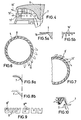
- the gas burner shown partially in section in FIGS. 1, 1a, generally designated 1, has the following structure:
- a burner stand 2 with an injector 20 passes through an indicated gas trough 3.
- the area of the burner stand that projects beyond the gas trough 3 is surrounded by a plug-on attachment 4 onto which a burner ring 5 is mounted, which is shown in part in supervision in FIG. 1.
- the burner is closed off at the top by a burner cover 6, which in the example shown in FIG. 1 is centrally equipped with an inward-pointing flow cone 7.
- the burner ring 5 can be seen to be equipped with a large number of gas outlet channels 8, the central axis of which is indicated by an arrow 9 in FIG Angle to the corresponding radius, designated 10, the angle is designated in Fig. 1a with ⁇ .
- the free outlet end of the gas outlet channels 8 bears the reference symbol 8a.
- Fig. 6 similar to Fig. 1a, the burner ring 5 is shown in plan with indicated flames 11, which are recognizably not directed radially outwards, but have an angle to the radial flow, so that there is a vortex formation.
- the channels 8 shown in FIGS. 6 and 1a are straight there in supervision, in FIG. 7 the possibility is shown to make these channels arcuate.
- channels 8 or 8 ' can be straight or curved when viewed from above, they can have a wide variety of cross-sectional shapes; a selection of these cross-sectional shapes is indicated in FIG. 9.
- channels of circular cross-section can also be provided, this is indicated by 8 ′′ in FIG. 9, or adjacent ones with different cross-sectional sizes, this is indicated by 8 ′′ in FIG. 9.
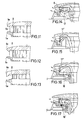
- gas outlet slots or bores can be provided below the gas outlet channels, in order to e.g. to form auxiliary flames at full load, which is indicated in FIG. 2 by an arrow 12, while the gas flow course through the gas outlet channels 8 is designated by 13.
- Fig. 3 it is also shown that additional openings 14 can be provided to suck in secondary air from below the trough 3, which is used for flame cooling, the flow path of this secondary air is designated by 15 in Fig. 3.
- the burner cap is designated 6 throughout, even if it has a cross-sectional shape or edge design that differs from other representations.
- the curved flow cone is designated by 7 (FIG. 8a) and by 7 'in the straight course in the case 8b.
- cooling fins 16 can also be provided in the cover 6, for example, which may have a spiral course for pre-swirling or may also surround the flow cone concentrically, different cross-sectional shapes are shown in FIGS. 5a and 5b.
- 11 to 15 show different configurations of the respective course of the gas outlet channels 8 relative to the free front edge 6a of the burner cover on the one hand and 5a of the burner ring on the other hand relative to the outlet opening 8a.
- FIG. 11 shows a design similar to FIG. 11, but here the transition areas to the free outer edges 6a and 5a are shown diverging, in FIG. 13 there is a converging course.
- FIG. 14 shows a bellows-widening inflow space designated 17 for the gas before entering the gas outlet channels 8.
- FIG. 15 shows an essentially parallel gas flow path 17 ′.
- 16 shows an area 17 ′′ widening from the inside out, which is brought about by a gas guide or deflection body 18 in the interior of the burner.
- a further baffle insert 18 ' is shown in FIG. 17, which in particular optimizes the secondary flame formation.
- FIG. 18 A further exemplary embodiment of the invention is shown in FIG. 18, wherein the parts that are otherwise the same as in FIG. 1 have the same reference numerals, supplemented by a "c".
- the injector 20c is fixed on the stand 2c by means of a clamping ring 21, it being possible for the plug-in attachment 4c to be fixed on the sheet metal of the hob 3c simultaneously with the clamping ring 21.
- the burner is made of three parts from the elements 5c burner ring and 6c burner cover, since an intermediate disk 19 which also provides the flow edge for the gas flame is provided in the front edge region of the burner cover 6c.
- baffle and guide bodies in their cross-sectional shapes also represent examples, such as the designs of the flow guide cone 7, the cooling fins 16 or the special cross-sectional and profile shapes of the channels 8.
Landscapes
- Engineering & Computer Science (AREA)
- Chemical & Material Sciences (AREA)
- Combustion & Propulsion (AREA)
- Mechanical Engineering (AREA)
- General Engineering & Computer Science (AREA)
- Gas Burners (AREA)
- Glass Compositions (AREA)
- Gas Separation By Absorption (AREA)
- Addition Polymer Or Copolymer, Post-Treatments, Or Chemical Modifications (AREA)
- Superconductors And Manufacturing Methods Therefor (AREA)
Applications Claiming Priority (2)
| Application Number | Priority Date | Filing Date | Title |
|---|---|---|---|
| DE4203668A DE4203668A1 (de) | 1992-02-08 | 1992-02-08 | Gasbrenner |
| DE4203668 | 1992-02-08 |
Publications (2)
| Publication Number | Publication Date |
|---|---|
| EP0554511A1 EP0554511A1 (de) | 1993-08-11 |
| EP0554511B1 true EP0554511B1 (de) | 1996-04-10 |
Family
ID=6451239
Family Applications (1)
| Application Number | Title | Priority Date | Filing Date |
|---|---|---|---|
| EP92115875A Expired - Lifetime EP0554511B1 (de) | 1992-02-08 | 1992-09-17 | Gasbrenner |
Country Status (17)
| Country | Link |
|---|---|
| US (1) | US5649822A (cs) |
| EP (1) | EP0554511B1 (cs) |
| JP (1) | JPH06506764A (cs) |
| AT (1) | ATE136633T1 (cs) |
| AU (1) | AU652860B2 (cs) |
| BR (1) | BR9205865A (cs) |
| CA (1) | CA2108020A1 (cs) |
| CZ (1) | CZ9302016A3 (cs) |
| DE (2) | DE4203668A1 (cs) |
| ES (1) | ES2087384T3 (cs) |
| FI (1) | FI934385A7 (cs) |
| GR (1) | GR3019809T3 (cs) |
| HU (1) | HUT67774A (cs) |
| PL (1) | PL300706A1 (cs) |
| SK (1) | SK107693A3 (cs) |
| TR (1) | TR26749A (cs) |
| WO (1) | WO1993016328A1 (cs) |
Families Citing this family (81)
| Publication number | Priority date | Publication date | Assignee | Title |
|---|---|---|---|---|
| WO1995008738A1 (en) * | 1993-09-23 | 1995-03-30 | General Electric Company | Sealed-top gas burner with integrated secondary air supply |
| US6085699A (en) * | 1995-04-04 | 2000-07-11 | Srp 687 Pty Ltd. | Air inlets for water heaters |
| US6155211A (en) * | 1995-04-04 | 2000-12-05 | Srp 687 Pty Ltd. | Air inlets for water heaters |
| US6196164B1 (en) | 1995-04-04 | 2001-03-06 | Srp 687 Pty. Ltd. | Ignition inhibiting gas water heater |
| US5797355A (en) | 1995-04-04 | 1998-08-25 | Srp 687 Pty Ltd | Ignition inhibiting gas water heater |
| US6135061A (en) * | 1995-04-04 | 2000-10-24 | Srp 687 Pty Ltd. | Air inlets for water heaters |
| AU126065S (en) | 1995-06-29 | 1996-03-11 | Ausmark Int Pty Ltd | Burner part |
| IT1277266B1 (it) * | 1995-10-17 | 1997-11-05 | Enrico Sebastiani | Apparecchio a gas per il riscaldamento di fluidi |
| DE19604448A1 (de) * | 1996-02-07 | 1997-08-14 | Cramer Gmbh | Gasbrenner für Kochgeräte |
| US6092518A (en) * | 1996-10-09 | 2000-07-25 | Sourdillon | Cooking appliance, gas burner for this appliance and method for mounting such a gas burner on such appliance |
| WO1998030838A1 (en) * | 1997-01-09 | 1998-07-16 | Robertshaw Controls Company | Variable input gas top burner |
| DE29702649U1 (de) | 1997-02-15 | 1998-06-18 | EGA Engineering GmbH, 58119 Hagen | Gasbrenner für flache Kochmulden |
| US6131561A (en) * | 1998-02-11 | 2000-10-17 | Lincoln Brass Works, Inc. | Burner with secondary air stability ring |
| DE19825896C1 (de) * | 1998-06-10 | 2000-01-05 | Metallwaren Heidersdorf Gmbh | Gasbrenner für Kochstellen |
| US6223697B1 (en) * | 1998-08-21 | 2001-05-01 | Srp 687 Pty Ltd. | Water heater with heat sensitive air inlet |
| US6293230B1 (en) * | 1998-10-20 | 2001-09-25 | Srp 687 Pty Ltd. | Water heaters with flame traps |
| US6227696B1 (en) * | 1999-03-31 | 2001-05-08 | J.H. Horne & Sons Company | Radial diffuser |
| US6146132A (en) * | 1999-08-14 | 2000-11-14 | Harneit; Uwe | Gas burner for outdoor cooking |
| FR2800845B1 (fr) * | 1999-11-10 | 2002-01-25 | Brandt Cooking | Bruleur a gaz pour table de cuisson domestique |
| FR2800846B1 (fr) * | 1999-11-10 | 2002-01-25 | Brandt Cooking | Bruleur a gaz pour table de cuisson domestique |
| US6267586B1 (en) * | 2000-05-05 | 2001-07-31 | Beckett Gas, Inc. | Low NOx burner |
| US6322354B1 (en) | 2000-07-17 | 2001-11-27 | Wolf Appliance Company, Llc | Stacked dual gas burner |
| NZ505833A (en) * | 2000-07-19 | 2002-12-20 | Fisher & Paykel Appliances Ltd | A spiral involute gas burner housing with reconfigurable jet mounted below burner assembly |
| US6607378B2 (en) * | 2000-09-15 | 2003-08-19 | Uwe Harneit | Ignition flame for gas cooking burners |
| US6443103B1 (en) | 2001-08-17 | 2002-09-03 | Srp 687 Pty. Ltd. | Flammable vapor resistant water heater with low NOx emissions |
| US7322820B2 (en) * | 2001-11-08 | 2008-01-29 | Bsh Home Appliances Corporation | Controlled flame gas burner |
| US6446581B1 (en) | 2001-11-16 | 2002-09-10 | Srp 687 Pty. Ltd. | Flammable vapor resistant water heater with low NOx emissions |
| WO2003044428A1 (de) | 2001-11-23 | 2003-05-30 | BSH Bosch und Siemens Hausgeräte GmbH | Gaskochmulde |
| ITPS20030016A1 (it) * | 2003-04-18 | 2004-10-19 | So M I Press Societa Metalli I Niettati Spa | Bruciatore per fornelli a gas, di tipo perfezionato. |
| EP1512908A1 (en) * | 2003-09-05 | 2005-03-09 | Electrolux Home Products Corporation N.V. | Gas burner |
| ES2314151T3 (es) * | 2003-09-05 | 2009-03-16 | Electrolux Home Products Corporation N.V. | Quemador de gas. |
| ITTO20050685A1 (it) * | 2005-09-30 | 2007-04-01 | Indesit Co Spa | Piano di cottura con bruciatore a gas comprendente un elemento semipermeabile |
| USD565893S1 (en) | 2006-12-22 | 2008-04-08 | Electrolux Home Products, Inc. | Portion of a burner assembly |
| USD562069S1 (en) | 2006-12-22 | 2008-02-19 | Electrolux Home Products, Inc. | Portion of a burner assembly |
| USD562070S1 (en) | 2006-12-22 | 2008-02-19 | Electrolux Home Products | Portion of a burner assembly |
| US7628609B2 (en) * | 2006-12-29 | 2009-12-08 | Electrolux Home Products, Inc. | Hub and spoke burner with flame stability |
| US20090078247A1 (en) * | 2007-06-11 | 2009-03-26 | Yizhong Sun | Removable flame heat transfer regulating apparatus including an inner hollow shell and outer wall incorporated with a burner having improved burner ports for a gas stove |
| ES2345311B1 (es) * | 2008-02-29 | 2011-09-16 | Ruixiong Ruan | Quemador para cocina. |
| ES2389998T3 (es) * | 2008-03-25 | 2012-11-05 | Electrolux Home Products Corporation N.V. | Encimera de cocción con quemador de gas mejorado |
| US8616193B2 (en) * | 2008-06-27 | 2013-12-31 | Electrolux Home Products, Inc. | Cooktop swirl burner |
| US8596259B2 (en) * | 2009-01-13 | 2013-12-03 | Electrolux Home Products, Inc. | High efficiency burner |
| US8689779B2 (en) * | 2009-01-23 | 2014-04-08 | Bsh Bosch Und Siemens Hausgeraete Gmbh | Gas burner |
| US20110086318A1 (en) * | 2009-10-09 | 2011-04-14 | American Wyott Corporation | Method and apparatus for maintaining stable flame conditions in a gas burner |
| CN201582887U (zh) * | 2009-11-23 | 2010-09-15 | 惠而浦产品研发(深圳)有限公司 | 火盖及灶头 |
| MX345335B (es) * | 2009-12-18 | 2017-01-25 | Mabe S A De C V * | Quemador de tres sectores de flama. |
| ES2590103T3 (es) * | 2010-10-11 | 2016-11-18 | BSH Hausgeräte GmbH | Quemador de gas para un aparato de cocción |
| ITMI20111471A1 (it) * | 2011-08-01 | 2013-02-02 | Smeg Spa | Bruciatore a gas per un piano di cottura e piano di cottura comprendente tale bruciatore a gas |
| WO2013065018A2 (en) * | 2011-11-03 | 2013-05-10 | Indesit Company S.P.A. | Gas burner, in particular for a cooking appliance |
| ITTO20111003A1 (it) * | 2011-11-03 | 2013-05-04 | Indesit Co Spa | Bruciatore a gas, in particolare per un apparecchio di cottura |
| BRPI1105194A2 (pt) | 2011-12-21 | 2013-11-19 | Whirlpool Sa | Queimador para equipamentos de cocção |
| DE102012206507A1 (de) * | 2012-04-20 | 2013-10-24 | BSH Bosch und Siemens Hausgeräte GmbH | Brenner für ein gasbeheiztes Gargerät |
| WO2014078572A1 (en) * | 2012-11-14 | 2014-05-22 | Biolite Llc | Efficiency pot and kettle for use with cooking stoves |
| CN103292328B (zh) * | 2013-06-13 | 2016-09-28 | 胡端志 | 全燃烧式高效节能燃气炉头 |
| US9541294B2 (en) * | 2013-08-06 | 2017-01-10 | Whirlpool Corporation | Inner swirling flame gas burner |
| MX383153B (es) * | 2014-05-28 | 2025-03-13 | Controladora Mabe Sa De Capital Variable | Quemador de bajo costo. |
| US9791156B2 (en) * | 2014-07-30 | 2017-10-17 | Haier Us Appliance Solutions, Inc. | Elongated burner assembly |
| ES2755373T3 (es) * | 2015-07-23 | 2020-04-22 | Electrolux Appliances AB | Conjunto de quemador de gas para aparato de cocina de gas |
| USD787041S1 (en) | 2015-09-17 | 2017-05-16 | Whirlpool Corporation | Gas burner |
| US10837651B2 (en) | 2015-09-24 | 2020-11-17 | Whirlpool Corporation | Oven cavity connector for operating power accessory trays for cooking appliance |
| JP6635778B2 (ja) * | 2015-12-10 | 2020-01-29 | 大阪瓦斯株式会社 | コンロ用バーナ、及びそれを備えたコンロ |
| US11777190B2 (en) | 2015-12-29 | 2023-10-03 | Whirlpool Corporation | Appliance including an antenna using a portion of appliance as a ground plane |
| US10222070B2 (en) * | 2016-01-15 | 2019-03-05 | Haier Us Appliance Solutions, Inc. | Gas burner assembly with a temperature sensor |
| US10145568B2 (en) | 2016-06-27 | 2018-12-04 | Whirlpool Corporation | High efficiency high power inner flame burner |
| US10436451B2 (en) | 2016-10-06 | 2019-10-08 | Whirlpool Corporation | Cap to change inner flame burner to vertical flame |
| US10627113B2 (en) | 2016-12-29 | 2020-04-21 | Whirlpool Corporation | Distributed vertical flame burner |
| US10551056B2 (en) | 2017-02-23 | 2020-02-04 | Whirlpool Corporation | Burner base |
| US10451290B2 (en) | 2017-03-07 | 2019-10-22 | Whirlpool Corporation | Forced convection steam assembly |
| US10660162B2 (en) | 2017-03-16 | 2020-05-19 | Whirlpool Corporation | Power delivery system for an induction cooktop with multi-output inverters |
| RU177321U1 (ru) * | 2017-07-25 | 2018-02-15 | федеральное государственное бюджетное образовательное учреждение высшего образования "Белгородский государственный технологический университет им. В.Г. Шухова" | Газовая горелка |
| US10344969B2 (en) | 2017-08-03 | 2019-07-09 | Electrolux Home Products, Inc. | Burner assembly |
| US10753617B2 (en) * | 2017-08-16 | 2020-08-25 | Haier Us Appliance Solutions, Inc. | Cooktop appliance with a gas burner assembly |
| CN107726318B (zh) * | 2017-10-17 | 2023-03-10 | 珠海格力电器股份有限公司 | 燃烧器及包括其的燃气灶 |
| DE102017125694B4 (de) | 2017-11-03 | 2019-10-10 | (B)energy GmbH | Brennerkopf für insbesondere einen Gasbrenner |
| US10627116B2 (en) | 2018-06-26 | 2020-04-21 | Whirlpool Corporation | Ventilation system for cooking appliance |
| US10619862B2 (en) | 2018-06-28 | 2020-04-14 | Whirlpool Corporation | Frontal cooling towers for a ventilation system of a cooking appliance |
| US10837652B2 (en) | 2018-07-18 | 2020-11-17 | Whirlpool Corporation | Appliance secondary door |
| US10948181B2 (en) * | 2019-05-22 | 2021-03-16 | Bsh Home Appliances Corporation | Multi-level gas burner having ultra low simmer |
| US11460190B2 (en) * | 2019-07-29 | 2022-10-04 | Haier Us Appliance Solutions, Inc. | Gas burner assembly for a cooktop appliance |
| RU210455U1 (ru) * | 2021-12-21 | 2022-04-15 | федеральное государственное бюджетное образовательное учреждение высшего образования "Белгородский государственный технологический университет им. В.Г. Шухова" | Газовая горелка с коническим рассекателем |
| PL73358Y1 (pl) * | 2022-02-16 | 2024-02-19 | Stalgast Radom Spolka Z Ograniczona Odpowiedzialnoscia | Palnik kuchenny |
| CN115388407B (zh) * | 2022-09-23 | 2025-08-29 | 江苏赛迪能源工程有限公司 | 氢气点火烧嘴及应用该烧嘴的燃烧器 |
Family Cites Families (27)
| Publication number | Priority date | Publication date | Assignee | Title |
|---|---|---|---|---|
| DE88484C (cs) * | ||||
| NL36302C (cs) * | ||||
| DE576000C (de) * | 1933-05-06 | Theodor Wieder | Brennerkopf | |
| US873182A (en) * | 1907-03-12 | 1907-12-10 | Edward S Springer | Gas-burner. |
| DE335942C (de) * | 1919-05-27 | 1921-04-19 | Patent Grudeofen Fabrik Walter | Gasheizbrenner mit zwei oder mehreren Flammenkraenzen und gemeinsamer oder getrennter Gaszufuehrung |
| US1598996A (en) * | 1925-09-05 | 1926-09-07 | Frank H Wheelock | Gas burner |
| FR662339A (fr) * | 1927-10-21 | 1929-08-06 | Maurice Perier | Brûleur |
| FR1234279A (fr) * | 1959-05-14 | 1960-10-17 | Brûleur pour tous gaz | |
| FR1303237A (fr) * | 1961-09-06 | 1962-09-07 | Nouveau brûleur à gaz, de haute sécurité | |
| FR80694E (fr) * | 1961-11-22 | 1963-05-31 | Scholtes Ets Eugen | Brûleur à gaz |
| US3211208A (en) * | 1962-06-04 | 1965-10-12 | Borwick David Harold | Gas burners |
| FR1360192A (fr) * | 1963-01-30 | 1964-05-08 | Procedes Sauter | Brûleur à gaz perfectionné |
| BE645327A (cs) * | 1964-03-17 | 1964-07-16 | ||
| FR1479360A (fr) * | 1966-03-16 | 1967-05-05 | Cepem | Brûleur à gaz à pilotage |
| FR1527971A (fr) * | 1967-04-14 | 1968-06-07 | Colombel Freres Ets | Brûleur extra plat pour gaz basse pression |
| FR2161142A6 (cs) * | 1971-11-15 | 1973-07-06 | Cepem | |
| US3874841A (en) * | 1974-04-19 | 1975-04-01 | Lincoln Brass Works | Gas burner |
| US3905756A (en) * | 1974-05-09 | 1975-09-16 | Lincoln Brass Works | Shutter structure and mixing tube assembly for gas burner |
| US4168950A (en) * | 1975-07-17 | 1979-09-25 | Selas Corporation Of America | Furnace wall construction |
| GB1579322A (en) * | 1977-04-29 | 1980-11-19 | Glynwed Domestic & Heating App | Gas burners |
| SU673817A1 (ru) * | 1977-10-27 | 1980-04-25 | Новогрудский Завод Газовой Аппаратуры | Горелочна насадка |
| JPS5630521A (en) * | 1979-08-21 | 1981-03-27 | Shoei Seisakusho:Kk | Swirl combustion type gas burner |
| JPS5749734A (en) * | 1980-09-09 | 1982-03-23 | Matsushita Electric Ind Co Ltd | Gas cooker |
| IT8406969U1 (it) * | 1984-04-16 | 1985-10-16 | Sabaf Spa | Bruciatore a gas per fornelli e piani di cottura in genere |
| HU196851B (en) * | 1986-03-26 | 1989-01-30 | Magyar Szenhidrogenipari | Premixing gas burner |
| DE3861124D1 (de) * | 1987-09-16 | 1991-01-03 | Parkinson Cowan Appliances Ltd | Gasbrenner. |
| FR2656677B1 (fr) * | 1989-12-29 | 1994-07-29 | Gaz De France | Bruleur a gaz pour table de cuisson, cuisiniere ou analogue. |
-
1992
- 1992-02-08 DE DE4203668A patent/DE4203668A1/de not_active Withdrawn
- 1992-09-15 SK SK1076-93A patent/SK107693A3/sk unknown
- 1992-09-17 BR BR9205865A patent/BR9205865A/pt not_active Application Discontinuation
- 1992-09-17 CA CA002108020A patent/CA2108020A1/en not_active Abandoned
- 1992-09-17 ES ES92115875T patent/ES2087384T3/es not_active Expired - Lifetime
- 1992-09-17 JP JP5500707A patent/JPH06506764A/ja active Pending
- 1992-09-17 CZ CS932016A patent/CZ9302016A3/cs unknown
- 1992-09-17 FI FI934385A patent/FI934385A7/fi not_active Application Discontinuation
- 1992-09-17 DE DE59205966T patent/DE59205966D1/de not_active Expired - Fee Related
- 1992-09-17 US US08/129,156 patent/US5649822A/en not_active Expired - Fee Related
- 1992-09-17 HU HU9302834A patent/HUT67774A/hu unknown
- 1992-09-17 PL PL92300706A patent/PL300706A1/xx unknown
- 1992-09-17 WO PCT/EP1992/002144 patent/WO1993016328A1/de not_active Ceased
- 1992-09-17 EP EP92115875A patent/EP0554511B1/de not_active Expired - Lifetime
- 1992-09-17 AT AT92115875T patent/ATE136633T1/de not_active IP Right Cessation
- 1992-09-17 AU AU25667/92A patent/AU652860B2/en not_active Ceased
- 1992-11-06 TR TR92/1144A patent/TR26749A/xx unknown
-
1996
- 1996-04-30 GR GR960401196T patent/GR3019809T3/el unknown
Also Published As
| Publication number | Publication date |
|---|---|
| GR3019809T3 (en) | 1996-07-31 |
| ATE136633T1 (de) | 1996-04-15 |
| DE4203668A1 (de) | 1993-08-12 |
| EP0554511A1 (de) | 1993-08-11 |
| PL300706A1 (en) | 1994-03-07 |
| ES2087384T3 (es) | 1996-07-16 |
| HU9302834D0 (en) | 1994-01-28 |
| FI934385A0 (fi) | 1993-10-06 |
| WO1993016328A1 (de) | 1993-08-19 |
| AU652860B2 (en) | 1994-09-08 |
| DE59205966D1 (de) | 1996-05-15 |
| AU2566792A (en) | 1993-09-03 |
| JPH06506764A (ja) | 1994-07-28 |
| SK107693A3 (en) | 1994-03-09 |
| US5649822A (en) | 1997-07-22 |
| CZ9302016A3 (en) | 1994-04-13 |
| FI934385L (fi) | 1993-10-06 |
| TR26749A (tr) | 1995-05-15 |
| CA2108020A1 (en) | 1993-08-09 |
| FI934385A7 (fi) | 1993-10-06 |
| BR9205865A (pt) | 1994-07-05 |
| HUT67774A (en) | 1995-04-28 |
Similar Documents
| Publication | Publication Date | Title |
|---|---|---|
| EP0554511B1 (de) | Gasbrenner | |
| EP0309838B1 (de) | Gasbrenner | |
| DE2712564C2 (de) | Brenner für flüssige Brennstoffe | |
| DE3831624A1 (de) | Gasbrenner | |
| EP0268208A2 (de) | Brenner für einen feststoffbefeuerten Kessel | |
| DE2119831A1 (de) | Gasbrenner | |
| DE3542174C1 (en) | Mixing device for oil burners | |
| DE19751008C1 (de) | Gasbrenner für Kochstellen mit Primärluftvormischung | |
| EP0501209B1 (de) | Verbrennungseinrichtung für Heizöl u. dgl. | |
| DE4412185B4 (de) | Brenner für flüssige oder gasförmige Brennstoffe, insbesondere für Öl | |
| DE19519696A1 (de) | Mischeinrichtung für Brenner von Kleinfeuerungsanlagen | |
| EP0786626A1 (de) | Vormischbrenner | |
| DE10237604A1 (de) | Brenner für eine thermische Nachverbrennungsvorrichtung | |
| DE2809415C2 (cs) | ||
| DE1551763C3 (de) | Reihenbrenner für Brenngas niedriger Zündgeschwindigkeit zur Erzeugung quergerichteter Fächerflammen | |
| CH670297A5 (cs) | ||
| EP0190660A2 (de) | Gas-Gebläsebrenner mit geringer Pressung | |
| DE2407484A1 (de) | Flammrohr fuer gasturbinentriebwerke | |
| DE29912362U1 (de) | Blaubrenner für Heizkessel | |
| DE1551763B2 (de) | Reihenbrenner fuer brenngas niedriger zuendgeschwindigkeit zur erzeugung quergerichteter faecherflammen | |
| DE3118011A1 (de) | "gasbrenner, insbesondere fuer kochgeraete fuer haushalt und gewerbe" | |
| DE1242531B (de) | Bunsenbrenner fuer Gasgeraete | |
| DE20019731U1 (de) | Zweikreisbrenner mit Brennerring und Mittenbrenner | |
| DE102007009404B4 (de) | Feuerungseinrichtung | |
| DE20016808U1 (de) | Gasverteiler |
Legal Events
| Date | Code | Title | Description |
|---|---|---|---|
| PUAI | Public reference made under article 153(3) epc to a published international application that has entered the european phase |
Free format text: ORIGINAL CODE: 0009012 |
|
| AK | Designated contracting states |
Kind code of ref document: A1 Designated state(s): AT BE CH DE DK ES FR GB GR IE IT LI NL PT SE |
|
| 17P | Request for examination filed |
Effective date: 19930709 |
|
| 17Q | First examination report despatched |
Effective date: 19940721 |
|
| GRAA | (expected) grant |
Free format text: ORIGINAL CODE: 0009210 |
|
| AK | Designated contracting states |
Kind code of ref document: B1 Designated state(s): AT BE CH DE DK ES FR GB GR IE IT LI NL PT SE |
|
| PG25 | Lapsed in a contracting state [announced via postgrant information from national office to epo] |
Ref country code: IT Free format text: LAPSE BECAUSE OF FAILURE TO SUBMIT A TRANSLATION OF THE DESCRIPTION OR TO PAY THE FEE WITHIN THE PRESCRIBED TIME-LIMIT;WARNING: LAPSES OF ITALIAN PATENTS WITH EFFECTIVE DATE BEFORE 2007 MAY HAVE OCCURRED AT ANY TIME BEFORE 2007. THE CORRECT EFFECTIVE DATE MAY BE DIFFERENT FROM THE ONE RECORDED. Effective date: 19960410 Ref country code: BE Effective date: 19960410 Ref country code: DK Effective date: 19960410 Ref country code: GR Free format text: LAPSE BECAUSE OF FAILURE TO SUBMIT A TRANSLATION OF THE DESCRIPTION OR TO PAY THE FEE WITHIN THE PRESCRIBED TIME-LIMIT Effective date: 19960410 |
|
| REF | Corresponds to: |
Ref document number: 136633 Country of ref document: AT Date of ref document: 19960415 Kind code of ref document: T |
|
| REF | Corresponds to: |
Ref document number: 59205966 Country of ref document: DE Date of ref document: 19960515 |
|
| REG | Reference to a national code |
Ref country code: IE Ref legal event code: FG4D Free format text: 67918 |
|
| GBT | Gb: translation of ep patent filed (gb section 77(6)(a)/1977) |
Effective date: 19960514 |
|
| REG | Reference to a national code |
Ref country code: ES Ref legal event code: BA2A Ref document number: 2087384 Country of ref document: ES Kind code of ref document: T3 |
|
| REG | Reference to a national code |
Ref country code: GR Ref legal event code: FG4A Free format text: 3019809 |
|
| ET | Fr: translation filed | ||
| REG | Reference to a national code |
Ref country code: ES Ref legal event code: FG2A Ref document number: 2087384 Country of ref document: ES Kind code of ref document: T3 |
|
| SC4A | Pt: translation is available |
Free format text: 960415 AVAILABILITY OF NATIONAL TRANSLATION |
|
| GRAH | Despatch of communication of intention to grant a patent |
Free format text: ORIGINAL CODE: EPIDOS IGRA |
|
| PG25 | Lapsed in a contracting state [announced via postgrant information from national office to epo] |
Ref country code: IE Free format text: LAPSE BECAUSE OF NON-PAYMENT OF DUE FEES Effective date: 19960917 Ref country code: AT Effective date: 19960917 Ref country code: GB Effective date: 19960917 |
|
| PG25 | Lapsed in a contracting state [announced via postgrant information from national office to epo] |
Ref country code: SE Effective date: 19960918 Ref country code: ES Free format text: LAPSE BECAUSE OF NON-PAYMENT OF DUE FEES Effective date: 19960918 |
|
| PG25 | Lapsed in a contracting state [announced via postgrant information from national office to epo] |
Ref country code: LI Effective date: 19960930 Ref country code: CH Effective date: 19960930 |
|
| PLBE | No opposition filed within time limit |
Free format text: ORIGINAL CODE: 0009261 |
|
| PG25 | Lapsed in a contracting state [announced via postgrant information from national office to epo] |
Ref country code: NL Effective date: 19970401 |
|
| 26N | No opposition filed | ||
| REG | Reference to a national code |
Ref country code: GR Ref legal event code: MM2A Free format text: 3019809 |
|
| GBPC | Gb: european patent ceased through non-payment of renewal fee |
Effective date: 19960917 |
|
| REG | Reference to a national code |
Ref country code: CH Ref legal event code: PL |
|
| NLV4 | Nl: lapsed or anulled due to non-payment of the annual fee |
Effective date: 19970401 |
|
| EUG | Se: european patent has lapsed |
Ref document number: 92115875.4 |
|
| PG25 | Lapsed in a contracting state [announced via postgrant information from national office to epo] |
Ref country code: FR Effective date: 19970630 |
|
| REG | Reference to a national code |
Ref country code: FR Ref legal event code: ST |
|
| REG | Reference to a national code |
Ref country code: FR Ref legal event code: ST |
|
| PG25 | Lapsed in a contracting state [announced via postgrant information from national office to epo] |
Ref country code: PT Free format text: LAPSE BECAUSE OF NON-PAYMENT OF DUE FEES Effective date: 19980331 |
|
| REG | Reference to a national code |
Ref country code: PT Ref legal event code: MM4A Free format text: LAPSE DUE TO NON-PAYMENT OF FEES Effective date: 19980331 |
|
| PGFP | Annual fee paid to national office [announced via postgrant information from national office to epo] |
Ref country code: DE Payment date: 20000816 Year of fee payment: 9 |
|
| PG25 | Lapsed in a contracting state [announced via postgrant information from national office to epo] |
Ref country code: DE Free format text: LAPSE BECAUSE OF NON-PAYMENT OF DUE FEES Effective date: 20020501 |
|
| REG | Reference to a national code |
Ref country code: ES Ref legal event code: FD2A Effective date: 19971011 |
|
| PG25 | Lapsed in a contracting state [announced via postgrant information from national office to epo] |
Ref country code: PT Free format text: LAPSE BECAUSE OF NON-PAYMENT OF DUE FEES Effective date: 19960917 |