EP0545375A2 - Ensemble de filage auto-obturant - Google Patents
Ensemble de filage auto-obturant Download PDFInfo
- Publication number
- EP0545375A2 EP0545375A2 EP92120531A EP92120531A EP0545375A2 EP 0545375 A2 EP0545375 A2 EP 0545375A2 EP 92120531 A EP92120531 A EP 92120531A EP 92120531 A EP92120531 A EP 92120531A EP 0545375 A2 EP0545375 A2 EP 0545375A2
- Authority
- EP
- European Patent Office
- Prior art keywords
- seal
- nozzle
- pressure piece
- pot
- channel
- Prior art date
- Legal status (The legal status is an assumption and is not a legal conclusion. Google has not performed a legal analysis and makes no representation as to the accuracy of the status listed.)
- Granted
Links
Images


Classifications
-
- D—TEXTILES; PAPER
- D01—NATURAL OR MAN-MADE THREADS OR FIBRES; SPINNING
- D01D—MECHANICAL METHODS OR APPARATUS IN THE MANUFACTURE OF ARTIFICIAL FILAMENTS, THREADS, FIBRES, BRISTLES OR RIBBONS
- D01D4/00—Spinnerette packs; Cleaning thereof
- D01D4/02—Spinnerettes
-
- D—TEXTILES; PAPER
- D01—NATURAL OR MAN-MADE THREADS OR FIBRES; SPINNING
- D01D—MECHANICAL METHODS OR APPARATUS IN THE MANUFACTURE OF ARTIFICIAL FILAMENTS, THREADS, FIBRES, BRISTLES OR RIBBONS
- D01D4/00—Spinnerette packs; Cleaning thereof
- D01D4/08—Supporting spinnerettes or other parts of spinnerette packs
Definitions
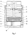
- the invention relates to a self-sealing nozzle packet for a spinning head of a spinning machine for spinning endless thread from a viscous spinning liquid under high pressure, consisting of a nozzle pot, in which a nozzle plate is inserted and covered by a filter packet, a piston-like pressure piece that can move axially in the nozzle pot central channel, the upper surface of which adjoins the lower surface of a distributor block which has at least one channel, an upper seal between the pressure piece and the distributor block, a middle seal for sealing the space above the filter pack from the nozzle cup and a lower flat one Ring seal to seal the nozzle cup downwards.
- Such a self-sealing nozzle package and its mode of operation are known from EP-A2-0 300 120 and EP-B1-0 163 248.
- This known nozzle package can also have a distributor plate (perforated plate) between the nozzle plate and the filter package, which is pot-like at the top is designed to hold the filter package (EP-B1-0 163 248; Item 27).
- this known nozzle package has three, two of which are inadequate seals, one of which, the metal membrane seal, is relatively expensive.
- Another disadvantage was that a relatively large free space was formed by the membrane seal below it, which led to an undesirably long dwell time of the spinning liquid, especially at low thread titers, which resulted in an undesirable change in the same, polymer degradation and the like.
- the present invention was therefore based on the object of providing a generic self-sealing nozzle package which no longer has the disadvantages mentioned above and which is particularly reliable no longer has, which is particularly reliable self-sealing and thus more reliable, which is simpler in construction and therefore cheaper and which has a smaller free space above the filter pack, which leads to a reduction in the dwell time of the spinning liquid in this area.
- Part of the task was to be able to increase the filter area of the filter pack even when using a distributor plate (perforated plate).
- the upper seal is tubular, has an inner diameter which corresponds to the diameter of the central channel of the pressure piece or the channel of the distributor block, and extends into both channels, that the upper surface of the pressure piece is firmly attached to the lower surface of the distributor block under operating conditions, that the pressure piece is designed in a pot-like manner downwards for receiving the filter pack and possibly a distributor plate and that the middle seal is also tubular and the annular gap between the nozzle pot and covers and seals the edge of the pot-like configuration of the pressure piece.
- the solution principle on which the invention is based consists in designing the pressure piece movable in the nozzle pot in such a way that annular gaps are formed at the top between the pressure piece and the distributor block and between the pressure piece and the nozzle pot or the distributor plate at the bottom, which initially extend radially from the inside to the outside , the width of the annular gaps (gap width) possibly changing during operational use, and that this Annular gaps are each covered with a tubular seal, so that the seals are pressed radially outward onto the annular gap by the pressurized spinning liquid and thus bring about a fluid-tight seal.
- the middle, tubular seal is the upward and / or downward leg of a seal with an L-shaped cross section (angled seal).
- the middle, tubular seal that is also the angled seal, is arranged above the nozzle plate, the upper part of the seal or the upwardly pointing leg of the angled seal extending into the pot-like configuration of the pressure piece, i.e. into the pot-like configuration of the pressure piece protrudes.
- An important aspect of the invention is that the sealing effect of the upper and middle, tubular seals, or the upward and / or downward leg of the angular seal, is achieved in that the seals by the high pressure of the spinning liquid (for example 50 to 80 bar) are pushed radially outwards and slightly expanded.
- the membrane seal is no longer necessary and when using an angled seal only two instead of three seals are required, as the upward and / or downward leg of the angled seal performs the sealing function of the membrane seal. This also means that the space above the filter package can now be dimensioned much smaller. The resulting advantage, namely shorter residence time of the spinning liquid, has already been explained.
- the self-sealing effect takes place in the nozzle package according to the invention in the same way as in the known one.
- the pressure builds up in the space above the filter pack, there is a slight movement of the pressure piece within the nozzle cup by only a few tenths of a millimeter up until the upper surface of the pressure piece lies firmly against the lower surface of the distributor block.
- the pressure acts downwards in such a way that the filter pack or - if available - the distributor plate (perforated plate) or the nozzle plate is pressed onto the lower, flat ring seal, which in the case of an angular seal is formed by the radially inward leg of the angular seal becomes.
- the optionally usable perforated plate is not pot-shaped at the top, but is also flat at the top. This leads to a significant increase in the filter area of the filter pack, which can be, for example, approximately 25%, since the outer diameter of the filter pack corresponds to the inner diameter of the nozzle cup in the lower region.
- the filter pack can have the usual means corresponding to the state of the art, such as sieves with different mesh sizes, filter granules, for example sand, with different grain sizes, disks made of sintered materials, etc.
- the distributor plate is expediently provided with a narrow border at the top, the height of which corresponds to the bed height of the filter granulate layer.
- Its design with regard to structure, height, selection of filter media, etc. depends on the type of viscous spinning liquid, which is the melt of thermoplastic polymers such as polyester, polyamide, etc., a solution, such as polyacrylonitrile in solution with DMF, and others can act.
- soft aluminum has proven to be the best material for the seals, but soft iron and other easily deformable materials are also suitable. Suitable materials are those that can withstand the high temperatures of the spinning liquid, which can be up to 450 ° C, for example, in the case of polymer melts.
- the central channel in the pressure piece can have the same diameter or cross-section over its entire length, but can also have a diameter or cross-section that widens or decreases in the direction of flow, that is to say it has a conical shape.
- a mixing element preferably a so-called static mixer, can be arranged in the channel of the pressure piece.
- the nozzle pot can be attached to the distributor block using conventional means such as screws or in some other way.
- this has proven to be particularly advantageous known connection with the help of a multiple thread, which is arranged on the outer circumference of the lower part of the distributor block and as a cooperating counterpart on the inner circumference of the upper part of the nozzle pot. It is possible to achieve a sufficient permanent attachment of the nozzle cup with a rotation of only 180 ° or at most 360 ° of the same. It is important to dimension the pitch of the thread so small that self-locking against loosening of this screw connection is achieved. Otherwise, another protection against rotation, for example a locking pin, must be provided.
- the shape and dimensions of the nozzle package and its parts are not subject to any restrictions - neither upwards nor downwards - and are adapted to the respective requirements.
- Another significant advantage of the nozzle package according to the invention is that its self-sealing effect always occurs reliably even after repeated complete - intentional or unwanted - pressure drop or pressure reduction.
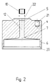
- FIG. 2 an embodiment of the pressure piece 4 is shown.
- the parts 5; 6; 7; 10; 12 and 20, which have already been explained above for FIG. 1, are not listed and described again here.
- 21 designates one of three bores, for example, which make it easier to fix the pressure piece 4 while inserting the filter pack (3) and possibly the distributor plate (11) by means of a corresponding number of pins arranged on a base.
- the pressure piece 4 is reversed around, so with the surface 5 down.
- the channel 12 has in its upper end section the extension 22 for receiving the lower part of the seal 10.
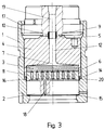
- FIG. 3 differs from the embodiment shown in FIG. 1 only in that the central, tubular seal 14 and the lower, flat seal 15 are not part of an angular seal.
- the lower, flat seal 15 is arranged below the nozzle plate 2. Since all other parts are identical to the parts shown in Figure 1, a further description of this embodiment is omitted.
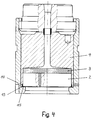
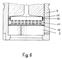
- FIGS. 4 to 7 essentially differ only in the design of the pressure piece 4 and, if present, the perforated plate 11 and the design and arrangement of the seals 14 and 15. All other parts are therefore only provided with item numbers. if they are mentioned in the description below. In Figures 5 to 7, the upper parts and the filter pack (3) are also omitted. A further description of these figures than the following is unnecessary with regard to the description of FIGS. 1 to 3.
- FIG. 4 shows an embodiment in which no distributor plate (11) is used, so that the filter pack 3 lies directly on the nozzle plate 2.
- the middle, tubular seal 14 and the lower, flat seal 15 are again formed by the legs of an angular seal 13. In this embodiment, this is arranged below the nozzle plate 2.
- the middle, tubular seal 14 is arranged above the distributor plate 11, the lower, flat seal 15 between the distributor plate 11 and the nozzle plate 2.
- the distributor plate 11 is not flat at the top, but rather pot-like - for example for receiving of filter granules such as sand or the like. - educated.
- the middle, tubular seal 14 protrudes into the pot-like part of the distributor plate 11 and the pressure piece 4 and lies against the inner surface of the "pot rim".
- annular gap 16 between the lower edge of the pot-like design of the pressure piece 4 and the upper edge of the pot-like design of the distributor plate 11, which is covered by the central, tubular seal 14, can be clearly seen, even if it is caused by the movement of the pressure piece 4 upwards, for example to double the width.
- FIG. 6 corresponds essentially to that shown in Figure 5, but here the central tubular seal 14 is arranged in an annular groove, which is at the lower end of the pot-like design of the pressure piece 4 and at the upper end of the pot-like design of the distributor plate 11 is arranged.
- FIG. 8 shows a double angular seal in longitudinal section, through which the central, tubular seal 14 is formed both by the legs 14a and 14b pointing upwards and downwards.
- the lower, flat seal 15 is also formed here, as in the case of a simple angular seal, by the leg pointing inwards.
Applications Claiming Priority (2)
| Application Number | Priority Date | Filing Date | Title |
|---|---|---|---|
| DE4140269 | 1991-12-06 | ||
| DE4140269 | 1991-12-06 |
Publications (3)
| Publication Number | Publication Date |
|---|---|
| EP0545375A2 true EP0545375A2 (fr) | 1993-06-09 |
| EP0545375A3 EP0545375A3 (en) | 1993-12-08 |
| EP0545375B1 EP0545375B1 (fr) | 1995-11-15 |
Family
ID=6446445
Family Applications (1)
| Application Number | Title | Priority Date | Filing Date |
|---|---|---|---|
| EP92120531A Expired - Lifetime EP0545375B1 (fr) | 1991-12-06 | 1992-12-02 | Ensemble de filage auto-obturant |
Country Status (6)
| Country | Link |
|---|---|
| US (1) | US5387097A (fr) |
| EP (1) | EP0545375B1 (fr) |
| KR (1) | KR930013231A (fr) |
| CN (1) | CN1031655C (fr) |
| DE (2) | DE4236570A1 (fr) |
| TW (1) | TW224147B (fr) |
Cited By (2)
| Publication number | Priority date | Publication date | Assignee | Title |
|---|---|---|---|---|
| WO2001009413A1 (fr) * | 1999-07-30 | 2001-02-08 | Lurgi Zimmer Ag | Filiere compacte auto-etanche pour procede de filage a fusion |
| WO2003066940A1 (fr) * | 2002-02-08 | 2003-08-14 | Zimmer Ag | Porte-buse destine a la fabrication de fils et fibres synthetiques |
Families Citing this family (16)
| Publication number | Priority date | Publication date | Assignee | Title |
|---|---|---|---|---|
| DE19643425C2 (de) * | 1996-10-22 | 1999-12-02 | Geb Schroeder Beeck | Sandlose Spinndüse |
| DE19821406A1 (de) * | 1998-05-13 | 1999-11-18 | Lurgi Zimmer Ag | Abdichtungselement für Schmelzekanäle |
| KR100302319B1 (ko) * | 1999-07-06 | 2001-09-22 | 홍덕희 | 열용융 방사장치의 노즐팩 구조 |
| DE10014292B4 (de) * | 2000-03-23 | 2008-04-03 | Lurgi Zimmer Gmbh | Selbstdichtende Sandfilterdüse |
| JP2005504191A (ja) * | 2001-09-28 | 2005-02-10 | ザウラー ゲゼルシャフト ミット ベシュレンクテル ハフツング ウント コンパニー コマンディートゲゼルシャフト | 紡糸ノズル |
| DE10160204B4 (de) * | 2001-12-07 | 2006-01-26 | Zimmer Ag | Düsenblock mit einer Stützplatte |
| DE10314294A1 (de) | 2003-03-29 | 2004-10-07 | Saurer Gmbh & Co. Kg | Vorrichtung zum Schmelzspinnen |
| CN100368606C (zh) * | 2005-11-14 | 2008-02-13 | 中国石化仪征化纤股份有限公司 | 螺栓紧固式高产能紧凑上装式纺丝组件 |
| DE102007034092A1 (de) | 2007-07-21 | 2009-01-22 | Oerlikon Textile Gmbh & Co. Kg | Schmelzspinnvorrichtung |
| JP5452243B2 (ja) * | 2010-01-19 | 2014-03-26 | Tmtマシナリー株式会社 | 溶融紡糸装置の紡糸パック |
| DE102013014568A1 (de) | 2012-09-26 | 2014-03-27 | Oerlikon Textile Gmbh & Co. Kg | Düsenpaket zum Schmelzspinnen |
| DE102014000305A1 (de) * | 2014-01-10 | 2015-07-16 | Oerlikon Textile Gmbh & Co. Kg | Spinndüsenvorrichtung |
| CN108411387A (zh) * | 2018-04-20 | 2018-08-17 | 中国纺织科学研究院有限公司 | 熔体纺丝设备 |
| CN109234824B (zh) * | 2018-09-20 | 2020-03-03 | 深圳市恩裳纺织品有限公司 | 一种再生聚酯纤维纺丝工艺 |
| CN108866663B (zh) * | 2018-09-20 | 2020-01-21 | 杭州金象纺织有限公司 | 一种再生聚酯纤维纺丝装置 |
| CN115233321A (zh) * | 2021-04-23 | 2022-10-25 | 江苏金斗重工有限公司 | 一种莱赛尔纤维纺丝机熔体分配梁 |
Citations (7)
| Publication number | Priority date | Publication date | Assignee | Title |
|---|---|---|---|---|
| US3353211A (en) * | 1965-01-06 | 1967-11-21 | American Enka Corp | Spinneret assembly |
| DE1660209A1 (de) * | 1965-07-15 | 1970-02-05 | Barmag Barmer Maschf | Schmelzespinnkopf fuer das Spinnen unter hohem Druck |
| US4494921A (en) * | 1983-08-08 | 1985-01-22 | E. I. Du Pont De Nemours And Company | Filter element |
| JPS60119208A (ja) * | 1983-11-28 | 1985-06-26 | Toray Ind Inc | 溶融紡糸用口金パツク |
| EP0163248A2 (fr) * | 1984-05-26 | 1985-12-04 | B a r m a g AG | Bloc de filage pour le filage au fondu de fibres synthétiques |
| EP0300120A2 (fr) * | 1983-03-23 | 1989-01-25 | B a r m a g AG | Filière pour le filage au fondu de filaments |
| EP0436105A2 (fr) * | 1989-11-27 | 1991-07-10 | Barmag Ag | Dispositif de filage |
Family Cites Families (25)
| Publication number | Priority date | Publication date | Assignee | Title |
|---|---|---|---|---|
| DE155090C (fr) * | ||||
| US3123858A (en) * | 1964-03-10 | Heated | ||
| GB755954A (en) * | 1953-08-28 | 1956-08-29 | Ici Ltd | Melt-spinning method and apparatus |
| DE1250961B (fr) * | 1956-05-14 | 1967-09-28 | ||
| US3050774A (en) * | 1957-09-03 | 1962-08-28 | Du Pont | Spinneret assembly |
| US3028627A (en) * | 1959-04-10 | 1962-04-10 | Du Pont | Spinneret pack assembly |
| US3237245A (en) * | 1962-10-10 | 1966-03-01 | Mitsubishi Vonnel Co Ltd | Apparatus for the production of conjugated artificial filaments |
| GB1079295A (en) * | 1964-06-03 | 1967-08-16 | Ici Ltd | Improvements in or relating to the melt-spinning of synthetic linear polymers |
| CH432711A (de) * | 1965-03-03 | 1967-03-31 | Inventa Ag | Vorrichtung zum Spinnen von Fäden aus synthetischem Material |
| CH445840A (de) * | 1966-04-09 | 1967-10-31 | Barmag Barmer Maschf | Vorrichtung an einer Strangpresse zum Abdichten der Anschlussstelle zwischen einem Zuführorgan und einem Werkzeug oder Werkzeugfutter |
| NL6703657A (fr) * | 1967-03-09 | 1968-09-10 | ||
| US3466703A (en) * | 1967-08-11 | 1969-09-16 | Du Pont | Spinneret assembly |
| US3762854A (en) * | 1970-04-08 | 1973-10-02 | Akzona Inc | Melt spinning apparatus |
| DE2250837A1 (de) * | 1972-10-17 | 1974-05-02 | Zimmer Ag | Spinnvorrichtung fuer das ausspinnen hochviskoser spinnmassen |
| US4197020A (en) * | 1972-11-30 | 1980-04-08 | E. I. Du Pont De Nemours And Company | Spinning pack containing mixing means |
| US4134954A (en) * | 1975-07-19 | 1979-01-16 | Bayer Aktiengesellschaft | Spinning process and device with static mixing inserts |
| US4260350A (en) * | 1980-04-16 | 1981-04-07 | Fiber Industries, Inc. | Filter for high viscosity liquids |
| DD155090A1 (de) * | 1980-12-08 | 1982-05-12 | Reinhard Wagner | Spinnduesenpaket zur erspinnung von faeden,insbesondere zum schmelzspinnen von synthetischen hochpolymeren |
| US4493628A (en) * | 1982-07-15 | 1985-01-15 | Barmag Barmer Maschinenfabrik Ag | Melt spinning apparatus |
| US4696633A (en) * | 1984-05-26 | 1987-09-29 | Barmag Ag | Melt spinning apparatus |
| DE3642867A1 (de) * | 1986-12-16 | 1988-06-30 | Barmag Barmer Maschf | Spinnanlage |
| EP0387470B1 (fr) * | 1989-03-17 | 1994-06-08 | Karl Fischer Industrieanlagen Gmbh | Dispositif pour le filage de matières thermoplastiques fondues |
| DE3915819A1 (de) * | 1989-05-16 | 1990-11-22 | Akzo Gmbh | Garn aus kern-mantel-faeden und verfahren zu dessen herstellung |
| GB9010024D0 (en) * | 1990-05-03 | 1990-06-27 | Pall Corp | Filters for polymer spinnerets and their manufacture |
| DE4239560C2 (de) * | 1992-11-25 | 2003-04-30 | Zimmer Ag | Düsenblock |
-
1992
- 1992-10-29 DE DE4236570A patent/DE4236570A1/de not_active Withdrawn
- 1992-11-30 KR KR1019920022800A patent/KR930013231A/ko not_active Application Discontinuation
- 1992-12-02 DE DE59204347T patent/DE59204347D1/de not_active Expired - Fee Related
- 1992-12-02 EP EP92120531A patent/EP0545375B1/fr not_active Expired - Lifetime
- 1992-12-05 CN CN92114129A patent/CN1031655C/zh not_active Expired - Fee Related
- 1992-12-07 US US07/986,298 patent/US5387097A/en not_active Expired - Fee Related
-
1993
- 1993-01-14 TW TW082100197A patent/TW224147B/zh active
Patent Citations (7)
| Publication number | Priority date | Publication date | Assignee | Title |
|---|---|---|---|---|
| US3353211A (en) * | 1965-01-06 | 1967-11-21 | American Enka Corp | Spinneret assembly |
| DE1660209A1 (de) * | 1965-07-15 | 1970-02-05 | Barmag Barmer Maschf | Schmelzespinnkopf fuer das Spinnen unter hohem Druck |
| EP0300120A2 (fr) * | 1983-03-23 | 1989-01-25 | B a r m a g AG | Filière pour le filage au fondu de filaments |
| US4494921A (en) * | 1983-08-08 | 1985-01-22 | E. I. Du Pont De Nemours And Company | Filter element |
| JPS60119208A (ja) * | 1983-11-28 | 1985-06-26 | Toray Ind Inc | 溶融紡糸用口金パツク |
| EP0163248A2 (fr) * | 1984-05-26 | 1985-12-04 | B a r m a g AG | Bloc de filage pour le filage au fondu de fibres synthétiques |
| EP0436105A2 (fr) * | 1989-11-27 | 1991-07-10 | Barmag Ag | Dispositif de filage |
Non-Patent Citations (2)
| Title |
|---|
| & JP-A-60 119 208 (TORAY KK) 26. Juni 1985 * |
| PATENT ABSTRACTS OF JAPAN vol. 9, no. 271 (C-311)29. Oktober 1985 & JP-A-60 119 208 ( TORAY KK ) 26. Juni 1985 * |
Cited By (2)
| Publication number | Priority date | Publication date | Assignee | Title |
|---|---|---|---|---|
| WO2001009413A1 (fr) * | 1999-07-30 | 2001-02-08 | Lurgi Zimmer Ag | Filiere compacte auto-etanche pour procede de filage a fusion |
| WO2003066940A1 (fr) * | 2002-02-08 | 2003-08-14 | Zimmer Ag | Porte-buse destine a la fabrication de fils et fibres synthetiques |
Also Published As
| Publication number | Publication date |
|---|---|
| EP0545375B1 (fr) | 1995-11-15 |
| DE59204347D1 (de) | 1995-12-21 |
| DE4236570A1 (fr) | 1993-06-09 |
| US5387097A (en) | 1995-02-07 |
| CN1031655C (zh) | 1996-04-24 |
| CN1077505A (zh) | 1993-10-20 |
| EP0545375A3 (en) | 1993-12-08 |
| TW224147B (fr) | 1994-05-21 |
| KR930013231A (ko) | 1993-07-21 |
Similar Documents
| Publication | Publication Date | Title |
|---|---|---|
| EP0545375B1 (fr) | Ensemble de filage auto-obturant | |
| DE3024108C2 (fr) | ||
| DE1946220U (de) | Dichtungsring. | |
| DE19546440A1 (de) | Filtervorrichtung mit Bypaßventil | |
| DE3113624A1 (de) | "rueckspuelbare filtriervorrichtung" | |
| EP0379054B1 (fr) | Dispositif filtrant | |
| EP0658638B1 (fr) | Tête à filer avec bougie filtrante | |
| DE202006001793U1 (de) | Stützkörper für Filterelemente und Filterelement hiermit | |
| DE19859960B4 (de) | Flüssigkeitsfilter | |
| DE2462474A1 (de) | Sprinklerkopf fuer ein sprinklersystem | |
| DE1912631B2 (de) | Geschlitzter Kolbenring | |
| DE4239560A1 (de) | Spinnblock | |
| DE19545791C2 (de) | Filtertrockner, insbesondere Groß-Filtertrockner, für stationäre Kälteanlagen, sowie Filtertrocknerkartusche zur Verwendung bei einem solchen Filtertrockner | |
| DE19905378C1 (de) | Filtertrockner, insbesondere Groß-Filtertrockner, für stationäre Kälteanlagen sowie Filtertrocknerkartusche zur Verwendung bei einem solchen Filtertrockner | |
| DE2548504A1 (de) | Einrichtung zum befestigen eines drehknopfes an einer welle | |
| DE2854830C2 (de) | Röhrendruckfilter | |
| EP1247635A2 (fr) | Dispositif de filtration de matière plastique fluide | |
| EP1440188B1 (fr) | Filiere | |
| DE4124221C3 (de) | Dichtring | |
| DE10014292B4 (de) | Selbstdichtende Sandfilterdüse | |
| DE2734695C2 (de) | Bleistiftspitzer mit Spänebehälter und staubdicht aufsitzendem Verschlußstopfen | |
| DE3326288A1 (de) | Filterkerze fuer filtervorrichtung | |
| DE3109481C2 (de) | Zylindrische Filterhülse, insbesondere für Hochdruckfilter | |
| DE2227378B2 (de) | Filtersatz | |
| DE2608647C3 (de) | Abdichtung für kolbenartige hydrostatische Stützelemente einer Durchbiegungseinstellwalze |
Legal Events
| Date | Code | Title | Description |
|---|---|---|---|
| PUAI | Public reference made under article 153(3) epc to a published international application that has entered the european phase |
Free format text: ORIGINAL CODE: 0009012 |
|
| AK | Designated contracting states |
Kind code of ref document: A2 Designated state(s): CH DE FR GB IT LI |
|
| PUAL | Search report despatched |
Free format text: ORIGINAL CODE: 0009013 |
|
| AK | Designated contracting states |
Kind code of ref document: A3 Designated state(s): CH DE FR GB IT LI |
|
| 17P | Request for examination filed |
Effective date: 19931105 |
|
| RAP1 | Party data changed (applicant data changed or rights of an application transferred) |
Owner name: AKZO NOBEL N.V. |
|
| 17Q | First examination report despatched |
Effective date: 19950411 |
|
| GRAA | (expected) grant |
Free format text: ORIGINAL CODE: 0009210 |
|
| ITF | It: translation for a ep patent filed |
Owner name: BARZANO' E ZANARDO ROMA S.P.A. |
|
| AK | Designated contracting states |
Kind code of ref document: B1 Designated state(s): CH DE FR GB IT LI |
|
| ET | Fr: translation filed | ||
| REF | Corresponds to: |
Ref document number: 59204347 Country of ref document: DE Date of ref document: 19951221 |
|
| GBT | Gb: translation of ep patent filed (gb section 77(6)(a)/1977) |
Effective date: 19960108 |
|
| PLBE | No opposition filed within time limit |
Free format text: ORIGINAL CODE: 0009261 |
|
| STAA | Information on the status of an ep patent application or granted ep patent |
Free format text: STATUS: NO OPPOSITION FILED WITHIN TIME LIMIT |
|
| 26N | No opposition filed | ||
| PGFP | Annual fee paid to national office [announced via postgrant information from national office to epo] |
Ref country code: FR Payment date: 19981029 Year of fee payment: 7 |
|
| PGFP | Annual fee paid to national office [announced via postgrant information from national office to epo] |
Ref country code: CH Payment date: 19981030 Year of fee payment: 7 |
|
| PGFP | Annual fee paid to national office [announced via postgrant information from national office to epo] |
Ref country code: GB Payment date: 19981102 Year of fee payment: 7 |
|
| PGFP | Annual fee paid to national office [announced via postgrant information from national office to epo] |
Ref country code: DE Payment date: 19981110 Year of fee payment: 7 |
|
| PG25 | Lapsed in a contracting state [announced via postgrant information from national office to epo] |
Ref country code: GB Free format text: LAPSE BECAUSE OF NON-PAYMENT OF DUE FEES Effective date: 19991202 |
|
| PG25 | Lapsed in a contracting state [announced via postgrant information from national office to epo] |
Ref country code: LI Free format text: LAPSE BECAUSE OF NON-PAYMENT OF DUE FEES Effective date: 19991231 Ref country code: CH Free format text: LAPSE BECAUSE OF NON-PAYMENT OF DUE FEES Effective date: 19991231 |
|
| GBPC | Gb: european patent ceased through non-payment of renewal fee |
Effective date: 19991202 |
|
| PG25 | Lapsed in a contracting state [announced via postgrant information from national office to epo] |
Ref country code: FR Free format text: LAPSE BECAUSE OF NON-PAYMENT OF DUE FEES Effective date: 20000831 |
|
| PG25 | Lapsed in a contracting state [announced via postgrant information from national office to epo] |
Ref country code: DE Free format text: LAPSE BECAUSE OF NON-PAYMENT OF DUE FEES Effective date: 20001003 |
|
| REG | Reference to a national code |
Ref country code: FR Ref legal event code: ST |
|
| PG25 | Lapsed in a contracting state [announced via postgrant information from national office to epo] |
Ref country code: IT Free format text: LAPSE BECAUSE OF NON-PAYMENT OF DUE FEES;WARNING: LAPSES OF ITALIAN PATENTS WITH EFFECTIVE DATE BEFORE 2007 MAY HAVE OCCURRED AT ANY TIME BEFORE 2007. THE CORRECT EFFECTIVE DATE MAY BE DIFFERENT FROM THE ONE RECORDED. Effective date: 20051202 |