EP0163248A2 - Bloc de filage pour le filage au fondu de fibres synthétiques - Google Patents
Bloc de filage pour le filage au fondu de fibres synthétiques Download PDFInfo
- Publication number
- EP0163248A2 EP0163248A2 EP85106256A EP85106256A EP0163248A2 EP 0163248 A2 EP0163248 A2 EP 0163248A2 EP 85106256 A EP85106256 A EP 85106256A EP 85106256 A EP85106256 A EP 85106256A EP 0163248 A2 EP0163248 A2 EP 0163248A2
- Authority
- EP
- European Patent Office
- Prior art keywords
- heating jacket
- nozzle
- melt
- pump block
- spinning
- Prior art date
- Legal status (The legal status is an assumption and is not a legal conclusion. Google has not performed a legal analysis and makes no representation as to the accuracy of the status listed.)
- Granted
Links
Images


Classifications
-
- D—TEXTILES; PAPER
- D01—NATURAL OR MAN-MADE THREADS OR FIBRES; SPINNING
- D01D—MECHANICAL METHODS OR APPARATUS IN THE MANUFACTURE OF ARTIFICIAL FILAMENTS, THREADS, FIBRES, BRISTLES OR RIBBONS
- D01D4/00—Spinnerette packs; Cleaning thereof
- D01D4/06—Distributing spinning solution or melt to spinning nozzles
-
- D—TEXTILES; PAPER
- D01—NATURAL OR MAN-MADE THREADS OR FIBRES; SPINNING
- D01D—MECHANICAL METHODS OR APPARATUS IN THE MANUFACTURE OF ARTIFICIAL FILAMENTS, THREADS, FIBRES, BRISTLES OR RIBBONS
- D01D4/00—Spinnerette packs; Cleaning thereof
Definitions
- the invention relates to a spinning beam for extrusion, in particular melt spinning synthetic threads according to the preamble of claim 1.
- Such a spinning beam (compare DE-AS 19 08 207) consists of a double-walled heating jacket, which is designed to hold a particularly vaporous heating medium as a pressure vessel and in its interior open chambers with plane-parallel machined heating surfaces for receiving and heat-conducting connection of melt-carrying components, such as pump blocks, metering pumps and optionally heat-conducting blocks.
- the heating jacket of the spinning beam is housed in a housing and surrounded by thermal insulation.
- melt-carrying components lie on a double-walled heating plate, which can be flat or L-shaped or U-shaped in cross-section and is supplemented by applied, heat-conducting fillers to form a closed hollow beam. All melt-carrying components can only be used from above, for which the insulating pieces and the corresponding fillers have to be removed. Between the insulating bodies and the packing may occur due to manufacturing tolerances and different thermal expansions, more or less there are wide gaps through which as a result of K amine effectively uncontrolled heat can flow. This can lead to different heating of the melt at the different spinning positions of the spinning beam.
- the object is achieved by a spinning beam with the features specified in the characterizing part of claim 1.
- the specified solution offers the advantages of a very uniform and inexpensive heating of all melt-carrying components and avoids vertical separating joints within the parts of the heating jacket and the thermal insulation.
- the chamber formed between the outer, horizontal U-legs of the heating jacket, which is U-shaped in cross section, for receiving the melt-carrying components is closed off from the nozzle shafts built into the heating jacket, and the chamber is sealed from the side (reduction of the overall height ) or accessible from above, while the nozzle pots with the pre-assembled nozzle packages are installed through the nozzle shafts in the heating jacket.
- a working platform above the spinning beam can be omitted if this is desirable.
- a connecting plug in particular with an external thread or bayonet lock for connecting the nozzle pot receiving the nozzle packet, is pressure-tightly connected to the pump block, in particular is screwed to or connected to the pump block forms a component.
- the development according to claim 3 has the further advantage that the V.e-rrivsstopfen for connecting the nozzle pot does not have to be dismantled within the nozzle shaft if the pump block is to be removed. Rather, the pump block with the connecting plug can be assembled and / or disassembled as a unit through the shaft formed between the U-legs of the heating jacket.
- the heating jacket from two mechanically independent heating chambers, which complement each other in a U-shaped cross section and have a flat, continuous separating surface along one of the horizontal U-legs.
- Such a construction offers the advantage that the melt-carrying components are clearly placed on the lower U-leg of the spinning beam and then the two mechanically independent heating chambers when the spinning beam is installed can be clamped together and with the melt-carrying components, whereby essentially all air gaps between the heat transfer surfaces can be avoided.
- the double-walled heating jacket has a substantially circular cross-section circumscribing the ends of the chamber and the nozzle shaft.
- Such a design of the outer wall of the heating jacket has the advantage that it manages with a very small wall thickness.
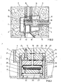
- the spinning beam 1 shows the top view of the spinning beam 1 shown in cross section in FIG. 2, which has a plurality of nozzle arrangements arranged in series one behind the other for melt spinning synthetic threads made of thermoplastic polymers.
- the spinning beam 1 essentially consists of a double-walled heating jacket 2, which, in particular, acts as a pressure container for receiving the heat transfer medium vaporous diphenyls, is formed and receives the melt-carrying components in a chamber 6 delimited by plane-parallel machined heat transfer surfaces 3, 4, 5.
- the heating jacket 2 is enclosed in its entirety to reduce heat losses by a sheet metal housing 7, which is stuffed with mineral wool 8 or another suitable insulating material.
- the insulating materials are present as insulating bodies pressed into geometrically simple shapes, which can be removed from the sheet metal housing at the appropriate point by means of closable cutouts.
- a heated melt feed line 9 which is connected to a melting device, such as an extruder or discharge pump, leads through the sheet metal housing 7 from above.
- the melt feed line 9 leads through the double-walled heating jacket 2 and is connected to a cuboid-shaped distributor block, from which branch ducts lead in a vertical direction to the pump blocks 10 lying next to one another.
- a branch leads from this channel to the suction side of the melt metering pump 11 attached to the pump block 10 and at least one pressure channel to an outlet opening 12 (FIG. 3), to which a nozzle pot 13 with a nozzle packet 22 is connected in a pressure-tight manner.
- the heating jacket 2 of the spinning beam 1 is double-walled over its entire length and U-shaped in cross-section, the two U-legs 14 and 15 of the heating jacket 2 being aligned horizontally or vertically (FIG. 7).
- a chamber 6 or one extends over the entire length of the heating jacket 2 extending shaft formed, which is limited at its ends to avoid heat loss by heat-conducting blocks in the form of fillers 16.
- the melt-carrying components such as pump blocks 10, melt metering pumps 11 and the melt distributor block, are accommodated in the chamber 6.
- the melt-carrying components rest on the heat transfer surface 5 of the U-leg 15 facing the chamber 6 and are pressed on by additional tension or compression screws in order to improve the heat transfer to the components to be heated.
- a plurality of nozzle shafts 17, ie, according to FIG. 1, for example, two nozzle shafts 17 per pump block 10, for the installation of the nozzle pots 13 in the heating jacket 2 are welded pressure-tight, starting from the chamber 6 vertically downwards, whereby the lower U-leg 15 of the double-walled heating jacket 2 is penetrated.
- the adjacent nozzle shafts 17 can preferably form a common component which extends over the entire length of the spinning beam 1 and is welded into the heating jacket 2.
- a spinning shaft extension 18 is connected to the vertical nozzle shafts 17 in order to make the nozzle pots 13 more accessible for assembly work.
- the blowing chutes leading downward, but not shown, are flanged to the ⁇ spinning chute extension 18.
- the spinning shaft extension 18 also serves to support and to fasten the spinning beam 1 to a carrier of a work platform or the like.
- the pump block 10 has a preferably circular cylindrical recess 23 on its underside in the region of each nozzle shaft 17.
- a connecting plug 20 with a central melt channel 19 is inserted in this recess 23 in a pressure-tight manner by means of fastening screws 25 distributed around the circumference.
- the melt channel 19 is aligned with the outlet opening 12 of the pump outlet channel in the pump block 10.
- the downward-facing end face 24 of the connecting plug 20 behind the bearing surface of the pump block 10 on the heat transfer surface-5 of the lower U-leg of the heating jacket 2 somewhat jumps back.
- the pump block 10 can be removed and installed from the chamber 6 and no assembly work on the connecting plug 20 can be carried out from the nozzle shaft 17.
- the connecting plug 20 has a thread 21 on its circumference, which can be of multiple threads, or a bayonet lock for simple and quick removal of the nozzle pots 13.
- the nozzle pack 22 accommodated in the nozzle pot 13 consists, in a known manner, of a nozzle plate 26, into which a plurality of nozzle bores are made, one Melt distributor plate 27, in which a filter 28 is arranged in a circular cylindrical recess and from a seal 29 which seals the nozzle packet 22 against the connecting plug 20 by the force of a differential piston 33 under melt pressure.
- the nozzle pack 22 is sealed between the differential piston 33 and the melt distributor plate 27 by a metal membrane 34 which is supported on the melt distributor plate 27.
- the attachment of the nozzle pot 13 to the connecting plug 20 means that the heating jacket 2 no longer has to absorb tensile forces resulting from the melt pressure. This is of great advantage for the dimensioning of the wall thickness of this critical component (pressure vessel).
- Fig. 4 shows the cross section of a spinning beam 1, in which, however, the radially outward-facing outer wall of the heating jacket 2 is essentially circularly curved and consists, for example, of tubular sections cut open in the longitudinal direction in a suitable manner. It has a length that extends to the ends of the horizontal chamber 6 for accommodating the melt-carrying components and the ends of the nozzle shafts 17 which are guided downward through the heating chamber 2.
- the solution shown is simple in terms of production technology and advantageous in terms of the stress caused by the pressure of the heat transfer medium.
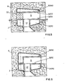
- FIG. 5 and 6 show a schematic representation of cross sections of spinning beams corresponding to FIG. 2, but in which the heating jacket 2 is composed of two mechanically independent heating chambers 30 and 31, which have two separating surfaces 32 in FIG. 5 and one in FIG. 6 .
- the lower U-leg 15 of the heating jacket 2 has a flat separating surface 32, on which all melt-carrying components are placed and fastened when the spinning beam 1 is assembled.
- the heating jacket 2 is then only supplemented by the U-leg 14, which is placed and braced from above and which has an L-shaped cross section according to FIG. 6.
- a corresponding U-shaped cross section is achieved by a heat-conducting block 37 which extends over the length of the heating jacket 2 and which is clamped to the heating chambers 30 and 31 having planar parting surfaces 32 while simultaneously clamping the melt-carrying components.
- All of the exemplary embodiments shown in FIGS. 1 to 6 have the horizontally arranged chamber 6 between the outer U-legs 14, 15 of the heating jacket 2 for the lateral installation of the pump blocks 10 and the melt metering pumps 1] as well as the nozzle shafts installed in the lower U-legs 15 17 as a common constructive feature.
- heating chambers 30, 31 of both U-legs 14, 15 are connected to one another and structural details regarding the heating of the heating jacket 2, which are not essential for understanding the invention, have been omitted in the drawing for the sake of simplicity .
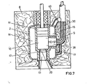
- FIG. 7 finally shows the cross section of a spinning beam 1 according to the design principle on which this invention is based, but in which the U-legs 14, 15 of the heating jacket 2 are oriented vertically and the nozzle shafts 17 starting from the pump shaft 6 vertically downward into the double-walled heating jacket 2 are pressure-tight installed, especially welded.
- the pump block 10 and the melt metering pump 11 are installed in the pump shaft 6 from above. Nevertheless, the nozzle shafts 17 are sealed off at their upper end by the pump block 10, which extends essentially over the entire length of the spinning beam 1, so that air circulation due to a chimney effect is prevented.
- the pump block 10 also has a corresponding number of connecting plugs 20 on the melt outlet side, which can form a common component with the pump block 10 or are non-positively and pressure-tightly connected to the latter.
- the nozzle pots 13 are screwed onto the connecting plugs 20, so that the melt forces are absorbed exclusively by the pump block 10 and the nozzle pots 13 and do not stress the heating jacket 2 and the nozzle shaft 17.
- the polymer melt is supplied here through the melt feed 9 arranged laterally, which opens into a valve module 38 or the like, which is connected to the pump block 10 and is guided through the vertical U-leg 15 of the double-walled heating jacket 2.
- the annular space 39 around the melt feed line is connected to the heating chambers of the heating jacket by branch lines 40, 41.
- the line 41 can, for example, discharge the condensate accumulating in front of the valve module 38.
- the invention also offers the particular advantage that the nozzle package, i.e. in particular, the nozzle plate, distribution elements and filters can be inserted into the nozzle pot before being attached to the heating box. To maintain a spinning station, it is then only necessary to remove the nozzle pot which is in operation and to insert a fresh nozzle pot. Compared to the previously known spinning heads, this saves in particular the laborious overhead work of individually removing and reinstalling the individual parts of the spinning head. It is avoided that the forces exerted by the melt pressure have to be absorbed by the spinning beam or heating jacket to such an extent that the stability suffers as a result.
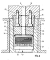
- Fig. 8 explains the attachment of the nozzle cup.
- the spinning beam carries the pump block 10, which is accommodated in a heating box 2, or a melt line module with the melt line 19, via which the spinning station is supplied.
- the pump block 10 (or fusible link module) has a suitable recess into which the connecting plug 20 is inserted.
- An annular seal is inserted between it (20) and the pump block 10, the bearing surface of which essentially determines the level of the forces to be exerted by the fastening screws in order to achieve a tight and pressure-resistant connection.
- the inner diameter of the ring seal also corresponds to that of the melt line 19.
- a thread 21 is incorporated in the connecting plug 20, which can be designed as a multi-start, self-locking and thus quickly tightened thread or as a bayonet connection.
- the nozzle pot 13 receiving the nozzle packet 22 is correspondingly on its upper part has a matching counterpart on the inside.
- the inner diameter of the nozzle pot is substantially equal to the outer diameter of the connecting plug.
- nozzle pot 13 sits the nozzle pack, which consists of the spinneret 26, the pressure or distributor plate 27 with the melt bores, the melt chamber lying between the two and the filter pack 28 inserted into the pot-shaped upper part of the pressure plate 27.
- a piston 33 which closes off the nozzle packet, sits above the pot with the filter pack 28 and is sealed off from the pot by the plate-shaped membrane 34.
- a further ring seal 29 is provided between the piston 33 and the connecting plug 20, to which the above-mentioned seal also applies.
- the thread 21 should be a bayonet lock designed as a three-start thread, which has axially extending recesses extending to the bottom of the thread in respective partial areas of its circumference, which are the same as the thread regions, namely three such recesses should be present evenly distributed. It is understood that the plug 20 and pot 13 fit together.
- the nozzle cup 13 with the nozzle pack and the plate membrane 34 and the piston 33 is then inserted into the bayonet thread of the connecting plug 20 and then only slightly tightened by turning it by about 60 °.
- the high contact pressure required for sealing is generated by the melt pressure itself, which is applied via the plate membrane 34 acts on the piston 33 and compresses the seal 29.
- the piston 33 is sealed by a plate membrane 34 with respect to the interior of the nozzle cup, in which it can be axially displaced.
- the object of the invention is then achieved that the nozzle change process is drastically simplified and accelerated and also that the force resulting from the high melt pressure and introduced into the suspension of the nozzle construction is significantly reduced compared to the effective in the nozzle pack.
- This can improve the heating box.
- the heating box is used to hold a liquid and / or vaporous, pressurized heating medium and to transfer heat to melt-carrying parts, in particular the pump block. It is a critical component in terms of its strength and ductility. According to the invention, it is largely freed from its function of absorbing the force of the melt pressure, and although it can be designed to be weaker, it can nevertheless be improved in its stiffness, which is particularly important for heat transfer to all melt-carrying parts and in particular the pump block.
Landscapes
- Engineering & Computer Science (AREA)
- Mechanical Engineering (AREA)
- Textile Engineering (AREA)
- Spinning Methods And Devices For Manufacturing Artificial Fibers (AREA)
Applications Claiming Priority (8)
| Application Number | Priority Date | Filing Date | Title |
|---|---|---|---|
| DE3419772 | 1984-05-26 | ||
| DE3419772 | 1984-05-26 | ||
| DE3423087 | 1984-06-22 | ||
| DE3423087 | 1984-06-22 | ||
| DE3426211 | 1984-07-17 | ||
| DE3426211 | 1984-07-17 | ||
| DE3428786 | 1984-08-04 | ||
| DE3428786 | 1984-08-04 |
Publications (3)
| Publication Number | Publication Date |
|---|---|
| EP0163248A2 true EP0163248A2 (fr) | 1985-12-04 |
| EP0163248A3 EP0163248A3 (en) | 1987-09-16 |
| EP0163248B1 EP0163248B1 (fr) | 1990-01-10 |
Family
ID=27433129
Family Applications (1)
| Application Number | Title | Priority Date | Filing Date |
|---|---|---|---|
| EP85106256A Expired - Lifetime EP0163248B1 (fr) | 1984-05-26 | 1985-05-22 | Bloc de filage pour le filage au fondu de fibres synthétiques |
Country Status (2)
| Country | Link |
|---|---|
| EP (1) | EP0163248B1 (fr) |
| DE (1) | DE3575313D1 (fr) |
Cited By (17)
| Publication number | Priority date | Publication date | Assignee | Title |
|---|---|---|---|---|
| EP0387470A1 (fr) * | 1989-03-17 | 1990-09-19 | Karl Fischer Industrieanlagen Gmbh | Dispositif pour le filage de matières thermoplastiques fondues |
| EP0545375A2 (fr) * | 1991-12-06 | 1993-06-09 | Akzo Nobel N.V. | Ensemble de filage auto-obturant |
| EP0623693A2 (fr) * | 1993-05-04 | 1994-11-09 | COGNETEX S.p.A. | Bloc de filage amélioré |
| WO1995000684A1 (fr) * | 1993-06-21 | 1995-01-05 | Rieter Automatik Gmbh | Support de plaque de filiere et collecteur-repartiteur pour la filature a chaud de filaments |
| WO1995007378A1 (fr) * | 1993-09-08 | 1995-03-16 | Rieter Automatik Gmbh | Collecteur-repartiteur |
| US5601856A (en) * | 1993-09-08 | 1997-02-11 | Rieter Automatik Gmbh | Spinning beam |
| US5922362A (en) * | 1994-12-02 | 1999-07-13 | Barmag Ag | Spin beam for spinning a plurality of synthetic filament yarns and spinning machine comprising such a spin beam |
| US6083432A (en) * | 1996-09-04 | 2000-07-04 | Barmag Ag | Melt spinning apparatus |
| WO2005123994A1 (fr) * | 2004-06-15 | 2005-12-29 | Zimmer Ag | Dispositif pour filer des fils |
| US7172399B2 (en) | 2002-12-13 | 2007-02-06 | Saurer Gmbh & Co. Kg | Spin beam |
| DE102008013916A1 (de) | 2007-03-26 | 2008-10-02 | Oerlikon Textile Gmbh & Co. Kg | Spinnvorrichtung |
| DE102008035964A1 (de) | 2008-07-31 | 2010-02-04 | Oerlikon Textile Gmbh & Co. Kg | Spinnvorrichtung und Spinndüsenpaket für eine derartige Spinnvorrichtung |
| DE102010005219A1 (de) | 2009-02-11 | 2010-08-12 | Oerlikon Textile Gmbh & Co. Kg | Vorrichtung zum Schmelzspinnen synthetischer Filamente |
| WO2015003823A1 (fr) * | 2013-07-08 | 2015-01-15 | TRüTZSCHLER GMBH & CO. KG | Dispositif de filage de fils |
| CN106811808A (zh) * | 2017-03-24 | 2017-06-09 | 江苏恒科新材料有限公司 | 一种生产细旦丝的双排环吹纺丝箱体设备及其制作方法 |
| CN107803091A (zh) * | 2017-12-06 | 2018-03-16 | 宁波大发化纤有限公司 | 一种化纤纺丝环吹风废气循环浓缩系统 |
| CN113039311A (zh) * | 2018-11-19 | 2021-06-25 | 欧瑞康纺织有限及两合公司 | 纺丝箱 |
Families Citing this family (2)
| Publication number | Priority date | Publication date | Assignee | Title |
|---|---|---|---|---|
| IT1276034B1 (it) * | 1994-11-10 | 1997-10-24 | Barmag Barmer Maschf | Traversa di filatura per la filatura di una pluralita' di fili sintetici e procedimento per la sua produzione |
| DE10160204B4 (de) * | 2001-12-07 | 2006-01-26 | Zimmer Ag | Düsenblock mit einer Stützplatte |
Citations (6)
| Publication number | Priority date | Publication date | Assignee | Title |
|---|---|---|---|---|
| LU60314A1 (fr) * | 1969-02-19 | 1970-04-06 | ||
| CH533693A (de) * | 1971-04-16 | 1973-02-15 | Du Pont Canada | Schmelzspinnvorrichtung für synthetische Filamente |
| DE1966565A1 (de) * | 1969-02-19 | 1973-04-19 | Barmag Barmer Maschf | Beheizbarer spinnbalken zum erzeugen von endlosfaeden aus synthetischem polymeren |
| DE2639282A1 (de) * | 1976-09-01 | 1978-03-02 | Neumuenster Masch App | Beheizbarer verteilerblock zur schmelzverteilung im spinnbalken |
| DE8407945U1 (de) * | 1984-03-15 | 1984-07-05 | Neumünstersche Maschinen- und Apparatebau GmbH (Neumag), 2350 Neumünster | Spinnbalken |
| EP0155835A2 (fr) * | 1984-03-19 | 1985-09-25 | Toray Industries, Inc. | Dispositif pour le filage au fondu |
-
1985
- 1985-05-22 EP EP85106256A patent/EP0163248B1/fr not_active Expired - Lifetime
- 1985-05-22 DE DE8585106256T patent/DE3575313D1/de not_active Expired - Fee Related
Patent Citations (6)
| Publication number | Priority date | Publication date | Assignee | Title |
|---|---|---|---|---|
| LU60314A1 (fr) * | 1969-02-19 | 1970-04-06 | ||
| DE1966565A1 (de) * | 1969-02-19 | 1973-04-19 | Barmag Barmer Maschf | Beheizbarer spinnbalken zum erzeugen von endlosfaeden aus synthetischem polymeren |
| CH533693A (de) * | 1971-04-16 | 1973-02-15 | Du Pont Canada | Schmelzspinnvorrichtung für synthetische Filamente |
| DE2639282A1 (de) * | 1976-09-01 | 1978-03-02 | Neumuenster Masch App | Beheizbarer verteilerblock zur schmelzverteilung im spinnbalken |
| DE8407945U1 (de) * | 1984-03-15 | 1984-07-05 | Neumünstersche Maschinen- und Apparatebau GmbH (Neumag), 2350 Neumünster | Spinnbalken |
| EP0155835A2 (fr) * | 1984-03-19 | 1985-09-25 | Toray Industries, Inc. | Dispositif pour le filage au fondu |
Cited By (28)
| Publication number | Priority date | Publication date | Assignee | Title |
|---|---|---|---|---|
| EP0387470A1 (fr) * | 1989-03-17 | 1990-09-19 | Karl Fischer Industrieanlagen Gmbh | Dispositif pour le filage de matières thermoplastiques fondues |
| US5387097A (en) * | 1991-12-06 | 1995-02-07 | Akzo Nv | Self-sealing spin pack |
| EP0545375A2 (fr) * | 1991-12-06 | 1993-06-09 | Akzo Nobel N.V. | Ensemble de filage auto-obturant |
| EP0545375A3 (en) * | 1991-12-06 | 1993-12-08 | Akzo Nv | Self-sealing spinneret pack |
| EP0623693A2 (fr) * | 1993-05-04 | 1994-11-09 | COGNETEX S.p.A. | Bloc de filage amélioré |
| EP0623693A3 (fr) * | 1993-05-04 | 1995-01-11 | Cognetex Spa | Bloc de filage amélioré. |
| WO1995000684A1 (fr) * | 1993-06-21 | 1995-01-05 | Rieter Automatik Gmbh | Support de plaque de filiere et collecteur-repartiteur pour la filature a chaud de filaments |
| EP0931863A2 (fr) * | 1993-06-21 | 1999-07-28 | Rieter Automatik GmbH | Ensemble de filage pour le filage de filaments continus |
| EP0931863A3 (fr) * | 1993-06-21 | 1999-10-06 | Rieter Automatik GmbH | Ensemble de filage pour le filage de filaments continus |
| WO1995007378A1 (fr) * | 1993-09-08 | 1995-03-16 | Rieter Automatik Gmbh | Collecteur-repartiteur |
| US5601856A (en) * | 1993-09-08 | 1997-02-11 | Rieter Automatik Gmbh | Spinning beam |
| CN1052515C (zh) * | 1993-09-08 | 2000-05-17 | 里特自动有限公司 | 纺丝箱体 |
| US5922362A (en) * | 1994-12-02 | 1999-07-13 | Barmag Ag | Spin beam for spinning a plurality of synthetic filament yarns and spinning machine comprising such a spin beam |
| US6083432A (en) * | 1996-09-04 | 2000-07-04 | Barmag Ag | Melt spinning apparatus |
| US7172399B2 (en) | 2002-12-13 | 2007-02-06 | Saurer Gmbh & Co. Kg | Spin beam |
| WO2005123994A1 (fr) * | 2004-06-15 | 2005-12-29 | Zimmer Ag | Dispositif pour filer des fils |
| DE102008013916A1 (de) | 2007-03-26 | 2008-10-02 | Oerlikon Textile Gmbh & Co. Kg | Spinnvorrichtung |
| DE102008035964A1 (de) | 2008-07-31 | 2010-02-04 | Oerlikon Textile Gmbh & Co. Kg | Spinnvorrichtung und Spinndüsenpaket für eine derartige Spinnvorrichtung |
| DE102010005219A1 (de) | 2009-02-11 | 2010-08-12 | Oerlikon Textile Gmbh & Co. Kg | Vorrichtung zum Schmelzspinnen synthetischer Filamente |
| WO2015003823A1 (fr) * | 2013-07-08 | 2015-01-15 | TRüTZSCHLER GMBH & CO. KG | Dispositif de filage de fils |
| CN105378161A (zh) * | 2013-07-08 | 2016-03-02 | 特吕茨施勒有限及两合公司 | 用于纺线的装置 |
| CN105378161B (zh) * | 2013-07-08 | 2017-09-26 | 欧瑞康纺织有限及两合公司 | 用于纺线的装置以及对其进行加热的方法 |
| CN106811808A (zh) * | 2017-03-24 | 2017-06-09 | 江苏恒科新材料有限公司 | 一种生产细旦丝的双排环吹纺丝箱体设备及其制作方法 |
| CN106811808B (zh) * | 2017-03-24 | 2023-02-24 | 江苏恒科新材料有限公司 | 一种生产细旦丝的双排环吹纺丝箱体设备及其制作方法 |
| CN107803091A (zh) * | 2017-12-06 | 2018-03-16 | 宁波大发化纤有限公司 | 一种化纤纺丝环吹风废气循环浓缩系统 |
| CN107803091B (zh) * | 2017-12-06 | 2023-04-18 | 宁波大发新材料有限公司 | 一种化纤纺丝环吹风废气循环浓缩系统 |
| CN113039311A (zh) * | 2018-11-19 | 2021-06-25 | 欧瑞康纺织有限及两合公司 | 纺丝箱 |
| CN113039311B (zh) * | 2018-11-19 | 2023-08-22 | 欧瑞康纺织有限及两合公司 | 纺丝箱 |
Also Published As
| Publication number | Publication date |
|---|---|
| EP0163248A3 (en) | 1987-09-16 |
| DE3575313D1 (de) | 1990-02-15 |
| EP0163248B1 (fr) | 1990-01-10 |
Similar Documents
| Publication | Publication Date | Title |
|---|---|---|
| EP0163248B1 (fr) | Bloc de filage pour le filage au fondu de fibres synthétiques | |
| EP0122464B1 (fr) | Tête de filage pour le filage au fondu de filaments | |
| DE4447211C2 (de) | Vorrichtung zur Trennung von Stoffgemischen mittels voneinander beabstandeter, gestapelter Membranelemente | |
| DE19540907C5 (de) | Spinnbalken zum Spinnen einer Mehrzahl von synthetischen Fäden und dessen Herstellung | |
| EP0436105B1 (fr) | Dispositif de filage | |
| WO1996017116A1 (fr) | Collecteur-repartiteur permettant de filer une pluralite de fils synthetiques et installations de filage pourvues de ce type de collecteur-repartiteur | |
| EP0208139A1 (fr) | Disposition d'étanchéité pour des arbres, spécialement pour un dispositif de traitement continu de milieux très visqueux | |
| DE4224652C2 (de) | Spinnvorrichtung zum Schmelzspinnen insbesondere thermosplastischer Mehrkomponentenfäden | |
| DE3113495C2 (de) | Spinnbalken für Schmelzspinnanlagen für synthetische Hochpolymere | |
| EP0946796B1 (fr) | Collecteur-repartiteur | |
| EP0828017B1 (fr) | Bloc de filage | |
| DE2945317C2 (de) | Vorrichtung zur Wasserentsalzung und -reinigung durch Umgekehrte Osmose und Ultrafiltration | |
| EP0271801B1 (fr) | Ensemble de filage | |
| EP2122019B1 (fr) | Dispositif de filage à chaud de filaments synthétiques | |
| WO1992000129A1 (fr) | Element de colonne destine a recevoir des echangeurs de chaleur a plaques | |
| DE10235151B4 (de) | Haltevorrichtung für eine Extrusionsdüse | |
| DE2447369A1 (de) | Verfahren und vorrichtung zum einmischen von niedrigviskosen fluessigkeiten in hochviskose medien | |
| DE3324833C2 (de) | Haltevorrichtung für rechteckige Düsenplatten | |
| DE8418785U1 (de) | Spinnbalken zum Schmelzspinnen synthetischer Fäden | |
| DE2448100A1 (de) | Verfahren zur kontinuierlichen polymerisation von lactamen | |
| DE2460642C3 (de) | Vorrichtung zum Schmelzspinnen eines faserbildenden synthetischen Polymers | |
| DE4114064A1 (de) | Spinnkopf | |
| WO2016110300A1 (fr) | Rampe de filage pour la production de filaments filés à chaud | |
| EP4309804A1 (fr) | Dispositif de transport pour transporter une masse pâteuse et plaque de suivi pour un tel dispositif | |
| DE102010005219A1 (de) | Vorrichtung zum Schmelzspinnen synthetischer Filamente |
Legal Events
| Date | Code | Title | Description |
|---|---|---|---|
| PUAI | Public reference made under article 153(3) epc to a published international application that has entered the european phase |
Free format text: ORIGINAL CODE: 0009012 |
|
| AK | Designated contracting states |
Designated state(s): CH DE FR GB IT LI |
|
| RAP1 | Party data changed (applicant data changed or rights of an application transferred) |
Owner name: B A R M A G AG |
|
| PUAL | Search report despatched |
Free format text: ORIGINAL CODE: 0009013 |
|
| AK | Designated contracting states |
Kind code of ref document: A3 Designated state(s): CH DE FR GB IT LI |
|
| 17P | Request for examination filed |
Effective date: 19870904 |
|
| 17Q | First examination report despatched |
Effective date: 19880816 |
|
| ITF | It: translation for a ep patent filed |
Owner name: DE DOMINICIS & MAYER S.R.L. |
|
| GRAA | (expected) grant |
Free format text: ORIGINAL CODE: 0009210 |
|
| AK | Designated contracting states |
Kind code of ref document: B1 Designated state(s): CH DE FR GB IT LI |
|
| ET | Fr: translation filed | ||
| REF | Corresponds to: |
Ref document number: 3575313 Country of ref document: DE Date of ref document: 19900215 |
|
| GBT | Gb: translation of ep patent filed (gb section 77(6)(a)/1977) | ||
| PLBE | No opposition filed within time limit |
Free format text: ORIGINAL CODE: 0009261 |
|
| STAA | Information on the status of an ep patent application or granted ep patent |
Free format text: STATUS: NO OPPOSITION FILED WITHIN TIME LIMIT |
|
| 26N | No opposition filed | ||
| ITTA | It: last paid annual fee | ||
| PGFP | Annual fee paid to national office [announced via postgrant information from national office to epo] |
Ref country code: GB Payment date: 19950511 Year of fee payment: 11 |
|
| PGFP | Annual fee paid to national office [announced via postgrant information from national office to epo] |
Ref country code: FR Payment date: 19950519 Year of fee payment: 11 |
|
| PGFP | Annual fee paid to national office [announced via postgrant information from national office to epo] |
Ref country code: CH Payment date: 19950526 Year of fee payment: 11 |
|
| PG25 | Lapsed in a contracting state [announced via postgrant information from national office to epo] |
Ref country code: GB Effective date: 19960522 |
|
| PG25 | Lapsed in a contracting state [announced via postgrant information from national office to epo] |
Ref country code: LI Effective date: 19960531 Ref country code: CH Effective date: 19960531 |
|
| GBPC | Gb: european patent ceased through non-payment of renewal fee |
Effective date: 19960522 |
|
| REG | Reference to a national code |
Ref country code: CH Ref legal event code: PL |
|
| PG25 | Lapsed in a contracting state [announced via postgrant information from national office to epo] |
Ref country code: FR Effective date: 19970131 |
|
| REG | Reference to a national code |
Ref country code: FR Ref legal event code: ST |
|
| PGFP | Annual fee paid to national office [announced via postgrant information from national office to epo] |
Ref country code: DE Payment date: 20010726 Year of fee payment: 17 |
|
| PG25 | Lapsed in a contracting state [announced via postgrant information from national office to epo] |
Ref country code: DE Free format text: LAPSE BECAUSE OF NON-PAYMENT OF DUE FEES Effective date: 20021203 |