EP0623693A2 - Bloc de filage amélioré - Google Patents
Bloc de filage amélioré Download PDFInfo
- Publication number
- EP0623693A2 EP0623693A2 EP94200782A EP94200782A EP0623693A2 EP 0623693 A2 EP0623693 A2 EP 0623693A2 EP 94200782 A EP94200782 A EP 94200782A EP 94200782 A EP94200782 A EP 94200782A EP 0623693 A2 EP0623693 A2 EP 0623693A2
- Authority
- EP
- European Patent Office
- Prior art keywords
- boiler body
- spinning
- spinning block
- support
- groove
- Prior art date
- Legal status (The legal status is an assumption and is not a legal conclusion. Google has not performed a legal analysis and makes no representation as to the accuracy of the status listed.)
- Withdrawn
Links
Images


Classifications
-
- D—TEXTILES; PAPER
- D01—NATURAL OR MAN-MADE THREADS OR FIBRES; SPINNING
- D01D—MECHANICAL METHODS OR APPARATUS IN THE MANUFACTURE OF ARTIFICIAL FILAMENTS, THREADS, FIBRES, BRISTLES OR RIBBONS
- D01D4/00—Spinnerette packs; Cleaning thereof
- D01D4/08—Supporting spinnerettes or other parts of spinnerette packs
-
- D—TEXTILES; PAPER
- D01—NATURAL OR MAN-MADE THREADS OR FIBRES; SPINNING
- D01D—MECHANICAL METHODS OR APPARATUS IN THE MANUFACTURE OF ARTIFICIAL FILAMENTS, THREADS, FIBRES, BRISTLES OR RIBBONS
- D01D4/00—Spinnerette packs; Cleaning thereof
Definitions
- This invention relates to an improved spinning block for spinning thermoplastic material in which said block comprises a clamping means for removably connecting the spinning block to a boiler body of a spinning machine.
- thermoplastic masses such as polyesters, polyamides etc.
- Said spinning blocks have a heating system using diphenyl vapour or a similar fluid originating from a vapour generator in common with a ducting system for distributing the directly fed vapour.
- the individual spinning blocks are positioned one following the other along the spinning beam of the boiler body.
- the heat from the diphenyl vapour is transferred to the blocks by thermal conductivity or by thermal convection. Arrangements of this kind have been known for some time in the synthetic yarn production field. However, even today such spinning blocks suffer from various technical problems from a number of aspects.
- the spinning block illustrated and described in European patent 0163248 has its threaded upper end arranged to connect to the threaded circumferential side of a flange previously screwed to the boiler body.
- connecting and removing the spinning block to and from the boiler body, or more precisely the spinning beam are operations which arise fairly frequently during normal maintenance and during the changing of yarn production batches.
- the said fixing operation requires a certain ability on the part of the operator as he cannot directly see the two threaded portions to be connected together, with the possibility therefore of imprecise initial screwing with damage to the threads. These threads can also be damaged by impact and by the presence of particles soiling the thread, all this being the result of the fact that the joint is in an upper internal position not visible to the operator connecting the spinning block.
- the spinning block described in the aforesaid European patent and also those spinning blocks used up to the present time in the art have considerable drawbacks because of poor thermal energy transfer conditions resulting from a construction in which the material continuity of the components of the spinning block is interrupted, so that thermal energy transmission to more or less large regions takes place by radiation. It is well known that radiation is a form of thermal energy transmission which depends on a number of variables which are not easy to control, especially in complex production plants.
- the object of the improvement according to the invention is to eliminate damage to the connection thread and enable the spinning block to be heated to a temperature which is rigorously uniform throughout its parts. Reliable and rapid connection and removal can be surprisingly achieved with the improved spinning block described and claimed in the present invention, with the precise intention of attaining an operational life exceeding that previously attainable.
- the present invention provides an improved spinning block for spinning molten thermoplastic materials to obtain yarn, said spinning block comprising a clamping ring operating at the lower end of the circumferential edge of the spinning block to fix this latter to the overlying boiler body by means of a releasable connection.
- the clamping ring has a circular rim of height sufficient to engage a number of threads of one or more starts on a plate or flange fixed to the lower end of the boiler body by screw elements.
- the clamping ring comprises cam-like circumferential projections for its removable connection to the plate, this latter being fixed to the lower end of the boiler body.
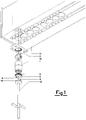
- the polymer in the molten liquid state is fed under pressure through the central duct 5 in the flange 10 which is fixed to the boiler body 11 by the screw elements 15 and 14.
- the spinning block 1, wherein the aforesaid internal elements have bee, preassembled, is positioned within the boiler body 11 to the lower end of which a plate 3 is fixed by connection screws 7.
- Said plate 3 fixed to the boiler body 11, has a threaded central hole and the clamping ring 6 has a corresponding peripheral thread 9 (Fig.1) or the central hole has cam-like circumferential recesses and the clamping ring 6 has corresponding cam-like circumferential projections 9a (see Figure 2).
- the mounting tool 12 with magnetic ends 19 and with positioning and insertion teeth 4, enables the clamping ring 6 to be gripped to screw it to the plate 3, hence fixing the spinning block 1 to the boiler body 11 by a releasable connection.
- Rotation for screwing purposes is achieved by engagement between the teeth 4 and slots 8 in the clamping ring 6.
- This latter enables the operator, who has an unimpeded view, to clamp the block 1 to the overlying boiler body 11 accurately and quickly, avoiding any damage to the thread or cam contour 9 by impact.
- the clamping ring 6 achieves the surprising advantage of material continuity between the boiler body 11 and the spinning block 1 via the plate 3. The said material continuity ensures thermal energy transmission by conduction, to achieve when under steady working conditions a temperature which is rigorously uniform throughout the spinning block 1, to obtain optimum quality of the synthetic yarn produced.
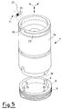
- the spinning block 1 still comprises, as in the embodiment of the preceding figures, a support and fixing element 1a for housing the distributor disc 16 for the molten mass, the filter cylinder 18, the disc 20 comprising sized holes and the disc 2 comprising gauging nozzles, and is removably fixable to the boiler body 11 of the spinning machine within a skirt of the boiler body 11.
- the clamping ring 6 is associated with the lower end of the element 1a to removably connect it rigidly to the overlying boiler body 11.
- the boiler body 11 comprises, preferably in the region in which the upper end of the support and fixing element 1a is housed, at least one support peg 21 projecting towards the interior of the seat 22 housing the element 1a.
- the peg 21 is preferably screwed into the boiler body 11 as shown in Figure 7.
- the element 1a comprises at least one circumferential groove 23 and at least one recess 24 in its outer wall, the recess 24 connecting the groove 23 to the upper edge of the element 1a.
- the groove 23 extends preferably along the entire circumference of the element 1a and has a width in the longitudinal direction of the element 1a which is substantially greater than the diameter of the peg 21.
- the arrangement and configuration of the peg 21, groove 23 and recess 24 are such as to enable the element 1a to move axially within its seat to beyond the peg 21 when the element 1a is in that angular position in which the recess 24 is vertically aligned with the peg 21.
- the element 1a complete with its internal elements 16, 18, 20, 2 is then inserted in this angular position by the operator and is then rotated about its axis into another angular position in which the recess 24 is no longer vertically aligned with the peg 21, so that the peg 21 acts as a support element for the element 1a by engaging the upper wall of the groove 23 as shown in the left part of Figure 6.
- the operator ceases holding the spinning block 1, which then remains retained by the boiler body 11, so substantially facilitating the fixing of the block.
- the mutual arrangement of the peg 21 and groove 23 is such that when the block 1 is in its suspended position the lower part of the thread of the boiler body 11 which is to receive the clamping ring 6 remains free and accessible, as can be seen by observing the left hand block of Figure 6. The operator can hence easily begin to apply the ring 6. On continuing its rotation by the tool 12, the block 1 is progressively shifted by axial movement into its final fixing position, shown on the right hand side of Figure 6.
- the presence of the support peg 21 or the like also facilitates the removal of the block 1, by enabling it to remain temporarily suspended while the removal of the ring 6 is completed.
- the ring 6 is removably fixable by rotation to the lower part of the skirt of the boiler body 11 instead of to the plate 3.
- the clamping ring 6 comprises engagement means for rotational engagement with the support and fixing element 1a during the fixing and removal of the element 1a to and from the boiler body 11.
- these means can advantageously comprise at least one pin 25 radially projecting into the ring 6 and at least one recess 26 provided in the lower edge of the support and fixing element 1a, to receive the pin 25.
- Two diametrically opposite pins 25 and two diametrically opposite recesses 26 are preferably provided.
- the pins 25 penetrate into their respective recesses 26 to also rotate the element 1a both during the mounting and during the removal of the block 1.
- the groove 23 could extend only through a certain circular arc starting from the position of the recess 24.
- the element 1a would remain rotationally at rest during its mounting and removal and said rotation engagement means would not be provided.
- Advantageously two diametrically opposite support pegs or the like 21 could be provided together with two recesses 24 with relative partial circumferential grooves 23 or a single annular groove 23.
- the groove 23 and recess 24 or the grooves 23 and recesses 24 together with the peg or pegs 21 could be provided for example in an intermediate region of the element 1a.
Applications Claiming Priority (2)
| Application Number | Priority Date | Filing Date | Title |
|---|---|---|---|
| ITMI930880 | 1993-05-04 | ||
| ITMI930880A IT1272396B (it) | 1993-05-04 | 1993-05-04 | Blocco di filatura perfezionato |
Publications (2)
| Publication Number | Publication Date |
|---|---|
| EP0623693A2 true EP0623693A2 (fr) | 1994-11-09 |
| EP0623693A3 EP0623693A3 (fr) | 1995-01-11 |
Family
ID=11365989
Family Applications (1)
| Application Number | Title | Priority Date | Filing Date |
|---|---|---|---|
| EP94200782A Withdrawn EP0623693A3 (fr) | 1993-05-04 | 1994-03-25 | Bloc de filage amélioré. |
Country Status (3)
| Country | Link |
|---|---|
| EP (1) | EP0623693A3 (fr) |
| CN (1) | CN1049932C (fr) |
| IT (1) | IT1272396B (fr) |
Cited By (1)
| Publication number | Priority date | Publication date | Assignee | Title |
|---|---|---|---|---|
| WO2001009413A1 (fr) * | 1999-07-30 | 2001-02-08 | Lurgi Zimmer Ag | Filiere compacte auto-etanche pour procede de filage a fusion |
Families Citing this family (2)
| Publication number | Priority date | Publication date | Assignee | Title |
|---|---|---|---|---|
| EP4144776A1 (fr) | 2020-04-29 | 2023-03-08 | China Petroleum & Chemical Corporation | Greffe de polypropylène contenant un groupe anhydride et procédé de préparation de greffe de polypropylène |
| CA3228273A1 (fr) | 2021-08-04 | 2023-02-09 | China Petroleum & Chemical Corporation | Materiau modifie d'isolation de polypropylene flexible, son procede de preparation et son application |
Citations (3)
| Publication number | Priority date | Publication date | Assignee | Title |
|---|---|---|---|---|
| EP0122464A2 (fr) * | 1983-03-23 | 1984-10-24 | B a r m a g AG | Tête de filage pour le filage au fondu de filaments |
| EP0163248A2 (fr) * | 1984-05-26 | 1985-12-04 | B a r m a g AG | Bloc de filage pour le filage au fondu de fibres synthétiques |
| DE3818017A1 (de) * | 1987-06-06 | 1988-12-15 | Barmag Barmer Maschf | Spinnkopf |
-
1993
- 1993-05-04 IT ITMI930880A patent/IT1272396B/it active IP Right Grant
-
1994
- 1994-03-25 EP EP94200782A patent/EP0623693A3/fr not_active Withdrawn
- 1994-04-28 CN CN94105392.XA patent/CN1049932C/zh not_active Expired - Fee Related
Patent Citations (4)
| Publication number | Priority date | Publication date | Assignee | Title |
|---|---|---|---|---|
| EP0122464A2 (fr) * | 1983-03-23 | 1984-10-24 | B a r m a g AG | Tête de filage pour le filage au fondu de filaments |
| EP0300120A2 (fr) * | 1983-03-23 | 1989-01-25 | B a r m a g AG | Filière pour le filage au fondu de filaments |
| EP0163248A2 (fr) * | 1984-05-26 | 1985-12-04 | B a r m a g AG | Bloc de filage pour le filage au fondu de fibres synthétiques |
| DE3818017A1 (de) * | 1987-06-06 | 1988-12-15 | Barmag Barmer Maschf | Spinnkopf |
Cited By (2)
| Publication number | Priority date | Publication date | Assignee | Title |
|---|---|---|---|---|
| WO2001009413A1 (fr) * | 1999-07-30 | 2001-02-08 | Lurgi Zimmer Ag | Filiere compacte auto-etanche pour procede de filage a fusion |
| US6716016B1 (en) * | 1999-07-30 | 2004-04-06 | Zimmer Aktiengesellschaft | Self-sealing compact spinneret for a melt spinning process |
Also Published As
| Publication number | Publication date |
|---|---|
| CN1049932C (zh) | 2000-03-01 |
| ITMI930880A0 (it) | 1993-05-04 |
| ITMI930880A1 (it) | 1994-11-04 |
| EP0623693A3 (fr) | 1995-01-11 |
| CN1108315A (zh) | 1995-09-13 |
| IT1272396B (it) | 1997-06-23 |
Similar Documents
| Publication | Publication Date | Title |
|---|---|---|
| US4050866A (en) | Apparatus for melt-spinning | |
| CA1338691C (fr) | Systeme porte-outil et methode d'utilisation connexe | |
| US8468921B2 (en) | Brush cylinder | |
| US4161386A (en) | Nozzle for injection molding machines | |
| DE60110068T2 (de) | Steckerstiftaufbau für maschine zum polieren der endfläche einer optischen faserverbindung | |
| EP0623693A2 (fr) | Bloc de filage amélioré | |
| DE2752591A1 (de) | Aufloesewalze fuer eine offenend- spinnmaschine | |
| US4696633A (en) | Melt spinning apparatus | |
| KR0122465B1 (ko) | 분사가공장치(Device for blow ― texturing) | |
| EP0155838B1 (fr) | Appareil de pulvérisation | |
| US4681522A (en) | Melt spinning apparatus | |
| US5146643A (en) | End brush with male projection | |
| US4278534A (en) | Method for separation of material mixtures, containing abrasive particles, in a hydrocyclone separator | |
| DE2524093A1 (de) | Zufuehr- und aufloeseeinrichtung fuer ein offenend-spinnaggregat | |
| CA1323966C (fr) | Rouleau de brosses servant au brossage de plaques metalliques | |
| WO2000003075A1 (fr) | Appareil pour le filage a chaud d'un produit alimentaire | |
| JP3128991B2 (ja) | 糸条の捲縮加工装置 | |
| EP1275756B1 (fr) | Dispositif pour le filage au fondu et refroidissement de faisceaux de filaments | |
| US3585706A (en) | Method of manufacturing a combing cylinder for a combing machine | |
| EP1231302A1 (fr) | Dispositif pour le filage au fondu et refroidissement de faisceaux de filaments | |
| GB2322385A (en) | Thread guiding wheel for textile machines | |
| US3553773A (en) | Spinneret assembly | |
| GB1587377A (en) | Winding units of textile machines | |
| JPH0226943Y2 (fr) | ||
| EP0353429A1 (fr) | Métier à filer à bout libre |
Legal Events
| Date | Code | Title | Description |
|---|---|---|---|
| PUAI | Public reference made under article 153(3) epc to a published international application that has entered the european phase |
Free format text: ORIGINAL CODE: 0009012 |
|
| AK | Designated contracting states |
Kind code of ref document: A2 Designated state(s): AT BE CH DE DK ES FR GB GR IE IT LI LU MC NL PT SE |
|
| PUAL | Search report despatched |
Free format text: ORIGINAL CODE: 0009013 |
|
| AK | Designated contracting states |
Kind code of ref document: A3 Designated state(s): AT BE CH DE DK ES FR GB GR IE IT LI LU MC NL PT SE |
|
| 17P | Request for examination filed |
Effective date: 19950608 |
|
| 17Q | First examination report despatched |
Effective date: 19961115 |
|
| GRAG | Despatch of communication of intention to grant |
Free format text: ORIGINAL CODE: EPIDOS AGRA |
|
| GRAG | Despatch of communication of intention to grant |
Free format text: ORIGINAL CODE: EPIDOS AGRA |
|
| GRAH | Despatch of communication of intention to grant a patent |
Free format text: ORIGINAL CODE: EPIDOS IGRA |
|
| STAA | Information on the status of an ep patent application or granted ep patent |
Free format text: STATUS: THE APPLICATION IS DEEMED TO BE WITHDRAWN |
|
| 18D | Application deemed to be withdrawn |
Effective date: 19980523 |