EP0931863A2 - Ensemble de filage pour le filage de filaments continus - Google Patents
Ensemble de filage pour le filage de filaments continus Download PDFInfo
- Publication number
- EP0931863A2 EP0931863A2 EP98122845A EP98122845A EP0931863A2 EP 0931863 A2 EP0931863 A2 EP 0931863A2 EP 98122845 A EP98122845 A EP 98122845A EP 98122845 A EP98122845 A EP 98122845A EP 0931863 A2 EP0931863 A2 EP 0931863A2
- Authority
- EP
- European Patent Office
- Prior art keywords
- nozzle
- package
- melt
- heat
- seal
- Prior art date
- Legal status (The legal status is an assumption and is not a legal conclusion. Google has not performed a legal analysis and makes no representation as to the accuracy of the status listed.)
- Granted
Links
Images

Classifications
-
- D—TEXTILES; PAPER
- D01—NATURAL OR MAN-MADE THREADS OR FIBRES; SPINNING
- D01D—MECHANICAL METHODS OR APPARATUS IN THE MANUFACTURE OF ARTIFICIAL FILAMENTS, THREADS, FIBRES, BRISTLES OR RIBBONS
- D01D4/00—Spinnerette packs; Cleaning thereof
- D01D4/08—Supporting spinnerettes or other parts of spinnerette packs
-
- D—TEXTILES; PAPER
- D01—NATURAL OR MAN-MADE THREADS OR FIBRES; SPINNING
- D01D—MECHANICAL METHODS OR APPARATUS IN THE MANUFACTURE OF ARTIFICIAL FILAMENTS, THREADS, FIBRES, BRISTLES OR RIBBONS
- D01D4/00—Spinnerette packs; Cleaning thereof
Definitions
- the invention relates to a nozzle package for spinning continuous filaments according to Preamble of the first claim.
- the temperature control of the is of fundamental importance in melt spinning Melt from the extruder until it emerges from the spinneret. It is mostly towards it make sure that the melt has the same thermal history for all threads, both in temperature and in residence time. Slight deviations from for example, only 2 ° C can already differ from visible staining or lead to increased capillary breakage rates.
- To ensure a constant temperature are currently the product lines and the spinning beam as a rule condensation heated.
- the condensation heating enables a very exact Temperature control, because with this principle above all the places with saturated steam charged room are heated intensely, the lower temperature have than the condensation temperature of the saturated steam. The result is one very even temperature distribution on the condensation surfaces. This The heating principle thus enables a precise degree of accuracy with relatively simple means Temperature control of the entire melt distribution system.
- a "good heat transfer" due to the surface pressure of the nozzle plate holder and a carrier should also be achieved according to DE-C-1529819. But this requires a special training of the carrier, which is an effective heating of this part impaired.
- a known spinning beam can be found, for example, in DE-Gbm 84 07 945 remove.
- the holder for the nozzle pot (the Nozzle package) welded into the heating box and thus practically part of the Heating box.
- the arrangement of the nozzle pot in the receptacle is provided that a stratification consisting of nozzle plate, filter housing and nozzle bowl bottom is screwed to the bottom of the receptacle, by means of the layering penetrating bolt, which is screwed into a buffer thread in the base of the receptacle are.
- the nozzle pot has one Hollow cylinder on which carries the nozzle plate with an inwardly projecting heel which the filter housing is supported by a ring seal.
- a piston axially movable in the hollow cylinder with a central through hole, which when the nozzle pot is unfilled, over a membrane like an inverted Supports plates outside the box.
- the piston stroke is caused by a space surrounding the central recess Sealing ring limited, which is supported against a threaded ring, by means of bolts is attached to a rigid pump block arranged in the heating box.
- the hollow cylinder is attached to the threaded ring with an external thread screwed on an internal thread, so that of the hollow cylinder with its shoulder worn nozzle pot is attached to the heating box. To remove the nozzle pot unscrew the hollow cylinder from the threaded ring.
- the thread and the Membranes of this arrangement are subject to a very considerable load because of which extends over the entire cross section of the interior of the hollow cylinder extending sealing membrane this and the thread with a through the pressure and the cross-section specified force are loaded, which because of relatively large cross-section of the interior of the hollow cylinder can be up to 15 t can.
- the consequence of this is an interrupted by the annulus Heat transfer from the relevant wall of the heating box to the hollow cylinder especially in the area in which he carries the nozzle plate with his heel, so that the required constant sufficient heating of the nozzle plate is difficult.
- the invention has for its object the assembly and disassembly of the Nozzle pots to lighten, especially to reduce the load on the seal accelerate.
- the sealing washers are advisable to form with a central through hole bell-shaped, with the through hole when installed the surrounding floor against the bottom of the recordings and the outer edge the sealing washers are supported on an annular shoulder in the nozzle cup. Based on these The design of the sealing washers presses when the nozzle pot is filled under the pressure of the melt on the one hand to the bottom of the recording, with what the sealing effect between the nozzle pot in the area of the central through hole Sealing washer and the base of the recording automatically on each prevailing pressure.
- the nozzle pots are appropriately designed so that in a hollow cylinder
- the nozzle plate, a filter housing and above it the bottom of the nozzle pot are layered with a central recess forming threaded ring
- the hollow cylinder with one paragraph carries the nozzle plate and the threaded ring into a nut thread of the Hollow cylinder is screwed in while compressing the layered components, the annular shoulder against the sealing disk arranged on the filter housing presses the conical inner surface of the threaded ring in such a way that the sealing washer with its their through hole area from the central recess of the threaded ring slightly emerges.
- the sealing washer is centered by the conical Inner surface of the threaded ring, so that after mounting the nozzle pot with correct position of the sealing washer by means of the above-mentioned bayonet catch in the Recording can be attached.
- the sealing disc then immediately presses into its correct one Position against the bottom of the intake, with which the nozzle pot for filling with processing mass is sealed and prepared.
- the cylindrical projection on the filter housing against the nozzle plate with which the formed by the projection ring-like recess within the projection the height of this projection is limited.
- the one inserted in the recess The sealing ring cannot be squeezed together excessively.
- the sealing effect of the sealing ring is determined automatically by that in the nozzle cup prevailing pressure, as this pressure pushes the sealing ring outwards against the projection presses and a possible gap between the projection and the opposite surface of the nozzle plate automatically closes, the projection also offers the advantage that the entire height of the nozzle pot is co-determined, which therefore has a defined dimension in the installed state.
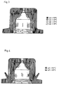
- Fig. 1 shows the heat flows on a nozzle package.
- the melt makes the most of the heat input here as well the heat dissipation. Ideally, the two heat flows are equal in amount. This would mean that the melt remains constant until it emerges from the nozzle Temperature. To ensure this, the remaining heat flows in the Balance.
- the heat losses present particular difficulties here the nozzle plate. Since it cannot be isolated, a large part of the Amount of heat given off to the environment in the form of radiation and convection. This amount of heat must now as far as possible from the spinning beam over the Nozzle pack to the nozzle plate to cool the melt to a minimum.
- the temperature difference to Diphyl temperature is a measure of the amount of heat, that of the melt is withdrawn.
- a temperature difference of 10 ° C for the nozzle plate without polymer to compensate for the melt will depend on in production Polymer, nozzle diameter and throughput, the melt on average around 0.5 ° C cooled down.
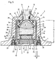
- FIG. 5 shows a section of a spinning beam with a nozzle pack (especially a nozzle plate holder) according to this invention.
- the spinning beam comprises a heating box 1, in the melt lines and not shown Melt pumps protrude into it, such as in the figures above mentioned DE-Gmb 84 07 945 is shown.
- the heating box 1 is the receptacle 2 used, for example by welding, which consists of the wall 3, the inwards through the bottom 4 ago is completed.
- the melt channel 8 which is connected to a not shown Melt pump is connected.
- the nozzle pot 6 is a rotating body, it is in the figure like the receptacle 2 in Section shown.
- the nozzle pot 6 consists of components stacked on top of one another, namely from the nozzle plate 9, the filter housing 10 and the threaded ring 11. This three components are inserted into the hollow cylinder 12, which with its paragraph 13 Nozzle plate 9 carries.
- the hollow cylinder 12 is on the side of the threaded ring 11 the internal thread 14 into which the threaded ring 11 with its External thread 15 is screwed.
- the threaded ring 11 is provided with the blind holes 16 and 17, in which fits a suitable hook wrench.
- Screwing in the threaded ring 11 in the hollow cylinder 12 is through the cylindrical projection 18 on the nozzle plate 9 facing side of the filter housing 10 limited. If when screwing in the Threaded ring 11 of the projection 18 abuts the surface 19 of the nozzle plate 9 the entire length of the nozzle cup 6 is determined. Inside the cylindrical Projection 18 has an annular recess through the sealing ring 20 is filled out.
- the sealing ring 20 is a pressure to be processed Mass, the gap 21 between the surface 19 and the Fills the bottom surface 22 of the filter housing 10, towards the outside against the cylindrical one Projection 18 pressed, which automatically under the effect of this pressure a seal adapted to the pressure between the filter housing 10 and the Nozzle plate 9 results.
- the shoulders 23 are part of the Insert pieces 25, which are inserted into the wall 3 of the receptacle 2 and with the Wall 3 are screwed tight, by means of the bolts 26.
- the shoulders 23 and the supports 24 together form a bayonet lock, which axially the nozzle pot 6 locked.
- the bayonet catch forms over the shoulders 23 and Pads 24 a direct thermal bridge through which the nozzle plate 9 is heated directly.
- the nozzle cup 6 By turning the hollow cylinder 12 and thus the nozzle cup 6 by about 90 ° the connection between the receptacle 2 and the nozzle pot 6 is released. The nozzle pot 6 can then removed through the cylindrical opening 7 from the receptacle 2 and in its parts are disassembled, for example for cleaning the filter housing 10 and the nozzle plate 9.
- the sealing washer 27 comes to the effect, which is essentially conical in shape in the threaded ring 11 is inserted, the conical for receiving the sealing washer 27 Has inner surface 28.
- the sealing washer 27 is supported with its outer edge 29 on the annular shoulder 30, which is part of the filter housing 10 overlying melt distributor 31 is.
- This melt distributor 31 is part of this of the nozzle pot 6, it serves to flow through the melt channel 8 To distribute melt inside the nozzle pot cheaply, whereupon below is received.
- the bottom 32 of the sealing washer 27 stands slightly against the surface 34 of the threaded ring 11, so that when closing of the bayonet catch 24/25 the bottom 32 to the lower surface 35 of the bottom 4 of the Recording 2 is tight. So that is the seal between the before Melt channel 8 penetrates base 4 of receptacle 2 to nozzle bowl 6 manufactured, taking advantage of the inside of the nozzle pot 6th ruling Drukkes, the sealing washer 27 depending on the level of this pressure against the lower surface 35 and the conical inner surface 28 of the threaded ring 11 presses. In addition, the sealing washer 27 is radially outward against the Butt 36 pressed between threaded ring 11 and filter housing 10, so that too a secure seal is achieved here.
- the melt flow is as follows: The melt comes out the melt channel 8 through the through hole 33 to the melt distributor 31, the flows over the melt and reaches the channels 37, of which only two are drawn are. In the illustrated embodiment there are approximately 24 such channels available. The melt then flows through the filter 38 which passes through the grid 39 downwards is completed. The channels 40 are also in the filter housing 10 introduced (about 50 such channels are available), from where the melt in the Gap 21 arrives. Now the melt passes through the nozzle plate 9, and through the bores 41 in capillaries in the lower boundary surface 42 the nozzle plate 9 end. Here the individual filaments emerge, which then close individual threads can be summarized.
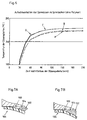
- the dashed curve A represents the warm-up behavior (temperature curve above Time after installation in the spinning beam - without polymer) of a conventional one Nozzle pack in the middle of the nozzle
- the dashed curve B das shows corresponding behavior in the edge part of a conventional package
- the curve C shows the warm-up behavior in the middle of the nozzle of a package according to this invention (e.g. according to Fig. 5)
- curve D which for the most part with curve C coincides
- the warm-up behavior of the peripheral part of the novel package represents.
- the new nozzle package with the improved heat flow reaches it much earlier Final temperature as the conventional package of nozzles. Furthermore, the Final temperature of the new nozzle package about 10 ° C higher, which the Corresponds to calculations. The temperature difference between the center of the nozzle and The edge of the nozzle is already negligible in the conventional design low, but could be improved by the last nuance with the new nozzle package become.
- the experiment thus confirms the calculated results, after which the cooling the melt in the new nozzle package is approx. 0.5 ° C lower than that of the Nozzle pack of conventional design. This value appears to be very low but a crucial one especially in the production of microfilaments Significance for the quality of the yarn produced.
- FIG. 7A shows "optimal" conditions in the area of the melt feed in the "Nozzle throat", that means in the intake in the heating box, which is the nozzle package records.
- the receptacle itself has an axial surface 100, which in the Spinning direction is directed. This surface faces an end face 102 of the nozzle package opposite after the package is in its operating position, with a Gap 104 is present.
- the distance between the end face 102 and Contact surfaces of the support can be used during manufacture or assembly (i.e. during the construction) of the package can be determined without the manufacturing tolerances of the To have to consider heating box.
- a flexible sealing lip 106 extends from the top of the package out to touch surface 100.
- the hardness, flexural strength and dimensions of the flexible lip are selected such that surface-to-surface contact according to FIG. 7A comes about. Ideally, the lip hugs the bumps on the surface 102 on.
- the risk of leakage between the lip and surface 102 is when it first enters the melt through the access channel is small because the melt pressure is low until the Chamber in the package below the lip has been filled. Until this happens, the Lip additionally pressed against surface 102 by the melt, which increases the risk counteracts a leak.
- the contact conditions before the melt enters are as important as the The incorrect construction according to FIG. 7B is intended to represent.
- the spring force of the lip in one Direction upwards too large.
- the lip edge bends again down, leaving a wedge gap between the edge and surface 102 open.
- This results in an attack surface for the incoming melt which "peels" the Lip from surface 102 and can lead to leakage.
- a leak can of course also arise from the fact that the spring force that the lip against the surface 102nd presses, is chosen too low so that the incoming melt in the remaining Gap between the lip and the surface 102 can penetrate.
- the lip is provided on a sealing body that is "embedded" in the package, so that the body is supported by the package against the melt pressure, and only that Lip must deform under the melt pressure.
- a sealing body that is "embedded" in the package, so that the body is supported by the package against the melt pressure, and only that Lip must deform under the melt pressure.
- the lip formed integrally with the body.
- the body can advantageously be formed or be arranged that he additional sealing functions in the package itself can take over.
- the sealing element (the lip) can be plastically deformed under the operating pressure be, the element then after removing the package from the throat before the new product must be replaced.
- the material of the element can be so be chosen so that the element is elastic even under the operating pressure is deformable and therefore reusable, for example if a chrome steel is used.
- the package is reintroduced (before the melt enters) it is Seal preferably elastically deformable.
- the sealing element (the sealing lip and the sealing body) are in operation exposed to the melt.
- a sealing material must therefore be selected that will not react with the melt.
- a metal is preferred, with aluminum and Steel are suitable in most cases.
- a seal according to Fig. 5 (with a lip and a one-piece body part with the conical body part in contact with a conical support surface in the package, e.g. through a Deep-drawing processes or by metal pressing.
- a sheet thickness up to approx. 3 mm e.g. for steel approx. 1 mm and for aluminum 1.5 to 2 mm) can be used.
- the package is preferably provided with a stop, which in the Operating position of the package its angular position about a vertical axis specifies. This allows the arrangement of the holes in the nozzle plate opposite the cooling shaft are predetermined. Where the connection with the carrier by means of of a bayonet catch, at least one element of the The function of the stopper.
- a multi-turn bayonet lock could be used, taking measures at most then have to be taken to the surface pressure over the conditions distribute the closure. This will usually result in tighter manufacturing tolerances require. Since the radial dimension of these requirements is the division (mutual Distance) of the packets in the spinning beam, this dimension should be as possible be kept small because a minimal division is generally desirable.
- the radial distance between the outer surface of the package and the outer end of each The support is preferably not larger than 10 mm. In the case of a multi-course This dimension can be kept smaller than 5 mm. There are preferably no more than three runs per course.
- the invention in its first aspect (connection at the bottom of the package) results in the shortest possible flow paths for the heat between the heating box and the Nozzle plate.
- This aspect of the invention is not for use in combination with a sealing lip, although preferably in combination with a seal is used, which has its full sealing effect due to the melt pressure developed.
- Such seals are also known for example from US 4645444.
- the new type of seal is independent of the connection between the Nozzle pack and the heating box, an advantage - it can, for example Piston seal according to DE-C-12 46 221 or DE-C-15 29 819 or US 4,696,633 replace.
- the cylindrical outer surface of the nozzle package is indicated by M.
- M This The area must have a slightly smaller diameter than the inner surface of the Have jet pharynx to easily insert the package into the throat enable.
- the distance A between the bottom of the pads and the more distant The end face of the package is chosen to be slightly smaller than the depth of the throat Insert the package without touching the end surfaces of the throat guarantee.
- the radial dimension of the edition is indicated with D.
Applications Claiming Priority (3)
| Application Number | Priority Date | Filing Date | Title |
|---|---|---|---|
| CH01853/93A CH688044A5 (de) | 1993-06-21 | 1993-06-21 | Spinnbalken zum Schmelzspinnen endloser Faeden. |
| CH185393 | 1993-06-21 | ||
| EP94917539A EP0663024B1 (fr) | 1993-06-21 | 1994-06-20 | Support de plaque de filiere et collecteur-repartiteur pour la filature a chaud de filaments |
Related Parent Applications (1)
| Application Number | Title | Priority Date | Filing Date |
|---|---|---|---|
| EP94917539A Division EP0663024B1 (fr) | 1993-06-21 | 1994-06-20 | Support de plaque de filiere et collecteur-repartiteur pour la filature a chaud de filaments |
Publications (3)
| Publication Number | Publication Date |
|---|---|
| EP0931863A2 true EP0931863A2 (fr) | 1999-07-28 |
| EP0931863A3 EP0931863A3 (fr) | 1999-10-06 |
| EP0931863B1 EP0931863B1 (fr) | 2002-09-18 |
Family
ID=4220140
Family Applications (2)
| Application Number | Title | Priority Date | Filing Date |
|---|---|---|---|
| EP94917539A Expired - Lifetime EP0663024B1 (fr) | 1993-06-21 | 1994-06-20 | Support de plaque de filiere et collecteur-repartiteur pour la filature a chaud de filaments |
| EP98122845A Expired - Lifetime EP0931863B1 (fr) | 1993-06-21 | 1994-06-20 | Ensemble de filage pour le filage de filaments continus |
Family Applications Before (1)
| Application Number | Title | Priority Date | Filing Date |
|---|---|---|---|
| EP94917539A Expired - Lifetime EP0663024B1 (fr) | 1993-06-21 | 1994-06-20 | Support de plaque de filiere et collecteur-repartiteur pour la filature a chaud de filaments |
Country Status (13)
| Country | Link |
|---|---|
| US (1) | US5662947A (fr) |
| EP (2) | EP0663024B1 (fr) |
| JP (4) | JP3776450B2 (fr) |
| KR (1) | KR100292007B1 (fr) |
| CN (2) | CN1056202C (fr) |
| AT (2) | ATE182929T1 (fr) |
| BR (1) | BR9405424A (fr) |
| CH (1) | CH688044A5 (fr) |
| CZ (1) | CZ285244B6 (fr) |
| DE (2) | DE59408582D1 (fr) |
| ES (1) | ES2137370T3 (fr) |
| TW (1) | TW263535B (fr) |
| WO (1) | WO1995000684A1 (fr) |
Cited By (2)
| Publication number | Priority date | Publication date | Assignee | Title |
|---|---|---|---|---|
| DE10205465A1 (de) * | 2002-02-08 | 2003-08-28 | Zimmer Ag | Düsenblock zur Herstellung synthetischer Fäden und Fasern |
| WO2004088007A1 (fr) * | 2003-03-29 | 2004-10-14 | Saurer Gmbh & Co. Kg | Dispositif de filage a chaud |
Families Citing this family (16)
| Publication number | Priority date | Publication date | Assignee | Title |
|---|---|---|---|---|
| US6261080B1 (en) | 1996-12-18 | 2001-07-17 | Barmag Ag | Spin beam for spinning synthetic filament yarns |
| US6413071B1 (en) | 2000-03-27 | 2002-07-02 | Basf Corporation | Thin plate spinnerette assembly |
| JP2005504191A (ja) * | 2001-09-28 | 2005-02-10 | ザウラー ゲゼルシャフト ミット ベシュレンクテル ハフツング ウント コンパニー コマンディートゲゼルシャフト | 紡糸ノズル |
| DE10160204B4 (de) * | 2001-12-07 | 2006-01-26 | Zimmer Ag | Düsenblock mit einer Stützplatte |
| JP3793480B2 (ja) * | 2002-04-25 | 2006-07-05 | 東レエンジニアリング株式会社 | 溶融紡糸装置 |
| DE10258261A1 (de) * | 2002-12-13 | 2004-06-24 | Saurer Gmbh & Co. Kg | Spinnbalken |
| CN100368606C (zh) * | 2005-11-14 | 2008-02-13 | 中国石化仪征化纤股份有限公司 | 螺栓紧固式高产能紧凑上装式纺丝组件 |
| DE102010019910A1 (de) * | 2010-05-04 | 2011-11-10 | Lüder Gerking | Spinndüse zum Spinnen von Fäden, Spinnvorrichtung zum Spinnen von Fäden und Verfahren zum Spinnen von Fäden |
| CN101935887A (zh) * | 2010-07-20 | 2011-01-05 | 江苏瑞泰科技有限公司 | 纺丝喷丝板投影仪中的喷丝板承载装置 |
| CN103046148B (zh) * | 2013-01-21 | 2015-12-30 | 江苏文凤化纤集团有限公司 | 一种微细旦锦纶制备用自升压组件 |
| CN103205819B (zh) * | 2013-04-08 | 2015-04-08 | 北京中纺优丝特种纤维科技有限公司 | 利用联苯热媒蒸汽加热的可拆装纺丝箱体 |
| EP3449046B1 (fr) * | 2016-04-25 | 2021-11-03 | Cytec Industries Inc. | Filière pour le filage de fibres polmère |
| CN107988637A (zh) * | 2017-12-29 | 2018-05-04 | 宜兴市飞舟高新科技材料有限公司 | 碳纤维喷丝复合组件 |
| CN112725907B (zh) * | 2020-12-23 | 2022-06-14 | 江苏关怀医疗科技有限公司 | 纺丝线机头 |
| JP2023090643A (ja) * | 2021-12-17 | 2023-06-29 | Tmtマシナリー株式会社 | 紡糸装置 |
| CN114318557A (zh) * | 2021-12-20 | 2022-04-12 | 晋江市永信达织造制衣有限公司 | 一种用于涤纶工业丝的纺丝组件及加工方法 |
Citations (9)
| Publication number | Priority date | Publication date | Assignee | Title |
|---|---|---|---|---|
| DE1529819A1 (de) * | 1966-04-09 | 1970-03-05 | Barmag Barmer Maschf | Vorrichtung zum Abdichten der Anschlussstelle zwischen Zufuehrorgan und Werkzeug beim Strangpressen |
| DE1660697A1 (de) * | 1967-08-12 | 1971-09-02 | Vickers Zimmer Ag | Spinnblock mit Bajonettbefestigung |
| DE2234615A1 (de) * | 1972-07-14 | 1974-02-28 | Davy Ashmore Ag | Vorrichtung zum schmelzspinnen von linearen synthetischen polymeren |
| DE8407945U1 (de) * | 1984-03-15 | 1984-07-05 | Neumünstersche Maschinen- und Apparatebau GmbH (Neumag), 2350 Neumünster | Spinnbalken |
| EP0122464A2 (fr) * | 1983-03-23 | 1984-10-24 | B a r m a g AG | Tête de filage pour le filage au fondu de filaments |
| DE8416163U1 (de) * | 1984-05-26 | 1985-09-19 | Barmag Barmer Maschinenfabrik Ag, 5630 Remscheid | Spinnkopf zum Verspinnen thermoplastischer Schmelzen |
| EP0163248A2 (fr) * | 1984-05-26 | 1985-12-04 | B a r m a g AG | Bloc de filage pour le filage au fondu de fibres synthétiques |
| DE3818017A1 (de) * | 1987-06-06 | 1988-12-15 | Barmag Barmer Maschf | Spinnkopf |
| DE9313586U1 (de) * | 1993-09-08 | 1993-11-04 | Synthetik Fiber Machinery | Spinnbalken |
Family Cites Families (16)
| Publication number | Priority date | Publication date | Assignee | Title |
|---|---|---|---|---|
| DE163248C (fr) * | ||||
| BE539437A (fr) * | 1954-06-30 | |||
| US3028627A (en) * | 1959-04-10 | 1962-04-10 | Du Pont | Spinneret pack assembly |
| CH432711A (de) * | 1965-03-03 | 1967-03-31 | Inventa Ag | Vorrichtung zum Spinnen von Fäden aus synthetischem Material |
| DE1660209A1 (de) * | 1965-07-15 | 1970-02-05 | Barmag Barmer Maschf | Schmelzespinnkopf fuer das Spinnen unter hohem Druck |
| US3460199A (en) * | 1967-08-11 | 1969-08-12 | Du Pont | Spinneret assembly |
| DE1908207B2 (de) * | 1969-02-19 | 1973-10-18 | Barmag Barmer Maschinenfabrik Ag, 5600 Wuppertal | Beheizbarer Spinnbalken zum Erzeugen von Endlosfäden aus synthetischen Polymeren |
| DE2248756B2 (de) * | 1972-10-05 | 1976-06-10 | Barmag Barmer Maschinenfabrik Ag, 5600 Wuppertal | Spinnkopf zum spinnen plastischer massen |
| DE2611940C2 (de) * | 1976-03-20 | 1982-10-07 | Neumünstersche Maschinen- und Apparatebau GmbH (Neumag), 2350 Neumünster | Vorrichtung zum Einziehen eines Spinndüsenpaketes in einen Spinnbalken |
| DE3113495C2 (de) * | 1981-04-03 | 1989-11-02 | Davy McKee AG, 6000 Frankfurt | Spinnbalken für Schmelzspinnanlagen für synthetische Hochpolymere |
| US4493628A (en) * | 1982-07-15 | 1985-01-15 | Barmag Barmer Maschinenfabrik Ag | Melt spinning apparatus |
| US4494921A (en) * | 1983-08-08 | 1985-01-22 | E. I. Du Pont De Nemours And Company | Filter element |
| US4696633A (en) * | 1984-05-26 | 1987-09-29 | Barmag Ag | Melt spinning apparatus |
| US4698008A (en) * | 1984-06-22 | 1987-10-06 | Barmag Ag | Melt spinning apparatus |
| DE3642867A1 (de) * | 1986-12-16 | 1988-06-30 | Barmag Barmer Maschf | Spinnanlage |
| DE4224652C3 (de) * | 1991-08-06 | 1997-07-17 | Barmag Barmer Maschf | Spinnvorrichtung zum Schmelzspinnen insbesondere thermosplastischer Mehrkomponentenfäden |
-
1993
- 1993-06-21 CH CH01853/93A patent/CH688044A5/de not_active IP Right Cessation
-
1994
- 1994-06-20 JP JP50229395A patent/JP3776450B2/ja not_active Expired - Fee Related
- 1994-06-20 EP EP94917539A patent/EP0663024B1/fr not_active Expired - Lifetime
- 1994-06-20 KR KR1019950700655A patent/KR100292007B1/ko not_active IP Right Cessation
- 1994-06-20 AT AT94917539T patent/ATE182929T1/de not_active IP Right Cessation
- 1994-06-20 BR BR9405424-0A patent/BR9405424A/pt not_active IP Right Cessation
- 1994-06-20 DE DE59408582T patent/DE59408582D1/de not_active Expired - Fee Related
- 1994-06-20 EP EP98122845A patent/EP0931863B1/fr not_active Expired - Lifetime
- 1994-06-20 CN CN94190401A patent/CN1056202C/zh not_active Expired - Fee Related
- 1994-06-20 WO PCT/CH1994/000123 patent/WO1995000684A1/fr active IP Right Grant
- 1994-06-20 ES ES94917539T patent/ES2137370T3/es not_active Expired - Lifetime
- 1994-06-20 US US08/381,910 patent/US5662947A/en not_active Expired - Fee Related
- 1994-06-20 AT AT98122845T patent/ATE224469T1/de not_active IP Right Cessation
- 1994-06-20 DE DE59410185T patent/DE59410185D1/de not_active Expired - Fee Related
- 1994-06-20 CZ CZ95402A patent/CZ285244B6/cs not_active IP Right Cessation
- 1994-09-13 TW TW083105371A patent/TW263535B/zh active
-
1999
- 1999-08-19 CN CN99118110A patent/CN1095884C/zh not_active Expired - Fee Related
-
2004
- 2004-09-08 JP JP2004260926A patent/JP3828558B2/ja not_active Expired - Fee Related
-
2005
- 2005-09-15 JP JP2005268577A patent/JP2006037338A/ja not_active Withdrawn
-
2006
- 2006-04-17 JP JP2006113418A patent/JP3908774B2/ja not_active Expired - Lifetime
Patent Citations (10)
| Publication number | Priority date | Publication date | Assignee | Title |
|---|---|---|---|---|
| DE1529819A1 (de) * | 1966-04-09 | 1970-03-05 | Barmag Barmer Maschf | Vorrichtung zum Abdichten der Anschlussstelle zwischen Zufuehrorgan und Werkzeug beim Strangpressen |
| DE1660697A1 (de) * | 1967-08-12 | 1971-09-02 | Vickers Zimmer Ag | Spinnblock mit Bajonettbefestigung |
| DE2234615A1 (de) * | 1972-07-14 | 1974-02-28 | Davy Ashmore Ag | Vorrichtung zum schmelzspinnen von linearen synthetischen polymeren |
| EP0122464A2 (fr) * | 1983-03-23 | 1984-10-24 | B a r m a g AG | Tête de filage pour le filage au fondu de filaments |
| EP0300120A2 (fr) * | 1983-03-23 | 1989-01-25 | B a r m a g AG | Filière pour le filage au fondu de filaments |
| DE8407945U1 (de) * | 1984-03-15 | 1984-07-05 | Neumünstersche Maschinen- und Apparatebau GmbH (Neumag), 2350 Neumünster | Spinnbalken |
| DE8416163U1 (de) * | 1984-05-26 | 1985-09-19 | Barmag Barmer Maschinenfabrik Ag, 5630 Remscheid | Spinnkopf zum Verspinnen thermoplastischer Schmelzen |
| EP0163248A2 (fr) * | 1984-05-26 | 1985-12-04 | B a r m a g AG | Bloc de filage pour le filage au fondu de fibres synthétiques |
| DE3818017A1 (de) * | 1987-06-06 | 1988-12-15 | Barmag Barmer Maschf | Spinnkopf |
| DE9313586U1 (de) * | 1993-09-08 | 1993-11-04 | Synthetik Fiber Machinery | Spinnbalken |
Non-Patent Citations (1)
| Title |
|---|
| ANONYMOUS: "Spinning pack with wedge contact" RESEARCH DISCLOSURE, Nr. 122, Juni 1974 (1974-06), Seiten 14-15, XP002111242 * |
Cited By (3)
| Publication number | Priority date | Publication date | Assignee | Title |
|---|---|---|---|---|
| DE10205465A1 (de) * | 2002-02-08 | 2003-08-28 | Zimmer Ag | Düsenblock zur Herstellung synthetischer Fäden und Fasern |
| WO2004088007A1 (fr) * | 2003-03-29 | 2004-10-14 | Saurer Gmbh & Co. Kg | Dispositif de filage a chaud |
| US7125238B2 (en) | 2003-03-29 | 2006-10-24 | Saurer Gmbh & Co. Kg | Apparatus for melt-spinning filaments in a yarn forming operation |
Also Published As
| Publication number | Publication date |
|---|---|
| KR100292007B1 (ko) | 2001-10-24 |
| EP0931863B1 (fr) | 2002-09-18 |
| JP2006225845A (ja) | 2006-08-31 |
| JP3828558B2 (ja) | 2006-10-04 |
| CZ285244B6 (cs) | 1999-06-16 |
| CN1111062A (zh) | 1995-11-01 |
| CZ40295A3 (en) | 1996-11-13 |
| JP3908774B2 (ja) | 2007-04-25 |
| WO1995000684A1 (fr) | 1995-01-05 |
| CN1095884C (zh) | 2002-12-11 |
| ATE224469T1 (de) | 2002-10-15 |
| JP3776450B2 (ja) | 2006-05-17 |
| CH688044A5 (de) | 1997-04-30 |
| US5662947A (en) | 1997-09-02 |
| JPH08500650A (ja) | 1996-01-23 |
| ATE182929T1 (de) | 1999-08-15 |
| ES2137370T3 (es) | 1999-12-16 |
| KR950703080A (ko) | 1995-08-23 |
| BR9405424A (pt) | 1999-09-08 |
| DE59408582D1 (de) | 1999-09-09 |
| EP0663024A1 (fr) | 1995-07-19 |
| DE59410185D1 (de) | 2002-10-24 |
| EP0931863A3 (fr) | 1999-10-06 |
| CN1056202C (zh) | 2000-09-06 |
| JP2004339686A (ja) | 2004-12-02 |
| CN1258766A (zh) | 2000-07-05 |
| JP2006037338A (ja) | 2006-02-09 |
| EP0663024B1 (fr) | 1999-08-04 |
| TW263535B (fr) | 1995-11-21 |
Similar Documents
| Publication | Publication Date | Title |
|---|---|---|
| EP0931863B1 (fr) | Ensemble de filage pour le filage de filaments continus | |
| DE3024108C2 (fr) | ||
| EP0158220A2 (fr) | Cylindre pour calandre chauffé par un fluide de transfert de chaleur | |
| EP0163248B1 (fr) | Bloc de filage pour le filage au fondu de fibres synthétiques | |
| WO1994025670A1 (fr) | Cylindre chauffant | |
| DE1660375A1 (de) | Vorrichtung zum Spinnen von Kunstfaeden | |
| DE4224652C2 (de) | Spinnvorrichtung zum Schmelzspinnen insbesondere thermosplastischer Mehrkomponentenfäden | |
| DE3427372C2 (de) | Brennelement für einen Siedewasserreaktor | |
| EP1634982B1 (fr) | Buse en céramique et dispositif de frisage par boîte de bourrage d'un fil synthétique multifilamentaire | |
| EP0436105A2 (fr) | Dispositif de filage | |
| DE3113495A1 (de) | Spinnbalken mit einer reihenanordnung von duesenbloecken | |
| DE202008007918U1 (de) | Spritzgießdüse für ein Spritzgießwerkzeug | |
| DE4036978A1 (de) | Membranfiltermodul zur filtration von fluiden im crossflow-verfahren, stroemungsverteilerkopf fuer die innenanstroemung zum ansetzen an das modul, sowie membranfiltervorrichtung dazu | |
| DE102017106474A1 (de) | Temperaturempfindliche Ventileinrichtung | |
| DE2936630C2 (de) | Kolben für eine Brennkraftmaschine | |
| EP3587002B1 (fr) | Fermeture coulissante pour un récipient métallurgique | |
| EP3231574B1 (fr) | Douille de guidage pour un dispositif de moulage par injection | |
| DE3211342A1 (de) | Kunststoffspritzpresse mit einer zufuehrvorrichtung zum zufuehren einer thermoplastischen masse | |
| WO2005123994A1 (fr) | Dispositif pour filer des fils | |
| EP2405195B1 (fr) | Refroidisseur à injection | |
| DE202010009860U1 (de) | Einspritzkühler | |
| EP3321060B1 (fr) | Dispositif de buse de moulage par injection | |
| DE4419159C2 (de) | Vorrichtung zum Herstellen einer Fügeverbindung | |
| DE1966565A1 (de) | Beheizbarer spinnbalken zum erzeugen von endlosfaeden aus synthetischem polymeren | |
| DE4114064A1 (de) | Spinnkopf |
Legal Events
| Date | Code | Title | Description |
|---|---|---|---|
| PUAI | Public reference made under article 153(3) epc to a published international application that has entered the european phase |
Free format text: ORIGINAL CODE: 0009012 |
|
| AC | Divisional application: reference to earlier application |
Ref document number: 663024 Country of ref document: EP |
|
| AK | Designated contracting states |
Kind code of ref document: A2 Designated state(s): AT BE CH DE ES FR GB IE IT LI NL |
|
| PUAL | Search report despatched |
Free format text: ORIGINAL CODE: 0009013 |
|
| RIC1 | Information provided on ipc code assigned before grant |
Free format text: 6D 01D 4/00 A, 6D 01D 4/08 B |
|
| AK | Designated contracting states |
Kind code of ref document: A3 Designated state(s): AT BE CH DE ES FR GB IE IT LI NL |
|
| 17P | Request for examination filed |
Effective date: 19990625 |
|
| 17Q | First examination report despatched |
Effective date: 20010125 |
|
| GRAG | Despatch of communication of intention to grant |
Free format text: ORIGINAL CODE: EPIDOS AGRA |
|
| GRAG | Despatch of communication of intention to grant |
Free format text: ORIGINAL CODE: EPIDOS AGRA |
|
| GRAH | Despatch of communication of intention to grant a patent |
Free format text: ORIGINAL CODE: EPIDOS IGRA |
|
| GRAH | Despatch of communication of intention to grant a patent |
Free format text: ORIGINAL CODE: EPIDOS IGRA |
|
| GRAA | (expected) grant |
Free format text: ORIGINAL CODE: 0009210 |
|
| AC | Divisional application: reference to earlier application |
Ref document number: 663024 Country of ref document: EP |
|
| AK | Designated contracting states |
Kind code of ref document: B1 Designated state(s): AT BE CH DE ES FR GB IE IT LI NL |
|
| PG25 | Lapsed in a contracting state [announced via postgrant information from national office to epo] |
Ref country code: IE Free format text: LAPSE BECAUSE OF FAILURE TO SUBMIT A TRANSLATION OF THE DESCRIPTION OR TO PAY THE FEE WITHIN THE PRESCRIBED TIME-LIMIT Effective date: 20020918 Ref country code: GB Free format text: LAPSE BECAUSE OF FAILURE TO SUBMIT A TRANSLATION OF THE DESCRIPTION OR TO PAY THE FEE WITHIN THE PRESCRIBED TIME-LIMIT Effective date: 20020918 |
|
| REF | Corresponds to: |
Ref document number: 224469 Country of ref document: AT Date of ref document: 20021015 Kind code of ref document: T |
|
| REG | Reference to a national code |
Ref country code: GB Ref legal event code: FG4D Free format text: NOT ENGLISH |
|
| REG | Reference to a national code |
Ref country code: CH Ref legal event code: EP |
|
| REG | Reference to a national code |
Ref country code: IE Ref legal event code: FG4D Free format text: GERMAN |
|
| REF | Corresponds to: |
Ref document number: 59410185 Country of ref document: DE Date of ref document: 20021024 |
|
| GBV | Gb: ep patent (uk) treated as always having been void in accordance with gb section 77(7)/1977 [no translation filed] |
Effective date: 20020918 |
|
| PG25 | Lapsed in a contracting state [announced via postgrant information from national office to epo] |
Ref country code: ES Free format text: LAPSE BECAUSE OF FAILURE TO SUBMIT A TRANSLATION OF THE DESCRIPTION OR TO PAY THE FEE WITHIN THE PRESCRIBED TIME-LIMIT Effective date: 20030328 |
|
| ET | Fr: translation filed | ||
| PG25 | Lapsed in a contracting state [announced via postgrant information from national office to epo] |
Ref country code: AT Free format text: LAPSE BECAUSE OF NON-PAYMENT OF DUE FEES Effective date: 20030620 |
|
| PG25 | Lapsed in a contracting state [announced via postgrant information from national office to epo] |
Ref country code: LI Free format text: LAPSE BECAUSE OF NON-PAYMENT OF DUE FEES Effective date: 20030630 Ref country code: CH Free format text: LAPSE BECAUSE OF NON-PAYMENT OF DUE FEES Effective date: 20030630 |
|
| REG | Reference to a national code |
Ref country code: IE Ref legal event code: FD4D Ref document number: 0931863E Country of ref document: IE |
|
| PLBE | No opposition filed within time limit |
Free format text: ORIGINAL CODE: 0009261 |
|
| STAA | Information on the status of an ep patent application or granted ep patent |
Free format text: STATUS: NO OPPOSITION FILED WITHIN TIME LIMIT |
|
| 26N | No opposition filed |
Effective date: 20030619 |
|
| REG | Reference to a national code |
Ref country code: CH Ref legal event code: PL |
|
| PGFP | Annual fee paid to national office [announced via postgrant information from national office to epo] |
Ref country code: FR Payment date: 20050621 Year of fee payment: 12 |
|
| PGFP | Annual fee paid to national office [announced via postgrant information from national office to epo] |
Ref country code: NL Payment date: 20050623 Year of fee payment: 12 |
|
| PGFP | Annual fee paid to national office [announced via postgrant information from national office to epo] |
Ref country code: BE Payment date: 20050628 Year of fee payment: 12 |
|
| PGFP | Annual fee paid to national office [announced via postgrant information from national office to epo] |
Ref country code: DE Payment date: 20060616 Year of fee payment: 13 |
|
| PG25 | Lapsed in a contracting state [announced via postgrant information from national office to epo] |
Ref country code: BE Free format text: LAPSE BECAUSE OF NON-PAYMENT OF DUE FEES Effective date: 20060630 |
|
| PGFP | Annual fee paid to national office [announced via postgrant information from national office to epo] |
Ref country code: IT Payment date: 20060630 Year of fee payment: 13 |
|
| PG25 | Lapsed in a contracting state [announced via postgrant information from national office to epo] |
Ref country code: NL Free format text: LAPSE BECAUSE OF NON-PAYMENT OF DUE FEES Effective date: 20070101 |
|
| NLV4 | Nl: lapsed or anulled due to non-payment of the annual fee |
Effective date: 20070101 |
|
| REG | Reference to a national code |
Ref country code: FR Ref legal event code: ST Effective date: 20070228 |
|
| BERE | Be: lapsed |
Owner name: *RIETER AUTOMATIK G.M.B.H. Effective date: 20060630 |
|
| PG25 | Lapsed in a contracting state [announced via postgrant information from national office to epo] |
Ref country code: FR Free format text: LAPSE BECAUSE OF NON-PAYMENT OF DUE FEES Effective date: 20060630 Ref country code: DE Free format text: LAPSE BECAUSE OF NON-PAYMENT OF DUE FEES Effective date: 20080101 |
|
| PG25 | Lapsed in a contracting state [announced via postgrant information from national office to epo] |
Ref country code: IT Free format text: LAPSE BECAUSE OF NON-PAYMENT OF DUE FEES Effective date: 20070620 |