EP0379054B1 - Dispositif filtrant - Google Patents
Dispositif filtrant Download PDFInfo
- Publication number
- EP0379054B1 EP0379054B1 EP90100480A EP90100480A EP0379054B1 EP 0379054 B1 EP0379054 B1 EP 0379054B1 EP 90100480 A EP90100480 A EP 90100480A EP 90100480 A EP90100480 A EP 90100480A EP 0379054 B1 EP0379054 B1 EP 0379054B1
- Authority
- EP
- European Patent Office
- Prior art keywords
- filter
- channel
- centre line
- filter device
- filtrate
- Prior art date
- Legal status (The legal status is an assumption and is not a legal conclusion. Google has not performed a legal analysis and makes no representation as to the accuracy of the status listed.)
- Expired - Lifetime
Links
Images


Classifications
-
- B—PERFORMING OPERATIONS; TRANSPORTING
- B01—PHYSICAL OR CHEMICAL PROCESSES OR APPARATUS IN GENERAL
- B01D—SEPARATION
- B01D25/00—Filters formed by clamping together several filtering elements or parts of such elements
- B01D25/22—Cell-type filters
- B01D25/26—Cell-type stack filters
-
- B—PERFORMING OPERATIONS; TRANSPORTING
- B01—PHYSICAL OR CHEMICAL PROCESSES OR APPARATUS IN GENERAL
- B01D—SEPARATION
- B01D25/00—Filters formed by clamping together several filtering elements or parts of such elements
- B01D25/28—Leaching or washing filter cakes in the filter handling the filter cake for purposes other than regenerating
-
- B—PERFORMING OPERATIONS; TRANSPORTING
- B01—PHYSICAL OR CHEMICAL PROCESSES OR APPARATUS IN GENERAL
- B01D—SEPARATION
- B01D25/00—Filters formed by clamping together several filtering elements or parts of such elements
- B01D25/30—Feeding devices ; Discharge devices
Definitions
- the invention relates to a filter device according to the preamble of claim 1.
- each distribution chamber and a trub space are each formed between the horizontal filter elements or trub frames.
- Each trub space is separated from the associated overlying distribution chamber by a wall or a wall section in the form of a baffle and is connected to the trub space underneath through a passage slot formed there on the periphery of the baffle.
- each distribution chamber has at its upper boundary, which is formed by the underside of the filter element located above it, opposite the center of the baffle plate, an inlet opening which extends via a filter element that is formed in this filter element and runs radially to the filter medium axis M.
- each filter element (with the exception of the uppermost filter element) has a filtrate outlet in the area of the filter center axis and below the filter layer, which is also connected to a filtrate channel via a relatively long connecting channel running radially to the filter center axis is formed radially offset from the filter center axis on the outer circumference of the filter elements.
- the known connection device alone is relatively complex in terms of construction from the aforementioned connection channels.
- a disadvantage of this known filter device is also that, in the direction of flow of the unfiltrate entering the respective distribution chamber in the direction of the filter medium axis from top to bottom, the baffle provided below the inlet opening is one must have a relatively large diameter in order to avoid swirling or washing away the precoat layer formed from filter aids on the respective filter layer.
- the passage slot formed on the circumference of the guide plate and connecting the distribution chamber with the underlying trub space is therefore relatively narrow, so that a relatively high flow rate results for the unfiltered material flowing around the guide plate in the region of the passage slot.
- Another disadvantage of the known filter device is that a separate channel is provided for cleaning the filter areas, ie for removing the filter residues, into which the filter residues dissolved by a detergent are discharged together with this detergent via an outlet slot with a relatively small cross-section. It takes a relatively long time and a large amount of detergent to remove the filter residues. Because of the relatively small cross-section of the outlet slots, there is also the risk that these outlet slots will easily become blocked, particularly if the filter residues are not completely dissolved in the detergent when they are being discharged, but instead form lumps, etc. there.
- the distributor chamber extends in an area that could be used as a filter surface, the distributor chamber is unsuitable for optimal operation at high volume output due to its small radial extension and the narrow bores connecting it to the turbidity chamber and the unfiltrate channel.
- the object of the invention is to provide a filter device of the type described in the introduction, which not only ensures optimum operation, in particular with a high volume output, but also enables simplified and quick cleaning with a simplified structural design.
- the distribution chambers are provided above the trub space in such a way that the unfiltrate on the one hand can enter the distribution chambers directly from the unfiltrate channel and can exit the chambers into the trub space without obstruction due to narrowing of the flow cross-section, an elaborate, narrow connecting channels and a separate construction comprising the manifold containing the unfiltrate channel.
- the design of the distribution chambers increases their effective cross section with increasing distance from the filter center axis, as a result of which an increasing slowdown in the flow rate of the unfiltrate is achieved within the distribution chambers, but also as a result that the unfiltrate enters the distribution chambers in a flow direction radially to the filter medium axis and also has this flow direction running radially to the filter medium axis when exiting these distribution chambers.
- the design according to the invention ensures that a filter cake can build up on the individual filter areas from the filtered solids or turbid substances (if necessary in connection with the filter aid added to the unfiltrate) without whirling up or washing away the precoat layers formed from filter aids on the filter layers, which has a uniform thickness and, above all, a uniform structure and composition.
- At least one outlet opening for a washing agent or for a washing liquid is provided on each filter area, these washing agent outlet openings of all filter areas being connected to at least one common washing channel.
- the second flushing agent outlet opening is then preferably arranged with its axis in a vertical plane which is approximately radial to the filter medium axis, so that any firmer or lump-shaped constituents of the filter residues are separated or broken up by the flushing agent jet emerging from this second flushing agent outlet opening, so that these too dissolved in the detergent and can be removed or removed together with the detergent.
- the filter residues and the washing-up liquid are preferably discharged over the unfiltrate channel with a large cross-section, whereby the cleaning of the filter areas is possible in a relatively short time with a minimum of washing-up liquid. It is particularly advantageous for quick and thorough cleaning if the filter elements or the filter areas have a circular cross section, so that it is then possible to generate a rotating detergent flow around the filter media axis at the filter areas.
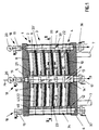
- a filter device 1 in the form of a filter press which has a plurality of horizontal filter elements 2, 3 and 4, each of which is circular in shape on its circumference and designed as a trub frame, and which have an axis that is coaxial with a vertical filter axis M and are held between a stationary upper cover 5 and a lower, vertically movable cover 6 which cooperates with pressing devices 7 for pressing the filter elements 2-4 against one another or for holding these filter elements together, which can be actuated, for example, hydraulically.
- the top filter element 2 arranged immediately below the cover 5 has a substantially circular disc-shaped ceiling wall 8, which rests with its top surface against the underside of the cover 5 and on the outer circumference of the filter element 2 in a protruding from the underside of the ceiling wall 8, concentrically surrounding the filter medium axis annular peripheral wall 9 merges.
- the lowermost filter element 4, which is arranged directly above the cover 6, has an annular bottom wall 10, the bottom of which rests flat against the top of the cover 6 and concentric on the outer circumference of the filter element 4 in a filter medium axis M projecting above the top of the bottom wall 10 enclosing annular projection 11 and in a projecting over the underside of the bottom wall 10, also concentrically surrounding the filter center axis M annular projection 12, which the latter engages to adjust and fix the filter element 4 on the cover 6 in an annular recess provided there.
- the bottom wall 10 merges into a circular cylindrical wall section 13 projecting above the top of this bottom wall and concentrically enclosing the filter center axis M, which surrounds a channel section 14 'open to the top and bottom of the filter element 4 and at its upper edge with a arranged essentially parallel to and at a distance from the bottom wall 10 and provided with respect to the filter center axis M over the wall section 13 radially outwardly projecting flange or wall section 15 which extends from the wall section 13 over part of the width of the between this wall section 13 and the projection 11 formed annular region of the filter element 4 and the bottom wall 10 extends.
- the annular wall section 15 has an outside diameter that is larger than the outside diameter of the wall section 13, but is considerably smaller than the outside diameter of the bottom wall 10 in the region of the projection 11.
- the filter elements 3 arranged between the filter elements 2 and 4 are each of the same design and differ from the filter element 4 only in that their bottom wall 10 on the outer circumference does not extend into the projection 12, but into one over the underside of the bottom wall 10 protruding and the peripheral wall 9 corresponding annular peripheral wall 16 which surrounds the filter center axis M with the same radial distance as the peripheral wall 9 and the projections 11 and 12.
- the top wall 8 and the bottom walls 10 of the filter elements 2, 3 and 4 are designed slightly conical in such a way that the top wall 8 and the bottom walls 10 in the direction from the filter center axis M to the outer circumference of the filter elements 2, 3 and 4, respectively, are inclined slightly upwards run.
- the top wall 8 and the bottom walls 10 can also be provided in horizontal planes.
- the lid 5 is formed by the channel sections 14 'unfiltrate channel 14 with a provided on the top of the lid 5 drain valve device 18 in connection, which has a pressure gauge 20 in addition to a sight glass 19.
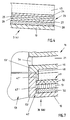
- each filter layer 23 consists of several layers, each of which is formed from a fabric made of corrosion-resistant material, preferably made of corrosion-resistant steel, and which are connected to one another by sintering to form a fabric arrangement.
- each filter layer 23 consists of a protective fabric 24, a fine-mesh filter fabric 25 arranged under this protective fabric 24, a distribution fabric 26 provided under the filter fabric 25, and a support fabric 27, of which the distribution fabric 26 has a coarse mesh than the filter fabric 25 and the support fabric 27 are coarser than the distribution fabric 26.
- the supporting fabric 27 lies on the top of a drainage fabric 28, which in the embodiment shown is part of the fabric arrangement welded into the respective filter element 3 or 4 and which in turn is supported with its underside on the top of the bottom wall 10 of this filter element 3 or 4 .
- the drainage fabric 28, which in particular is much more coarse-meshed in comparison to the support fabric 27, essentially serves to form an area below the fabric arrangement formed by the protective fabric 24, the filter fabric 25, the distributor fabric 26 and the support fabric 27, in which the filtered liquid (filtrate) can collect and from which this filtrate is removed and the is referred to as the filtrate collection area.
- the drainage fabric 28 can also be replaced by other measures which ensure a corresponding distance between the bottom wall 10 and the support fabric 27.
- the top of the bottom wall 10 is provided with, for example, knob-like or strip-like projections.
- the protective fabric 24, the filter fabric 25, the distributor fabric 26, the support fabric 27 and preferably also the drainage fabric 28 are connected to one another in a suitable manner and form a multilayer fabric arrangement from which the filter layers 23 (preferably including the drainage fabric) are cut by means of appropriate cuts 28) are manufactured.
- the filter elements 2, 3 and 4 are formed in one piece on their outer circumference or on the outer surface of their circumferential wall 9 or 16 with projections 30 projecting beyond this outer surface.
- three channel sections 33 ', 34' and 35 ' are introduced with a circular cross section, which are open on the top and on the bottom of these projections or the filter elements 2, 3 and 4.
- the arrangement of the channel sections 33 '- 35' is such that in a certain circumferential direction, that is, in the illustration chosen for FIG.
- channel section 35 ' Between these channel sections 33 'and 34' is on each projection 30 with a smaller radial distance from the filter center axis M, the channel section 35 'with a compared to the channel sections 33' and 34 'much smaller cross-section provided, in such a way that the two channel sections 35 'are diametrically opposite to each other with respect to the filter center axis M.
- the channel sections 33 ', 34' and 35 'of each filter element 2, 3 and 4 are each congruent with a corresponding channel section 33', 34 'and 35' of the rest Filter elements 2, 3 and 4, with which the channel sections 33 'of all filter elements form two parallel to the filter center axis M filtrate channels 33 for discharging the filtered liquid (filtrate), which also through the lower cover 6 through to an outlet 36 for each Continue filtrate.
- the channel sections 34 form two relative to the filter center axis M offset by 180 °, lying parallel to the filter center axis M and for cleaning the filter elements 2, 3 and 4 or the trub areas 22 serving flushing channels 34, which are through the lower cover 6
- a detergent rinse liquid
- the filtrate channels 33 and the flushing channels 34 also extend through the upper cover 5, where a drain valve device 18 with sight glass 19 and a pressure gauge 20 are also connected to the filtrate channels 33 and a drain valve device 18 with the sight glass 19 to the flushing channels 34, but without the pressure gauge 20 are connected.
- Each filter element 3 and 4 has in the projection 11 two slit-shaped openings 39, each opening into a channel section 33 'and on the inner surface of the projection 11 directly above the top of the bottom wall 10 in the filtrate collecting area, from the drainage fabric 28 below the supporting fabric 27 is formed.
- each filter element 2 and 3 on the inner surface of the peripheral wall 9 and 16 immediately below the top wall 8 and the bottom wall 10 has two pairs of two outlet openings for a detergent.
- these outlet openings are each formed by a channel 40 and 41, of which each channel 40 and 41 is open at one end on the inner surface of the peripheral wall 9 or 16 and with its other end in the associated channel section 34 'and thus opens into one of the two rinsing channels 14. As shown in FIGS.
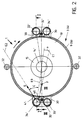
- all of the channels 40 of all filter elements 2 and 3 opening into a common flushing channel 34 lie with their longitudinal extension in a common vertical plane E1, which has a vertical axis, the filter center axis M and the axis of the relevant flushing channel 34 including and intersecting the plane E1 along the axis of the relevant rinsing channel 34, the reference plane E0 forms an angle a such that, given an assumed sense of rotation about the filter center axis M in accordance with the arrow A, the reference plane E0 follows the plane E1.
- the channels 40 are further inclined with respect to the horizontal so that the longitudinal extent of each channel 40 with the overlying top wall 8 or bottom wall 10 includes an acute angle b, which opens towards the filter center axis M.
- the angle a is only a few degrees in the illustrated embodiment.
- the channels 41 are based on the respective channel section 34 'similar to the channels 40 also inclined downward.
- the channels 41 of all filter elements 2 and 3 provided on a common rinsing channel 34 lie with their axes in a common vertical plane E2, which includes an acute angle c with the reference plane E0.
- the angle c is considerably larger than the angle a, but also significantly smaller than 90 ° and is, for example, of the order of 45 °.
- the angle c opens in the channels 41 of both rinsing channels 34 in the same circumferential direction, i.e. in the direction of arrow A. However, for the flushing function described below, it is not absolutely necessary that the channels 40 and 41 have the directions described above.
- outlet openings provided for the detergent on the inner surfaces of the peripheral wall 9 or 16, which for example can also be formed by nozzle openings inserted or screwed-in nozzles, generate detergent jets which correspond to the position of the axes of the bores 40 and 41 described above are oriented.
- each filter element 2 or 3 is also provided with two further channels 42, each of which is open at one end on the inner surface of the peripheral wall 9 or 16 directly below the ceiling wall 9 or the bottom wall 10 is and with its other end opens into a channel section 35 '.
- These channels 42 which connect the trub spaces 22 with the ventilation channels 35, are also inclined slightly obliquely downwards relative to the horizontal, corresponding to the channels 40 and 41.
- a precoat layer 43 formed by this filter aid is built up in the usual manner in a precoat phase using at least one filter aid on the top of the filter layers 23.
- this is also carried out in the usual way Filtration, in which the unfiltrate is fed in via arrow B via inlet 17 and the filtrate is discharged via two outlets 36, which are provided below cover 6 and are preferably connected to one another, according to arrow C.
- the unfiltrate passes through the inlet 17, through the unfiltrate channel 14 and through the distributor chambers 21 into the individual trub spaces 22, in which the liquid the precoat layer 43 and the filter layer 23 then separate the trub or solids on or in the precoat layer 43 flows through, so that the filtrate can flow through the respective filtrate collecting area formed by the drainage fabric 28 and through the openings 39 into the filtrate channels 33.
- the unfiltrate when the unfiltrate enters the unfiltrate channel 14 into the distribution chambers 21, the unfiltrate is deflected by 90 ° in such a way that the direction of flow of this unfiltrate after entering each distribution chamber 21 is directed radially outwards with respect to the filter center axis M.
- annular cross section of the distribution chambers 21 increases their effective cross-section with increasing distance from the filter center axis M, an increasing slowdown in the flow rate of the unfiltrate is achieved within the distribution chambers 21, so that this is supplied to the inlet 17 even at a relatively high quantity per unit time of unfiltrate when it emerges from the respective distribution chamber 21 into the associated turbidity chamber 22 has only a very low flow velocity, with a pronounced flow component directed radially away from the filter medium axis M.
- this entry area through the wall sections 13 and 15 lies at a distance above the respective filter layer 23 and the precoat layer 43 formed thereon, ie the filter layer 23 and the precoat layer 43, so to speak, in the "flow shadow", at least the radial flow component of that entering the turbidity chamber 22 Are unfiltrate and the latter only after reducing the flow velocity and after another redirection by about 90 ° down into the precoat 43, is ensured even at a relatively high volume output (per unit of time supplied amount of unfiltrate) that one for the filter layer 23 Depth filtration suitable precoat layer 43 is deposited in a uniform structure or composition and this precoat layer 43 is retained even during the actual filtration and is not lost or becomes unusable in certain areas of the filter layer 23 due to whirling or washing up.
- the filter device can be cleaned easily and without any problems using a suitable detergent.
- the detergent is supplied to the two rinsing channels 34 at a corresponding pressure via the inlets 37, so that the detergent then flows into the trub spaces 22 as rinsing agent jets at the outlet openings connected to the rinsing channels 34 and, in the embodiment shown, formed by the channels 40 and 41 occurs, as indicated by the arrows F and G in FIG.
- the detergent emerging from the channels 41 or from the corresponding outlet openings in the direction of arrow G causes the dissolved constituents of the precoat 43 (filter residues) or the filter cake to rotate within the respective turbidity chamber 22 in the direction of arrow A, while at the same time detergent emerging from the channels 40 or from corresponding outlet openings in the direction of the arrow F is a substantially radially inward directed detergent jet or generated countercurrent, which leads to a crushing of possibly larger constituents or lumps of the detached filter residues and thus to a complete dissolution of the filter residues, which can then be discharged together with the detergent through the unfiltrate channel 14 and via the inlet 17 .
- the filter device 1a shown in FIG. 5 differs from the filter device 1 essentially only in that the filter elements 3a and 4a used there, which correspond to the filter elements 3 and 4 in terms of their arrangement, function and other configuration , instead of the wall sections 13 and 15 have a ring 45 concentrically enclosing the filter center axis M and connected or integrally formed with the respective bottom wall 10, the outside diameter of which is approximately equal to the outside diameter of the wall sections 15 of the filter elements 3 and 4 of the filter device 1.
- Each ring 45 in turn forms with its inner surface a channel section 14 'and with its ring surface 45' together with the underside of the top wall 8 of the filter element 2 and the bottom wall 10 of the overlying filter element 3a, the annular distribution chamber 21st
- Fig. 6 shows a filter device 1b, which differs from the filter device 1 essentially in that instead of the filter elements 3 and 4 together with the filter element 2, the filter elements 3b and 4b are used, which in terms of their arrangement and function of the filter elements 3 and 4 correspond to the filter device 1.
- the filter elements 3b and 4b are each formed in two parts, that is to say they each consist of an upper additional disk 46 and a lower, disk-like part which forms the bottom wall 10 of the respective filter element 3b or 4b and, in turn, on the outer circumference adjoining the bottom wall 10, projecting above the top of the bottom wall, ring-like projection 11 and over the bottom of the bottom wall 10 projecting peripheral wall 16 (in the case of the filter elements 3b) or the projection 12 projecting beyond the underside of the base wall 10 (in the case of the filter element 4b).
- each filter element 3b or 4b is provided with a circular-cylindrical flange 47 projecting above the upper side of the bottom wall 10, on which the additional disk 46 is detachably fastened, in such a way that this disk is connected to one over the Underside of the disk 46 projecting annular flange 48 encloses the flange 47 in the region of a section 47 'with a reduced outer diameter.
- the filter layer 49 corresponding to the filter layer 23 is formed in the filter device 1b from an upper layer of a carrier layer, filter membrane or filter fabric 50 which is customary for the precoat layer 43 and which on the inner edge of the filter elements 3b and 4b between the flange 48 and a shoulder 47 ⁇ of the flange 47 and on the outer edge of the filter elements 3b or 4b between the ring-like projection 11 of the respective filter element and the peripheral wall 9 or 16 of the filter element 2 or 3b lying above it is tightly clamped.
- the filter fabric 50 rests on a support fabric 51 and the latter on a drainage fabric 52 supported against the top of the bottom wall 10.
- the disks 46 and the filter elements 2, 3b and 4b enclose a coaxial pipe section 53 ', which forms the unfiltrate channel 53 connected to the inlet 17 and also extends into the covers 5 and 6.
- the pipe section 53 ' is formed by a plurality of closely adjacent pipe sections, which are then attached either to the disks 46 or to the filter elements 2, 3b, 4b, such a pipe section being then also provided on the cover 6 and 5, respectively.
- the pipe section 53 ' has a plurality of openings 54, of which several each open into each distribution chamber 21, each between the top of a disc 46 and the ceiling wall 8 or
- the filter device 1b corresponds to the filter device 1.
- This also applies to the function and effect of the distributor chambers 21, with the disks being removable from the filter elements 3b and 4b 46 and because of the possibility of better access to the top of the bottom walls 10 of these filter elements, for example for the installation of the filter layer 49, it is possible to choose an outer diameter for the disks 46 which is larger than the outer diameter of the wall sections 15 or the rings 45 in the filter devices 1 and 1a, with which the effect of the distribution chambers 21 can be significantly improved.
- the filter devices 1 a and 1 b also have the basic advantage over the filter device 1 that the respective filter layer 23 or 49 or the layers forming these filter layers can each be applied to the bottom walls 10 as a one-piece cut.
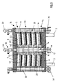
- FIG. 8 and 9 show a filter device 1c, which in turn is designed as a filter press and consists of the trub frame or filter elements 3c and 4c arranged between the covers 5c and 6c.
- the filter device 1c differs from the filter device 1 essentially in that the filtrate channel 55 is provided in the center of the filter device 1c coaxially with the filter center axis M, and in that several unfiltrate channels 56 extending parallel to the filter center axis M are provided around this filtrate channel 55 are in turn enclosed by the trub rooms.
- the rinsing channels 34 and the ventilation channels 35 are again provided on the outside of the filter elements 3c and 4c.
- the uppermost filter element 3c which directly adjoins the underside of the cover 5c, which on this underside surrounds the filter center axis M. is provided, as well as the further filter elements 3c adjoining at the bottom, consists of a circular disk-shaped bottom wall 58 which is arranged in a horizontal plane and which, on the outside of the filter element 3c, merges into an annular circumferential wall 59 which concentrically surrounds the filter center axis M and which passes over the The top and bottom of the bottom wall 58 protrude. In the middle of each filter element 3c, the bottom wall 58 merges into a ring 60 projecting over the top of this bottom wall 58, which has a channel section 55 'open to the top and bottom of the filter element 3c.
- each ring 60 is provided on its upper side with an annular groove 61 concentrically enclosing the filter medium axis M and open toward the upper side, over the edge of which, closer to the filter medium axis M, the ring 60 protrudes with a section 60 'with a reduced cross section and at whose the On the edge 60 of the filter center axis M, a flange or wall section 62 protruding radially outward from this ring is provided on the ring 60 and is provided parallel to and at a distance above the bottom wall 58 of the filter element 3c concerned.
- the outer diameter of each disk-shaped wall section 62 is smaller than the diameter that the relevant filter element 3c has on the inner surface of the peripheral wall 59.
- each filter element 3c In the ring 60 of each filter element 3c are distributed around the filter center axis M channel sections 56 'which are each open on the underside of the filter element 3c and open into the groove 61 on the top of the filter element 3c.
- each filter element 3c In the area of the ring 60, each filter element 3c also has an annular flange 63 on its underside, which comprises the section 60 'of the filter element 3c or 4c below it.
- the flange 63 can also be interrupted in the region of the channel sections 56 '.
- the filter element 4c differs from the filter elements 3c only in that the part of the circumferential wall 59 protruding from the underside of the bottom wall 58 is omitted on the filter element 4c, so that the filter element 4c lies flat with the underside of its bottom wall 59 against the top of the cover 6c .
- the filter elements 3c and 4c are in turn formed with the projections 30 corresponding projections 64, which have the channel sections 34 '.
- the channel sections 34 ', 55' and 56 'of the individual filter elements 3c and 4c are congruent with each other, so that the channel sections 34' the continuous flushing channel 34, the channel sections 55 'the continuous filtrate channel 55 and the channel sections 56 'form a plurality of continuous unfiltrate channels 56, of which a total of eight are provided around the filtrate channel 55 in the embodiment shown.
- the rinsing channel 34 which in this embodiment again has the inlet 37 provided under the cover 6c and is connected to the drain valve device 18 provided on the upper side of the cover 5c with a pressure gauge 20, the channels 40 and 41, in turn, open out 8 only the channels 40 are shown.
- These channels 40 and 41 are also provided in the cover 5c and open there on the one hand in the recess 57 and on the other hand in the channel section 34 'also formed in the cover 5c.
- An outlet 65 is provided for the filtrate channel 55 on the underside of the cover 6c. At its upper end, the filtrate channel 55 is connected to a drain valve device 18 with a pressure gauge 20 provided there. On the underside of the lid 6c there is also an inlet 66 which is connected to a groove-like annular channel 67 which is formed in the lid 6c and which is open towards the top of this lid and which in turn establishes a connection to the individual unfiltrate channels 56.
- each filter element 3c or 4c forms between itself and the overlying boundary wall, which in the uppermost filter element from the bottom surface of the recess 57 in the cover 5c and in the filter elements below it from the underside of the bottom wall 58 of the overlying filter element 3c, an annular distributor chamber 68, which corresponds to the function and effect of the distributor chamber 21.
- each filter element 3c or 4c an annular trub space 69 is again formed, essentially below the respective wall section 62 and above the filter layer 23 supported on the top of the respective bottom wall 58
- Filtrate collecting area of the drainage tissue 28 collecting filtrate into the filtrate channel 55 are in the area of the ring 60 of each filter element 3c or 4c offset from the channel sections 56 ', substantially radially to the filter center axis M bores or channels 70, each with one end in the filtrate collecting area formed by the drainage fabric 28 and the other end open into the filtrate channel 55.
- the individual filter elements 3c and 4c in turn lie in the area of their peripheral walls 59, in the area of their rings 60 and in the area of their projections 64 using sealing rings tightly against one another and also tightly against the covers 5c and 6c. In the illustrated embodiment are on the rings 60 or at the local connection or.
- two concentric sealing rings 71 and 72 are provided with an intermediate groove 73 concentrically surrounding the filter medium axis M, which the latter opens into a drainage channel 74 running parallel to the filter center axis M, so that despite the narrow spatial arrangement between the unfiltrate channels 56 and the filtrate channel 55, if a sealing ring 71 or 72 unfiltrate leaks, unfiltrate cannot get directly into the filtrate channel 55, but instead flows out through the drainage channel 74 open at the bottom of the cover 6c.
- the filter device 1c also offers the same advantages as described above in connection with the filter device 1 with regard to reducing the flow rate of the unfiltrate in the distribution chambers 68 and with regard to the cleaning or discharge of the filter residues.
Landscapes
- Chemical & Material Sciences (AREA)
- Chemical Kinetics & Catalysis (AREA)
- Filtration Of Liquid (AREA)
- Filtering Of Dispersed Particles In Gases (AREA)
Claims (25)
- Dispositif filtrant comprenant plusieurs zones de filtration superposées en direction d'un axe de filtre vertical (M) et qui sont orientées pour l'essentiel horizontalement, auxquelles sont coordonnés au moins un canal commun de produit non filtré (14; 53; 56) pour l'amenée d'un liquide à filter (produit non filtré) ainsi qu'au moins un canal commun de filtrat (33; 55) pour l'évacuation du liquide filtré (filtrat) et qui comportent chacune au moins une couche filtrante (23; 49) prévue sur un élément filtrant (3, 4; 3a, 4a; 3b, 4b; 3c, 4c), qui sert au dépôt d'au moins une couche déposée formée par au moins un adjuvant de filtration et sépare une zone de rassemblement de filtrat, laquelle débouche dans le canal de filtrat (33; 55), d'un espace de dépôt (22; 69) situé au-dessus, et comprenant une chambre de répartition annulaire (21; 68) prévue pour chaque zone de filtration et entourant l'axe (M) du filtre, chambre qui débouche à sa périphérie, à une première distance radiale relativement grande de l'axe (M) du filtre, au droit d'une ouverture de sortie, dans l'espace de dépôt (22; 69) et présente, à une seconde distance radiale plus petite de l'axe (M) du filtre, au moins une ouverture d'entrée pour le produit non filtré, ouverture d'entrée qui communique avec le canal de produit non filtré (14; 53; 56), la sortie du canal de produit non filtré (14 ; 53 ; 56), entourée des zones de filtration étant prévue dans la région de l'axe (M) du filtre, dispositif caractérisé en ce que la direction d'écoulement à partir du canal de produit non filtré (14; 53; 56) dans la chambre de répartition (21; 68), à l'intérieur même de la chambre de répartition et à partir de la chambre de répartition dans l'espace de dépôt (22; 69) est radiale, l'ouverture de sortie étant exempte de rétrécissements de la section d'écoulement.
- Dispositif filtrant selon la revendication 1, caractérisé en ce que, en cas de réalisation du dispositif filtrant (1; 1a; 1b; 1c) comme un filtre-presse, les éléments filtrants (2, 3, 4; 3a, 4a, 3b, 4b; 3c, 4c) sont des cadres de dépôt horizontaux placés entre un couvercle supérieur et un couvercle inférieur (5, 6; 5c, 6c), et qu'un espace de dépôt (22; 69), fermé vers l'extérieur, est formé chaque fois entre deux éléments filtrants (2, 3, 4; 2, 3a, 4a; 2, 3b, 4b) qui se suivent en direction de l'axe (M) du filtre, ainsi que, éventuellement, entre le dessous du couvercle supérieur (5) et l'élément filtrant (3c) sous-jacent.
- Dispositif filtrant selon la revendication 1 ou 2, caractérisé en ce que les éléments filtrants (3, 4; 3a, 4a; 3b, 4b; 3c, 4c), présentant les couches filtrantes (23; 49), possèdent chacun une paroi de fond (10; 58) essentiellement horizontale et entourant l'axe (M) du filtre, sur laquelle est prévue la couche filtrante (23; 49) correspondante, et que chacun de ces éléments filtrants (3, 4; 3a, 4a; 3b, 4b; 3c, 4c) présente, à distance au-dessus de sa paroi de fond (10; 58), une première surface de délimitation (15; 45', 46; 62) entourant concentriquement l'axe (M) du filtre et qui forme entre elle et une seconde surface de délimitation (8; 10; 5c, 58) située au-dessus, la chambre de répartition (21; 68).
- Dispositif filtrant selon la revendication 3, caractérisé en ce que la seconde surface de délimitation est formée, dans le cas de la chambre de répartition (21; 68) située tout à fait en haut, par le côté inférieur d'une paroi de dessus (8) d'un élément filtrant (2) situé au-dessus ou par le dessous du couvercle supérieur (5c) et, dans le cas de chacune des chambres de répartition (21; 68) sous-jacentes, par le côté inférieur de la paroi de fond (10; 58) de l'élément filtrant (3; 3a; 3b; 3c) situé au-dessus.
- Dispositif filtrant selon la revendication 3 ou 4, caractérisé en ce que la première surface de délimitation est formée par la surface d'extrémité (45') d'une saillie annulaire (45) entourant concentriquement l'axe (M) du filtre et dépassant du côté supérieur de la paroi de fond (10) de l'élément filtrant (3a), ou par le côté supérieur d'une portion de paroi annulaire (15; 46; 62) s'étendant radialement vers l'extérieur, par rapport à l'axe (M) du filtre, à partir d'une telle saillie annulaire (13; 47; 60).
- Dispositif filtrant selon la revendication 5, caractérisé en ce que la portion de paroi (15; 46; 62) formant la première surface de délimitation de la chambre de répartition (21; 68) correspondante, s'étend, dans la direction allant de l'axe (M) du filtre vers un bord extérieur des éléments filtrants (3, 4; 3b, 4b; 3c, 4c), sur une partie de la largeur de la paroi de fond (10; 58) sous-jacente.
- Dispositif filtrant selon la revendication 5 ou 6, caractérisé en ce que le diamètre extérieur de la saillie (45) ou de la portion de paroi (15; 46; 62) formant la première surface de délimitation de la chambre de répartition (21; 68) correspondante, est plus petit que le diamètre extérieur de la paroi de fond (10; 58) sous-jacente en forme d'anneau circulaire.
- Dispositif filtrant selon une des revendications 5 à 7, caractérisé en ce que la portion de paroi formant la première surface de délimitation de la chambre de répartition (21) correspondante est un disque (46) fixé amovible à une partie de l'élément filtrant (3b, 4b) comprenant la paroi de fond (10).
- Dispositif filtrant selon la revendication 1, caractérisé en ce que les ouvertures d'entrée par lesquelles le canal de produit non filtré (14) débouche dans la chambre de répartition (21), sont formées du fait que chaque élément filtrant (3, 4; 3a, 4a; 3b, 4b) est disposé, dans sa région entourant l'axe (M) du filtre ou le canal de produit non filtré (14), à distance axiale de l'élément filtrant (2, 3; 2, 2a; 2, 3b) situé au-dessus ou du dessous d'un couvercle (5) situé au-dessus.
- Dispositif filtrant selon la revendication 1 ou 9, caractérisé en ce qu'au moins un canal de filtrat (33) est prévu avec un décalage radial par rapport à l'axe (M) du filtre sur la surface périphérique extérieure des éléments filtrants (2, 3, 4; 3a, 4a; 3b, 4b).
- Dispositif filtrant selon une des revendications 1 à 8, caractérisé en ce que le canal de filtrat (55) est prévu coaxialement à l'axe (M) du filtre et qu'au moins un canal de produit non filtré (56) est disposé, avec un décalage par rapport à l'axe (M) du filtre, à proximité du canal de filtrat (55), de manière que ce canal de produit non filtré soit également entouré des zones de filtration.
- Dispositif filtrant selon la revendication 11, caractérisé en ce que plusieurs canaux de produit non filtré (56) sont répartis autour du canal de filtrat (55).
- Dispositif filtrant selon la revendication 11 ou 12, caractérisé en ce que les éléments filtrants (3c, 4c) se raccordent de façon étanche les uns aux autres, ainsi qu'au couvercle supérieur et/ou au couvercle inférieur (5c, 6c), dans leur région centrale entourant le canal de filtrat (55).
- Dispositif filtrant selon la revendication 13, caractérisé en ce que, dans la région de raccordement entre deux éléments filtrants (3c, 4c) et/ou entre un élément filtrant (3c, 4c) et un couvercle (5c, 6c), on a prévu chaque fois deux joints annulaires (71, 72) ayant des diamètres différents et entourant concentriquement l'axe (M) du filtre, ainsi que, entre ces joints, une rainure annulaire (73) qui débouche dans au moins un canal de drainage (74) orienté parallèlement à l'axe (M) du filtre.
- Dispositif filtrant selon une des revendications 1 à 14, caractérisé par au moins un canal de lavage vertical (34) qui est commun à toutes les zones de filtration et communique avec au moins une ouverture de sortie de fluide de lavage (40, 41) prévue sur chaque zone de filtration.
- Dispositif filtrant selon la revendication 15, caractérisé en ce qu'au moins une ouverture de sortie de fluide de lavage (40, 41) pour chaque zone de filtration est prévue au-dessus de la couche filtrante (23, 49) de cette zone de filtration et est disposée par son axe de manière qu'elle produise un jet de fluide de lavage (F, G) dirigé obliquement vers le bas sur la couche filtrante (23, 49) de la zone de filtration.
- Dispositif filtrant selon la revendication 15 ou 16, caractérisé en ce que les axes d'au moins une partie des ouvertures de sortie de fluide de lavage (41) sont situés dans un premier plan vertical (E2) qui renferme avec un plan de référence (E0) contenant l'axe (M) du filtre ainsi que l'axe du canal de lavage (34), un premier angle (c) plus petit que 90°, de préférence un angle inférieur à 45°.
- Dispositif filtrant selon la revendication 17, caractérisé en ce que, pour chaque zone de filtration, on a prévu au moins deux ouvertures de sortie de fluide de lavage (40, 41), dont une première (41) est disposée par son axe dans le premier plan vertical (E2) et dont une deuxième ouverture de sortie de fluide de lavage (40) est disposée par son axe dans un deuxième plan vertical (E1), ce dernier étant orienté radialement ou presque radialement par rapport à l'axe (M) du filtre ou renfermant avec le plan de référence (E0) vertical un deuxième angle (a) nettement plus petit que 90°.
- Dispositif filtrant selon la revendication 18, caractérisé en ce que le premier angle (c) et le deuxième angle (a) s'ouvrent vers des côtés différents du plan de référence (E0).
- Dispositif filtrant selon une des revendications 16 à 19, caractérise en ce que deux canaux de lavage (34) sont prévus avec un décalage mutuel de 180° autour de l'axe (M) du filtre.
- Dispositif filtrant selon une des revendications 1 à 20, caractérisé en ce qu'au moins un canal de produit non filtré (14; 54; 56) et/ou au moins un canal de filtrat (33; 55) et/ou au moins un canal de lavage (34) sont formés chaque fois par des tronçons de canal (14', 33', 34'; 53', 55', 56') ménagés dans les éléments filtrants (2, 3, 4; 3a, 4a; 3b, 4b; 3c, 4c).
- Dispositif filtrant selon une des revendications 1 à 21, caractérisé en ce que la zone de rassemblement de filtrat prévue sous chaque couche filtrante (23), est formée par une toile de drainage (28).
- Dispositif filtrant selon une des revendications 1 à 22, caractérisé en ce que les couches filtrantes (23) sont constituées chacune par un système de toiles (24 - 28), comprenant de préférence aussi la toile de drainage (28), qui est formé de plusieurs couches ou strates constituées chacune d'au moins une toile et dans lequel de préférence une partie au moins des toiles sont reliées entre elles.
- Dispositif filtrant selon la revendication 23, caractérisé en ce que les systèmes de toiles (24 - 28) sont soudés chaque fois dans les éléments filtrants (3, 4; 3a, 4a; 3c, 4c).
- Dispositif filtrant selon une des revendications 1 à 24, caractérisé en ce que les éléments filtrants (2, 3, 4; 3a, 4a; 3b, 4b; 3c, 4c) possèdent au moins à l'intérieur une section droite circulaire.
Applications Claiming Priority (2)
| Application Number | Priority Date | Filing Date | Title |
|---|---|---|---|
| DE3900934 | 1989-01-14 | ||
| DE3900934A DE3900934A1 (de) | 1989-01-14 | 1989-01-14 | Filtervorrichtung |
Publications (3)
| Publication Number | Publication Date |
|---|---|
| EP0379054A2 EP0379054A2 (fr) | 1990-07-25 |
| EP0379054A3 EP0379054A3 (en) | 1990-08-16 |
| EP0379054B1 true EP0379054B1 (fr) | 1994-08-03 |
Family
ID=6372062
Family Applications (1)
| Application Number | Title | Priority Date | Filing Date |
|---|---|---|---|
| EP90100480A Expired - Lifetime EP0379054B1 (fr) | 1989-01-14 | 1990-01-11 | Dispositif filtrant |
Country Status (5)
| Country | Link |
|---|---|
| US (1) | US5069791A (fr) |
| EP (1) | EP0379054B1 (fr) |
| JP (1) | JPH02273506A (fr) |
| DE (2) | DE3900934A1 (fr) |
| ES (1) | ES2058607T3 (fr) |
Families Citing this family (16)
| Publication number | Priority date | Publication date | Assignee | Title |
|---|---|---|---|---|
| US5637216A (en) * | 1991-10-04 | 1997-06-10 | Rosenmund Ag, A Swiss Corporation | Filter matting for a reversible-flow filter |
| DE4309366C1 (de) * | 1993-03-23 | 1994-04-21 | Thomas Handtmann | Filterträger |
| DE10065258A1 (de) * | 2000-12-29 | 2002-07-18 | Seitzschenk Filtersystems Gmbh | Modul zum Behandeln von Fluiden und Verfahren zur Herstellung solcher Module |
| DE10217262A1 (de) * | 2002-04-18 | 2003-11-06 | Pall Corp | Filtermodul und Verfahren zur Herstellung eines gefüllten Filtermoduls |
| DE10340366B4 (de) * | 2003-09-02 | 2008-12-18 | Khs Ag | Filtervorrichtung |
| US7390403B2 (en) * | 2004-03-19 | 2008-06-24 | Millipore Corporation | Prefilter system for biological systems |
| US20050279695A1 (en) * | 2004-06-17 | 2005-12-22 | Millipore Corporation | Disposable integral filter unit |
| US20050279694A1 (en) * | 2004-06-17 | 2005-12-22 | Gregory Straeffer | Disposable integral filter unit |
| EP1609517B1 (fr) * | 2004-06-17 | 2009-04-01 | Millipore Corporation | Module de filtration jetable |
| US7410569B1 (en) | 2005-11-18 | 2008-08-12 | Turhan A. Tilev | Filtration system for metalworking fluids |
| DE102007027033B4 (de) * | 2007-06-08 | 2009-05-07 | Larox Oyj | Verfahren zum Filtern einer Suspension und Filtervorrichtung |
| DE102007038828A1 (de) | 2007-08-16 | 2009-02-19 | Khs Ag | Mischung aus Filterhilfsmitteln zur Verwendung bei der Anschwemmfiltration sowie Verfahren zur Anschwemmfiltration von Flüssigkeiten |
| DE102010000922B3 (de) * | 2010-01-14 | 2011-06-30 | Achenbach Buschhütten GmbH, 57223 | Horizontalplattenfilter |
| JP2013188673A (ja) * | 2012-03-13 | 2013-09-26 | Toshiba Corp | フッ素回収装置、フッ素回収システム及びフッ素回収方法 |
| US11400393B2 (en) * | 2017-11-29 | 2022-08-02 | Maagan Filtration Aca Ltd. | Filtration system |
| US20230294047A1 (en) * | 2022-03-16 | 2023-09-21 | Engi-Mat Co. | Multilayered wire mesh-supported membranes for separation applications |
Family Cites Families (11)
| Publication number | Priority date | Publication date | Assignee | Title |
|---|---|---|---|---|
| US984704A (en) * | 1910-03-31 | 1911-02-21 | John Rarick | Automatic household-filter. |
| FR629059A (fr) * | 1927-02-12 | 1927-11-03 | Sucrerie Centrale De Cambrai | Dispositif d'arrosage des disques filtrants |
| DE749333C (de) * | 1942-01-22 | 1944-11-21 | Altoelreiniger, insbesondere fuer Kraftfahrzeuge | |
| CH322613A (de) * | 1953-02-28 | 1957-06-30 | Seitz Werke Gmbh | Filter |
| GB833395A (en) * | 1958-10-24 | 1960-04-21 | Moatti Georges | Improvements in or relating to oil filters |
| US3206034A (en) * | 1962-11-20 | 1965-09-14 | Ametek Inc | Filter |
| GB1021331A (en) * | 1963-01-01 | 1966-03-02 | Wolfgang Bernhard Hoelscher | Horizontal plate filter |
| US3285417A (en) * | 1964-01-16 | 1966-11-15 | Industrial Filter Pump Mfg Co | Filter sluicing method and apparatus |
| DE1278405B (de) * | 1966-03-26 | 1968-09-26 | Seitz Werke Gmbh | Kesselfilter mit im Kesselboden angeordnetem zentralem Truebezulauf |
| AT269901B (de) * | 1966-06-07 | 1969-04-10 | Inst Chemieanlagen | Apparat zur Filtration von Flüssigkeiten |
| US3443697A (en) * | 1967-03-23 | 1969-05-13 | Ametek Inc | Plural,inverted,cup-shaped filter elements |
-
1989
- 1989-01-14 DE DE3900934A patent/DE3900934A1/de not_active Withdrawn
-
1990
- 1990-01-11 DE DE59006650T patent/DE59006650D1/de not_active Expired - Fee Related
- 1990-01-11 EP EP90100480A patent/EP0379054B1/fr not_active Expired - Lifetime
- 1990-01-11 US US07/463,382 patent/US5069791A/en not_active Expired - Fee Related
- 1990-01-11 ES ES90100480T patent/ES2058607T3/es not_active Expired - Lifetime
- 1990-01-12 JP JP2003721A patent/JPH02273506A/ja active Pending
Also Published As
| Publication number | Publication date |
|---|---|
| DE59006650D1 (de) | 1994-09-08 |
| JPH02273506A (ja) | 1990-11-08 |
| US5069791A (en) | 1991-12-03 |
| EP0379054A3 (en) | 1990-08-16 |
| DE3900934A1 (de) | 1990-07-19 |
| EP0379054A2 (fr) | 1990-07-25 |
| ES2058607T3 (es) | 1994-11-01 |
Similar Documents
| Publication | Publication Date | Title |
|---|---|---|
| EP0379054B1 (fr) | Dispositif filtrant | |
| EP0038042B1 (fr) | Installation de filtration | |
| AT396753B (de) | Filtervorrichtung | |
| WO1993023139A1 (fr) | Dispositif de filtrage | |
| EP1150760B1 (fr) | Filtre a modules ayant au moins une amenee pour le produit non filtre et une evacuation pour le produit filtre et comportant au moins un module filtrant | |
| EP0650753B2 (fr) | Dispositif de filtration à nettoyage par contre-courant | |
| EP0366903B1 (fr) | Buse filtrante comportant des segments annulaires | |
| DE2502669C2 (de) | Vorrichtung zum abscheiden und austragen von feststoffteilchen aus einer unter druck stehenden fluessigkeit | |
| EP0026270B1 (fr) | Filtre de rinçage à contre-courant | |
| EP0789611B1 (fr) | Dispositif a filtres en forme de bougie utilise pour la filtration de biere | |
| DE3430992C2 (de) | Filtervorrichtung | |
| DE4337187C1 (de) | Rückspülbare Filtereinrichtung | |
| DE10001907A1 (de) | Filtervorrichtung | |
| DE4424232C2 (de) | Rückspülbare Filtereinrichtung | |
| EP0655934B1 (fr) | Filtre sous pression | |
| EP2879774A1 (fr) | Filtre-presse à plateaux | |
| DE2106077C3 (de) | Röhrenfilterpresse | |
| DE1205493B (de) | Filterelement fuer Vorrichtungen zum Filtrieren von Fluessigkeiten | |
| DE4307472A1 (de) | Filter für Flüssigkeiten, Pasten oder andere hochviskose Medien | |
| DE19621473C1 (de) | Schleudertrommel einer Zuckerzentrifuge | |
| DE3425540A1 (de) | Einstellbarer filter | |
| DE4127477A1 (de) | Filtervorrichtung | |
| DE2452524A1 (de) | Scheibenfilterelement zur filtration von fluessigkeiten, insbesondere unter verwendung von kieselgur | |
| EP1464373B1 (fr) | Elément filtrant pourvu d' un support et utilisation de l' élément support pour supporter le milieu filtrant | |
| EP3967662A1 (fr) | Cartouche filtrante et dispositif filtrant |
Legal Events
| Date | Code | Title | Description |
|---|---|---|---|
| PUAI | Public reference made under article 153(3) epc to a published international application that has entered the european phase |
Free format text: ORIGINAL CODE: 0009012 |
|
| PUAL | Search report despatched |
Free format text: ORIGINAL CODE: 0009013 |
|
| AK | Designated contracting states |
Kind code of ref document: A2 Designated state(s): CH DE ES FR GB IT LI |
|
| AK | Designated contracting states |
Kind code of ref document: A3 Designated state(s): CH DE ES FR GB IT LI |
|
| 17P | Request for examination filed |
Effective date: 19901214 |
|
| 17Q | First examination report despatched |
Effective date: 19920514 |
|
| RAP1 | Party data changed (applicant data changed or rights of an application transferred) |
Owner name: KHS MASCHINEN- UND ANLAGENBAU AKTIENGESELLSCHAFT |
|
| GRAA | (expected) grant |
Free format text: ORIGINAL CODE: 0009210 |
|
| AK | Designated contracting states |
Kind code of ref document: B1 Designated state(s): CH DE ES FR GB IT LI |
|
| ITF | It: translation for a ep patent filed |
Owner name: BARZANO' E ZANARDO ROMA S.P.A. |
|
| REF | Corresponds to: |
Ref document number: 59006650 Country of ref document: DE Date of ref document: 19940908 |
|
| ET | Fr: translation filed | ||
| GBT | Gb: translation of ep patent filed (gb section 77(6)(a)/1977) |
Effective date: 19940816 |
|
| REG | Reference to a national code |
Ref country code: ES Ref legal event code: FG2A Ref document number: 2058607 Country of ref document: ES Kind code of ref document: T3 |
|
| PGFP | Annual fee paid to national office [announced via postgrant information from national office to epo] |
Ref country code: DE Payment date: 19941117 Year of fee payment: 6 |
|
| PGFP | Annual fee paid to national office [announced via postgrant information from national office to epo] |
Ref country code: FR Payment date: 19941201 Year of fee payment: 6 |
|
| PGFP | Annual fee paid to national office [announced via postgrant information from national office to epo] |
Ref country code: CH Payment date: 19941230 Year of fee payment: 6 |
|
| PGFP | Annual fee paid to national office [announced via postgrant information from national office to epo] |
Ref country code: ES Payment date: 19950105 Year of fee payment: 6 |
|
| PGFP | Annual fee paid to national office [announced via postgrant information from national office to epo] |
Ref country code: GB Payment date: 19950106 Year of fee payment: 6 |
|
| PLBE | No opposition filed within time limit |
Free format text: ORIGINAL CODE: 0009261 |
|
| STAA | Information on the status of an ep patent application or granted ep patent |
Free format text: STATUS: NO OPPOSITION FILED WITHIN TIME LIMIT |
|
| 26N | No opposition filed | ||
| PG25 | Lapsed in a contracting state [announced via postgrant information from national office to epo] |
Ref country code: GB Effective date: 19960111 |
|
| PG25 | Lapsed in a contracting state [announced via postgrant information from national office to epo] |
Ref country code: ES Free format text: LAPSE BECAUSE OF NON-PAYMENT OF DUE FEES Effective date: 19960112 |
|
| PG25 | Lapsed in a contracting state [announced via postgrant information from national office to epo] |
Ref country code: LI Effective date: 19960131 Ref country code: CH Effective date: 19960131 |
|
| GBPC | Gb: european patent ceased through non-payment of renewal fee |
Effective date: 19960111 |
|
| REG | Reference to a national code |
Ref country code: CH Ref legal event code: PL |
|
| PG25 | Lapsed in a contracting state [announced via postgrant information from national office to epo] |
Ref country code: FR Effective date: 19960930 |
|
| PG25 | Lapsed in a contracting state [announced via postgrant information from national office to epo] |
Ref country code: DE Effective date: 19961001 |
|
| REG | Reference to a national code |
Ref country code: FR Ref legal event code: ST |
|
| REG | Reference to a national code |
Ref country code: ES Ref legal event code: FD2A Effective date: 19990201 |
|
| PG25 | Lapsed in a contracting state [announced via postgrant information from national office to epo] |
Ref country code: IT Free format text: LAPSE BECAUSE OF NON-PAYMENT OF DUE FEES;WARNING: LAPSES OF ITALIAN PATENTS WITH EFFECTIVE DATE BEFORE 2007 MAY HAVE OCCURRED AT ANY TIME BEFORE 2007. THE CORRECT EFFECTIVE DATE MAY BE DIFFERENT FROM THE ONE RECORDED. Effective date: 20050111 |