EP0517101B1 - Verfahren und Vorrichtung zur Vorbereitung einer Bedruckstoffbahnrolle für den fliegenden Rollenwechsel - Google Patents
Verfahren und Vorrichtung zur Vorbereitung einer Bedruckstoffbahnrolle für den fliegenden Rollenwechsel Download PDFInfo
- Publication number
- EP0517101B1 EP0517101B1 EP92109010A EP92109010A EP0517101B1 EP 0517101 B1 EP0517101 B1 EP 0517101B1 EP 92109010 A EP92109010 A EP 92109010A EP 92109010 A EP92109010 A EP 92109010A EP 0517101 B1 EP0517101 B1 EP 0517101B1
- Authority
- EP
- European Patent Office
- Prior art keywords
- web
- printing material
- adhesive
- roll
- material web
- Prior art date
- Legal status (The legal status is an assumption and is not a legal conclusion. Google has not performed a legal analysis and makes no representation as to the accuracy of the status listed.)
- Expired - Lifetime
Links
- 238000000034 method Methods 0.000 title claims description 20
- 239000000853 adhesive Substances 0.000 claims description 118
- 230000001070 adhesive effect Effects 0.000 claims description 118
- 239000000463 material Substances 0.000 claims description 56
- 238000005520 cutting process Methods 0.000 claims description 36
- 238000004804 winding Methods 0.000 claims description 6
- 230000033001 locomotion Effects 0.000 claims description 5
- 238000003825 pressing Methods 0.000 description 13
- 238000002360 preparation method Methods 0.000 description 12
- 230000008859 change Effects 0.000 description 9
- 230000008901 benefit Effects 0.000 description 7
- 239000010410 layer Substances 0.000 description 7
- 238000011161 development Methods 0.000 description 6
- 230000018109 developmental process Effects 0.000 description 6
- 230000004048 modification Effects 0.000 description 4
- 238000012986 modification Methods 0.000 description 4
- 239000002390 adhesive tape Substances 0.000 description 3
- 238000013461 design Methods 0.000 description 3
- 239000000758 substrate Substances 0.000 description 3
- 230000004913 activation Effects 0.000 description 2
- 238000004026 adhesive bonding Methods 0.000 description 2
- 239000003292 glue Substances 0.000 description 2
- 238000012545 processing Methods 0.000 description 2
- 230000000717 retained effect Effects 0.000 description 2
- 241001295925 Gegenes Species 0.000 description 1
- 241000255777 Lepidoptera Species 0.000 description 1
- 239000012790 adhesive layer Substances 0.000 description 1
- 230000000181 anti-adherent effect Effects 0.000 description 1
- 230000002146 bilateral effect Effects 0.000 description 1
- 239000002552 dosage form Substances 0.000 description 1
- 239000013013 elastic material Substances 0.000 description 1
- 239000007788 liquid Substances 0.000 description 1
- 230000002093 peripheral effect Effects 0.000 description 1
- 230000008569 process Effects 0.000 description 1
- 238000012546 transfer Methods 0.000 description 1
Images


Classifications
-
- B—PERFORMING OPERATIONS; TRANSPORTING
- B65—CONVEYING; PACKING; STORING; HANDLING THIN OR FILAMENTARY MATERIAL
- B65H—HANDLING THIN OR FILAMENTARY MATERIAL, e.g. SHEETS, WEBS, CABLES
- B65H19/00—Changing the web roll
- B65H19/10—Changing the web roll in unwinding mechanisms or in connection with unwinding operations
- B65H19/102—Preparing the leading end of the replacement web before splicing operation; Adhesive arrangements on leading end of replacement web; Tabs and adhesive tapes for splicing
-
- B—PERFORMING OPERATIONS; TRANSPORTING
- B65—CONVEYING; PACKING; STORING; HANDLING THIN OR FILAMENTARY MATERIAL
- B65H—HANDLING THIN OR FILAMENTARY MATERIAL, e.g. SHEETS, WEBS, CABLES
- B65H2301/00—Handling processes for sheets or webs
- B65H2301/40—Type of handling process
- B65H2301/46—Splicing
- B65H2301/4606—Preparing leading edge for splicing
- B65H2301/46064—Preparing leading edge for splicing by transversally operated carriage
-
- Y—GENERAL TAGGING OF NEW TECHNOLOGICAL DEVELOPMENTS; GENERAL TAGGING OF CROSS-SECTIONAL TECHNOLOGIES SPANNING OVER SEVERAL SECTIONS OF THE IPC; TECHNICAL SUBJECTS COVERED BY FORMER USPC CROSS-REFERENCE ART COLLECTIONS [XRACs] AND DIGESTS
- Y10—TECHNICAL SUBJECTS COVERED BY FORMER USPC
- Y10T—TECHNICAL SUBJECTS COVERED BY FORMER US CLASSIFICATION
- Y10T156/00—Adhesive bonding and miscellaneous chemical manufacture
- Y10T156/12—Surface bonding means and/or assembly means with cutting, punching, piercing, severing or tearing
- Y10T156/1348—Work traversing type
- Y10T156/1365—Fixed cutter
Definitions
- the invention relates to a method for preparing a printing material web roll for the flying roll change and a device for carrying out this method.
- Web-fed rotary printing presses such as those used in newspaper printing, have one - or usually even several - roll changers to enable uninterrupted printing by automatically attaching a new or replacement printing material web roll to a roll that is being developed and is to be replaced.
- the beginning of the new roll can only be reliably adhered to the roll in progress if the respective new roll has been prepared in a suitable manner. As a rule, this preparation takes place manually, either with the roll already clamped in the roll changer or at a separate work station away from the printing press.
- DE 38 11 138 A1 discloses a method for mechanically treating the end section of rolled-up paper.
- a paper roll is clamped in a paper feed device of a paper processing machine.
- a cutter is placed against the peripheral surface of the paper roll and move across to cut several paper turns as a scrap.
- the committee is taken up by a reception center.
- Two knives located on either side of the paper end section are moved transversely to the center while the paper is rewound to form a V-cut.
- Glue is applied along the paper cutting edge.
- the paper end is wound back onto the paper roll. The procedure can be performed while the machine is running.
- the rolls prepared according to the known methods for preparing a printing material web roll for the flying roll change partly have a complex geometry of the start edge of the web and a correspondingly complex geometry of the adhesive pattern for the adhesive bonding.
- stickers or adhesive strips can only be applied with a correspondingly high outlay.
- mechanical and in particular automatic preparation of a printing material web roll is only possible to a limited extent and only with a correspondingly high outlay on equipment.
- the invention has for its object to prepare a substrate roll for the flying roll change so that in addition to the advantage of a simple geometry of the web start of the substrate roll, and thus a simple geometry of the adhesive application, the possibility is given with other adhesives than stickers or adhesive strips get along, and that a high level of security against unintentional detachment of the web start of the reel is guaranteed during the fast run in the reel changer.
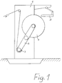
- FIG. 1 shows a schematic illustration of a roll changer with a device according to the invention for preparing a printing material web roll.
- the detachment of the outer, damaged or deformed layers of the roller 4, which is generally required, is carried out by hand or by means of a device specially designed for this purpose, but this is not of importance for the present invention and is therefore not considered further here.
- "preparation” is understood only to mean cutting a leading edge of the web, creating a predetermined breaking line or tear line, and applying a holding adhesive and a connecting adhesive.
- the adhesive is applied so that the beginning of the web can be glued to the outermost layer of the web roll to be wound.
- the connecting adhesive is applied in such a way that it is possible to glue the printing material web to be replaced to the new printing material web with undiminished processing.
- a roll 3 of web-shaped printing material which is being developed and a new roll 4 of web-shaped printing material which is provided as a replacement roll are clamped onto a roll changer frame 1 with swivel frame 2 which is known per se.
- a device designated overall by reference number 5, which is described in more detail below, is attached to the roll change frame 1 in such a way that it can be brought up to the new roll 4 in preparation for this. However, it can also be designed as a device which can be moved freely with respect to the roll change frame 1. To carry out the roll preparation, the movable device 5 is brought into a position which is fixed in relation to the roll change frame 1.
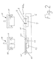
- FIG. 2 shows a schematic illustration of a first device according to the invention for preparing a printing material web roll 4, from which a web 41 is to be unwound, in a first way according to the invention.
- the position of the web 41 is shown as follows: during the cutting and perforating process, it has the position shown in broken lines and identified by the reference number 41a, while during the application of the adhesive it has the position shown by the solid line and indicated by the reference number 41 .
- a base plate 6 of the device 5 has an upper surface 61 on which the web 41 of the new roll 4 to be prepared rests during the adhesive tip preparation process.
- a knife bar 7 is embedded in the surface 61 transversely to the unwinding direction of the new roll 4 so that only the cutting edges of a cutting knife 8 and a perforating knife 9 protrude from the surface 61.
- the cutting knife 8 and the perforating knife 9 are arranged on the cutter bar 7 at a distance a (see FIG. 3) from one another and parallel to one another.
- a pressing device 10 is arranged above the cutter bar 7 and both on the cutter bar 7 and movable along it, in a manner known per se and therefore not shown in detail.
- the pressing device 10 has an elastic roller 11, for example a rubber roller.
- the base plate 6 has an adhesive application plate 12 which is flush with the surface 61 and has an upper surface 121.
- the surface 121 is provided with a holding adhesive groove 13, the width of which is preferably smaller, but in no case greater than the distance dimension a.
- a pressure roller 14 can be lowered onto the holding adhesive groove 13 and can be moved along it.
- the width of the pressure roller 14 is smaller than the width of the holding adhesive groove 13.
- a connecting adhesive application roller 15 is also arranged so that it can be lowered onto it and moved along it so that between the a small space remains between the two rollers 14 and 15.
- connection adhesive application roller 15 can be, for example, an adhesive tape dispenser for double-sided adhesive tape or an application roller for liquid adhesive.
- both rollers are mounted in a common, lowerable frame 16 in order to make the axial distance between the two rollers as small as possible.
- the section of the surface 121 adjoining the holding adhesive groove 13 from the cutter bar 7 and the section of the surface 61 adjoining it are provided with an anti-adhesive layer 17.
- the cutter bar 7 and the adhesive application plate 12 can be formed as a single element.
- the elastic roller 11, the pressure roller 14 and the connecting adhesive application roller 15 can also be mounted in a common, movably or movably arranged holding element, so as to cut the web edge 42, perforate and apply the adhesive in a single operation and without being able to partially wind up the web 41.
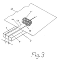
- FIG. 3 shows a greatly simplified perspective illustration of the knife bar 7 with the cutting knife 8 and the perforating knife 9 as well as the rubber roller 11 of the device 5 shown in FIG. 2.
- the knife bar 7 and the rubber roller 11 can also be modified from the embodiment described with reference to FIG be arranged at an angle of less than 90 ° to the unwinding direction of the web 41. Instead of a straight cut edge, the start of the web is then given an oblique cut edge.
- the pressing device 10 can have a bar made of elastic material, for example made of rubber, which presses the printing material over the entire web width onto the two knives and thus produces the cut and the perforation.
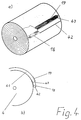
- FIG. 4 shows, in a simplified perspective illustration (FIG. 4 a) and in a partial side view (FIG. 4 b), a printing material web roll 4 prepared in a first way according to the invention by means of a device of the first exemplary embodiment , the connection adhesive 19 required for gluing the old web to the new web and the perforation 43 which enables the new web to be torn off safely and free of damage after it has been glued.
- the preparation of the adhesive tip of the new roll 4 with the device 5 shown in FIGS. 2 and 3 is carried out essentially in the manner described below.
- the web 41 is unwound from the roll 4 and placed on the base plate 6 so that the web 41 completely covers the adhesive application plate 12 and the base plate 6.
- the pressing device 10 located at one end of the cutter bar 7 is lowered onto the cutter bar 7 to such an extent that the rubber roller 11 presses on the cutters 8 and 9.
- the web 41 is provided with a straight cutting edge 42 and a perforation 43 running parallel to the cutting edge 42 in a single operation by the pressure of the rubber roller 11.
- the web 41 is wound onto the roll 4 by a predetermined web length. This length is dimensioned such that the cutting edge 42 comes to rest on the edge of the holding adhesive groove 13 facing the cutter bar 7. At the same time, the perforation 43 comes to lie on the surface 121 in the area corresponding to the space between the two rollers 14 and 15.
- both adhesives are applied in a single operation: Pressure of the roll 14, a holding adhesive 18 located in the holding adhesive groove 13, is applied to the underside of a section 44 of the web 41 delimited by the cutting edge 42 and the perforation 43, and on the other hand, a connecting adhesive 19 is applied to the upper side of the section by the roll 15 44 applied from the area of the web 41 adjoining the perforation 43.
- the holding adhesive and the connecting adhesive can be either of the same or of a different dosage form.
- both adhesive tapes and spreadable or sprayable adhesives can be used.
- the adhesiveness of the two adhesives can be different. However, both adhesives must have the property of bilateral adhesion.
- the new printing material web roll in the roll changer is driven with a belt engaging on the circumference of the roll, it is expedient not to provide the area of the beginning of the web in which the belt touches the roll with the connecting adhesive 19. If the drive is made with several belts, several areas must be left out accordingly.
- a modified design of the perforation in the cut-out area or in the cut-out areas is advantageous for belt drives. If you keep the continuous perforation shown in Figure 4 and leave it alone with an interrupted adhesive line, then when the perforation is torn, there is usually an uneven transfer of force to the tearable position of the printing material and thus uncontrollable tears in the area of the belt position or Belt positions. Triangular, round and, preferably, trapezoidal perforation courses have proven to be an advantageous design of the perforation in the belt area.
- the web 41 is completely wound onto the printing material web roll 4.
- the non-stick layer 17 prevents the adhesive applied to the underside of the web 41 from sticking to the surface 121 of the adhesive application plate 12 or to the surface 61 of the base plate 6.
- winding the adhesive beginning of the web 41 of the web 41 means known per se, such as, for example (not shown) non-stick pressure rollers, ensure that the web 41 is wound without air entrapment and that the web start is secure and over the full width of the web on the roll 4 is glued.
- the cutter bar 7 and the associated pressing device 10 on the one hand and the adhesive application plate 12 and the associated connecting adhesive application roller 15 on the other hand can each be designed to be pivotable.
- one or the other pair of devices is pivoted into a position corresponding, for example, to the position of the knife bar.
- the cutter bar 7 and the adhesive application plate 12 can be combined to form a single element, the perforating knife 9 and possibly also the cutting blade 8 being designed to be countersunk in the cutter bar 7 in order to ensure the dimensioning and guidance of the Not having to determine pressure roller 14 so precisely that contact of pressure roller 14 with one or the other of the two knives 8 and 9 is reliably prevented.
- This modification of the exemplary embodiment also includes Combine pressing device 10 and the connecting adhesive application roller 15 to form a device which can be moved together over the printing material web.
- the pressing device 10 and the connecting adhesive application roller 15 are axially aligned with one another, whether they are arranged axially parallel and one behind the other, whether they are arranged axially parallel but overlapping to one another or whether they are arranged in another suitable manner. Likewise, it is immaterial whether the pressing device 10 leads or lags the non-axial alignment during the movement from one web edge to the other web edge of the connecting adhesive application roller 15, whether - seen in slow motion - first cut and then adhesive is applied or vice versa. As a result, even in this development of the device according to the invention, the essential advantage of not having to first move the pressing device 10 and the connecting adhesive application roller 15 into an initial position is retained.
- FIG. 5 shows the elements of a device for preparing a printing material web roll in a second embodiment according to the invention, insofar as this device differs from the device according to FIG. 2.
- features which are shown and described and which correspond to the corresponding features of the device according to FIG. 2 are provided with the same reference symbols.
- the cutter bar 7 has, instead of the perforating knife 9, a pair of perforating knives formed from two similar and offset-arranged knives, designated by the reference numerals 91 and 92.
- the cutter bar 7 is composed of a first cutter holder 71 which is fixedly arranged in the base plate 6 (see FIG. 2) and a second cutter holder 72 which is adjustable relative to the cutter holder 71. While the first knife holder 71 has the first knife 91 in addition to the cutting knife 8, the second knife holder 72 has the second knife 92.
- the first knife 91 is correspondingly arranged at a distance a from the cutting knife 8 and parallel to it.
- the second knife 92 is arranged at a distance b (see FIG. 8) from the first knife 91 and parallel to it. Due to the adjustability of the second knife holder 72 relative to the first knife holder 71, the distance b between the two knives 91 and 92 can be set so that the desired perforation pattern of the perforation 43a, which is formed by the partial perforations 431 and 432, can be obtained.
- FIG. 6 shows a simplified perspective illustration of a printing material web roll prepared by means of a device of the second exemplary embodiment in a second way according to the invention.
- the adhesive 18 holding the start of the roll on the roll, the connecting adhesive 19 required for adhering the old web to the new web, and the perforation 43a which enables the new web to be torn off safely and without damage after the adhesive has been applied are clearly recognizable.
- FIG. 7 shows different perforation patterns of the perforation 43a, which can be obtained with a device according to the second exemplary embodiment by a corresponding choice of the knife geometry.
- the cuts made alternately by the first knife 91 and the second knife 92, viewed in the cutting direction , next to each other (A), with a distance (B) or overlapping (C).
- FIG. 8 shows different perforation patterns of the perforation 43a, which can be obtained with a device according to the second exemplary embodiment.
- the different perforation patterns in the embodiment according to FIG. 8 are obtained with knives of the same pitch but different distance b.
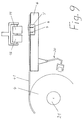
- FIG. 9 shows, in a simplified side view of the preparation device, a change which can be carried out in the two exemplary embodiments described above, according to which the holding adhesive 18 is not applied by means of the holding adhesive groove 13 and the associated pressure roller 14. Instead, the holding adhesive 18 is applied by an application device 20 to the outermost layer of the printing material web roll to be prepared.
- the size and arrangement of the surface section of the outermost layer to which the holding adhesive 18 is to be applied is to be determined in such a way that the section 44 of the beginning of the web delimited by the cutting edge 42 and the perforations 43 or 43a has this surface section after the web 41 has been wound up completely covered on roll 4.
- the pressure roller 11 and the connecting adhesive application roller 15 can be attached to separate holding and guiding elements, which can be moved separately or together, on a common holding and guiding frame, as shown in FIG. 9, or in be arranged in any other appropriate manner.
- the pressure roller 11 and the connecting adhesive application roller 15 are axially aligned with one another, whether they are arranged axially parallel and one behind the other, or whether they are axially parallel but overlapping.
- a motor 21 is disclosed in FIG.
- the motor 21 serves, in the manner described above, to partially and completely wind the web 41 onto the printing material web roll 4.
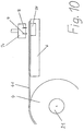
- Figure 10 shows a further development of the device shown in Figure 9, the difference between the two devices essentially consists only in that the cutting knife 8 and the perforating knife 9 are mounted in a movable or movable holder 74 and that a pressure plate 75 on which the knives 8 and 9 are pressed, is arranged in the base plate 6.
- the adhesive application can be carried out in accordance with FIG. 2 or FIG. 9.
Landscapes
- Replacement Of Web Rolls (AREA)
- Folding Of Thin Sheet-Like Materials, Special Discharging Devices, And Others (AREA)
Priority Applications (1)
| Application Number | Priority Date | Filing Date | Title |
|---|---|---|---|
| EP94115357A EP0633211B1 (de) | 1991-06-07 | 1992-05-29 | Verfahren zur Vorbereitung einer Bedruckstoffbahn für den fliegenden Rollenwechsel und eine insbesondere derart hergestellte Rolle |
Applications Claiming Priority (2)
| Application Number | Priority Date | Filing Date | Title |
|---|---|---|---|
| DE4118690A DE4118690A1 (de) | 1991-06-07 | 1991-06-07 | Verfahren und vorrichtung zur vorbereitung einer papierrolle fuer den fliegenden rollenwechsel |
| DE4118690 | 1991-06-07 |
Related Child Applications (1)
| Application Number | Title | Priority Date | Filing Date |
|---|---|---|---|
| EP94115357.9 Division-Into | 1992-05-29 |
Publications (2)
| Publication Number | Publication Date |
|---|---|
| EP0517101A1 EP0517101A1 (de) | 1992-12-09 |
| EP0517101B1 true EP0517101B1 (de) | 1995-06-28 |
Family
ID=6433378
Family Applications (2)
| Application Number | Title | Priority Date | Filing Date |
|---|---|---|---|
| EP94115357A Expired - Lifetime EP0633211B1 (de) | 1991-06-07 | 1992-05-29 | Verfahren zur Vorbereitung einer Bedruckstoffbahn für den fliegenden Rollenwechsel und eine insbesondere derart hergestellte Rolle |
| EP92109010A Expired - Lifetime EP0517101B1 (de) | 1991-06-07 | 1992-05-29 | Verfahren und Vorrichtung zur Vorbereitung einer Bedruckstoffbahnrolle für den fliegenden Rollenwechsel |
Family Applications Before (1)
| Application Number | Title | Priority Date | Filing Date |
|---|---|---|---|
| EP94115357A Expired - Lifetime EP0633211B1 (de) | 1991-06-07 | 1992-05-29 | Verfahren zur Vorbereitung einer Bedruckstoffbahn für den fliegenden Rollenwechsel und eine insbesondere derart hergestellte Rolle |
Country Status (5)
| Country | Link |
|---|---|
| US (1) | US5318656A (ja) |
| EP (2) | EP0633211B1 (ja) |
| JP (1) | JP3300031B2 (ja) |
| CA (1) | CA2069247C (ja) |
| DE (3) | DE4118690A1 (ja) |
Families Citing this family (23)
| Publication number | Priority date | Publication date | Assignee | Title |
|---|---|---|---|---|
| DE4210328A1 (de) * | 1992-03-30 | 1993-10-07 | Koenig & Bauer Ag | Klebestellenanordnung für eine neue Vorratsrolle zum automatischen Verbinden von Rollenbahnen durch Klebemittel |
| DE9213430U1 (de) * | 1992-10-06 | 1993-01-07 | Herlitz Ag, 1000 Berlin | Verpackung für Papier in Rollenform |
| NL9300707A (nl) * | 1993-04-26 | 1994-11-16 | Knp Papier Bv | Werkwijze voor het lassen van een papierbaan en een kleefstrook ten gebruike bij deze werkwijze. |
| US5431767A (en) * | 1993-08-27 | 1995-07-11 | Minnesota Mining And Manufacturing Company | Apparatus for applying adhesive tape |
| US5524844A (en) * | 1993-10-29 | 1996-06-11 | Enkel Corporation | Apparatus for preparing a leading edge of web material |
| JP3553960B2 (ja) * | 1994-04-26 | 2004-08-11 | ミネソタ マイニング アンド マニュファクチャリング カンパニー | 添えつぎテープ、添えつぎ方法及び添えつぎテープを使用した添えつぎ |
| USRE38356E1 (en) * | 1994-04-26 | 2003-12-23 | 3M Innovative Properties Company | Splicing method and splice using the splicing tape |
| DE4424888C2 (de) | 1994-07-14 | 1996-10-31 | Koenig & Bauer Albert Ag | Anordnung zum Befestigen eines Anfanges einer Papierbahn einer Vorratspapierbahnrolle |
| DE4424902C2 (de) * | 1994-07-14 | 1997-02-13 | Koenig & Bauer Albert Ag | Klebemittelanordnung |
| DE4424657C1 (de) | 1994-07-14 | 1996-02-08 | Koenig & Bauer Albert Ag | Material für das Befestigen eines Anfanges einer Vorratspapierbahnrolle |
| CA2194185A1 (en) * | 1994-07-20 | 1996-02-01 | Steven J. Rossini | Apparatus for applying adhesive tape |
| US6951676B2 (en) | 2000-09-25 | 2005-10-04 | 3M Innovative Properties Company | Butt splicing tapes and butt splicing methods |
| DE10058458B4 (de) * | 2000-11-24 | 2005-12-08 | Koenig & Bauer Ag | Vorrichtung zum Verbinden zweier Materialbahnen |
| US6808581B2 (en) * | 2001-06-15 | 2004-10-26 | 3M Innovative Properties Company | Method and apparatus for automatically applying a flying splicing tape to a roll of sheet material |
| DE10139563B4 (de) * | 2001-08-10 | 2006-12-14 | Man Roland Druckmaschinen Ag | Vorrichtung und Verfahren zur Vorbereitung einer Vorratspapierbahnrolle für den fliegenden Rollenwechsel |
| US6814123B2 (en) * | 2001-12-21 | 2004-11-09 | 3M Innovative Properties Company | Method and apparatus for applying a splicing tape to a roll of sheet material |
| US6899933B2 (en) * | 2002-09-09 | 2005-05-31 | Permacel | Splicing tape with separating portions |
| ES2261574T3 (es) * | 2002-10-14 | 2006-11-16 | Metso Paper Ag | Procedimiento y dispositivo para la preparacion de una bobina de papel para el cambio automatico de la bobina. |
| US7476429B2 (en) * | 2003-11-03 | 2009-01-13 | Permacel | Bridge label for splicing tape |
| WO2006039940A1 (en) * | 2004-10-13 | 2006-04-20 | Nitto Europe N.V. | Adhesive tape and method for changing a reel |
| AT503396B1 (de) * | 2006-03-16 | 2008-05-15 | Friedrich Kerber | Verfahren zur herstellung einer rutschhemmenden beschichtung |
| DE102013017224A1 (de) * | 2013-10-17 | 2015-04-23 | Manroland Web Systems Gmbh | Verfahren und Vorrichtung zum Bearbeiten einer Bedruckstoffbahn |
| DE102015113496A1 (de) * | 2015-08-14 | 2017-02-16 | Krones Aktiengesellschaft | Vorratsrolle mit mindestens einer Soll-Bruchstelle und Verfahren zum Umgang mit einer solchen Vorratsrolle |
Family Cites Families (20)
| Publication number | Priority date | Publication date | Assignee | Title |
|---|---|---|---|---|
| US1975348A (en) * | 1931-08-24 | 1934-10-02 | Allan J Cline | Method and apparatus for making high speed pasters |
| GB452328A (en) * | 1935-05-14 | 1936-08-20 | Henry Vincent James | Improvements in or relating to web-renewing devices for printing machines |
| US2104774A (en) * | 1935-06-12 | 1938-01-11 | David J Scott | Paper roll and method of splicing to expiring web |
| US2377971A (en) * | 1943-12-15 | 1945-06-12 | Wood Newspaper Mach Corp | Means for use in splicing webs |
| US2596189A (en) * | 1946-08-19 | 1952-05-13 | Hoe & Co R | Method for replacing web rolls in printing machines |
| US2812145A (en) * | 1955-06-02 | 1957-11-05 | Edward J Meloche | Method of and means for splicing webs |
| US3532573A (en) * | 1966-03-08 | 1970-10-06 | Scott Paper Co | Method and apparatus for winding continuous webs and adhesively securing the tail end |
| US3547739A (en) * | 1969-05-15 | 1970-12-15 | Harvey N Beute | Perforated tape |
| US3741079A (en) * | 1969-10-16 | 1973-06-26 | Masson Scott Thrissell Eng Ltd | Web splicing methods |
| US4080231A (en) * | 1972-12-16 | 1978-03-21 | Rengo Co., Ltd. | Paper roll splicing method |
| DE2337663C2 (de) * | 1973-07-25 | 1986-12-11 | M.A.N.- Roland Druckmaschinen AG, 6050 Offenbach | Vorrichtung zum Vorbereiten von Wickelrollen aus Bahnmaterial für das Abwickeln für den Druck |
| US3960272A (en) * | 1974-06-03 | 1976-06-01 | Crown Zellerbach Corporation | Roll product with manually graspable tail end and manufacture thereof |
| US4284463A (en) * | 1979-03-16 | 1981-08-18 | Butler Greenwich Inc. | Web preparation apparatus |
| US4299642A (en) * | 1980-08-01 | 1981-11-10 | Nelson R. Stauffer | Tail sealing apparatus |
| JPS602553A (ja) * | 1983-06-20 | 1985-01-08 | Dainippon Printing Co Ltd | 巻取紙ほぐれ止めテ−プ処理方法および装置 |
| JP2545557B2 (ja) * | 1987-11-12 | 1996-10-23 | ハマダ印刷機械株式会社 | 巻取紙の端末処理方法およびその装置 |
| US4984750A (en) * | 1988-07-01 | 1991-01-15 | Tokyo Automatic Machinery Works Ltd. | Method and apparatus for replacing web-like material in a web-like material supplying device |
| US4905924A (en) * | 1989-07-10 | 1990-03-06 | Enkel Corporation | Web splicing tape |
| EP0418527A3 (en) * | 1989-09-19 | 1992-01-22 | Man Roland Druckmaschinen Ag | Method to prepare a roll of breadths of print cloth for an automatic reel changer |
| US5030311A (en) * | 1989-10-02 | 1991-07-09 | Eastman Kodak Company | Method and apparatus for taping lead and tail ends of web during winding onto a core |
-
1991
- 1991-06-07 DE DE4118690A patent/DE4118690A1/de active Granted
-
1992
- 1992-05-13 US US07/882,599 patent/US5318656A/en not_active Expired - Lifetime
- 1992-05-22 CA CA002069247A patent/CA2069247C/en not_active Expired - Lifetime
- 1992-05-29 DE DE59202670T patent/DE59202670D1/de not_active Expired - Lifetime
- 1992-05-29 EP EP94115357A patent/EP0633211B1/de not_active Expired - Lifetime
- 1992-05-29 EP EP92109010A patent/EP0517101B1/de not_active Expired - Lifetime
- 1992-05-29 DE DE59208960T patent/DE59208960D1/de not_active Expired - Fee Related
- 1992-06-04 JP JP14422392A patent/JP3300031B2/ja not_active Expired - Fee Related
Also Published As
| Publication number | Publication date |
|---|---|
| CA2069247A1 (en) | 1992-12-08 |
| EP0633211A3 (de) | 1995-03-01 |
| EP0517101A1 (de) | 1992-12-09 |
| US5318656A (en) | 1994-06-07 |
| JP3300031B2 (ja) | 2002-07-08 |
| DE4118690A1 (de) | 1992-12-10 |
| CA2069247C (en) | 1998-06-23 |
| DE59202670D1 (de) | 1995-08-03 |
| JPH05155482A (ja) | 1993-06-22 |
| DE4118690C2 (ja) | 1993-05-19 |
| DE59208960D1 (de) | 1997-11-13 |
| EP0633211B1 (de) | 1997-10-08 |
| EP0633211A2 (de) | 1995-01-11 |
Similar Documents
| Publication | Publication Date | Title |
|---|---|---|
| EP0517101B1 (de) | Verfahren und Vorrichtung zur Vorbereitung einer Bedruckstoffbahnrolle für den fliegenden Rollenwechsel | |
| EP0450312B1 (de) | Verfahren zum Verbinden des Bahnanfanges eines Wickels an einer Splice-Stelle mit dem Bahnende einer von einem anderen Wickel ablaufenden Bahn | |
| EP0566880B1 (de) | Anordnung zum Verbinden aufeinanderfolgender, zu Rollen gewickelter Papierbahnen | |
| DE3521907C2 (de) | Vorrichtung zum Miteinanderverbinden eines Endes einer ersten Bahn und eines Anfangs einer zweiten Bahn | |
| DE4033900C2 (de) | Splice-Stelle am Bahnanfang eines Wickels zum Verbinden des Bahnanfangs mit dem Bahnende eines anderen Wickels | |
| EP0418527A2 (de) | Verfahren zum Vorbereiten einer Rolle bahnförmigen Bedruckstoffs für automatische Rollenwechsler | |
| EP0060450B1 (de) | Vorrichtung zum Verbinden des hinteren Endes einer von einer auslaufenden Rolle abgezogenen Bahn mit dem vorderen Ende einer von einer Ersatzrolle abgezogenen Bahn | |
| EP0108761B1 (de) | Verfahren und vorrichtung zum perforieren, stanzen oder rillen von papier und karton in rotationsdruckmaschinen | |
| DE4000745C2 (ja) | ||
| DE69816094T2 (de) | Vorrichtung zum rückfaltenfreien verbinden von bahnen mit elektrostatischer vorrichtung zur übergabe der bahn | |
| EP0546457B1 (de) | Klebevorrichtung | |
| EP0683122B1 (de) | Klebemittel zum Verbinden von auf angetriebenen Rollen gewickelten Materialbahnen | |
| EP0071229B1 (de) | Verfahren zur kontinuierlichen Herstellung von Faltschachteln sowie Vorrichtung hierzu | |
| DE69615639T2 (de) | Herstellung von Kennzeichenschildern für Fahrzeuge | |
| DE3834334C2 (de) | Bearbeitungseinrichtung zur Vorbereitung des Bahnendes einer Rolle einer Warenbahn | |
| DE10139563B4 (de) | Vorrichtung und Verfahren zur Vorbereitung einer Vorratspapierbahnrolle für den fliegenden Rollenwechsel | |
| DE19744103C2 (de) | Vorrichtung zum Schneiden, Ankleben und Kennzeichnen eines band- oder streifenförmigen Materials, insbesondere aus Papier | |
| EP0982228A1 (de) | Verfahren und Vorrichtung zum Verpacken von Materialbahnrollen | |
| DE10351877B4 (de) | Schneidvorrichtung zum Abtrennen von Etiketten, Verfahren zum Abtrennen von Etiketten und Druckvorrichtung | |
| DE1173784B (de) | Mit Schneidwalzen arbeitende Vorrichtung zur kontinuierlichen Herstellung von Haftetiketten | |
| EP0193626A1 (de) | Vorrichtung zum Aufbringen eines Aufreissbandes oder dergleichen auf Wellpappen-, Pappen-, Papierbahnen o. dgl. | |
| EP0574869A2 (de) | Verfahren und Anordnung zur Herstellung einer Klebespitze für zu verspleissende Papierrollen | |
| EP1438247B1 (de) | Klebeband für fliegenden rollenwechsel | |
| DE3027487C2 (de) | Verfahren und Vorrichtung zur Herstellung von selbstklebenden Klebebandstreifen | |
| EP1529011A2 (de) | Verfahren, system und vorrichtung zur vorbereitung einer wickelrolle zum fliegenden rollenwechsel, zum erfassen einer warenbahn und zum aufbringen eines doppelseitigen klebebandes auf eine oberfl che |
Legal Events
| Date | Code | Title | Description |
|---|---|---|---|
| PUAI | Public reference made under article 153(3) epc to a published international application that has entered the european phase |
Free format text: ORIGINAL CODE: 0009012 |
|
| AK | Designated contracting states |
Kind code of ref document: A1 Designated state(s): CH DE FR GB IT LI SE |
|
| 17P | Request for examination filed |
Effective date: 19921212 |
|
| 17Q | First examination report despatched |
Effective date: 19940729 |
|
| GRAA | (expected) grant |
Free format text: ORIGINAL CODE: 0009210 |
|
| ITF | It: translation for a ep patent filed | ||
| AK | Designated contracting states |
Kind code of ref document: B1 Designated state(s): CH DE FR GB IT LI SE |
|
| XX | Miscellaneous (additional remarks) |
Free format text: TEILANMELDUNG 94115357.9 EINGEREICHT AM 29/05/92. |
|
| REF | Corresponds to: |
Ref document number: 59202670 Country of ref document: DE Date of ref document: 19950803 |
|
| ET | Fr: translation filed | ||
| GBT | Gb: translation of ep patent filed (gb section 77(6)(a)/1977) |
Effective date: 19951005 |
|
| PLBE | No opposition filed within time limit |
Free format text: ORIGINAL CODE: 0009261 |
|
| STAA | Information on the status of an ep patent application or granted ep patent |
Free format text: STATUS: NO OPPOSITION FILED WITHIN TIME LIMIT |
|
| 26N | No opposition filed | ||
| REG | Reference to a national code |
Ref country code: GB Ref legal event code: IF02 |
|
| REG | Reference to a national code |
Ref country code: CH Ref legal event code: PFA Owner name: M.A.N.-ROLAND DRUCKMASCHINEN AKTIENGESELLSCHAFT Free format text: M.A.N.-ROLAND DRUCKMASCHINEN AKTIENGESELLSCHAFT#MUEHLHEIMERSTRASSE 341#D-63075 OFFENBACH A.M. (DE) -TRANSFER TO- M.A.N.-ROLAND DRUCKMASCHINEN AKTIENGESELLSCHAFT#MUEHLHEIMERSTRASSE 341#D-63075 OFFENBACH A.M. (DE) |
|
| REG | Reference to a national code |
Ref country code: CH Ref legal event code: PFA Owner name: MANROLAND AG Free format text: M.A.N.-ROLAND DRUCKMASCHINEN AKTIENGESELLSCHAFT#MUEHLHEIMERSTRASSE 341#D-63075 OFFENBACH A.M. (DE) -TRANSFER TO- MANROLAND AG#MUEHLHEIMER STRA?E 341#63075 OFFENBACH (DE) |
|
| PGFP | Annual fee paid to national office [announced via postgrant information from national office to epo] |
Ref country code: CH Payment date: 20110524 Year of fee payment: 20 Ref country code: FR Payment date: 20110607 Year of fee payment: 20 Ref country code: SE Payment date: 20110513 Year of fee payment: 20 |
|
| PGFP | Annual fee paid to national office [announced via postgrant information from national office to epo] |
Ref country code: GB Payment date: 20110520 Year of fee payment: 20 |
|
| PGFP | Annual fee paid to national office [announced via postgrant information from national office to epo] |
Ref country code: IT Payment date: 20110527 Year of fee payment: 20 Ref country code: DE Payment date: 20110520 Year of fee payment: 20 |
|
| REG | Reference to a national code |
Ref country code: DE Ref legal event code: R071 Ref document number: 59202670 Country of ref document: DE |
|
| REG | Reference to a national code |
Ref country code: DE Ref legal event code: R071 Ref document number: 59202670 Country of ref document: DE |
|
| REG | Reference to a national code |
Ref country code: CH Ref legal event code: PL |
|
| REG | Reference to a national code |
Ref country code: GB Ref legal event code: PE20 Expiry date: 20120528 |
|
| REG | Reference to a national code |
Ref country code: SE Ref legal event code: EUG |
|
| PG25 | Lapsed in a contracting state [announced via postgrant information from national office to epo] |
Ref country code: DE Free format text: LAPSE BECAUSE OF EXPIRATION OF PROTECTION Effective date: 20120530 |
|
| PG25 | Lapsed in a contracting state [announced via postgrant information from national office to epo] |
Ref country code: GB Free format text: LAPSE BECAUSE OF EXPIRATION OF PROTECTION Effective date: 20120528 |