EP0193626A1 - Vorrichtung zum Aufbringen eines Aufreissbandes oder dergleichen auf Wellpappen-, Pappen-, Papierbahnen o. dgl. - Google Patents
Vorrichtung zum Aufbringen eines Aufreissbandes oder dergleichen auf Wellpappen-, Pappen-, Papierbahnen o. dgl. Download PDFInfo
- Publication number
- EP0193626A1 EP0193626A1 EP85102379A EP85102379A EP0193626A1 EP 0193626 A1 EP0193626 A1 EP 0193626A1 EP 85102379 A EP85102379 A EP 85102379A EP 85102379 A EP85102379 A EP 85102379A EP 0193626 A1 EP0193626 A1 EP 0193626A1
- Authority
- EP
- European Patent Office
- Prior art keywords
- tape
- pressure roller
- vacuum
- web
- cutting device
- Prior art date
- Legal status (The legal status is an assumption and is not a legal conclusion. Google has not performed a legal analysis and makes no representation as to the accuracy of the status listed.)
- Withdrawn
Links
- 239000000123 paper Substances 0.000 claims abstract description 4
- 239000000853 adhesive Substances 0.000 description 3
- 238000003825 pressing Methods 0.000 description 2
- 238000004026 adhesive bonding Methods 0.000 description 1
- 239000000463 material Substances 0.000 description 1
- 238000000034 method Methods 0.000 description 1
- 230000002093 peripheral effect Effects 0.000 description 1
- 230000001105 regulatory effect Effects 0.000 description 1
Images
Classifications
-
- B—PERFORMING OPERATIONS; TRANSPORTING
- B65—CONVEYING; PACKING; STORING; HANDLING THIN OR FILAMENTARY MATERIAL
- B65H—HANDLING THIN OR FILAMENTARY MATERIAL, e.g. SHEETS, WEBS, CABLES
- B65H35/00—Delivering articles from cutting or line-perforating machines; Article or web delivery apparatus incorporating cutting or line-perforating devices, e.g. adhesive tape dispensers
- B65H35/0006—Article or web delivery apparatus incorporating cutting or line-perforating devices
- B65H35/002—Hand-held or table apparatus
- B65H35/0026—Hand-held or table apparatus for delivering pressure-sensitive adhesive tape
- B65H35/0033—Hand-held or table apparatus for delivering pressure-sensitive adhesive tape and affixing it to a surface
Definitions
- the invention relates to a device for applying a tear tape or the like to corrugated cardboard, cardboard, paper webs or the like: with a frame in which a pressure roller is rotatably and slidably mounted transversely to the direction of travel of the web, which Tape is fed from a supply roll and which presses the tape against the web, and a cutting device for cutting the tape in the event of a format change or the like.
- the tear tape which is usually made of plastic material, is self-adhesive on one side. It is unwound from a supply roll and pulled off the corrugated cardboard web from the supply roll and pressed against the corrugated cardboard web with the aid of the pressure roller. It is understood that the position of the tear tape / seen in the transverse direction of the corrugated cardboard is different - depending on the format used. When changing the format, the tear tape is cut and the pressure roller is brought into the new desired position. A disadvantage of this process is that the tear tape must always be re-threaded through a guide roller to the pressure roller. This is not only time-consuming, but also relatively cumbersome, since there is little space in the area of the creasing and cutting machine of a corrugated cardboard system.
- the invention has for its object to provide a device for applying tear tape on corrugated cardboard, cardboard, paper webs or the like, which permits automatic or semi-automatic adjustment in the event of a format change and makes manipulations with the tear tape unnecessary in such an adjustment.
- the cutting device is arranged near the pressure roller, the pressure roller is assigned a holding device which either holds or releases the tear tape and a control device controls the cutting device and the holding device in such a way that in the event of a format change the cutting device cuts the tape approximately simultaneously and the holding device detects the tape.
- the position of the pressure roller is predetermined and determined by the position of the tear tape in relation to the format used.
- the pressure roller or the other associated parts can be moved laterally so that an adjustment can be made automatically or semi-automatically when the format is changed. This can be done with the help of a suitable control device, e.g. is monitored by the control of a corrugated cardboard system.
- these parts can also be moved to adapt to the web edge position.
- the cutting and creasing tools are regulated as a function of the web edge position, which is detected with the aid of suitable sensors. Accordingly, the device for applying the tear tape of the web edge layer can be traced.
- the cutting device cuts the tear tape. This can be done with the help of a suitable translationally operated knife or a knife roller happen.
- the holding device grips the tape and temporarily holds it. Then an adjustment is made with regard to the new format.
- the holding device releases the tape so that it can be applied against the web in the usual way using the pressure roller.
- the cutting device is arranged behind or in the region of the holding device, viewed in the direction of travel of the belt. This can ensure that when the cutting device is actuated, the band is in the holding device and is not pulled out in an undesirable manner.
- the holding device has a lower surface which can be connected to a vacuum source and along which the strip is guided.
- the other solution is to hold the tape mechanically. The latter is discussed in more detail below.
- one embodiment of the invention provides that the pressure roller has vacuum openings on its circumference, which can be connected via radial bores to a vacuum channel in the shaft connected to the vacuum source for the pressure roller. If the tape is to be held, the vacuum channel is connected to the vacuum source, and a negative pressure is generated in the holes on the circumference of the pressure roller, which now holds it in the area of the pressure roller being wrapped around it.
- the cutting device ensures that the tape which has already been stuck on no longer pulls the tear tape off the supply roll by cutting through the tear tape.
- it is preferably arranged or mounted in such a way that it can be raised by a small amount relative to the web. Pressurization with a relatively soft spring may also be sufficient. In the event of a hold, the pressure roller is raised against the spring by a small amount and thereby disengages from the web.
- the cutting device is arranged behind the pressure roller and only those radial bores which are connected to the vacuum channel are connected to the vacuum channel Beginning of the wrapping area facing the pressure roller.
- a vacuum box which can be connected to the vacuum source is arranged in front of the pressure roller, the lower side of which serves as a guiding surface for the tape and is provided with openings.
- the cutting device which is designed, for example, as a cutting roller, can be arranged in the vacuum box.
- the vacuum box can be adjusted in the direction of the web by a small amount, in order to temporarily press the tear tape onto the web in the event of the tape being reapplied, so that the self-adhesive tear tape takes it along.
- the surface that can be connected to vacuum can optionally be connected to a compressed air source. With a small pulse of compressed air, the tape can be released from the vacuum surface and pressed against the web to facilitate the start of the application of the tear tape after a format change.
- Another embodiment of the invention provides that at least two pressure rollers are rotatably mounted on an arm of a lever, which in turn is rotatably mounted about an axis of rotation, and between the pressure rollers on Lever the retainer is attached. Only one of the rollers is active as a pressure roller, while the others are on hold.
- the holding device holds the tear tape between the rolls after it has been cut.
- the lever is set in rotation and the next pressure roller takes on the function of pressing on the tear tape applied to the new format.
- the holding device can in turn have a surface that can be connected to the vacuum source. However, it can also have gripping jaws that can be adjusted relative to one another, between which, in the open position, the tape is passed unhindered.
- a corrugated cardboard web 10 is advanced in the direction of arrow 11.
- the device 12 is either in front of or behind a cutting and creasing machine for the corrugated cardboard web 10.
- the device 12 has a holder 14 which, which is not shown is displaceable transversely to the running direction 11 of the corrugated cardboard web 10 and can be adjusted with the aid of a pneumatic drive or the like. On the one hand, this is done to enable the web edge to be traced. Furthermore, the position of the device 12 must be changed in the event of a format change so that the tear strip 13 can be applied at a different location (viewed in the transverse direction).
- the holder 14 stores two supply rolls 15, 16. In the arrangement shown in FIG. 1, the band 13 is pulled off the supply roll 16 and deflected via the rolls 17, 18, 19 and 20. The rollers 18 to 20 are arranged so that a loop is formed.
- the deflection roller 19 is biased by a spring 21.
- the loop or spring 21 serve as a buffer to compensate for tension in the tear tape 13.
- a pressure roller 23 is rotatably mounted on an arm 22 of the holder 14. It serves to press the band 13 against the corrugated cardboard web 10.
- the arm 22 can be biased against the corrugated cardboard web 10 by means of a spring.
- a guide roller 24 is mounted at the articulation point of the arm 22. All of the rolls mentioned are freely rotating, since the tear-off tape 13 is pulled off the roll 16 via the corrugated cardboard web 10.
- two splice rollers 25, 26 are arranged, the latter being adjustable with the aid of an adjusting cylinder 27.
- the roller 26 is pressed against the other roller 25 with the aid of the adjusting cylinder 27. This connects the two bands in this area.
- the splicing mentioned is particularly simple because the tear tape 13 is self-adhesive on one side.
- a separating knife 28 is arranged which can be actuated by an adjusting cylinder 29 in order to sever the tear tape 23.
- the pressure roller 23b rotates on a hub 30 which is firmly seated on the shaft or axis 31.
- the latter has a radial bore 32 which is constantly connected to a segment-like channel 33 in the hub 30.
- the roller 23a has a plurality of radial bores 34 which open out on the peripheral surface.
- the radial bore 31 in the axis is connected to an axial bore 35 which can be connected to a vacuum source, not shown.
- the guide roller 24a has a circumferential groove 36 in which the band 13 is guided.
- the knife 28 is actuated so that the band 13 on the corrugated cardboard web 10 is severed.
- the small puncture of the knife 28 in the corrugated cardboard web can easily be accepted.
- the bore 35 has been connected to a vacuum.
- the region of the circumference of the pressure roller 23a which lies opposite the channel segment 33, is placed under negative pressure.
- the tape 13 is thereby held. It is also possible to slightly raise the pressure roller 23a in order to avoid the rest of the tape 13 being carried along by the corrugated cardboard web 10 and the tape 13 still being pulled off the supply roll.
- a vacuum box 40 is arranged between the guide roller 24a and the pressure roller 23b, the lower guide surface 41, which is bent backwards at an angle, is provided with a series of openings.
- the guide surface 41 is arranged at a sufficient distance from the corrugated cardboard web 10 so that the strip 13 does not come into contact with the corrugated cardboard web 10 until the pressure roller 23b is in contact.
- the surface 41 is brought as close as possible to the corrugated cardboard web.
- a roller 42 with a knife 43 which can be driven with the aid of a motor drive (not shown) in order to cut the band 13. In the event of a format change, the knife roller 42 cuts through the belt 13.
- the vacuum box 40 is connected to the vacuum source.
- air is drawn into the box 40 in the direction of the arrows 44.
- the vacuum holds the belt 13 against the surface 41.
- the device can then be moved into a new position, as already described.
- the vacuum in box 40 is interrupted.
- a slight pressure surge can also be initiated in order to press the band 13 against the surface of the corrugated cardboard web 10.
- the box 40 can be adjusted somewhat in the direction of the corrugated cardboard web 10 in order to accomplish the first gluing.
- three pressure rollers 23c are rotatably mounted on a star-shaped holder 46.
- the attachment of the pressure rollers 23c is such that they can all be used as a pressure roller in the lower position.
- the holder 26 can be adjusted by a suitable actuator.
- Vacuum boxes 40c are fastened to the holder 46 between the pressure rollers 23c. They have a guide surface 41c.
- the guide surface 41c of a vacuum box 40c guides the belt 13 to the pressure roller 23c, as shown in the drawing. In normal operation, the vacuum boxes 40c are vented.
- the knife 28 controls the tear tape 23 between the pressure roller 23c and the vacuum box 40c.
- the corresponding vacuum box 40c is connected to the vacuum source, as indicated by the arrows 44c.
- the guide surface 41c is thus subjected to negative pressure and holds the band 13 in place.
- the star-shaped holder 46 is rotated through 120 °, so that the next pressure roller 23c takes over the function of pressing on.
- the vacuum box 40c remains connected to the vacuum source until the new pressure roller 23c has reached its position. The vacuum box 40c is then vented.
Landscapes
- Making Paper Articles (AREA)
Abstract
Vorrichtung zum Aufbringen eines Aufreißbandes oder dergleichen auf eine Wellpappen-, Pappen-, Papierbahn o.dgl. mit einem Gestell, in dem eine Anpreßrolle drehbar und quer zur Laufrichtung der Bahn verschiebbar gelagert ist, der das Band von einer Vorratsrolle zugeführt wird und die das Band gegen die Bahn andrückt, und einer Schneidvorrichtung zum Durchtrennen des Bandes bei einem Formatwechsel oder dergleichen, wobei die Schneidvorrichtung (28, 29, 42, 43) nahe der Anpreßrolle (23, 23a, 23b, 23c) angeordnet ist, der Anpreßrolle eine Festhaltevorrichtung zugeordnet ist, die das Aufreißband (13) wahlweise festhält oder freigibt und eine Steuervorrichtung die Schneidvorrichtung und die Festhaltevorrichtung steuert derart, daß im Fall des Formatwechsels annähernd gleichzeitig die Schneidvorrichtung das Band (13) durchtrennt und die Festhaltevorrichtung das Band erfaßt.
Description
- Die Erfindung bezieht sich auf eine Vorrichtung zum A.uf- bringen eines Aufreißbandes oder dergleichen auf Wellpappen-, Pappen-, Papierbahnen o. dgl: mit einem Gestell, in dem eine Anpreßrolle drehbar und quer zur Laufrichtung der Bahn verschiebbar gelagert ist, der das Band von einer Vorratsrolle zugeführt wird und die das Band gegen die Bahn andrückt, und einer Schneidvorrichtung zum Durchtrennen des Bandes bei einem Formatwechsel oder dergleichen.
- Es ist bekannt, Wellpappenbahnen vor oder hinter der Schneid- und Rilleinrichtung laufend mit einem Aufreißband zu bekleben. Das Aufreißband, das üblicherweise aus Kunststoffmaterial besteht, ist einseitig selbstklebend. Es wird von einer Vorratsrolle abgewickelt und von der Wellpappenbahn von der Vorratsrolle abgezogen und mit Hilfe der Anpreßrolle gegen die Wellpappenbahn gedrückt. Es versteht sich, daß die Position des Aufreißbandes/in Querrichtung der Wellpappenbahn gesehen,unterschiedlich ist-je nach dem gefahrenen Format. Bei einem Formatwechsel wird daher das Aufreißband durchtrennt, und die Anpreßrolle wird in die neue gewünschte Position gebracht. Nachteilig bei diesem Vorgang ist, daß das Aufreißband stets erneut über eine Führungsrolle zur Anpreßrolle hin eingefädelt werden muß. Dies ist nicht nur zeitraubend, sondern auch verhältnismäßig umständlich, da im Bereich der Rill- und Schneidmaschine einer Wellpappenanlage wenig Platz vorhanden ist.
- Der Erfindung liegt die Aufgabe zugrunde, eine Vorrichtung zum Aufbringen von Aufreißband auf wellpappen-, Pappen-, Papierbahnen oder dergleichen zu schaffen, die eine automatische oder halbautomatische Verstellung im Fall eines Formatwechsels zuläßt und Manipulationen mit dem Aufreißband bei einer derartigen Verstellung überflüssig macht.
- Diese Aufgabe wird erfindungsgemäß dadurch gelöst, daß die Schneidvorrichtung nahe der Anpreßrolle angeordnet ist, der Anpreßrolle eine Festhaltevorrichtung zugeordnet ist, die das Aufreißband wahlweise festhält oder freigibt und eine Steuervorrichtung die Schneidvorrichtung und die Festhaltevorrichtung steuert derart, daß im Fall des Formatwechsels annähernd gleichzeitig die Schneidvorrichtung das Band durchtrennt und die Festhaltevorrichtung das Band erfaßt.
- Während des normalen Betriebes ist die Lage der Anpreßrolle vorgegeben und bestimmt durch die Lage des Aufreißbandes in bezug auf das gefahrene Format. Die Anpreßrolle bzw. die anderen zugehörigen Teile, wie Steuerrolle und/oder Vorratsrolle sind jedoch seitlich verschiebbar, damit automatisch oder halbautomatisch eine Verstellung bei einem Formatwechsel vorgenommen werden kann. Dies kann mit Hilfe einer geeigneten Regelvorrichtung erfolgen,die z.B. von der Steuerung einer Wellpappenanlage überwacht wird. Eine Verschiebbarkeit dieser Teile kann jedoch auch erfolgen, um eine Anpassung an die Bahnkantenlage vorzunehmen. Bekanntlich erfolgt eine Regelung der Schneid- und Rillwerkzeuge in Abhängigkeit von der Bahnkantenlage, die mit Hilfe geeigneter Sensoren erfaßt wird. Entsprechend kann die Vorrichtung zum Aufbringen des Aufreißbandes der Bahnkantenlage nachgefahren werden.
- Im Fall eines Formatwechsels durchtrennt die Schneidvorrichtung das Aufreißband. Dies kann mit Hilfe eines geeigneten translatorisch betätigten Messers oder einer Messerwalze geschehen. Gleichzeitig oder etwas früher erfaßt die Festhaltevorrichtung das Band und hält es vorübergehend fest. Anschließend erfolgt eine Verstellung im Hinblick auf das neue Format. Haben Anpreßrolle und möglicherweise vorhandene Führungsrolle diese Position erreicht, und wird das neue Format gefahren, läßt die Festhaltevorrichtung das Band los, so daß es in üblicher Weise mit Hilfe der Anpreßrolle gegen die Bahn angelegt wird.
- Die Schneidvorrichtung ist nach einer Ausgestaltung der Erfindung in Laufrichtung des Bandes gesehen hinter oder im Bereich der Festhaltevorrichtung angeordnet. Dadurch kann sichergestellt werden, daß bei Betätigung der Schneidvorrichtung das Band sich in der Festhaltevorrichtung befindet und nicht in unerwünschter Weise herausgezogen wird.
- Für das Festhalten des Aufreißbandes in der Festhaltevorrichtung bieten sich grundsätzlich zwei konstruktive Lösungen an. Die eine besteht erfindungsgemäß darin, daß die Festhaltevorrichtung eine untere an eine Vakuumquelle anschließbare Fläche aufweist, an der das Band entlanggeführt ist. Die andere Lösung besteht darin, das Band mechanisch festzuhalten. Auf letztere wird weiter unten näher eingegangen.
- Im Zusammenhang mit dem Festhalten des Bandes mittels Vakuum sieht eine Ausgestaltung der Erfindung vor, daß die Anpreßrolle an ihrem Umfang Vakuumöffnungen aufweist, die über radiale Bohrungen mit einem an die Vakuumquelle angeschlossenen Vakuumkanal in der Welle für die Anpreßrolle in Verbindung bringbar sind. Soll das Band festgehalten werden, wird der Vakuumkanal an die Vakuumquelle angeschlossen, und in den Bohrungen am Umfang der Anpreßrolle wird ein Unterdruck erzeugt, der im Bereich der Umschlingung der Anpreßrolle vom Aufreißband dieses nunmehr festhält. Die Schneidvorrichtung sorgt dafür, daß das bereits aufgeklebte Band nicht weiter Aufreißband von der Vorratsrolle abzieht, indem sie das Aufreißband durchtrennt. Um zu verhindern, daß die Anpreßrolle durch Druck auf die Bahn weiterläuft, ist diese vorzugsweise so angeordnet bzw. gelagert, daß sie um einen kleinen Betrag gegenüber der Bahn angehoben werden kann. Unter Umständen reicht auch eine Druckbeaufschlagung durch eine relativ weiche Feder. Im Fall des Festhaltens wird die Anpreßrolle um einen kleinen Betrag entgegen der Feder angehoben und gelangt dadurch .mit der Bahn außer Eingriff.
- Im Zusammenhang mit der Anpreßrolle ist es erfindungsgemäß vorteilhaft, wenn die Schneidvorrichtung hinter der Anpreßrolle angeordnet ist und nur diejenigen radialen Bohrungen jeweils an den Vakuumkanal angeschlossen sind, die dem Anfang des Umschlingungsbereich der Anpreßrolle zugekehrt sind.
- Eine andere Möglichkeit des Festhaltens mittels Vakuum besteht erfindungsgemäß darin, daß vor der Anpreßrolle ein an die Vakuumquelle anschließbarer Vakuumkasten angeordnet ist, dessen als Führungsfläche für das Band dienende untere Seite mit Öffnungen versehen ist. In diesem Zusammenhang kann die Schneidvorrichtung, die beispielsweise als Schneidrolle ausgebildet ist, im Vakuumkasten angeordnet sein. Der Vakuumkasten kann in Richtung auf die Bahn um einen kleinen Betrag verstellbar sein, um im Fall des Wiederaufbringens des Aufreißbandes dieses vorübergehend kurzzeitig an die Bahn anzudrücken, damit diese das selbstklebende Aufreißband mitnimmt. Anstelle des mechanischen Andrucks kann gemäß einer weiteren Ausgestaltung der Erfindung vorgesehen sein, daß die an Vakuum anschließbare Fläche wahlweise mit einer Druckluftquelle verbindbar ist. Durch einen kleinen Druckluftimpuls kann das Band von der Vakuumfläche gelöst und gegen die Bahn gedrückt werden, um den Beginn des Aufbringens des Aufreißbandes nach einem Formatwechsel zu erleichtern.
- Eine andere Ausgestaltung der Erfindung sieht vor, daß mindestens zwei Anpreßrollen an einem Arm eines Hebels drehbar gelagert sind, der seinerseits um eine Drehachse drehbar gelagert ist, und zwischen den Anpreßrollen am Hebel die Festhaltevorrichtung angebracht ist. Nur eine der Rollen ist jeweils als Anpreßrolle aktiv, während die anderen in Wartestellung sind. Im Fall eines Formatwechsels hält die Festhaltevorrichtung zwischen den Rollen das Aufreißband fest, nachdem es durchtrennt worden ist. Beim erneuten Anfahren wird der Hebel in Drehung versetzt und die jeweils nächste Anpreßrolle übernimmt die Funktion des Anpressens des auf das neue Format aufgebrachten Aufreißbandes. Die Festhaltevorrichtung kann wiederum eine an die Vakuumquelle anschließbare Fläche aufweisen. Sie kann jedoch auch relativ zueinander verstellbare Greifbacken aufweisen, zwischen denen in geöffneter Stellung das Band ungehindert hindurchgeführt wird.
- Die Erfindung wird nachfolgend anhand von Zeichnungen näher erläutert.
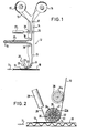
- Fig. 1 zeigt schematisch und allgemein eine Vorrichtung zum Aufbringen eines Aufreißbandes nach der Erfindung.
- Fig. 2 zeigt eine erste Ausführungsform zum Aufbringen des Aufreißbandes.
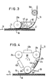
- Fig. 3 zeigt schematisch eine zweite Ausführungsform zum Aufbringen des Aufreißbandes.
- Fig. 4 zeigt schematisch eine dritte Ausführungsform zum Aufbringen des Aufreißbandes.
- Bevor auf die in den Zeichnungen dargestellten Einzelheiten näher eingegangen wird, sei vorangestellt, daß jedes der beschriebenen Merkmale für sich oder in Verbindung mit Merkmalen der Ansprüche von erfindungswesentlicher Bedeutung ist.
- Eine Wellpappenbahn 10 wird in Richtung des Pfeils 11 vorbewegt. Oberhalb der Wellpappenbahn 10 befindet sich die allgemein mit 12 bezeichnete Vorrichtung zum Aufbringen eines Aufreißstreifens 13. Die Vorrichtung 12 befindet sich entweder vor oder hinter einer Schneid- und Rillmaschine für die Wellpappenbahn 10. Die Vorrichtung 12 besitzt eine Halterung 14, die, was nicht gezeigt ist, quer zur Laufrichtung 11 der Wellpappenbahn 10 verschiebbar ist und mit Hilfe eines Pneumatikantriebes oder dergleichen verstellt werden kann. Dies geschieht zum einen, um ein Nachfahren der Bahnkante zu ermöglichen. Ferner muß die Position der Vorrichtung 12 bei einem Formatwechsel geändert werden, damit der Aufreißstreifen 13 an einer anderen Stelle (in Querrichtung gesehen) aufgebracht werden kann. Die Halterung 14 lagert zwei Vorratsrollen 15, 16.In der in Fig. 1 gezeigten Anordnung wird das Band 13 von der Vorratsrolle 16 abgezogen und über die Rollen 17, 18, 19 und 20 umgelenkt. Die Rollen 18 bis 20 sind so angeordnet, daß eine Schleife gebildet ist.
- Die Umlenkrolle 19 ist mittels einer Feder 21 vorgespannt. Die Schleife bzw. die Feder 21 dienen als Puffer, um Spannungei im Aufreißband 13 auszugleichen. An einem Arm 22 der Halterung 14 ist eine Anpreßrolle 23 drehbar gelagert. Sie dient dazu, das Band 13 gegen die Wellpappenbahn 10 anzudrücken. Zu diesem Zweck kann der Arm 22 mittels einer Feder gegen die Wellpappenbahn 10 vorgespannt werden. Am Anlenkpunkt des Arms 22 ist eine Führungsrolle 24 gelagert. Alle erwähnten Rollen sind freidrehend, da das Abziehen des Aufreißbandes 13 von der Rolle 16 über die Wellpappenbahn 10 erfolgt. Oberhalb der Umlenkrolle 18 sind zwei Spleißrollen 25, 26 angeordnet, wobei letzterer mit Hilfe eines Verstellzylinders 27 verstellbar ist. Im Spleißfalle wird die Rolle 26 mit Hilfe des Verstellzylinders 27 gegen die andere Rolle 25 angedrückt. Dadurch erfolgt eine Verbindung der beiden Bänder in diesem Bereich. Das erwähnte Spleißen ist besonders einfach, weil das Aufreißband 13 einseitig selbstklebend ist.
- Unmittelbar hinter der Anpreßrolle 23 - in Laufrichtung gesehen - ist ein Trennmesser 28 angeordnet, daß von einem Verstellzylinder 29 betätigbar ist, um das Aufreißband 23 zu durchtrennen.
- Bei der Ausführungsform nach Fig. 2 sind diejenigen Teile, die mit denen nach Fig. 1 übereinstimmen, mit gleichen Bezugszeichen versehen. Es ist zu erkennen, daß die Anpreßrolle 23b auf einer Nabe 30 dreht, die fest auf der Welle oder Achse 31 sitzt. Letztere besitzt eine radiale Bohrung 32, die ständig in Verbindung ist mit einem segmentartigen Kanal 33 in der Nabe 30. Die Rolle 23a besitzt eine Vielzahl von radialen Bohrungen 34, die an der Umfangsfläche münden. Die radiale Bohrung 31 in der Achse steht mit einer axialen Bohrung 35 in Verbindung, die an eine nicht gezeigte Vakuumquelle anschließbar ist.
- Im Normalfall ist die Bohrung 35 entlüftet. Die Führungsrolle 24a weist eine Umfangsnut 36 auf, in der das Band 13 geführt ist.
- Im Fall eines Formatwechsels wird das Messer 28 betätigt, damit das Band 13 auf der Wellpappenbahn 10 durchtrennt wird. Der kleine Einstich des Messers 28 in der Wellpappenbahn kann ohne weiteres hingenommen werden. Gleichzeitig oder kurz vorher ist die Bohrung 35 an Vakuum angeschlossen worden. Dadurch wird der Bereich des Umfangs der Anpreßrolle 23a, der dem Kanalsegment 33 gegenüberliegt, unter Unterdruck gesetzt. Das Band 13 wird dadurch festgehalten. Es ist darüber hinaus möglich, die Anpreßrolle 23a etwas anzuheben, um zu vermeiden, daß der Rest des Bandes 13 von der Wellpappenbahn 10 mitgenommen wird und das Band 13 nach wie vor von der Vorratsrolle abzieht.
- Bei der Ausführungsform nach Fig. 3 ist zwischen Führungsrolle 24a und Anpreßrolle 23b ein Vakuumkasten 40 angeordnet, dessen untere nach hinten schräg nach oben gebogene Führungsfläche 41 mit einer Reihe von Öffnungen versehen ist. Die Führungsfläche 41 ist in ausreichendem Abstand zur Wellpappenbahn 10 angeordnet, damit eine Berührung des Bandes 13 mit der Wellpappenbahn 10 erst im Bereich der Anpreßrolle 23b erfolgt. Andererseits ist die Fläche 41 jedoch so nah wie möglich an die Wellpappenbahn herangeführt. Innerhalb des Kastens 40 befindet sich eine Walze 42 mit einem Messer 43, die mit Hilfe eines nicht gezeigten motorischen Antriebs antreibbar ist, um das Band 13 durchzuschneiden. Im Falle eines Formatwechsels schneidet die Messerwalze 42 das Band 13 durch. Gleichzeitig wird der Vakuumkasten 40 an die Vakuumquelle angeschlossen. Dadurch wird Luft in Richtung der Pfeile 44 in den Kasten 40 hineingesaugt. Der Unterdruck hält das Band 13 gegen die Fläche 41. Anschließend kann die Vorrichtung in eine neue Position, wie bereits beschrieben, verfahren werden. Zum erneuten Wiederanfahren wird das Vakuum im Kasten 40 unterbrochen. Es kann auch ein leichter Druckstoß eingeleitet werden, um das Band 13 gegen die Oberfläche der Wellpappenbahn 10 anzudrücken. Alternativ kann der Kasten 40 etwas in Richtung der Wellpappenbahn 10 verstellbar sein, um das erste Aufkleben zu bewerkstelligen.
- Bei der Ausführungsform nach Fig. 4 sind drei Anpreßrollen 23c an einem sternförmigen Halter 46 drehbar gelagert. Die Anbringung der Anpreßrollen 23c ist derart, daß alle in der unteren Position als Anpreßrolle eingesetzt werden können. Der Halter 26 kann von einem geeigneten Stellantrieb verstellt werden. Zwischen den Anpreßrollen 23c sind Vakuumkästen 40c am Halter 46 befestigt. Sie weisen eine Führungsfläche 41c auf. Die Führungsfläche 41c eines Vakuumkastens 40c führt das Band 13 zur Anpreßrolle 23c, wie in der Zeichnung dargestellt. Im normalen Betrieb sind die Vakuumkästen 40c entlüftet. Im Falle eines Formatwechsels steuert das Messer 28 das Aufreißband 23 zwischen Anpreßrolle 23c und Vakuumkasten 40c hindurch. Gleichzeitig wird der entsprechende Vakuumkasten 40c an die Vakuumquelle angeschlossen, wie durch die Pfeile 44c angedeutet. Die Führungsfläche 41c ist damit mit Unterdruck beaufschlagt und hält das Band 13 fest. Bei einem erneuten Anfahren wird der sternförmige Halter 46 um 120° gedreht, so daß die nächste Anpreßrolle 23c die Funktion des Andrückens übernimmt. Während dieser Zeit bleibt der Vakuumkasten 40c an der Vakuumquelle angeschlossen, bis die neue Anpreßrolle 23c ihre Position erreicht hat. Anschließend wird der Vakuumkasten 40c entlüftet.
Claims (13)
- l. Vorrichtung zum Aufbringen eines Aufreißbandes oder dergleichen auf eine Wellpappen-, Pappen-, Papierbahn o. dgl. mit einem Gestell, in dem eine Anpreßrolle drehbar und quer zur Laufrichtung der Bahn verschiebbar gelagert ist, der das Band von einer Vorratsrolle zugeführt wird und die das Band gegen die Bahn andrückt, und einer Schneidvorrichtung zum Durchtrennen des Bandes bei einem Formatwechsel oder dergleichen, dadurch gekennzeichnet, daß die Schneidvorrichtung (28, 29, 42, 43) nahe der Anpreßrolle (23, 23a, 23b, 23c) angeordnet ist, der Anpreßrolle eine Festhaltevorrichtung zugeordnet ist, die das Aufreißband (13) wahlweise festhält oder freigibt und eine Steuervorrichtung die Schneidvorrichtung und die Festhaltevorrichtung steuert derart, daß im Fall des Formatwechsels annähernd gleichzeitig die Schneidvorrichtung das Band (13) durchtrennt und die Festhaltevorrichtung das Band erfaßt.
- 2. Vorrichtung nach Anspruch 1, dadurch gekennzeichnet, daß die Schneidvorrichtung (28, 29, 42, 43) in Laufrichtung des Bandes (13) gesehen hinter oder im Bereich der Festhaltevorrichtung angeordnet ist.
- 3. Vorrichtung nach Anspruch 1 oder 2, dadurch gekennzeichnet, daß die Festhaltevorrichtung eine untere an eine Vakuumquelle anschließbare Fläche (41) aufweist, an der das Band (13) entlanggeführt ist.
- 4. Vorrichtung nach Anspruch 3, dadurch gekennzeichnet, daß die Anpreßrolle (23a) an ihrem Umfang Vakuumöffnungen aufweist, die über radiale Bohrungen(34)mit einem an die Vakuumquelle angeschlossenen Vakuumkanal (35) in der Welle für die Anpreßrolle (23a) in Verbindung bringbar sind.
- 5. Vorrichtung nach Anspruch 4, dadurch gekennzeichnet, daß die Schneidvorrichtung (28, 29) hinter der Anpreßrolle (23) angeordnet ist und nur diejenigen radialen Bohrungen (34) jeweils an den Vakuumkanal (35) angeschlossen sind, die dem Anfang des Umschlingungsbereichs der Anpreßrolle (23a) zugekehrt sind.
- 6. Vorrichtung nach Anspruch 4 oder 5, dadurch gekennzeichnet, daß die Anpreßrolle (23, 23a) über eine Hubvorrichtung heb- und senkbar ist.
- 7. Vorrichtung nach Anspruch 3, dadurch gekennzeichnet, daß vor der Anpreßrolle (23b) ein an die Vakuumquelle anschließbarer Vakuumkasten (40) angeordnet ist, dessen untere als Führungsfläche (41) für das Band (13) dienende Seite mit Öffnungen versehen ist.
- 8. Vorrichtung nach Anspruch 7, dadurch gekennzeichent, daß die Schneidvorrichtung, vorzugsweise in Form einer Schneidrolle (42, 43) in dem Vakuumkasten (40) angeordnet ist.
- 9. Vorrichtung nach einem der Ansprüche 4 bis 8, dadurch gekennzeichnet, daß die an die Vakuumquelle anschließbare Fläche (41, 41c) wahlweise mit einer Druckluftquelle verbindbar ist.
- 10. Vorrichtung nach Anspruch 8, dadurch gekennzeichnet, daß der Vakuumkasten (40) mit seiner Hubvorrichtung heb- und senkbar ist.
- 11. Vorrichtung nach Anspruch 1 oder 2, dadurch gekennzeichnet, daß mindestens zwei Anpreßrollen (23c) an einem Arm eines Hebels (46) drehbar gelagert sind, der seinerseits um eine Drehachse drehbar gelagert ist, und zwischen den Anpreßrollen (23c) am Hebel die Festhaltevorrichtung (40c) angebracht ist.
- 12. Vorrichtung nach Anspruch 11, dadurch gekennzeichnet, daß die Festhaltevorrichtung relativ zueinander verstellbare Greifbacken aufweist, zwischen denen in geöffneter Stellung das Band ungehindert hindurchgeführt wird.
- 13. Vorrichtung nach den Ansprüchen 3 und 11, dadurch gekennzeichnet, daß die an die Vakuumquelle anschließbare Fläche (41c) am Hebelarm (46) angeordnet ist.
Priority Applications (1)
| Application Number | Priority Date | Filing Date | Title |
|---|---|---|---|
| EP85102379A EP0193626A1 (de) | 1985-03-02 | 1985-03-02 | Vorrichtung zum Aufbringen eines Aufreissbandes oder dergleichen auf Wellpappen-, Pappen-, Papierbahnen o. dgl. |
Applications Claiming Priority (1)
| Application Number | Priority Date | Filing Date | Title |
|---|---|---|---|
| EP85102379A EP0193626A1 (de) | 1985-03-02 | 1985-03-02 | Vorrichtung zum Aufbringen eines Aufreissbandes oder dergleichen auf Wellpappen-, Pappen-, Papierbahnen o. dgl. |
Publications (1)
| Publication Number | Publication Date |
|---|---|
| EP0193626A1 true EP0193626A1 (de) | 1986-09-10 |
Family
ID=8193339
Family Applications (1)
| Application Number | Title | Priority Date | Filing Date |
|---|---|---|---|
| EP85102379A Withdrawn EP0193626A1 (de) | 1985-03-02 | 1985-03-02 | Vorrichtung zum Aufbringen eines Aufreissbandes oder dergleichen auf Wellpappen-, Pappen-, Papierbahnen o. dgl. |
Country Status (1)
| Country | Link |
|---|---|
| EP (1) | EP0193626A1 (de) |
Cited By (6)
| Publication number | Priority date | Publication date | Assignee | Title |
|---|---|---|---|---|
| FR2633599A1 (fr) * | 1988-07-04 | 1990-01-05 | Stephanois Rech Mec | Dispositif pour faciliter la prehension de la partie d'un ruban adhesif devant etre saisie |
| DE3938410A1 (de) * | 1989-11-18 | 1991-05-23 | Focke & Co | Vorrichtung zum anbringen eines klebestreifens an einem faltkarton oder dergleichen |
| WO2000015531A1 (en) * | 1998-09-15 | 2000-03-23 | Minnesota Mining And Manufacturing Company | Apparatus for applying and cutting tape |
| WO2002008102A3 (de) * | 2000-07-20 | 2002-11-28 | Daimler Chrysler Ag | Abklebewerkzeug und verfahren zum automatisierten, serienmässigen applizieren von klebeband |
| DE10215648A1 (de) * | 2002-04-09 | 2003-11-06 | Schmermund Verpackungstechnik | Verfahren und Vorrichtung zum Aufbringen eines Aufreißfadens auf eine Verpackungsmaterialbahn |
| CN110370642A (zh) * | 2019-08-14 | 2019-10-25 | 周小鹏 | 一种用于增材打印的双压交换转式双通上料架 |
Citations (5)
| Publication number | Priority date | Publication date | Assignee | Title |
|---|---|---|---|---|
| US3970507A (en) * | 1974-10-17 | 1976-07-20 | Trw Inc. | Tape dispenser and method of dispensing tape |
| US4029537A (en) * | 1975-12-08 | 1977-06-14 | Pitney-Bowes, Inc. | Label applicator |
| FR2453095A1 (fr) * | 1979-04-03 | 1980-10-31 | Carle & Montanari Spa | Dispositif pour la jonction bout a bout de deux bandes de papier, ou analogues, en particulier dans des machines d'emballage |
| US4285752A (en) * | 1980-03-13 | 1981-08-25 | Camsco, Inc. | Automatic tape lay-up system |
| DE3226290A1 (de) * | 1982-07-14 | 1984-01-26 | Messerschmitt-Bölkow-Blohm GmbH, 8000 München | Verfahren und vorrichtung zum gesteuerten ablegen von fasern auf eine form |
-
1985
- 1985-03-02 EP EP85102379A patent/EP0193626A1/de not_active Withdrawn
Patent Citations (5)
| Publication number | Priority date | Publication date | Assignee | Title |
|---|---|---|---|---|
| US3970507A (en) * | 1974-10-17 | 1976-07-20 | Trw Inc. | Tape dispenser and method of dispensing tape |
| US4029537A (en) * | 1975-12-08 | 1977-06-14 | Pitney-Bowes, Inc. | Label applicator |
| FR2453095A1 (fr) * | 1979-04-03 | 1980-10-31 | Carle & Montanari Spa | Dispositif pour la jonction bout a bout de deux bandes de papier, ou analogues, en particulier dans des machines d'emballage |
| US4285752A (en) * | 1980-03-13 | 1981-08-25 | Camsco, Inc. | Automatic tape lay-up system |
| DE3226290A1 (de) * | 1982-07-14 | 1984-01-26 | Messerschmitt-Bölkow-Blohm GmbH, 8000 München | Verfahren und vorrichtung zum gesteuerten ablegen von fasern auf eine form |
Cited By (9)
| Publication number | Priority date | Publication date | Assignee | Title |
|---|---|---|---|---|
| FR2633599A1 (fr) * | 1988-07-04 | 1990-01-05 | Stephanois Rech Mec | Dispositif pour faciliter la prehension de la partie d'un ruban adhesif devant etre saisie |
| DE3938410A1 (de) * | 1989-11-18 | 1991-05-23 | Focke & Co | Vorrichtung zum anbringen eines klebestreifens an einem faltkarton oder dergleichen |
| US5121586A (en) * | 1989-11-18 | 1992-06-16 | Focke & Co., (Gmbh & Co) | Apparatus for attaching an adhesive tape to a folding carton or the like |
| WO2000015531A1 (en) * | 1998-09-15 | 2000-03-23 | Minnesota Mining And Manufacturing Company | Apparatus for applying and cutting tape |
| WO2002008102A3 (de) * | 2000-07-20 | 2002-11-28 | Daimler Chrysler Ag | Abklebewerkzeug und verfahren zum automatisierten, serienmässigen applizieren von klebeband |
| US7001478B2 (en) | 2000-07-20 | 2006-02-21 | Daimlerchrysler Ag | Adhesive application too and method for the automated and serial application of adhesive tape |
| DE10215648A1 (de) * | 2002-04-09 | 2003-11-06 | Schmermund Verpackungstechnik | Verfahren und Vorrichtung zum Aufbringen eines Aufreißfadens auf eine Verpackungsmaterialbahn |
| CN110370642A (zh) * | 2019-08-14 | 2019-10-25 | 周小鹏 | 一种用于增材打印的双压交换转式双通上料架 |
| CN110370642B (zh) * | 2019-08-14 | 2021-08-27 | 杭州聚纳电子科技有限公司 | 一种用于增材打印的双压交换转式双通上料架 |
Similar Documents
| Publication | Publication Date | Title |
|---|---|---|
| DE3816774C2 (de) | Verfahren und Vorrichtung zum Aufrollen einer Bahn | |
| DE3751754T2 (de) | Vorrichtung zum Befestigen einer Ersatzbahn an einer Bahn, die eine programmierte Bewegung durchführt, ohne eine solche Bewegung zu unterbrechen | |
| DE3786905T2 (de) | Vorrichtung zum Befestigen einer Ersatzbahn an eine sich bewegende Bahn. | |
| DE3521907C2 (de) | Vorrichtung zum Miteinanderverbinden eines Endes einer ersten Bahn und eines Anfangs einer zweiten Bahn | |
| DE3811138C2 (de) | ||
| DE3410181C2 (de) | Nähmaschine | |
| EP0060450B1 (de) | Vorrichtung zum Verbinden des hinteren Endes einer von einer auslaufenden Rolle abgezogenen Bahn mit dem vorderen Ende einer von einer Ersatzrolle abgezogenen Bahn | |
| DE2430514B2 (de) | Vorrichtung zum Verbinden einer von einer Ersatzwickelrolle abgezogenen Materialbahn mit einer von einer Vorratswickelrolle ablaufenden Materialbahn | |
| DE2721883A1 (de) | Verfahren zur uebertragung einer papierbahn in einer papiermaschine sowie vorrichtung zur ausfuehrung des verfahrens | |
| EP0458112A1 (de) | Vorrichtung zum Verbinden von Materialbahnen | |
| DE1906939A1 (de) | Verfahren und Vorrichtung zum Herstellen einer Stossverbindung zwischen den Enden zweier Kartonbahnen | |
| DE3042383A1 (de) | Glaettvorrichtung | |
| DE4107254A1 (de) | Verfahren und vorrichtung zum verbinden der enden von materialbahnen aus verpackungsmaterial | |
| DE2223557C2 (de) | Verfahren zum Aufbringen von Aufklebern auf eine Endlosbahn | |
| DE102006037189A1 (de) | Verfahren zum Durchführen eines Rollenwechsels bei einer Versorgungseinheit zum Zuführen eines bahnartigen Flachmaterials an eine Verpackungsmaschine oder dergleichen Verarbeitungsmaschine sowie Versorgungseinheit zum Durchführen dieses Verfahrens | |
| DE19809516B4 (de) | Vorrichtung und Verfahren zum automatischen Wechseln von Folienrollen | |
| EP0193626A1 (de) | Vorrichtung zum Aufbringen eines Aufreissbandes oder dergleichen auf Wellpappen-, Pappen-, Papierbahnen o. dgl. | |
| EP0071229B1 (de) | Verfahren zur kontinuierlichen Herstellung von Faltschachteln sowie Vorrichtung hierzu | |
| DE19607495A1 (de) | Verfahren und Vorrichtung zum automatischen Wechsel von Folienrollen, insbesondere bei der Herstellung von Faltschachteln mit Folienfenstern | |
| EP1318092B1 (de) | Verfahren und Vorrichtung zum Verbinden von Materialbahnen | |
| CH661281A5 (de) | Rolle eines klebebandes mit beidseitig klebenden klebematerialstuecken und vorrichtungen zur herstellung derselben. | |
| DE3834334C2 (de) | Bearbeitungseinrichtung zur Vorbereitung des Bahnendes einer Rolle einer Warenbahn | |
| DE3440107C2 (de) | ||
| DE4415316A1 (de) | Rollenwickelmaschine | |
| DE60115334T2 (de) | Vorrichtung zum Verbinden des ablaufenden Endes einer Papierrolle mit dem Anfang einer neuen Rolle |
Legal Events
| Date | Code | Title | Description |
|---|---|---|---|
| PUAI | Public reference made under article 153(3) epc to a published international application that has entered the european phase |
Free format text: ORIGINAL CODE: 0009012 |
|
| 17P | Request for examination filed |
Effective date: 19850320 |
|
| AK | Designated contracting states |
Kind code of ref document: A1 Designated state(s): AT BE CH DE FR GB IT LI NL |
|
| 17Q | First examination report despatched |
Effective date: 19861222 |
|
| STAA | Information on the status of an ep patent application or granted ep patent |
Free format text: STATUS: THE APPLICATION IS DEEMED TO BE WITHDRAWN |
|
| 18D | Application deemed to be withdrawn |
Effective date: 19870902 |
|
| RIN1 | Information on inventor provided before grant (corrected) |
Inventor name: NOR, JORGEN REHHOFF |