EP0512278B1 - Kugelauflage in einer Fördervorrichtung für Papierbogen - Google Patents
Kugelauflage in einer Fördervorrichtung für Papierbogen Download PDFInfo
- Publication number
- EP0512278B1 EP0512278B1 EP92106226A EP92106226A EP0512278B1 EP 0512278 B1 EP0512278 B1 EP 0512278B1 EP 92106226 A EP92106226 A EP 92106226A EP 92106226 A EP92106226 A EP 92106226A EP 0512278 B1 EP0512278 B1 EP 0512278B1
- Authority
- EP
- European Patent Office
- Prior art keywords
- ball
- balls
- bores
- passage
- sheet
- Prior art date
- Legal status (The legal status is an assumption and is not a legal conclusion. Google has not performed a legal analysis and makes no representation as to the accuracy of the status listed.)
- Expired - Lifetime
Links
- 230000035515 penetration Effects 0.000 claims description 6
- 238000004519 manufacturing process Methods 0.000 description 4
- 238000006073 displacement reaction Methods 0.000 description 2
- 238000007639 printing Methods 0.000 description 2
- 229920000742 Cotton Polymers 0.000 description 1
- 238000011161 development Methods 0.000 description 1
- 230000018109 developmental process Effects 0.000 description 1
- 230000002349 favourable effect Effects 0.000 description 1
- 238000007645 offset printing Methods 0.000 description 1
- 230000000149 penetrating effect Effects 0.000 description 1
- 230000000284 resting effect Effects 0.000 description 1
Images


Classifications
-
- B—PERFORMING OPERATIONS; TRANSPORTING
- B65—CONVEYING; PACKING; STORING; HANDLING THIN OR FILAMENTARY MATERIAL
- B65H—HANDLING THIN OR FILAMENTARY MATERIAL, e.g. SHEETS, WEBS, CABLES
- B65H5/00—Feeding articles separated from piles; Feeding articles to machines
- B65H5/06—Feeding articles separated from piles; Feeding articles to machines by rollers or balls, e.g. between rollers
- B65H5/062—Feeding articles separated from piles; Feeding articles to machines by rollers or balls, e.g. between rollers between rollers or balls
Definitions
- the invention relates to a ball support in a conveying device for paper sheets.
- the balls are each guided by a ball holder in their resting position.
- a ball cage is provided for each ball, which is inserted together with the ball into a holding opening provided for this purpose in the ball holder or pulled out of it.
- the use of such replacement cages requires undesirable additional manufacturing effort and additional work to replace the ball.
- irregularities in the correct position of the cages and thus the balls can easily occur, thereby putting the support function of the ball supports into question.
- ball supports in conveyors for paper sheets are known in which the balls can be removed or exchanged through openings in their ball guide bodies with the aid of special suction tools which are inserted through these openings.
- suction tools which are inserted through these openings.
- a paper conveying and paper guiding system is known from document US Pat. No. 3,951,402.
- pressure strips extending in the sheet conveying direction are arranged above the outer conveyor belts.
- This embodiment has the disadvantage that, in addition to the use of balls, additional internals in the form of spring-loaded thrust washers are necessary, and the balls can only be removed from the pressure strips with great difficulty using tools.
- ball guide bodies are arranged transversely to the main sheet conveying direction over the sheet conveying plane and are provided with a plurality of ball guide bores from which the balls can be removed or exchanged, the ball guide bores being provided with lateral engagement slots via which through, by engaging the balls from the outside, the latter can be removed or replaced through the ball guide holes.
- the balls can be safely pushed out of this through lateral opening from the outside through the opening provided for this purpose in the ball guide body. No special tools are required.
- a cotton swab or some other suitable thin engaging body can also be used, for example.
- the balls can be exchanged easily and quickly.
- Such a device is also inexpensive to manufacture.
- the spherical cap penetrating the slot can simply be taken along a body surface along the slot along the guide body can be removed through the opening.
- the body surface can simply be a hand or finger surface of the machine operator.
- the features of claim 4 enable a particularly simple to manufacture embodiment of ball supports in conveying devices, in particular in those conveying devices in which either the conveying means used is lowered during operation or the ball guide bodies are raised.
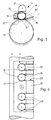
- FIGS. 1 and 2 show part of a sheet-fed offset rotary printing machine in which paper sheet 12 are conveyed via a feed table 1 to a printing unit 2 with impression cylinder 3, blanket cylinder 4 and plate cylinder 5.
- conveyor belts 8 are arranged on the feed table 1 around deflection rollers 9 and a conveyor roller 13 is arranged downstream of them in the conveying direction.
- the deflecting rollers 9, 10 and the conveyor rollers 13 are mounted in the side walls 6, 7 of the feed table 1.
- both above the conveyor belts 8 and above the conveyor rollers 13 are ball supports 11 to increase the frictional forces acting between the paper sheet 12 and the conveyor belts 8 or the conveyor roller 13 to the value required for the safe transportation of the paper sheets 12, which in turn depends on the respective operating requirements or 14 provided.
- the ball support 14 consists of a ball guide body 16 which is arranged transversely to the sheet conveying direction over the sheet feed table and which is fastened to the side parts 6, 7, for example, by means of retaining lugs 21 arranged in its two outer regions facing the side parts 6, 7.
- the ball guide body 16 is provided with ball guide bores 17 aligned perpendicular to the sheet conveying plane and arranged linearly next to one another transversely to the sheet conveying direction above the sheet feed table 1 and symmetrically to the center of the feed table.
- a retaining plate 19 is attached to the underside of the ball guide body 16. This is provided with circular penetration openings 20 arranged concentrically to the ball guide bores 17.
- the Penetration openings 20 have a diameter which is smaller than the diameter of the balls 15 used, but large enough that the balls 15 with a spherical cap extend sufficiently far through the respective penetration opening 20 to load the paper sheets 12 to be conveyed with their own weight.
- each ball guide bore 17 From the center of the bore of each ball guide bore 17, the ball guide body 16 and the retaining plate 19 are slit congruently outwards parallel to the ball guide bore 17 and the penetration opening 20 in the counter-arc conveying direction.
- the bore diameter of the ball guide bores 17 is dimensioned such that the balls 15 used are guided with play in them.
- a ball support designed in this way can also be used in sheet conveying devices in which cyclical sheet entrainment intervals due to cyclical changes in the distance between the ball guide body 16 and the conveying roller 13 are desired due to operational requirements.
- the conveyor roller 13 can be designed to be pivoted up and down in a cyclical manner with control means, not shown, such as a cam-controlled lever mechanism.
- the retaining plate 19 holds the balls 15 'back in the pivoted position of the conveyor roller 13.
- the conveyor roller 13 is pivoted up, the balls 15 'rest with their own weight on the conveyor rollers 13 or in sheet conveyance on the paper sheet 12 to be conveyed.
- the conveying roller 13 can, for example, also be equipped with a lateral displacement mechanism, not shown in detail in FIG. 2 with the aid of an arrow for the direction of displacement of the conveying roller 13, such as an axially cam-controlled lever mechanism, for the lateral entrainment of the paper sheet, for example for its lateral alignment .
- a lateral displacement mechanism not shown in detail in FIG. 2 with the aid of an arrow for the direction of displacement of the conveying roller 13, such as an axially cam-controlled lever mechanism, for the lateral entrainment of the paper sheet, for example for its lateral alignment .
- the operator can simply push the balls 15 upwards out of the ball guide bore 17 with the tip of a finger 22 which engages in the ball guide body 16 below the center of the ball 15 through the not quite finger-thick slot 18.
- lighter ball 15 for lighter, thinner paper sheets 12 to be conveyed can simply be dropped into the ball guide bore 17.
- the ball guide 11 can also be equipped in one of the described embodiments.
Landscapes
- Engineering & Computer Science (AREA)
- Mechanical Engineering (AREA)
- Delivering By Means Of Belts And Rollers (AREA)
- Supply, Installation And Extraction Of Printed Sheets Or Plates (AREA)
- Registering Or Overturning Sheets (AREA)
- Rollers For Roller Conveyors For Transfer (AREA)
- Feeding Of Articles By Means Other Than Belts Or Rollers (AREA)
Applications Claiming Priority (2)
| Application Number | Priority Date | Filing Date | Title |
|---|---|---|---|
| DE4114478A DE4114478C1 (enExample) | 1991-05-03 | 1991-05-03 | |
| DE4114478 | 1991-05-03 |
Publications (2)
| Publication Number | Publication Date |
|---|---|
| EP0512278A1 EP0512278A1 (de) | 1992-11-11 |
| EP0512278B1 true EP0512278B1 (de) | 1994-06-22 |
Family
ID=6430911
Family Applications (1)
| Application Number | Title | Priority Date | Filing Date |
|---|---|---|---|
| EP92106226A Expired - Lifetime EP0512278B1 (de) | 1991-05-03 | 1992-04-10 | Kugelauflage in einer Fördervorrichtung für Papierbogen |
Country Status (5)
| Country | Link |
|---|---|
| US (1) | US5277420A (enExample) |
| EP (1) | EP0512278B1 (enExample) |
| JP (1) | JPH0775882B2 (enExample) |
| AT (1) | ATE107603T1 (enExample) |
| DE (2) | DE4114478C1 (enExample) |
Families Citing this family (1)
| Publication number | Priority date | Publication date | Assignee | Title |
|---|---|---|---|---|
| DE9300919U1 (de) * | 1993-01-23 | 1993-03-25 | Mathias Bäuerle GmbH, 78112 St Georgen | Laufkontrollvorrichtung für bewegte Gegenstände |
Family Cites Families (12)
| Publication number | Priority date | Publication date | Assignee | Title |
|---|---|---|---|---|
| DE496215C (de) * | 1926-06-08 | 1930-04-16 | Georg Spiess | Seiten- und Ziehmarke fuer Bogenanleger an Druckmaschinen, Falzmaschinen o. dgl. |
| DE541477C (de) * | 1931-04-10 | 1932-01-13 | Kleim & Ungerer | Foerdervorrichtung fuer gefalzte und ungefalzte Bogen |
| GB449366A (en) * | 1935-07-02 | 1936-06-25 | Headley Townsend Backhouse | Improvements in or relating to machines for feeding sheets of paper, card or the like |
| DE830344C (de) * | 1950-06-30 | 1952-02-04 | Georg Spiess Dr Ing | Foerdertisch |
| DE964600C (de) * | 1955-01-05 | 1957-05-23 | Roland Offsetmaschf | Vorrichtung an bogenverarbeitenden Maschinen, wie Druckmaschinen, zum Abfuehlen der passerhaltigen Lage der Bogen |
| US3248106A (en) * | 1963-06-17 | 1966-04-26 | Camco Machinery Ltd | Sheet conveying mechanisms |
| US3630518A (en) * | 1969-06-16 | 1971-12-28 | Parnall & Sons Ltd | Sheet-feeding devices |
| US3663013A (en) * | 1970-06-15 | 1972-05-16 | Usm Corp | Work positioning devices |
| US3951402A (en) * | 1974-03-25 | 1976-04-20 | Skinner Lloyd D | Paper conveyor and guidance system |
| DE2758456A1 (de) * | 1977-12-28 | 1979-07-05 | Kurt Ruenzi | Sortiergeraet fuer papierblaetter |
| US4266762A (en) * | 1979-08-29 | 1981-05-12 | Xerox Corporation | Sheet alignment and feeding apparatus |
| DE3525040C2 (de) * | 1985-07-13 | 1994-05-11 | Bell & Howell Co | Einrichtung zur Umlenkung der Förderrichtung von Papierblättern |
-
1991
- 1991-05-03 DE DE4114478A patent/DE4114478C1/de not_active Expired - Lifetime
-
1992
- 1992-04-10 DE DE59200251T patent/DE59200251D1/de not_active Expired - Fee Related
- 1992-04-10 EP EP92106226A patent/EP0512278B1/de not_active Expired - Lifetime
- 1992-04-10 AT AT92106226T patent/ATE107603T1/de not_active IP Right Cessation
- 1992-04-24 JP JP4106487A patent/JPH0775882B2/ja not_active Expired - Lifetime
- 1992-05-04 US US07/877,861 patent/US5277420A/en not_active Expired - Fee Related
Also Published As
| Publication number | Publication date |
|---|---|
| JPH05193107A (ja) | 1993-08-03 |
| DE59200251D1 (de) | 1994-07-28 |
| DE4114478C1 (enExample) | 1992-07-09 |
| JPH0775882B2 (ja) | 1995-08-16 |
| ATE107603T1 (de) | 1994-07-15 |
| EP0512278A1 (de) | 1992-11-11 |
| US5277420A (en) | 1994-01-11 |
Similar Documents
| Publication | Publication Date | Title |
|---|---|---|
| EP0427015B1 (de) | Vorrichtung zum schwebenden Führen von zu fördernden Materialbahnen oder Materialablagebogen | |
| DE3134266A1 (de) | Vorrichtung zum aendern der bewegungsrichtung von briefen und aehnlichen rechteckigen sendungen | |
| EP1686084A1 (de) | Einrichtung zum Zusammentragen von Druckbogen an einer Förderstrecke einer umlaufenden Fördervorrichtung | |
| DE19740222A1 (de) | Vorrichtung zum Führen einer Endlospapierbahn | |
| DE3939212C2 (de) | Bogenleit- und -bremseinrichtung in Auslagen von Druckmaschinen | |
| DE2516847A1 (de) | Vorrichtung zum transportieren, zaehlen und/oder entwerten von eintrittskarten o.dgl. | |
| AT501863B1 (de) | Haltevorrichtung für tintenstrahldrucker | |
| DD159419A1 (de) | Tisch zum foerdern und seitlichen ausrichten von papierbogen | |
| DE68914686T2 (de) | Vorrichtung zum ablegen von kopieblättern. | |
| EP0512278B1 (de) | Kugelauflage in einer Fördervorrichtung für Papierbogen | |
| DE2655098C3 (de) | Belegzuführvorrichtung | |
| DE2548756A1 (de) | Foerdereinrichtung mit einer vorrichtung zum zurueckhalten von mehrfachsendungen | |
| EP1010525B1 (de) | Bogenführungseinrichtung für eine Druckmaschine | |
| DE2624170C3 (de) | Seitenausrichtvorrichtung | |
| DE4014780A1 (de) | Bogenleiteinrichtung | |
| DE3022650A1 (de) | Einrichtung zum ausrichten von bogen | |
| DE1101290B (de) | Hochkantfoerdereinrichtung fuer Briefe und aehnliche flache Sendungen | |
| DD135715B1 (de) | Wendevorrichtung fuer bogen an falzmaschinen u. dgl. | |
| EP0638498A1 (de) | Vorrichtung zur Betätigung seitlicher Bogenführungen an Rotationsdruckmaschinen | |
| EP0308688A2 (de) | Rundstapelbogenanleger | |
| DE69208593T2 (de) | Vorrichtung zum Vereinzeln und Zuführen von Papierblättern und Steuerungsverfahren dafür, und dieses Verfahren verwendender Kassenautomat | |
| EP2620400A1 (de) | Transportsystem zum Transport von Blechtafeln in eine Blechdruckmaschine oder Blechlackiermaschine | |
| DE3633459C2 (enExample) | ||
| EP0765746B1 (de) | Druckmaschine und Verfahren zum Bogentransport entlang mehrerer Formzylinder | |
| EP3812313B1 (de) | Plattentransportvorrichtung |
Legal Events
| Date | Code | Title | Description |
|---|---|---|---|
| PUAI | Public reference made under article 153(3) epc to a published international application that has entered the european phase |
Free format text: ORIGINAL CODE: 0009012 |
|
| 17P | Request for examination filed |
Effective date: 19920410 |
|
| AK | Designated contracting states |
Kind code of ref document: A1 Designated state(s): AT CH DE FR GB IT LI SE |
|
| GBC | Gb: translation of claims filed (gb section 78(7)/1977) | ||
| 17Q | First examination report despatched |
Effective date: 19930128 |
|
| GRAA | (expected) grant |
Free format text: ORIGINAL CODE: 0009210 |
|
| AK | Designated contracting states |
Kind code of ref document: B1 Designated state(s): AT CH DE FR GB LI |
|
| REF | Corresponds to: |
Ref document number: 107603 Country of ref document: AT Date of ref document: 19940715 Kind code of ref document: T |
|
| RBV | Designated contracting states (corrected) |
Designated state(s): DE FR GB |
|
| REF | Corresponds to: |
Ref document number: 59200251 Country of ref document: DE Date of ref document: 19940728 |
|
| ET | Fr: translation filed | ||
| GBT | Gb: translation of ep patent filed (gb section 77(6)(a)/1977) |
Effective date: 19940811 |
|
| PGFP | Annual fee paid to national office [announced via postgrant information from national office to epo] |
Ref country code: FR Payment date: 19950404 Year of fee payment: 4 |
|
| PLBE | No opposition filed within time limit |
Free format text: ORIGINAL CODE: 0009261 |
|
| STAA | Information on the status of an ep patent application or granted ep patent |
Free format text: STATUS: NO OPPOSITION FILED WITHIN TIME LIMIT |
|
| 26N | No opposition filed | ||
| PG25 | Lapsed in a contracting state [announced via postgrant information from national office to epo] |
Ref country code: GB Effective date: 19960410 |
|
| GBPC | Gb: european patent ceased through non-payment of renewal fee |
Effective date: 19960410 |
|
| PG25 | Lapsed in a contracting state [announced via postgrant information from national office to epo] |
Ref country code: FR Effective date: 19961227 |
|
| REG | Reference to a national code |
Ref country code: FR Ref legal event code: ST |
|
| PGFP | Annual fee paid to national office [announced via postgrant information from national office to epo] |
Ref country code: DE Payment date: 19990507 Year of fee payment: 8 |
|
| PG25 | Lapsed in a contracting state [announced via postgrant information from national office to epo] |
Ref country code: DE Free format text: LAPSE BECAUSE OF NON-PAYMENT OF DUE FEES Effective date: 20010201 |